

Page 1
Page 2

Page 3
• SAFETY PRECAUTIONS •
(Always read these instructions before using this equipment.)
Before using this product, please read this manual and the relevant manuals introduced in this manual
carefully and pay full attention to safety to handle the product correctly.
The instructions given in this manual are concerned with this product. For the safety instructions of the
programmable controller system, please read the CPU module User's Manual.
In this manual, the safety instructions are ranked as "DANGER" and "CAUTION".
DANGER
!
CAUTION
!
Note that the !CAUTION level may lead to a serious consequence according to the circumstances.
Always follow the instructions of both levels because they are important to personal safety.
Please save this manual to make it accessible when required and always forward it to the end user.
Indicates that incorrect handling may cause hazardous conditions,
resulting in death or severe injury.
Indicates that incorrect handling may cause hazardous conditions,
resulting in medium or slight personal injury or physical damage.
[Startup/Maintenance Instructions]
!
CAUTION
• Before performing the Original Position Return, JOG operation, positioning data or other test in
the test mode, read the manual carefully, fully ensure safety, and set the programmable
controller CPU to STOP.
Not doing so can damage the machine or cause an accident due to misoperation.
A - 1 A - 1
Page 4
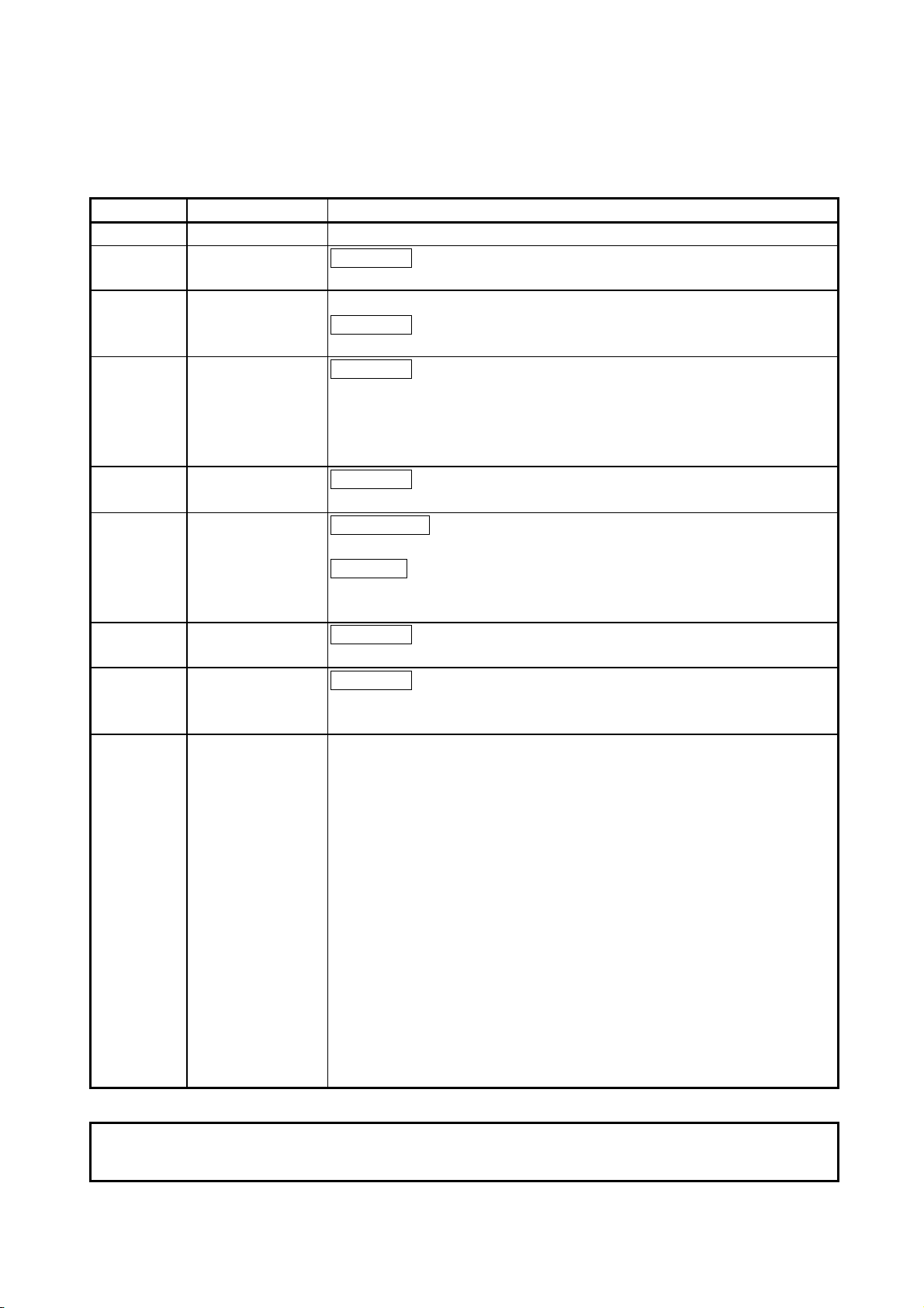
REVISIONS
* The manual number is given on the bottom left of the back cover.
Print Date * Manual Number Revision
Mar., 1999 IB (NA)-66900-A First edition
Jun., 2000 IB (NA)-66900-B
Correction
Packing List, Section 12.8.2
Jun., 2001 IB (NA)-66900-C The product name has been changed to GX Configurator-AP.
Correction
About the Generic Terms and Abbreviations, Packing List
Aug., 2001 IB (NA)-66900-D
Correction
CONTENTS, About the Generic Terms and Abbreviations, Packing List,
Chapter 1, Section 2.1, Section 2.2, Section 3.1, Chapter 4 to 6,
Section 7.2, Section 8.2, Section 12.4.5, Section 12.11, Appendix 1,
INDEX
Nov., 2001 IB (NA)-66900-E
Correction
Section 8.2.3, Appendix 2.3, Appendix 2.4
Feb., 2003 IB (NA)-66900-F
New addition
SOFTWARE USER REGISTRATION
Correction
INTRODUCTION, CONTENTS, Section 2.2, Section 4.1, Section 4.2,
Section 4.3, Appendix 2.3, Appendix 2.4, INDEX
Feb., 2004 IB (NA)-66900-G
Correction
SOFTWARE USER REGISTRATION, Section 2.1
Jan., 2008 IB(NA)- 66900-H
Correction
About the Generic Terms and Abbreviations, Section 2.2, Section 4.1,
Section 4.3, Appendix 2.4
This manual confers no industrial property rights or any rights of any other kind, nor does it confer any patent
licenses. Mitsubishi Electric Corporation cannot be held responsible for any problems involving industrial property
rights which may occur as a result of using the contents noted in this manual.
© 1999 MITSUBISHI ELECTRIC CORPORATION
Japanese Manual Version IB-80031-I
A - 2 A - 2
Page 5

—— SOFTWARE USER REGISTRATION ——
After agreeing to the terms of the Software License Agreement included in the package, please access the
MELFANSweb Home Page (http://www.MitsubishiElectric.co.jp/melfansweb) and make a software user
registration. (User registration is free of charge.)
You can also make a registration by faxing or mailing the "Software Registration Card" packed with the
product.
1. Software Registration
You can make a software registration by accessing the MELFANSweb Home Page or faxing or mailing the
"Software Registration Card" packed with the product.
After you have made a software registration, we will register the user and send the "Software registration
confirmation" together with the user ID.
We will also provide the latest information, such as the new product release, version upgrade information
and event information, by direct mail.
2. Notes on Contact
Please ask questions concretely and clearly using terms listed in the manual.
When requesting us to solve a problem, provide us with detailed information for reproducing the problem.
In addition, contact the respective manufacturers when asking questions about the operating system (OS) or
the other vender's software products
User registration is valid only in Japan.
A - 3 A - 3
Page 6

INTRODUCTION
Thank you for choosing the Mitsubishi MELSOFT Series Integrated FA software.
Read this manual and make sure understand the functions and performance of MELSOFT series thoroughly
in advance to ensure correct use.
CONTENTS
SAFETY PRECATIONS ................................................................................................................................A- 1
REVISIONS ....................................................................................................................................................A- 2
SOFTWARE USER REGISTRATION...........................................................................................................A- 3
INTRODUCTION............................................................................................................................................A- 4
CONTENTS....................................................................................................................................................A- 4
About Manuals ...............................................................................................................................................A- 8
How to Use This Manual................................................................................................................................A- 9
About the Generic Terms and Abbreviations ................................................................................................A-11
Packing List ....................................................................................................................................................A-11
1. OVERVIEW 1- 1 to 1- 8
1.1 Features ................................................................................................................................................... 1- 2
1.2 Manual Makeup........................................................................................................................................ 1- 7
2. SYSTEM CONFIGURATION 2- 1 to 2- 5
2.1 System Configuration............................................................................................................................... 2- 1
2.2 Operating Environment ............................................................................................................................ 2- 4
3. FUNCTION LIST 3- 1 to 3- 3
3.1 Function List .............................................................................................................................................3- 1
4. INSTALLATION AND UNINSTALLATION 4- 1 to 4-12
4.1 Installation ................................................................................................................................................ 4- 1
4.2 Uninstallation............................................................................................................................................ 4- 8
4.3 Starting GX Configurator-AP ...................................................................................................................4-10
4.4 Ending GX Configurator-AP..................................................................................................................... 4-11
5. SCREEN MAKEUP AND BASIC OPERATIONS 5- 1 to 5- 4
5.1 Screen Makeup ........................................................................................................................................ 5- 1
5.2 Basic Operations...................................................................................................................................... 5- 2
A - 4 A - 4
Page 7

6. PROJECT CREATION 6- 1 to 6-11
6.1 Creating a New Project ............................................................................................................................ 6- 2
6.2 Opening the Existing Project ................................................................................................................... 6- 4
6.3 Saving the Project .................................................................................................................................... 6- 5
6.4 Deleting the Project.................................................................................................................................. 6- 6
6.5 Reading the Other Format File (Import file) ............................................................................................6- 7
6.5.1 Reading the SW1∗-AD75P format file .............................................................................................. 6- 7
6.5.2 Reading the CSV format file .............................................................................................................6- 8
6.6 Write to Other Format File (Export file) ................................................................................................... 6-10
6.6.1 Saving in SW1∗-AD75P format file ................................................................................................... 6-10
6.6.2 Saving in CSV format file .................................................................................................................. 6-11
7. SYSTEM CHECKING FROM PERIPHERAL DEVICE 7- 1 to 7-16
7.1 Checking the AD75 Module Version (OS Information) ...........................................................................7- 2
7.2 AD75P Checking Connect ....................................................................................................................... 7- 3
7.3 AD75M Servo Starting Up ....................................................................................................................... 7- 6
7.3.1 Servo initial check ............................................................................................................................. 7- 7
7.3.2 Servo model name check ................................................................................................................. 7- 9
7.3.3 Servo upper/lower limit check........................................................................................................... 7-11
7.3.4 Servo speed check............................................................................................................................ 7-14
8. PARAMETER SETTING 8- 1 to 8-12
8.1 Parameters ............................................................................................................................................... 8- 1
8.1.1 Basic parameter 1 setting screen ..................................................................................................... 8- 3
8.1.2 Basic parameter 2 setting screen ..................................................................................................... 8- 4
8.1.3 Extended parameter 1 setting screen .............................................................................................. 8- 5
8.1.4 Extended parameter 2 setting screen .............................................................................................. 8- 6
8.1.5 OPR basic parameter setting screen ............................................................................................... 8- 7
8.1.6 OPR extended parameter setting screen ......................................................................................... 8- 8
8.2 Servo Parameters .................................................................................................................................... 8- 9
8.2.1 Servo basic parameter setting screen .............................................................................................. 8-10
8.2.2 Servo adjustment parameter setting screen .................................................................................... 8-11
8.2.3 Servo extension parameter setting screen....................................................................................... 8-12
9. SETTING OF POSITIONING DATA AND START BLOCK DATA 9- 1 to 9-14
9.1 Positioning Data Setting........................................................................................................................... 9- 1
9.2 Positioning Data Checking....................................................................................................................... 9- 4
9.2.1 Error check ........................................................................................................................................9- 4
9.2.2 Offline simulation ............................................................................................................................... 9- 6
9.3 Start Block Data Setting ........................................................................................................................... 9- 8
9.4 Condition Data Setting ............................................................................................................................. 9-10
9.5 Indirect Data Setting................................................................................................................................. 9-12
9.6 M Code Comment Setting ....................................................................................................................... 9-13
A - 5 A - 5
Page 8

10. POSITIONING MODULE DATA WRITE/READ/VERIFY 10- 1 to 10- 5
10.1 Write to AD75/Read from AD75/Verify AD75 Data............................................................................. 10- 1
10.2 Flash ROM write/read request to AD75 .............................................................................................. 10- 5
11. POSITIONING DEBUGGING 11- 1 to 11-48
11.1 Monitor.................................................................................................................................................. 11- 2
11.1.1 Monitoring the positioning data/start block data........................................................................... 11- 2
11.1.2 Operation monitor (main screen) .................................................................................................. 11- 4
11.1 3 History monitor ..............................................................................................................................11- 6
11.1.4 Signal monitor ............................................................................................................................... 11- 8
11.1.5 Operation monitor (dialog) ............................................................................................................ 11-11
11.1.6 Servo monitor ................................................................................................................................11-17
11.1.7 Sampling monitor ..........................................................................................................................11-21
11.2 Test ....................................................................................................................................................... 11-23
11.2.1 Positioning data-specified operation ............................................................................................ 11-23
11.2.2 Start block data-specified operation .............................................................................................11-28
11.2.3 Positioning start test (Current value change test) ........................................................................ 11-31
11.2.4 Speed change test ........................................................................................................................11-33
11.2.5 OPR test ........................................................................................................................................11-36
11.2.6 JOG operation test ........................................................................................................................ 11-38
11.2.7 MPG operation test .......................................................................................................................11-41
11.2.8 Torque control test ........................................................................................................................ 11-43
11.3 Position Control Gain Adjustment ....................................................................................................... 11-45
11.4 Servo Off .............................................................................................................................................. 11-48
12. USEFUL FUNCTIONS 12- 1 to 12-43
12.1 Useful Functions for Project Execution ............................................................................................... 12- 1
12.1.1 Verifying the project data ..............................................................................................................12- 1
12.1.2 Changing the AD75 model after data setting ............................................................................... 12- 3
12.1.3 Changing the view......................................................................................................................... 12- 4
12.2 Edit Functions for Data Setting............................................................................................................ 12- 5
12.2.1 Cut/copy/paste .............................................................................................................................. 12- 5
12.2.2 Jump .............................................................................................................................................. 12- 9
12.2.3 Clearing the rows/columns ........................................................................................................... 12-10
12.2.4 Initializing the data......................................................................................................................... 12-11
12.3 Copying the Data ................................................................................................................................. 12-12
12.3.1 Copying the data on an axis basis (Axis copy) ............................................................................12-12
12.3.2 Copying the data on a start block basis (Start block copy).......................................................... 12-13
12.4 Auxiliary Functions for Data Input........................................................................................................ 12-14
12.4.1 Parameter initializing wizard ......................................................................................................... 12-14
12.4.2 Servo parameter initializing wizard ............................................................................................... 12-16
12.4.3 Positioning data input auxiliary function ....................................................................................... 12-18
12.4.4 Start block data input auxiliary function ........................................................................................12-19
12.4.5 Registering the servo model names............................................................................................. 12-20
A - 6 A - 6
Page 9

12.5 GX Configurator-AP Option Function .................................................................................................. 12-23
12.6 Printing the Project Data ......................................................................................................................12-25
12.6.1 Printer setting ................................................................................................................................ 12-25
12.6.2 Printing........................................................................................................................................... 12-26
12.7 Teaching ............................................................................................................................................... 12-30
12.8 Wavy Display........................................................................................................................................ 12-32
12.8.1 Wavy display condition setting...................................................................................................... 12-32
12.8.2 Wavy display execution ................................................................................................................12-34
12.9 Tracks Display...................................................................................................................................... 12-36
12.9.1 Tracks display condition setting.................................................................................................... 12-36
12.9.2 Tracks display execution............................................................................................................... 12-38
12.10 Initializing the AD75 ...........................................................................................................................12-40
12.11 Help ....................................................................................................................................................12-41
APPENDICES Appendix- 1 to Appendix - 6
APPENDIX 1 SAMPLING MONITOR AND TRACE SCREEN PRINTING PROCEDURE...........Appendix - 1
APPENDIX 2 COMPARISON OF THE AD75 VERSIONS ............................................................Appendix - 3
Appendix 2.1 Comparison between AD75P1/2/3 and AD75P1-S3/2-S3/3-S3 ..........................Appendix - 3
Appendix 2.2 Comparison between Older and Newer Versions of A1SD75P1-S3/P2-S3/P3-S3 and
AD75P1-S3/P2-S3/P3-S3 .....................................................................................Appendix - 4
Appendix 2.3 Comparison between Older and Newer Versions of A1SD75M1/M2/M3 and
AD75M1/M2/M3 ....................................................................................................Appendix - 5
Appendix 2.4 Comparison of GX Configurator-AP Versions ......................................................Appendix - 5
APPENDIX 3 REFERENCE PROCESSING TIME FOR READ FROM/WRITE TO AD75...........Appendix - 6
INDEX Index - 1 to Index - 8
Index ....................................................................................................................................................... Index - 1
Menu-based Index ................................................................................................................................. Index - 6
A - 7 A - 7
Page 10
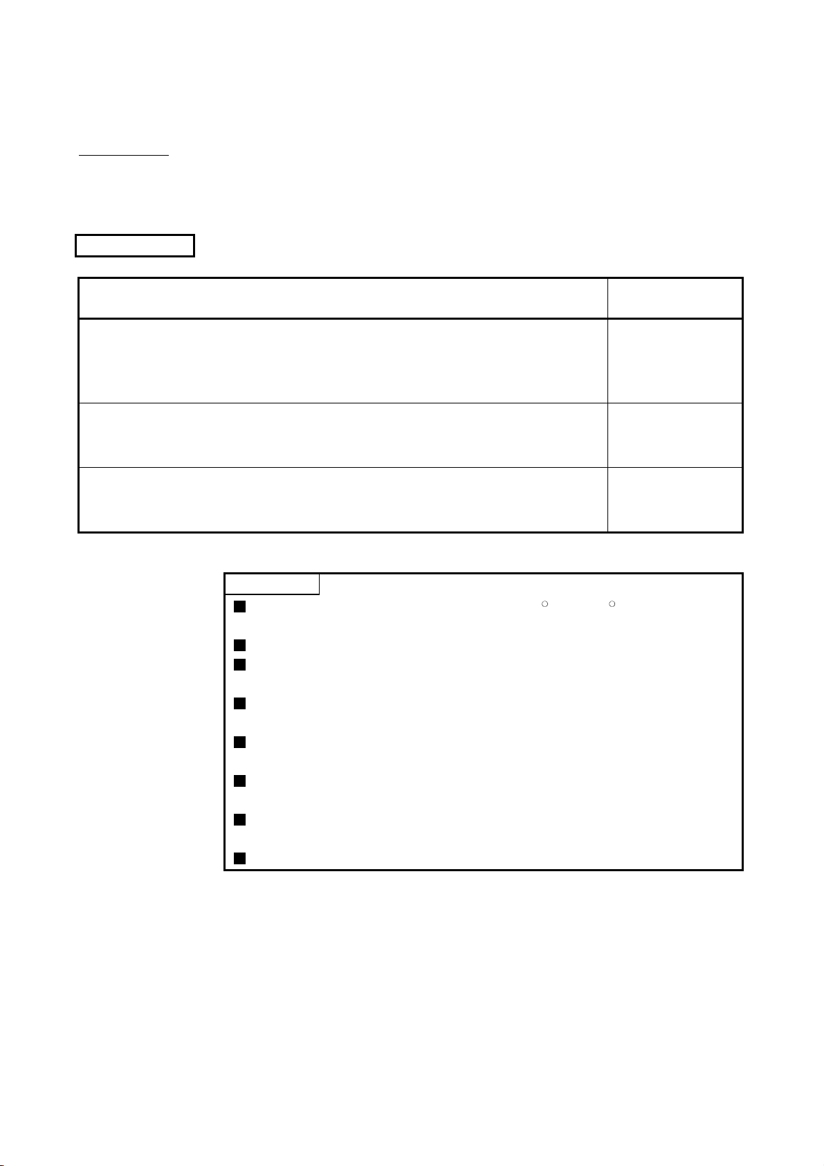
About Manuals
The following manuals are also related to this product.
In necessary, order them by quoting the details in the tables below.
Related Manuals
Manual Name
Positioning Module Type A1SD75P1-S3/P2-S3/P3-S3, AD75P1-S3/P2-S3/P3 User's Manual
Describes the system configuration, performance specifications, functions, handling, pre-operation
procedure and troubleshooting of Type A1SD75P1-S3/P2-S3/P3-S3 and AD75P1-S3/P2-S3/P3-S3.
(Sold separately)
Manual Number
(Model Code)
IB-66716
(13J871)
Positioning Module Type A1SD75M1/M2/M3, AD75M1/M2/M3 User's Manual
Describes the system configuration, performance specifications, functions, handling, pre-operation
procedure and troubleshooting of Type A1SD75M1/M2/M3 and AD75M1/M2/M3. (Sold separately)
AJ65BT-D75P2-S3 Positioning Module User's Manual
Describes the system configuration, performance specifications, functions, handling, pre-operation
procedure and troubleshooting of Type AJ65BT-D75P2-S3. (Sold separately)
CAUTION
Please note that we do not guarantee the MicrosoftR WindowsR Operating System
corresponding commercially available software products that we introduce.
The software copyright of this product belongs to Mitsubishi Electric Corporation.
No part of the contents of this manual may be reproduced or transmitted in any
form or by any means without the permission of our company.
Some part of the contents of this manual may not follow the revisions of the
software and hardware.
In principle, the software of this product should be purchased per computer as a
set or under license.
This product (including the manual) may only be used under the software using
agreement.
Please note that we are not responsible for any influence resulting from the
operation of this product (including the manual).
The contents of this manual are subject to change without notice.
IB-66715
(13J870)
IB-66824
(13JL46)
A - 8 A - 8
Page 11
How to Use This Manual
PURPOSE
Purpose of operation explained in each
chapter, section and paragraph.
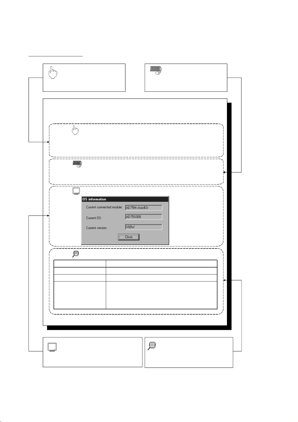
7.1 Checking the AD75 Module Version (OS Information)
PURPOSE
Depending on the software version of the AD75 module, the parameters and
some functions cannot be used.
Before setting various data, check the software version of the module on the
peripheral device.
BASIC OPERATION
1. Click the [Online] → [OS information] menu.
2. Check the software version in the OS information dialog box.
3. To exit, click the "Close" button.
DISPLAY/SETTING SCREEN
BASIC OPERATION
Operation to be performed until the actual
operation screen appears.
DISPLAY/SETTING DATA
Item
Current connected module
Current OS
Current version
Indicates the model of the AD75 connected.
Indicates the OS name of the AD75 connected.
Indicates the software version of the AD75 connected.
The parameters and some functions cannot be used
depending on the software version of the AD75.
Refer to Appendix 2 for differences between the
software versions of the AD75.
DISPLAY/SETTING SCREEN
Screen used to make setting or provide
display for the purpose.
Description
DISPLAY/SETTING DATA
Explains the display/setting screen items.
A - 9 A - 9
Page 12
N
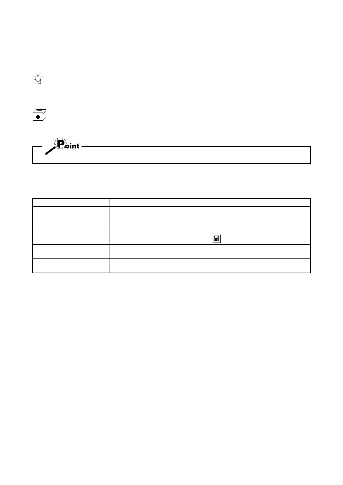
In addition, there are also the following explanations.
HELPFUL OPERATIO
Describes application operation if there are multiple purposes and the basic operation and display/setting
data do not provide enough information.
HELPFUL CORRECTIVE ACTIONS
Explains corrective actions if monitored data is abnormal or a test cannot be made.
Provides information relevant to that page, e.g. the items you should be careful of and the functions you
should know.
The following table lists the symbols used in this manual and their definitions.
Symbol Description
Represents the name of the menu bar.
[ ]
( )
" "
<< >>
→ [ ] indicates a drop-down menu.
Example: [Project] → [New Project] menu
Represents the tool button on the toolbar corresponding to the drop-down menu.
Example: [Project] → [Save Project] menu (
Represents the command button in the dialog box.
Example: "OK" button
Represents the tab in the dialog box.
Example: <<Basic Parameter 1>> tab
)
A - 10 A - 10
Page 13
About the Generic Terms and Abbreviations
The following abbreviations and generic names for type AD75 positioning module
software, type AD75 positioning modules, etc. are used in this manual.
Generic Term/Abbreviation Description
GX Configurator-AP
Generic product name for type SW0D5C-AD75P-E and SW0D5C-AD75P-EA means a
multiple license product.
SW1∗ -AD75P Abbreviation for type SW1IVD-AD75P positioning module software package
Generic name for type AD75P1, AD75P2, AD75P3, A1SD75P1, A1SD75P2, A1SD75P3,
AD75P
AD75P1-S3, AD75P2-S3, AD75P3-S3, A1SD75P1-S3, A1SD75P2-S3, A1SD75P3-S3
and AJ65BT-D75P2-S3 positioning modules
AD75M
Generic name for type AD75M1, AD75M2, AD75M3, A1SD75M1, A1SD75M2 and
A1SD75M3 positioning modules
AD75 Generic name for positioning modules that may be used with GX Configurator-AP.
Peripheral device Generic name for personal computers on which GX Configurator-AP may be used.
Generic name for the following relevant manuals
• Positioning Module Type A1SD75P1-S3/P2-S3/P3-S3, AD75P1-S3/P2-S3/P3 User's
AD75 User's Manual
Manual
• Positioning Module Type A1SD75M1/M2/M3, AD75M1/M2/M3 User's Manual
• AJ65BT-D75P2-S3 Positioning Module User's Manual
Servo amplifier Generic name for pulse input processing drive units that may be connected to the AD75
Servomotor Generic name for motors connected to the drive unit (servo amplifier)
Positioning system
Personal computer
Generic name for an equipment set which exercises positioning control, including the
positioning module, servo amplifiers, servomotors and external switches
Abbreviation for IBM PC/AT
R
or compatible DOS/V personal computer
1-license product Abbreviation for 1-license product of GX Configurator-AP
Maltiple-license product Abbreviation for multiple-license product of GX Configurator-AP
Generic term for the following:
Windows VistaR
MicrosoftRWindows VistaRHome Basic Operating System,
Microsoft
Microsoft
Microsoft
Microsoft
R
Windows VistaRHome Premium Operating System,
R
Windows VistaRBusiness Operating System,
R
Windows VistaRUltimate Operating System,
R
Windows VistaREnterprise Operating System
Generic term for the following:
WindowsRXP
MicrosoftRWindowsRXP Professional Operating System,
Microsoft
R
WindowsRXP Home Edition Operating System
Packing List
The GX Configurator-AP consists of the following products.
Type Product Name Quantity
SW0D5C-AD75P-E
SW0D5C-AD75P-EA
GX Configurator-AP Version 1 (1-license product) (CD-ROM)
End-user software license agreement 1
Software registration card 1
License agreement 1
GX Configurator-AP Version 1 (Multiple license product) (CD-ROM)
End-user software license agreement 1
Software registration card
n
License agreement 1
1
1
∗1
∗1 : The same number of software registration cards as that of licenses are packed with the product.
A - 11 A - 11
Page 14

MEMO
A - 12 A - 12
Page 15

1. OVERVIEW
MELSOFT
1. OVERVIEW
This manual describes the functions and operating procedures of
"GX Configurator-AP" (hereinafter referred to as GX Configurator-AP).
GX Configurator-AP is a positioning module software package which can perform the
following functions.
• Setting of positioning data and parameters
• Read/write of data from/to positioning module
• Monitoring of positioning control status
• Test operation of positioning control
• Initial operation test of servo amplifiers and motors
GX Configurator-AP can be used with any of the following positioning modules.
Positioning
Module Type
1 axis
2 axis
3 axis
Building block type
AD75P1,
AD75P1-S3,
AD75M1
AD75P2,
AD75P2-S3,
AD75M2
AD75P3,
AD75P3-S3,
AD75M3
Number of control axis
Compact building
block type
A1SD75P1,
A1SD75P1-S3,
A1SD75M1
A1SD75P2,
A1SD75P2-S3,
A1SD75M2
A1SD75P3,
A1SD75P3-S3,
A1SD75M3
CC-Link intelligent
device station
-
AJ65BT-D75P2-D3
-
1
1 - 1 1 - 1
Page 16
c
1. OVERVIEW
1.1 Features
MELSOFT
1
This section explains the features of GX Configurator-AP.
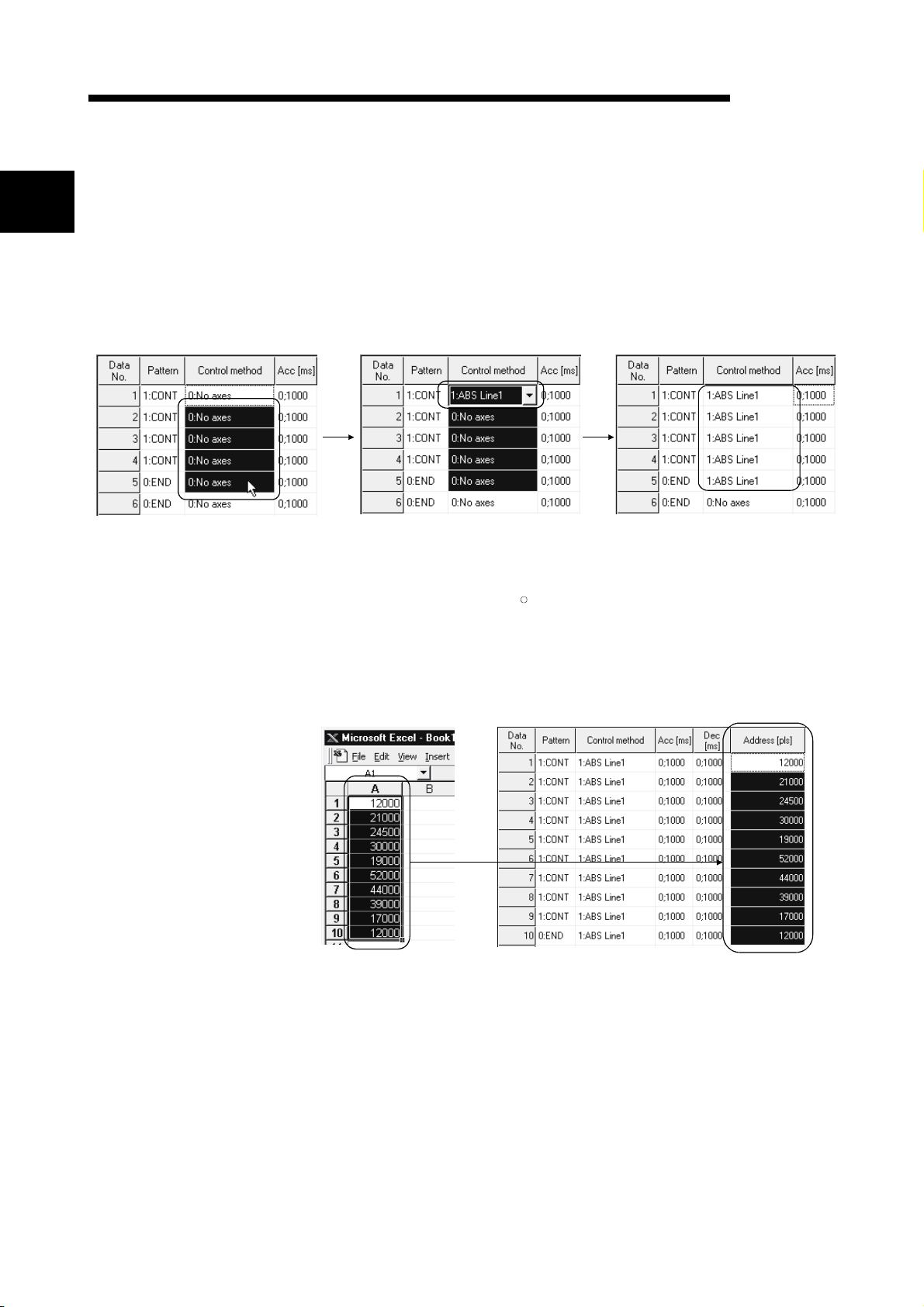
(1) Outstanding operability
1) Positioning data and start block data can be cut, copied and
pasted efficiently.
Drag the batch setting range! Typing "1" sets "1: ABS Line 1" in the top cell!
2) Data created with MicrosoftR Excel or Word can be copied and
[Useful drag range batch setting operation example]
utilized as positioning data.
[Example of utilizing Excel data as positioning data]
Excel worksheet
Positioning setting screen
Pressing the Enter key batch-sets "1:
ABS Line 1" in all cells in the dragged
range!
Copy the address data
reated with Excel !
Choose and paste the
utilized data No. column!
1 - 2 1 - 2
Page 17
1. OVERVIEW
MELSOFT
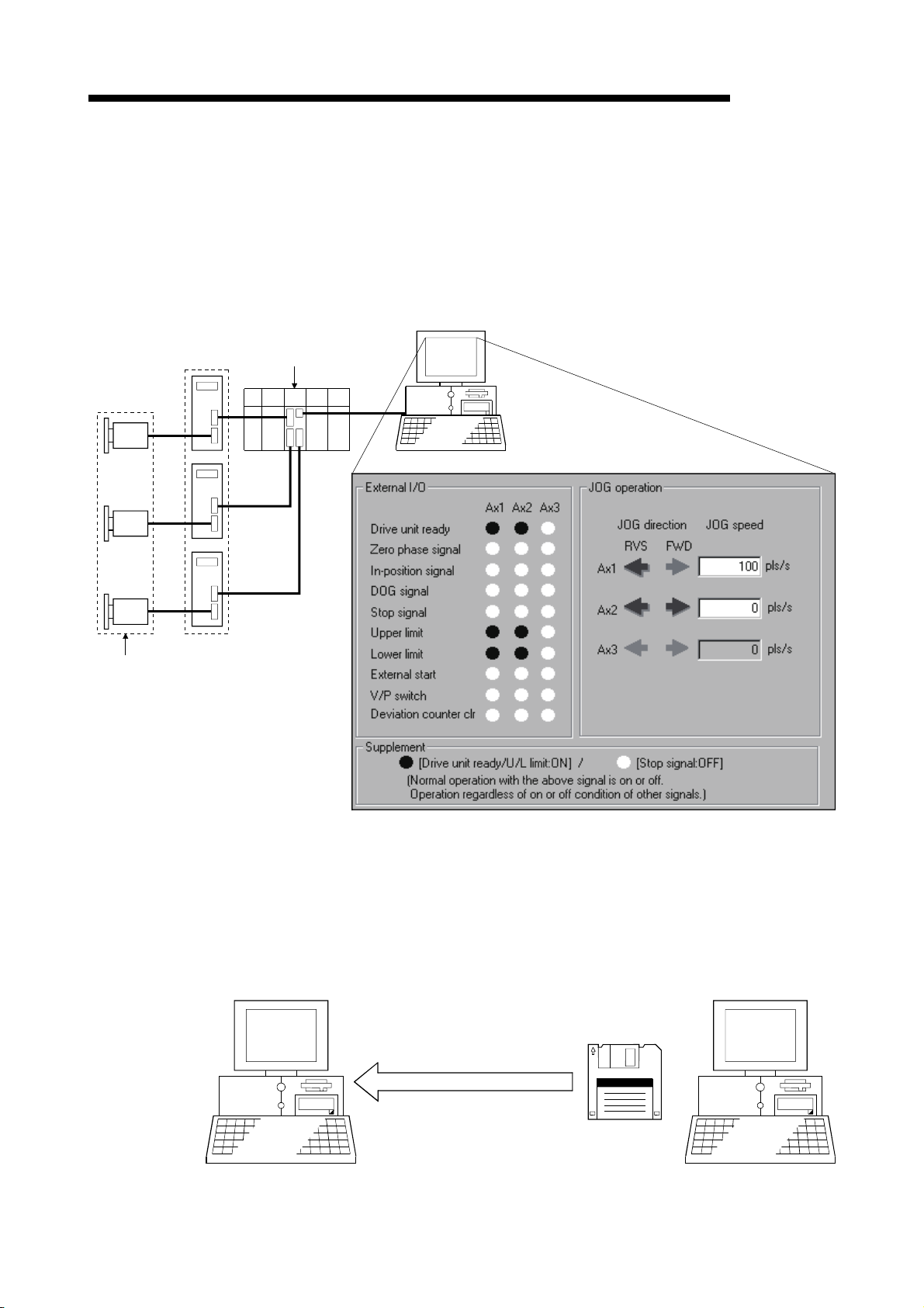
(3) Checking connect of general-purpose servo system
In a general-purpose servo system which uses the AD75P(S3) positioning
module, the checking connect function of GX Configurator-AP allows the
AD75P(S3) to be initialized, I/O signals to/from external devices to be monitored,
and JOG operation to be performed.
The connection of the positioning system can be checked by monitoring signals
from the external devices, and the rotation directions of servomotors can be
checked by performing JOG operation.
Servo amplifiers
External devices such as servomotors
and limit switches
(4) Utilization of SW1RX/IVD/NX-AD75P data
GX Configurator-AP
AD75P
Connection of the positioning system using
the AD75P can be checked from the
peripheral device.
Since the data created with type SW1RX/IVD/NX-AD75P positioning module
software package can be utilized on GX Configurator-AP, valuable resources can
be used efficiently.
GX Configurator-AP may also be saved as SW1RX/IVD/NX-AD75P format data.
[Data utilization example]
SW1IVD-AD75P
Open other format file.
Existing data created
with SW1IVD-AD75P
1 - 3 1 - 3
Page 18
1. OVERVIEW
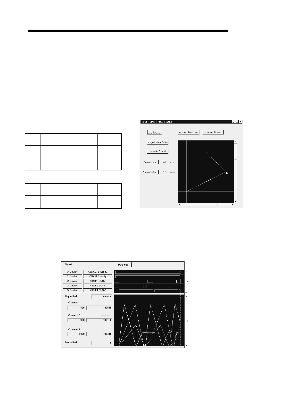
(5) Enhanced functions assist debugging and maintenance
Functions have been enhanced the offline simulation function displays a virtual
positioning result which has been calculated from the addresses and command
speeds set in positioning data and the monitor function is useful for debugging
and maintenance of the positioning system, e.g. sampling monitor which shows
the positioning module's I/O signal, external I/O signal and buffer memory states
with a line graph.
This example assumes that the following
positioning data was offline simulated.
Positioning data #1
Data
Pattern
No.
1 CONT
2 END
Control
Method
ABS
Line 2
ABS
Line 2
Positioning data #2
Data
Pattern
No.
1 - - 100 -
2 - - 200 -
Control
Method
Locus data is displayed for 2-axis interpolation control.
Waveform data of speed is displayed for 1-axis control.
When positioning data is set, offline simulation allows
you to pre-assume axis operation in advance, reducing
debugging time.
[Offline simulation example]
Address
200
100
Address
Command
Speed
150,000
pls/s
150,000
pls/s
Command
Speed
[Sampling monitor example]
MELSOFT
2-axis interpolation simulation screen
Out of AD75's I/O signals, external I/O
signals and status signals, up to 5 points
can be monitored.
In a line graph, up to 3 points can be
monitored from buffer memory.
1 - 4 1 - 4
Page 19
1. OVERVIEW
<Online help function>
MELSOFT
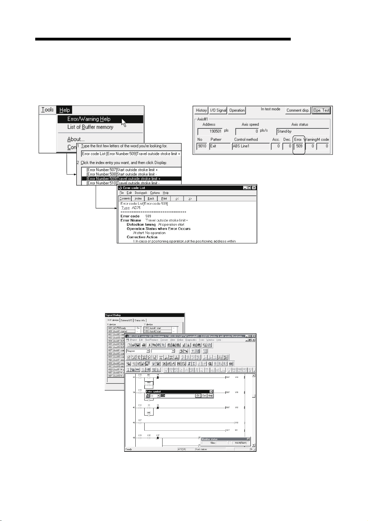
(6) Real-time checking of error and warning factors
With the online help function, you can instantaneously check the occurrence
factor and corrective action of the error or warning code displayed on the
operation monitor, error history monitor or other screen of the positioning system.
<Operation monitor>
Error occurrence!
(7) Simultaneous start of GX Configurator-AP and GX Developer
GX Configurator-AP can be started simultaneously with the GX Developer.
(Two COM ports are required to make communication with the programmable
controller CPU and positioning module at the same time.)
[Example of starting GX Configurator-AP and GX Developer simultaneously]
1 - 5 1 - 5
Page 20
1. OVERVIEW
MELSOFT
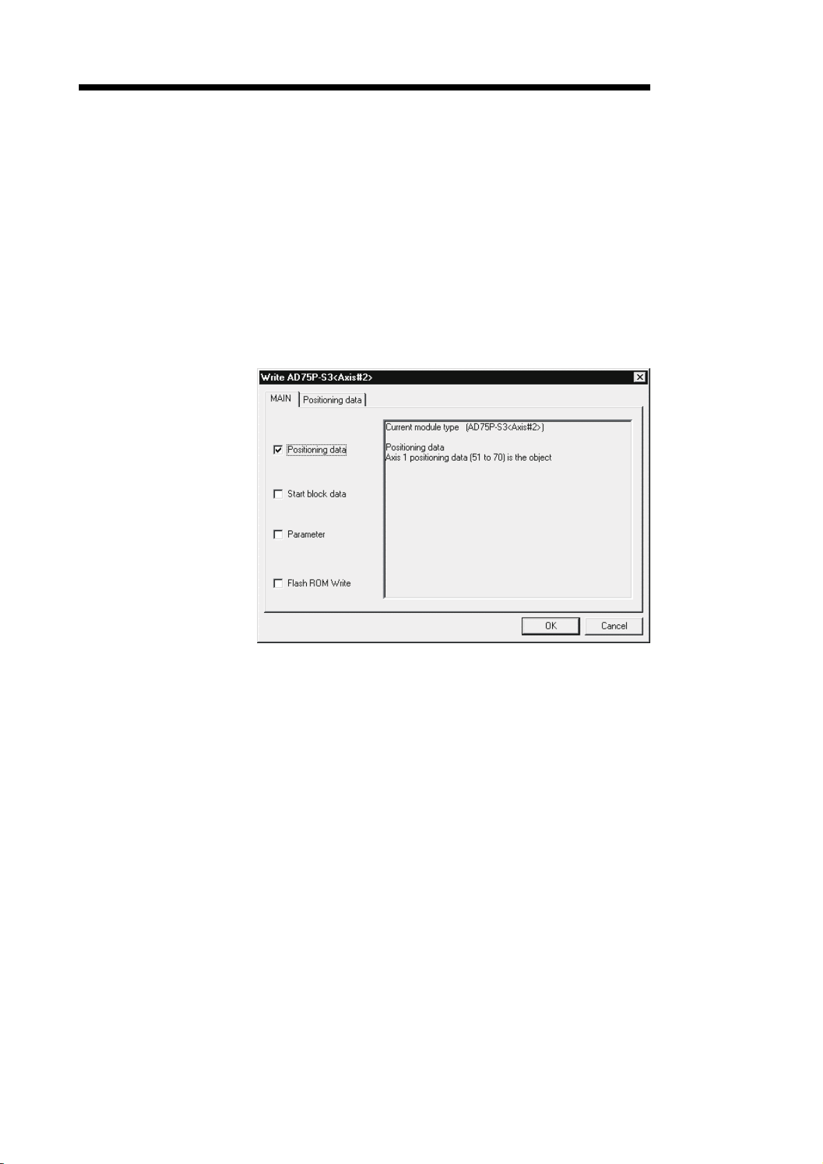
(8) Read from AD75/write to AD75/verify AD75 data can be performed
axis-by-axis on a data basis
GX Configurator-AP allows each of the positioning data, start block data and
parameters to be specified as the object of read from AD75/write to AD75/verify
AD75 data axis-by-axis.
Further, positioning data can be specified on a data No. basis, and block No. 0 of
start block data can be specified independently.
Hence, during debugging when data is written frequently for modification,
wasteful waiting time is greatly reduced to improve working efficiency.
[Write range is set to 2-axis positioning data No. 51 to 70]
1 - 6 1 - 6
Page 21
1. OVERVIEW
MELSOFT
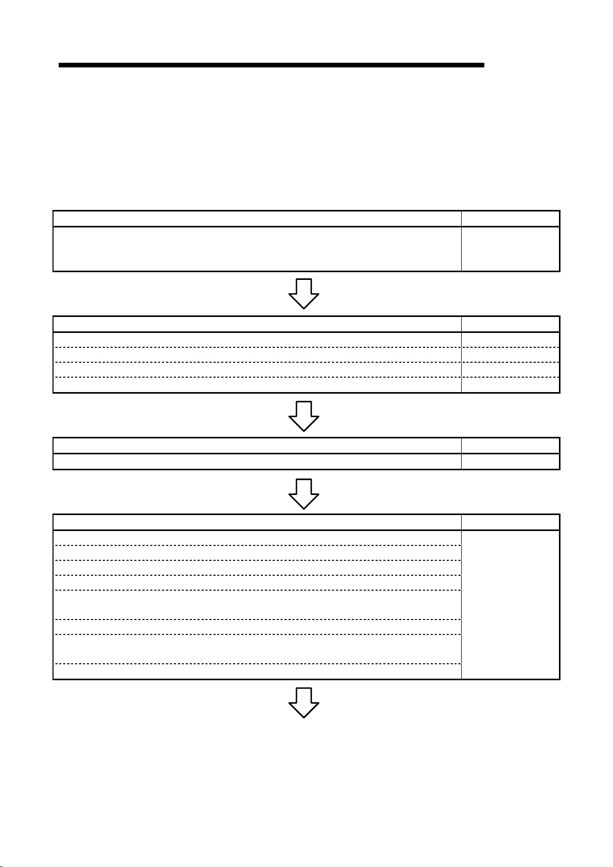
1.2 Manual Makeup
This manual is made up of 12 chapters and appendices.
This manual assumes that GX Configurator-AP is used to perform steps from
positioning system connection checking to operation in the following procedure.
Step 1: Install and wire the positioning system. Refer To
• Install and wire the programmable controller (such as the programmable controller CPU,
positioning module and I/O modules), servo amplifiers, motors, external switches and other
external devices.
Step 2: Check the GX Configurator-AP functions and learn the basic operation. Refer To
• Check the system with which GX Configurator-AP can be used. Chapter 2
• Check the functions that can be performed by GX Configurator-AP. Chapter 3
• Install GX Configurator-AP in the peripheral device and start the program. Chapter 4
• Learn the GX Configurator-AP screen makeup and basic operation. Chapter 5
Step 3: Start operation of GX Configurator-AP. Refer To
• Create a project which will be the object of operation performed on GX Configurator-AP. Chapter 6
Step 4: Check the connection and initial operation of the positioning system. Refer To
• Check the version of the positioning module.
• Check connection according to the signal states from the external devices..
• Check the alarm or warning of the positioning module.
• Check the alarm or warning of the servo amplifiers (AD75M only)
• Check that the initial settings are the same on the peripheral device and servo amplifiers.
(AD75M only)
• Check that the servomotors are run by JOG operation.
• Check that the upper/lower limit, DOG and zero point signals turned on/off by JOG operation.
(AD75M only)
• Check that the servomotor speed does not exceed the maximum speed. (AD75M only)
<Sequence of steps taken by the user up to positioning system operation>
AD75 User's Manual
Chapter 7
(To the next page)
1 - 7 1 - 7
Page 22
1. OVERVIEW
MELSOFT
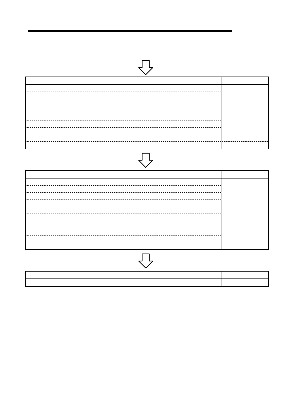
(From the preceding page)
Step 5: Set and write data to the positioning module. Refer To
• Set the parameters appropriate for the positioning system and control.
• Set the servo parameters appropriate for the specifications of the servo amplifiers and motors
used.
• Set the positioning data.
• Check the parameter, positioning data and start block data settings on the error check screen.
• Check the positioning data on the offline simulation (virtual positioning) screen.
• Make the corresponding setting if start block data, condition data, indirect data or M code
comment is required.
• Write the set data to the positioning module. Chapter 10
Chapter 8
Chapter 9
Step 6: Perform test operation and check and adjust the settings. Refer To
• Check positioning control and test on the monitor screen.
• Specify the positioning data and perform test operation.
• Specify the start block data and perform test operation.
• Make software limit test and error compensation by current value change, JOG operation or
manual pulse generator operation.
• Perform original position return test.
• Perform speed change test to find proper speed.
• If motor torque is not proper, perform torque control test to change the setting.
• Check undershoot, settling time and oscillation width in the test of position control gain 1 of servo
parameters. (AD75M only)
Chapter 11
Step 7: Positioning system operation. Refer To
• Operate the positioning system with the programmable controller CPU program. AD75 User's Manual
1 - 8 1 - 8
Page 23
2. SYSTEM CONFIGURATION
MELSOFT
2. SYSTEM CONFIGURATION
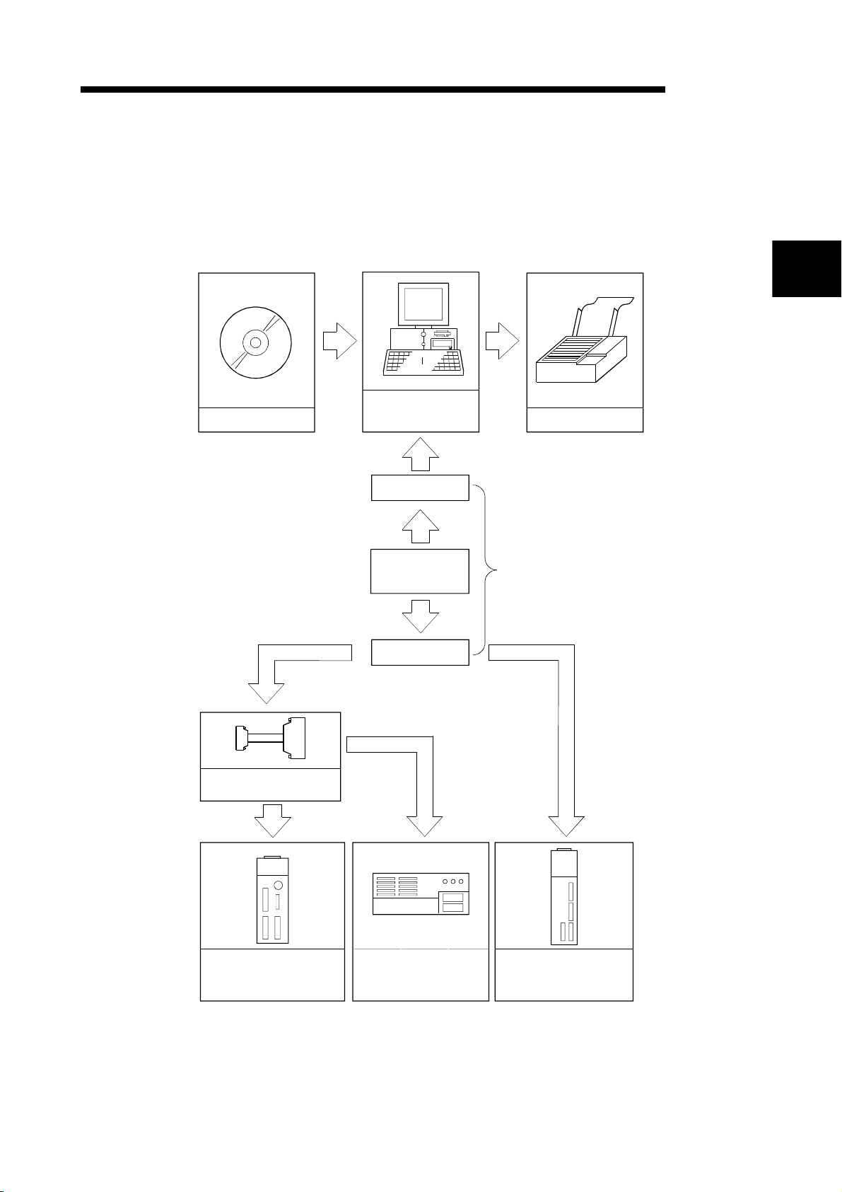
2.1 System Configuration
(1) Overall configuration of this system
GX Configurator-AP
Peripheral device
(Refer to Section 2.2)
RS-232 cable
2
Printer
Conversion cable
(A1SD75-C01HA)
A1SD75P1/P2/P3
A1SD75P1-S3/P2-S3/P3-S3
A1SD75M1/M2/M3
RS-232/RS-422
converter
RS-422 cable
AJ65BT-D75P2-S3
Refer to (2)
AD75P1/P2/P3
AD75P1-S3/P2-S3/P3-S3
AD75M1/M2/M3
2 - 1 2 - 1
Page 24
2. SYSTEM CONFIGURATION
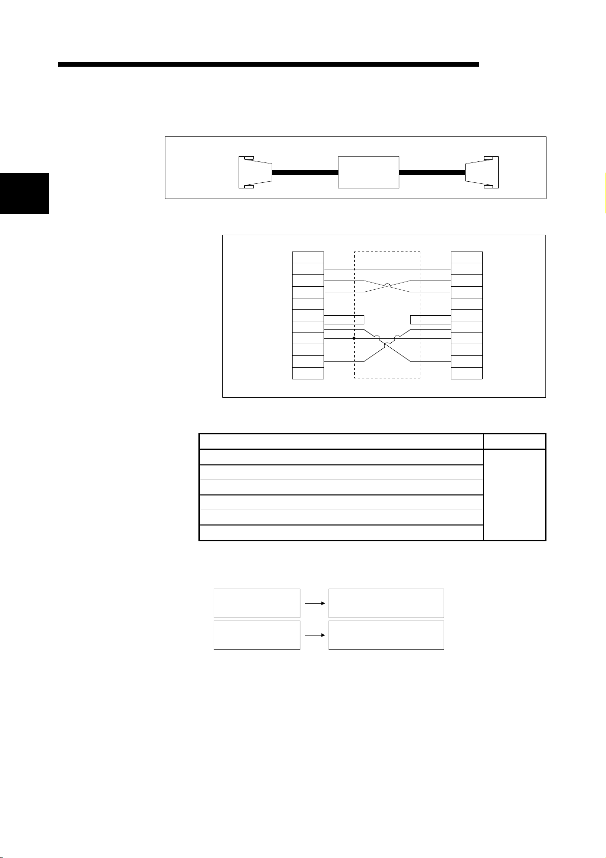
(2) About the RS-232 cable
2
For use of the FX-232AW(C) (Mitsubishi Electric make)
RS-232 RS-422
Peripheral
device side
FX-232AW(C)
RS-232 cable wiring
Peripheral device side
Pin No.
FG
1
TXD
2
RXD
3
RTS
4
CTS
5
DSR
6
SG
7
DTR
20
MELSOFT
Converter side
Pin No.
1
2
3
4
5
6
7
20
AD75 side
FG
TXD
RXD
RTS
CTS
DSR
SG
DTR
The following products of RS-232 and RS-422 cables are recommended.
Cable Maker
FX-232AW(C) (RS-232/RS-422 converter)
F2-232CAB*1 (when peripheral device has D-sub 25-pin connector)
F2-232CAB-1*1 (when peripheral device has D-sub 9-pin connector)
FX-422CAB (0.3m)
Shield
Mitsubishi
Electric
FX-422CAB-150 (1.5m)
AC30N2A (when peripheral device has D-sub 25-pin connector)
*1: To identify compatible products, check the type indicated on the cable's
type label.
Incompatible product
F2-232CAB
Y990C*****
F2-232CAB-1
Y990C*****
Compatible product (with F/FX/A)
F2-232CAB(F/FX/A)
Y990C*****
F2-232CAB-1(F/FX/A)
Y990C*****
2 - 2 2 - 2
Page 25

2. SYSTEM CONFIGURATION
• Before handling the RS-422 interface conversion cable/converter, please read its
specifications, precautions, etc. carefully in the manual of the corresponding
product and handle it correctly.
• When disconnecting or reconnecting the conversion cable/converter that receives
5VDC power from the RS-422 interface, switch power off on the programmable
controller side before starting work.
• When disconnecting or reconnecting the peripheral device or conversion cable that
does not receive 5VDC power from the RS-422 interface (whose power is
supplied from an external power supply), be sure to use an earth band or touch a
grounded metal object, etc. before starting work to discharge static electricity from
the cable, human body, etc. After that, handle it in the following procedure.
1) Switch power off on the personal computer side.
2) Power off the conversion cable/converter. When it has an FG terminal, ground
it.
3) Connect/disconnect the conversion cable/converter between the personal
computer and programmable controller CPU.
4) Power on the conversion cable/converter.
5) Power on the personal computer.
6) Start up GX Configurator-AP
MELSOFT
2 - 3 2 - 3
Page 26
2. SYSTEM CONFIGURATION
2.2 Operating Environment
MELSOFT
The operating environment of GX Configurator-AP is indicated below.
Item Description
Peripheral device Personal computer on which WindowsR operates.
Computer main unit
CPU
Required memory
Refer to the following table "Used operating system and performance required for
personal computer".
Hard disk free space 10MB or more 1
Disk drive CD-ROM disk drive
Display 800 × 600 dot or more resolution 2
Microsoft
R
WindowsR 95 Operating System
MicrosoftR WindowsR 98 Operating System
MicrosoftR WindowsR Millennium Edition Operating System
R
Microsoft
Windows NTR Workstation Operating System Version 4.0
MicrosoftR WindowsR 2000 Professional Operating System
Operating system
MicrosoftR WindowsR XP Professional Operating System
R
Microsoft
WindowsR XP Home Edition Operating System
MicrosoftR Windows VistaR Home Basic Operating System
MicrosoftR Windows VistaR Home Premium Operating System
R
Microsoft
Windows VistaR Business Operating System
MicrosoftR Windows VistaR Ultimate Operating System
MicrosoftR Windows VistaR Enterprise Operating System
1: At minimum, free space of 15GB is required for Windows VistaR.
2: Resolution 1024 × 768 pixels or higher is recommended for Windows VistaR.
WindowsR 95 (Service Pack 1 or more) PentiumR 133MHz or more 32MB or more
WindowsR 98 PentiumR 133MHz or more 32MB or more
WindowsR Me PentiumR 150MHz or more 32MB or more
Windows NTR Workstation 4.0 (Service Pack 3 or more) PentiumR 133MHz or more 32MB or more
WindowsR 2000 Professional PentiumR 133MHz or more 64MB or more
WindowsR XP Professional PentiumR 300MHz or more 128MB or more
WindowsR XP Home Edition PentiumR 300MHz or more 128MB or more
Windows VistaR Home Basic PentiumR 1GHz or more 1GB or more
Windows VistaR Home Premium PentiumR 1GHz or more 1GB or more
Windows VistaR Business PentiumR 1GHz or more 1GB or more
Windows VistaR Ultimate PentiumR 1GHz or more 1GB or more
Windows VistaR Enterprise PentiumR 1GHz or more 1GB or more
Used operating system and performance required for personal computer
Operating system
Performance Required for Personal Computer
CPU Required memory
2 - 4 2 - 4
Page 27
2. SYSTEM CONFIGURATION
The functions shown below are not available for WindowsRXP and Windows
R
Vista
.
If any of the following functions is attempted, this product may not operate normally.
Start of application in Windows
Fast user switching
Remote desktop
Large fonts (Details setting of Display Properties)
Also, 64-bit version Windows
Use a USER authorization or higher in Windows Vista
MELSOFT
R
compatible mode
R
XP and Windows VistaR are not supported.
R
.
2 - 5 2 - 5
Page 28

3. FUNCTION LIST
3. FUNCTION LIST
3.1 Function List
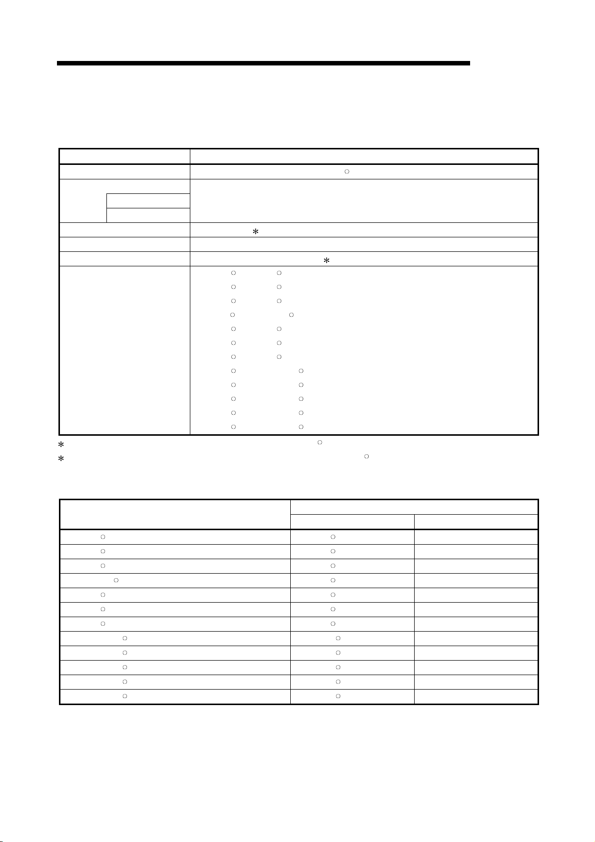
Mode Main Screen Function Description
Parameter Parameter setting
3
Edit
Monitor
Servo parameter
(AD75M only)
Positioning data
axis #1
Positioning data
axis #2
Positioning data
axis #3
Start block axis
#1
Start block axis
#2
Start block axis
#3
Operation
monitor (test)
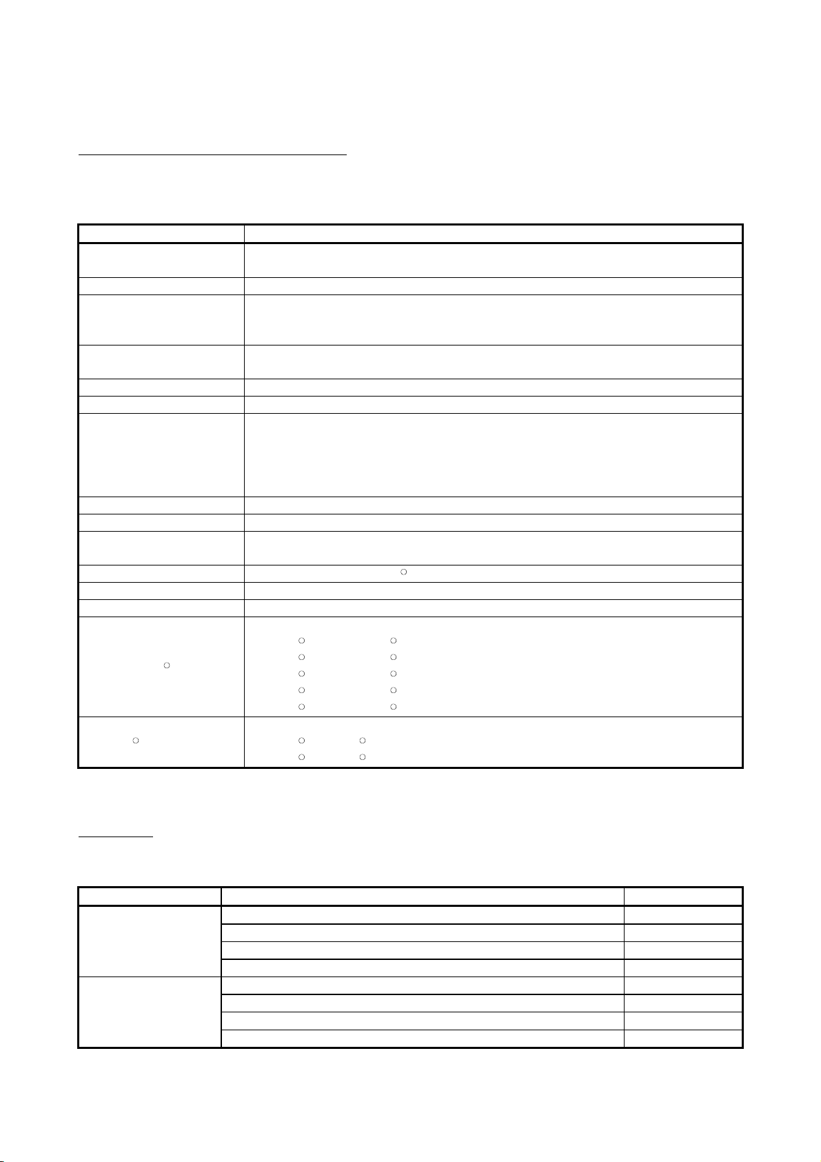
(1) Function list
GX Configurator-AP functions are listed below mode-by-mode.
Set the basic parameters1, basic parameters2, extended
parameters1, extended parameters2, OPR basic parameters and
OPR extended parameters on an axis basis.
Servo parameter
setting
Positioning data
setting
Positioning data
monitor
Positioning data test
Teaching
M code comment
setting
Offline simulation
Start block data
setting
Start block data
monitor
Start block data test
Condition data
setting
Indirect data setting
Operation monitor
(main screen)
History monitor
Signal monitor
Operation monitor
(dialog)
Servo monitor Monitor the servo amplifier and servomotor states of all axes.
Operation test
Set the servo basic parameters, servo adjustment parameters and
servo extension parameters on an axis basis.
Set the positioning data, such as pattern, control method,
accel/decel time and address, on an axis basis.
Monitor the positioning data during execution on an axis basis.
Perform test operation of positioning control on an axis or
positioning data basis.
Set the feed address of the moved axis to the address of
positioning data by JOG operation or the like.
Set comments to the M codes assigned to the positioni ng data on
an axis basis.
Assume axis operation from the set positioning data on an axis
basis.
Set the starting mode, etc. of the positioning data specified for
points on an axis basis.
Monitor the point at which positioning control is being executed on
an axis basis.
Perform test operation of positioning control from the point of the
specified block on an axis basis.
Set the data which is used as the starting condition of the start
block data on an axis basis.
Set the positioning data numbers set to the indirect designating
buffer memory of the AD75 on an axis basis.
Monitor the operating states, such as addresses, axis speeds, axis
statuses and executed positioning data numbers, of all axes.
Monitor the error, warning, start or error-time start history of all
axes.
Monitor the X/Y devices, external signals or status signals of all
axes.
Monitor the control states, AD75 parameter settings or others of all
axes.
Test the positioning data number-specified start, current value
change, speed change, original position return, JOG operation and
manual pulse generator operation of all axes.
MELSOFT
3 - 1 3 - 1
Page 29

3. FUNCTION LIST
Mode Main Screen Function Description
Monitor
Diagnosis
Trace*1
Sampling
monitor
AD75P checking
connect
(AD75P only)
AD75M servo
starting up
(AD75M only)
AD75M position
control gain
(AD75M only)
Wavy display Wavy display
Tracks displays Tracks displays
Sampling monitor
AD75P checking
connect
Initial check Monitor the error/warning history of the AD75M or servo amplifiers.
Module name
check
Upper/lower limit
check
RPM check
AD75M position
control gain
Monitor the specified signals and buffer memory data w hile
simultaneously sampling them.
Display signals from external devices. Also test initial operation by
JOG operation.
Compare the servo parameters read from the servo amplifiers to
the AD75M with the servo parameters on the peripheral device.
Judge the upper and lower limit switch operations by JOG
operation.
Display the motor speeds for JOG operation and the motor speeds
set to the servo basic parameters.
Adjust the servomotor characteristics such as response lev el and
settling time.
Trace the specified data (position instruction, servomotor sp eed,
etc.) for a given time and display the waveform data relative to the
time axis.
Trace the position command or real value for a given time and
display the track data of the axes.
MELSOFT
3
*1 The following positioning modules do not have the trace mode.
• AD75P1/P2/P3
• A1SD75P1/P2/P3
3 - 2 3 - 2
Page 30

3. FUNCTION LIST
Project
New Project
Open Project
Save Project
Save as Project
Delete Product
Verify Project
Import file
File reading of SW1RX/IVD/NX-AD75P
File reading of CSV form positioning data
File reading of trace data
Export file
File writing of SW1RX/IVD/NX-AD75P
File writing of CSV form positioning data
File writing of trace data
Change AD75 model
Print
Printer set u p
Latest file
Exit
Edit Cut
Copy
Paste
Select all
Jump
Clear row
Clear column
Axis copy
Start block copy
Positioning data input
Start block data input
Parameter data input
Servo parameter
M code comment
Condition data edit
Indirect data edit
Offline simulator
(2) Menu list
The menu bar drop-down menus are listed below.
Online
Tool Initialize data
Read from AD75
Write to AD75
Verify AD75 data
OS information
Flash-ROM request
Initialize AD75
Monitor
Monitor start
History monitor
Signal monitor
Operation monitor
Servo monitor
Test
Test start
Start condition
Operation Test
Teaching
All axis On/Off
Designate Off
Error Reset
Error Reset #1
Error Reset #2
Error Reset #3
M code Off
M code #1 Off
M code #2 Off
M code #3 Off
Initialize parameter
Initialize servo parameter
Register servo name
Error check
Option
MELSOFT
Designate #1 Off
Designate #2 Off
Designate #3 Off
View
Toolbar
Project toolbar
Edit toolbar
Online toolbar
Status bar
Change menu
Move upward
Select Axis
Axis #1
Axis #2
Axis #3
Select start block
Edit property dialog
Large Icons
Small Icons
List view
Detailed view
Help Error/Warning Help
List of Buffer memory
About
Connection to MELFANSweb
3 - 3 3 - 3
Page 31

4. INSTALLATION AND UNINSTALLATION
MELSOFT
4. INSTALLATION AND UNINSTALLATION
This chapter describes how to install and uninstallation of GX Configurator-AP.
4.1 Installation
This section explains the installation procedure and operation of GX Configurator-AP.
(1) Installation procedure
Install GX Configurator-AP in the following procedure.
New installation
Install the product.
Register the Name and Company.
Register the product ID.
Boot the application.
Check whether the product has been
installed properly.
Refer to
Section 4.1.
Refer to
Section 4.3.
4
Complete
(2) Installation operation
Check the following before starting installation.
• Before starting installation, close all other applications that are running on
Microsoft
R
WindowsR Operating System.
• The installer may not work normally because the update program of operating
system or other companies' software such as Windows Update and java update
may start automatically. Please install the driver after changing the setting of the
update program not to start automatically.
• When the following OS is being used, please logon as a user with the attribute of
Administrator.
Microsoft
Microsoft
Microsoft
Microsoft
Microsoft
Microsoft
Microsoft
Microsoft
Microsoft
R
Windows NTR Workstation Operating System Version 4.0
R
WindowsR 2000 Professional Operating System
R
WindowsR XP Professional Operating System
R
WindowsR XP Home Edition Operating System
R
Windows VistaR Home Basic Operating System
R
Windows VistaR Home Premium Operating System
R
Windows VistaR Business Operating System
R
Windows VistaR Ultimate Operating System
R
Windows VistaR Enterprise Operating System
4 - 1 4 - 1
Page 32

4. INSTALLATION AND UNINSTALLATION
Double-click here.
(a) Installing the product
The screens used for explanation in this section are those of MicrosoftR
Windows
R
98 Operating System.
1) Boot Windows
disk is inserted.
Double-click "Setup.exe".
To display Windows
[Programs] - [Windows Explorer].
: When user account control is enabled in Windows
R
Vista
, the following screen appears.
Click "Allow".
MELSOFT
®
Explorer and click the drive where the
®
Explorer, choose [Start] -
4
(To the next page)
2) If either of the left screens appears, perform operation in
accordance with the instructions given in (b).
After the operation is over, restart installation operation.
If the left screen appears, perform operation in accordance
with the instructions given in (c).
After the operation is over, restart installation operation.
If the left screen appears, perform operation in accordance
with the instructions given in (d).
After the operation is over, restart installation operation.
4 - 2 4 - 2
Page 33

4. INSTALLATION AND UNINSTALLATION
(From the preceding page)
3) Type the name and company, and click Next> .
4) Enter the product ID and click Next> .
MELSOFT
As the confirmation dialog box appears, follow the
message and perform operation.
The product ID is given in the "Software Registration
Card" packed with the product.
(To the next page)
5) Specify the installation destination folder.
Click Next> if the destination folder displayed is OK.
To change the folder, click Browse and specify a new
drive and folder.
: The following screen appears in Windows VistaR.
Click "Install this driver software anyway".
This screen may appear in several times.
4 - 3 4 - 3
Page 34

4. INSTALLATION AND UNINSTALLATION
(From the preceding page)
The either of the following screens may appear behind
MELSOFT
the Windows Security screen. Then, press the "Alt" +
"Tab" keys to bring it to the front.
Click "OK" on the following screens.
: For WindowsR XP, the following screen appears at
first installation.
Click "Continue".
We checked operations in Windows
R
XP (Problems
never occur after installation.)
The following screen may appear behind another
screen. Then, press the "Alt" + "Tab" keys to bring it
to the front.
6) This completes installation.
Click OK .
(To the next page)
4 - 4 4 - 4
Page 35

4. INSTALLATION AND UNINSTALLATION
(From the preceding page)
7) When the left screen appears on Windows Vista
(b) Installation of dcom95.exe or Axdist.exe
This section explains the updating operation of WindowsRusing
"Update\dcom95.exe" or "Update\Axdist.exe" on the CD-ROM.
Execute dcom95.exe or Axdist.exe provided for GX Configurator-AP.
Install GX Configurator-AP after executing the exe file and restarting the
IBM-PC/AT compatible.
The exe file to be executed on the corresponding operating system is
indicated below.
MicrosoftRWindowsR95 Operating System
Microsoft
MicrosoftRWindows NTRWorkstation Operating System Version 4.0 Axdist.exe
R
WindowsR98 Operating System
(dcom95.exe and Axdist.exe are in the "Update" folder on CD-ROM.)
MELSOFT
R
,
regardless of the installation result, choose "This
program installed correctly".
Do not choose "Reinstall using recommended settings",
because the installer installs an ncorrect module.
OS File name
dcom95.exe
Axdist.exe
4 - 5 4 - 5
Page 36

4. INSTALLATION AND UNINSTALLATION
(c) Installation of 50comupd.exe
This section explains the updating operation of Windows® using
"Update\50comupd.exe" on the CD-ROM.
1) Click the Yes button to start updating Windows.
2) Accept the agreement on the left screen and click
the Yes button.
MELSOFT
3) Click Yes to restart.
After a restart, perform the installation operation in (a).
4 - 6 4 - 6
Page 37

4. INSTALLATION AND UNINSTALLATION
(d) Installation of EnvMEL
When user account control is enabled in Windows VistaR, the following
screen appears. Click "Allow".
MELSOFT
: After executing the above exe file, install the product again. If this
product is not installed properly at this time, reboot the personal
computer.
When the following screen appears on Windows Vista
installation result, choose "This program installed correctly".
Do not choose "Reinstall using recommended settings", because the
installer installs an incorrect module.
R
, regardless of the
(e) Registered icon
The following icon is registered by installing GX Configurator-AP.
REMARK
When Windows® XP or Windows Vista® is used, the icons are registered to [Start] [All Programs] - [MELSOFT Application].
4 - 7 4 - 7
Page 38

4. INSTALLATION AND UNINSTALLATION
4.2 Uninstallation
This section provides the operation to delete GX Configurator-AP from the hard disk.
Uninstalling the GX Configurator-AP
1) Choose and double-click "Add/Remove Programs" in
(To the next page)
2) Choose " GX Configurator-AP ".
MELSOFT
the Control Panel.
To display the Control Panel, choose [Start] - [Setting] [Control Panel].
REMARKS
R
When using Windows
Programs" from the Control Panel.
When using Windows Vista
XP, choose "Add or Remove
R
, Chose "Uninstall a
program" from the Control Panel in.
To display the Control Panel, choose [Start] - [Control
Panel].
After making selection, click Add/Remove .
REMARKS
The screen shown on the left is that of WindowsR 98.
The displayed screen varies with the OS.
When using Windows
R
2000 Professional, WindowsR
XP, perform the following operation.
(a) Click "Change/Remove Programs".
(b) Click "GX Configurator-AP".
(c) Click the "Change/Remove".
: When user account control is enabled in Windows
R
Vista
, the following screen appears.
Click the "Continue" button.
4 - 8 4 - 8
Page 39

4. INSTALLATION AND UNINSTALLATION
(From the preceding page)
3) Confirm that GX Configurator-AP may be removed.
4) If the left screen has appeared, click the "No To All"
MELSOFT
When uninstalling the program, click the "Yes" button to
start uninstallation.
When not executing uninstallation, click the "No".button
to return to the previous screen.
*Components indicate the installed icon files.
button.
If you click the "Yes" or "Yes To All" button, the shared
file of the Windows
R
compatible MELSOFT software is
removed. Therefore, click the "No To All" button when
removing GX Configurator-AP only.
5) Click the "OK" button if the "Uninstall successfully
completed" message appears.
If a warning appears for the files that were not
removed, open "Explorer", click the files, and remove
unnecessary files.
Note that if you remove necessary files accidentally,
the other applications may not be booted.
4 - 9 4 - 9
Page 40

4. INSTALLATION AND UNINSTALLATION
4.3 Starting GX Configurator-AP
This section provides how to start GX Configurator-AP in the start menu.
↓
1) Click the Windows
cursor to [Programs
: [All Programs] appears when using WindowsR
XP.
2) Click [GX Configurator-AP].
R
MELSOFT
"Start" button and move the
] → [MELSOFT application].
↓
3) GX Configurator-AP starts.
4 - 10 4 - 10
Page 41

4. INSTALLATION AND UNINSTALLATION
4.4 Ending GX Configurator-AP
This section describes how to end GX Configurator-AP in the project menu.
(1) Menu-driven exit method
MELSOFT
Click the [Project]
GX Configurator-AP ends.
[Exit] menu.
(2) Title bar-driven exit method
Click
Alternatively, click
GX Configurator-AP cannot be exited while online status such as test mode, trace
mode, Write to AD75/Read from AD75/Verify AD75 Data is set.
Exit it with offline status.
and choose [Close].
at the right end of the title bar.
4 - 11 4 - 11
Page 42

4. INSTALLATION AND UNINSTALLATION
MEMO
MELSOFT
4 - 12 4 - 12
Page 43

5. SCREEN MAKEUP AND BASIC OPERATIONS
5. SCREEN MAKEUP AND BASIC OPERATIONS
5.1 Screen Makeup
This section provides the screen makeup and various tools of GX Configurator-AP.
MELSOFT
Title bar
Menu bar
Project toolbar Drop-down menu
Online toolbar
Edit toolbar
Screen minimize
button
Screen magnify/
reduce button
Screen close
button
5
Menu screen Status bar Main screen
5 - 1 5 - 1
Page 44

5. SCREEN MAKEUP AND BASIC OPERATIONS
5.2 Basic Operations (1) Menu screen
The menu screen is used to choose the mode and main screen type.
There are tree and image menu screens, either of which can be selected by
clicking the corresponding tab, <<Tree menu>> or <<Image menu>>.
MELSOFT
5
Tree menu
*1
*1
*1
*1
*1
Image menu
Edit mode*2
Monitor mode*2
Positioning data edit
Choose axis number with
any of connectors 1 to 3.
Operation monitor
Parameter edit
Diagnosis mode*2
Trace mode*2
*1 Double-clicking the module model name (AD75P-S3 <Axis #3> in the above
example) displays the menu of the mode selected on the main screen with an icon.
*2 Clicking the icon provides the same operation results as in *1.
Displaying the command box lists the menu items of the chosen mode.
The above diag ra m show s a displ ay exa mpl e p rov id ed w hen you cli c k [M on ito r ].
Remarks
Use the "F6" key to move the cursor from the main screen to the menu screen
through th e key boa r d .
To move the cursor from the menu screen to the main screen, move the cursor to
the <<Tree menu>>/<<Image menu>> tab on the menu screen and press the "F6"
key.
Operations described in Chapter 6 and later are those selected from the tree menu.
When performing any operation from the image menu, confirm the above
explanation before starting the operation.
5 - 2 5 - 2
Page 45

5. SCREEN MAKEUP AND BASIC OPERATIONS
(2) Basic operation for dialog box es
MELSOFT
1) Tab
2) List box
7) Spin box
1) Tab
Click the setting item name to select.
2) List box
Click to list choices, then click the item to be chosen.
3) Radio button
Click ! to choose one from among more than one selection item.
1) Tab
3) Radio
button
5) Check box
4) Text box
6) Command button
4) Text box
Type characters.
5) Check box
To execute any item, click " to check it off.
6) Command button
Click this button when executing "OK", "Cancel" or the like, or when
displaying the dialog box.
7) Spin box
Used either to type a value directly or to change a value by clicking
.
When typing a value directly, click inside the spin box and enter the
value from the keyboard.
When clicking
click
to decrease.
to change a value, click to increase the value, or
Remarks
When performing operation from the keyboard, choose the setting item with the
"Tab" key.
When there are two or more choices, use the "←", "→", "↑" and/or "↓" key.
5 - 3 5 - 3
Page 46

5. SCREEN MAKEUP AND BASIC OPERATIONS
(3) Shortcut key list
The following shortcut keys can be used on GX Configurator-AP.
MELSOFT
Shortcut Key
Ctrl + N New Project Ctrl + 1 Select Axis #1 Ctrl + O Open Project Ctrl + 2 Select Axis #2 Ctrl + S Save Project Ctrl + 3 Select Axis #3 Ctrl + P Print Ctrl + B Select start block Alt + F4 Exit - Ctrl + T Write to AD75
Ctrl + X Cut Ctrl + M Monitor start
Ctrl + C Copy Alt + 1 History Monitor Ctrl + V Paste Alt + 2 Signal Monitor Ctrl + A Select all - Alt + 3
Ctrl + J Jump - Alt + 4 Servo Monitor -
Ctrl + Y Clear row
Ctrl +
Backspace
Function (Corresponding
Menu Item)
Move upward -
Tool
Button
-
Shortcut Key
Function (Corresponding
Menu Item)
Operation Moni to r
Tool
Button
-
5 - 4 5 - 4
Page 47

6. PROJECT CREATION
6. PROJECT CREATION
A project is a collection of parameters, servo parameters (AD75M only), positioning
data and start block data.
MELSOFT
Project
<GX Configurator-AP project makeup>
Parameters (Axis #1 to #3)
There are basic parameters 1, basic parameters 2, extended parameters 1,
extended parameters 2, OPR basic parameters and OPR extended parameters.
Servo parameters (Axis #1 to #3: AD75M only)
Data transmitted from the AD75M to the servo amplifiers.
There are servo basic parameters, servo adjustment parameters and servo
expansion parameters.
Positioning data (Axis #1 to #3)
Data used to set the control data such as positioning control method and
addresses.
Data No. 1 to 600 can be set to each axis.
Start block data (Axis #1 to #3)
Data used to attach a condition to a positioning control start and set the repeat count.
6
When executing "New Project" or "Save as Project", you cannot use the following
characters and symbols in the project path and project name to be specified.
/ , : ; * " < > | \\ COM LPT AUX CON PRN NUL CLOCK$
6 - 1 6 - 1
Page 48

6. PROJECT CREATION
6.1 Creating a New Project
Set the AD75 model used to create a new project and the project items.
↓
MELSOFT
1) Click the [Project] → [New Project] menu (
2) Click the AD75 connected module "Reference"
button in the New project file dialog box.
).
6
↓
3) Choose the AD75 model name in the list box.
The AD75 Model and AD75 Axis select radio
buttons may also be used to make that selection.
4) Click the "OK" button.
↓
5) Set the project save path.
The project save path defaults to
C:\MELSEC\AD75WINE\USR.
When changing it, refer to "HELPFUL
OPERATION" on the next page.
6) Set the project name.
When specifying the project file name, you can
use a total of up to 150 characters to set the
project path and project name.
When setting the project path and project name,
the total number of characters should be within
150.
This screen assumes that the project name is
"SAMPLE".
7) Set the project title as required.
8) Click the "Create" button.
This creates a new project.
6 - 2 6 - 2
Page 49

6. PROJECT CREATION
Project saving destination and file name
If the project save path and project name described on the preceding page are
used to save the positioning data, the data is saved with the following file name
and extension.
C:\MELSEC\AD75WINE\USR\SAMPLE\SAMPLE.W75
Project save path Project name File name Extension*
HELPFUL OPERATION
You can perform the operation of changing the project save path while
simultaneously checking the project tree.
In step 5) on the preceding page, click the Project file set "Reference" button.
As the following dialog box appears, choose the project save path from the project
tree or type it from the keyboard.
This operation is also used to perform such operations as "Open Project", "Save
Project" and "Delete Project".
MELSOFT
* The extension is fixed (W75).
1) Choose the drive.
Click the "Create" button when creating a new project save path.
2) Choose/type a new project path.
Type a new project name.
3) Click.
6 - 3 6 - 3
Page 50

6. PROJECT CREATION
6.2 Opening the Existing Project
This section explains the operation of opening the saved project.
MELSOFT
1) Click the [Project] → [Open Project] menu (
↓
2) Click the name of the project you will open.
For the setting operation of referring to the save
path of the project to be opened, refer to
"HELPFUL OPERATION" in Section 6.1.
3) Click the "O pe n" but to n.
).
↓
4) The specified project opens.
6 - 4 6 - 4
Page 51

6. PROJECT CREATION
6.3 Saving the Project
PURPOSE
The project file which is currently edited is saved.
• Save
• Save as
MELSOFT
BASIC OPERATION
Click the [Project] → [Save Project] menu (
Click the [Project] → [Save as Project] menu.
When specifying the project file name, you can use a total of up to 150
characters to set the project path and project name.
When setting the project path and project name, the total number of characters
should be within 15 0.
For the operation of setting the project save path and project name, refer to
"HELPFUL OPERATION" in Section 6.1.
).
DISPLAY/SETTING SCREEN
6 - 5 6 - 5
Page 52

6. PROJECT CREATION
6.4 Deleting the Project
PURPOSE
The project is deleted from HD, FD or the like.
1. Click the [Project] → [Delete Project] menu.
2. In the Delete project file dialog box, choose the project you want to delete and
3. As the project file deletion confirmation dialog box appears, click the "Yes"
4. The project is deleted.
MELSOFT
BASIC OPERATION
click the "Delete" button.
Refer to Section 6.2 for the operation of changing the project path.
button.
DISPLAY/SETTING SCREEN
6 - 6 6 - 6
Page 53
6. PROJECT CREATION
6.5 Reading the Other Format File (Import file)
6.5.1 Reading the SW1∗-AD75P format file
PURPOSE
The positioning data, M code comments, start block data, condition data, indirect
data, parameters and servo parameters are read from the file saved on MS-DOS
version SW1∗-AD75P to the project of GX Gonfigurator-AP.
BASIC OPERATION
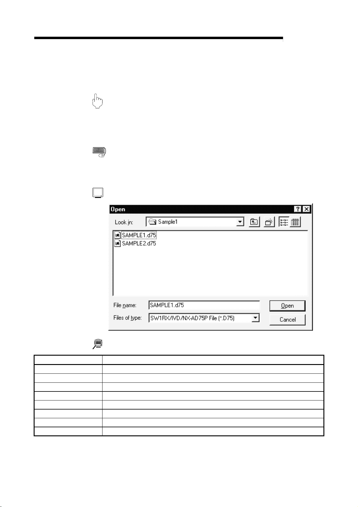
1. Click the [Project] → [Import file] → [File reading of SW1RX/IVD/NX-AD75P]
menu.
DISPLAY/SETTING SCREEN
MELSOFT
DISPLAY/SETTING DATA
Item Description
File, folder indication Show the folders existing in the specified drive or folder and the correspon ding ty pe of files.
File name Set the file name you will read.
Files of type Select SW1RX/IVD/NX-AD75P File (*.D75).
Look in Choose the drive or folder where the file you will read ex ists.
"Up one level folder" button C lick this b utton to show the folder one lev el abov e the currently displayed folder.
"List" button Click this button to list files and folders.
"Details" button Click this button to display the file and folder in detail.
"Open" button Click this button to read the file.
6 - 7 6 - 7
Page 54

6. PROJECT CREATION
6.5.2 Reading the CSV format file
PURPOSE
GX Configurator-AP allows CSV format files created with spreadsheet software or
the like to be read as positioning data (axis #1 to #3). (Parameters and start block
data cannot be read.)
The creating method and reading operation of CSV format data are described
below.
• If all items that make up positioning data have not been entered, CSV format data
cannot be read, resulting in an error.
• Since CSV format data is read axis-by-axis, create CSV format data noting which
axis (#1/#2/#3) data is being created.
MELSOFT
(1) CSV format data creating method
The following sheet indicates the items and values of CSV format data set on a
column basis. It should be noted that you cannot set the interpolation axis and
circular addresses for interpolation control.
<Example of data set to sp read she et so ftwa re>
1) 2) 3) 4) 5) 6) 7) 8) 9) 10)
<Data set to the above spreadsheet software was read with
GX Configurator-AP >
Num
ber
1) Line 1 from table top is positioning No. 1 data and line 2 is positioning No. 2 data.
2) Set the positioning control pattern in column 1 from left. Set any value of 0 to 2.
3) Set the control method in column 2 from left. Set it with 1 to 9 and A to I.
4) Set the accel time in column 3 from left. Set it with 0 to 3.
5) Set the decel time in column 4 from left. Set it with 0 to 3.
6) Set the address in column 5 from left.
7) Set the circular address in column 6 from left.
8) Set the command speed in column 7 from left.
9) Set the dwell time in column 8 from left.
10) Set the M code in column 9 from left.
Setting Remarks
Refer to Section
9.1 for details of
data
corresponding to
values and
alphabets to be
set.
6 - 8 6 - 8
Page 55

6. PROJECT CREATION
(2) CSV format file reading operation
BASIC OPERATION
1. Click the [Project] → [Import file] → [File reading of CSV form positioning data]
DISPLAY/SETTING SCREEN
MELSOFT
menu.
DISPLAY/SETTING DATA
Item Description
File, folder indication Show the folders existing in the specified drive or folder and the correspon ding ty pe of files.
File name Set the file name to be read to the project.
Choose the read positioning data of any of the axes.
To read the positioning data of axis #1
•
CSV File(1Axis)(*.CSV)
Files of type
Look in Choose the drive or folder where the file you will read ex ists.
"Up one level folder" button C lick this b utton to show the folder one lev el abov e the currently displayed folder.
"List" button Click this button to list files and folders.
"Details" button Click this button to display the file and folder in detail.
"Open" button Click this button to read the file.
To read the positioning data of axis #2
•
CSV File(2Axis)(*.CSV)
To read the positioning data of axis #3
•
CSV File(3Axis)(*.CSV)
6 - 9 6 - 9
Page 56

6. PROJECT CREATION
6.6 Write to Other Format File (Export file)
6.6.1 Saving in SW1∗-AD75P format file
PURPOSE
The positioning data, M code comments, start block data, condition data, indirect
data, parameters and servo parameters set on GX Configurator-AP are saved in
the MS-DOS version SW1∗ -AD75P format file.
BASIC OPERATION
1. Click the [Project] → [Export file] → [File writing of SW1RX/IVD/NX-AD75P]
menu.
DISPLAY/SETTING SCREEN
MELSOFT
DISPLAY/SETTING DATA
Item Description
File, folder indication Show the folders existing in the specified drive or folder and the correspon ding ty pe of files.
File name Set the file name to be saved in the other format file.
Save as type Select SW1RX/IVD/NX-AD75P File (*.D75).
Save in Choose the drive or folder where the file will be saved.
"Up one level folder" button C lick this b utton to show the folder one lev el abov e the currently displayed folder.
"Create New Folder"
button
"List" button Click this button to list files and folders.
"Details" button Click this button to display the file and folder in detail.
"Save" button Click this button to save the other format file.
6 - 10 6 - 10
Click this button to create a "new folder".
Page 57

6. PROJECT CREATION
6.6.2 Saving in CSV format file
PURPOSE
The positioning data set in the GX Configurator-AP project is saved in the CSV
format file.
Refer to Section 6.5.2 for the positioning data setting items and CSV format data.
BASIC OPERATION
1. Click the [Project] → [Export file] → [File writing of CSV form positio ni ng data]
menu.
DISPLAY/SETTING SCREEN
MELSOFT
DISPLAY/SETTING DATA
Item Description
File, folder indication Show the folders existing in the specified drive or folder and the correspon ding ty pe of files.
File name Set the file name to be read to the project.
Choose the saved positioning data of any of the ax es.
To save the positioning data of axis #1
•
CSV File(1Axis)(*.CSV)
To save the positioning data of axis #2
Save as type
Save in Choose the drive or folder where you will save the data.
"Up one level folder" button C lick this b utton to show the folder one lev el abov e the currently displayed folder.
"Create New Folder"
button
"List" button Click this button to list files and folders.
"Details" button Click this button to display the file and folder in detail.
"Save" button Click this button to save the other format file.
6 - 11 6 - 11
•
CSV File(2Axis)(*.CSV)
To save the positioning data of axis #3
•
CSV File(3Axis)(*.CSV)
Click this button to create a "new folder".
Page 58

7. SYSTEM CHECKING FROM PERIPHERAL DEVICE
7. SYSTEM CHECKING FROM PERIPHERAL DEVICE
MELSOFT
7
On the peripheral device, check the connection of the AD75 and external devices
(servo amplifiers, servomotors, etc.) and perform the initial operation test of
servomotors.
For the AD75M, operation tests can be made on the peripheral device to check the
servo amplifier status and servo parameters and further to check that the servo
parameters are valid.
• When the model used is the AD75P1/P2/P3, A1SD75P1/P2/P3, AD75P1-S3/P2S3/P3-S3 or A1SD75P1-S3/P2-S3/P3/S3, perform the following operation.
Section 7.1 Checking the AD75 Module Version (OS Information)
Section 7.2 AD75P Checking Connect
• When the model used is the AJ65BT-D75P2-S3, perform the following operation.
Section 7.2 AD75P Checking Connect
• When the model used is the AD75M1/M2/M3 or A1SD75M1/M2/M3, perform the
following operation.
Section 7.1 Checking the AD75 Module Version (OS Information)
Section 7.3 AD75M Servo Starting Up
Section 7.3.1 Servo initial check
Section 7.3.2 Servo model name check
Section 7.3.3 Servo upper/lower limit check
Section 7.3.4 Servo speed check
Before starting the OS information checking, AD75P checking connect or AD75M
servo starting up, make COM setting using the optional function (refer to Section
12.5).
If the COM setting is incorrect, a communication error will occur.
To check the usable COM port, perform the following operation.
1) Click the Microsoft
[Setting] → [Control Panel].
2) As the control panel opens, choose "System".
3) As the system property dialog box opens, choose the <<Device Manager>> tab.
4) Choose "Ports (COM & LPT)" and check the usable COM port.
R
WindowsR Operating System "Start" button and choose
7 - 1 7 - 1
Page 59

E
N
7. SYSTEM CHECKING FROM PERIPHERAL DEVICE
7.1 Checking the AD75 Module Version (OS Information)
PURPOS
Depending on the software version of the AD75 module, the parameters and some
functions cannot be used.
Before setting various data, check the software version of the module on the
peripheral device.
MELSOFT
1. Click the [Online] → [OS information] menu.
2. Check the software version in the OS information dialog box.
3. To exit, click the "Close" button.
DISPLAY/SETTING SCREEN
BASIC OPERATIO
DISPLAY/SETTING DATA
Item Description
Current connected module Indicates the model of the AD75 connected.
Current OS Indicates the OS name of the AD75 connected.
Indicates the software version of the AD75 connected.
Current version
The parameters and some functions cannot be used depending on the software version of
the AD75.
Refer to Appendix 2 for differences between the software versions of the AD75.
7
7 - 2 7 - 2
Page 60

E
N
7. SYSTEM CHECKING FROM PERIPHERAL DEVICE
7.2 AD75P Checking Connect
MELSOFT
PURPOS
Make sure that the cables between AD75P and servo amplifiers and between
servomotors, servo amplifiers and external devices are connected properly.
BASIC OPERATIO
1. Power on the positioning system and STOP the programmable controller CPU.
2. Choose AD75P Checking connect.
3. The online processing (test mode shift ) confirmation dialog box appears.
Click the "Initialize" button to check connection after initializing the AD75P.
Click "OK" to check connection without initializing the AD75P.
4. Make sure that the external I/O signals are in the following states on the AD75P
checking connect main screen.
Drive unit ready, Upper limit, Lower limit: z (ON)
Stop: { (OFF)
If any of the above states is not established, refer to "HELPFUL CORRECTIVE
ACTIONS" in this section.
5. Check whether the following signals from the external devices are ON or OFF.
Stop, External start, V/P switch, Deviation counter clr
6. Set the JOG speed.
7. Choose the arrow (
8. Move the mouse pointer (
the mouse or press the space key on the keyboard to start JOG operation.
Hold down the mouse's left button or the space key to continue JOG operation.
9. Perform JOG operation and check the operation, rotation direction and axis
speed of the servomotor.
10.Perform JOG operation and check whether Zero phase, In-position signal and
DOG turn on or off and the position (feed address) where each signal turns on.
11.Perform JOG operation and check whether the upper and lower limit switches
turn on or off.
Refer to Section 7.3.3 for the way of restoring an axis stop due to OFF of the
upper/lower limit switch.
12.When an error has occurred, check the error code with the help function (refer
to Section 12.11), then click [Online] → [Error Reset] → [Error Reset #1](
)/[Error Reset #2](
13.To exit, click the "OFF-LINE" button and click the "OK" button in the test mode
end confirmation dialog box.
Double-click.
Double-click.
) of the JOG operation direction.
) to the chosen arrow and press the left button of
)/[Error Reset #3]( ) menu.
7 - 3 7 - 3
Page 61

N
7. SYSTEM CHECKING FROM PERIPHERAL DEVICE
MELSOFT
DISPLAY/SETTING SCREE
DISPLAY/SETTING DATA
Item Description
External I/O Indicates the external I/O signal states (z: ON, {: OFF) of the AD75P.
JOG speed Set the speed for JOG operation.
Choose the arrow (
JOG direction
Operation monitor Indicates the feed addresses, axis speeds, error codes and warning codes of the axes.
"OFF-LINE" button Click this button to end the AD75P test mode and end AD75P checking connect.
"ON-LINE" button Click this button to start the AD75P test mode and execute AD75P checking connect.
button or the space key to start JOG operation.
The arrow is red during operation.
) of the axis for JOG operation and press the mouse's left
7 - 4 7 - 4
Page 62

7. SYSTEM CHECKING FROM PERIPHERAL DEVICE
MELSOFT
HELPFUL CORRECTIVE ACTIONS
Take the following corrective actions when AD75P checking connect cannot be
Status Corrective Action
AD75P checking connect
cannot start
Drive unit ready is OFF
Upper/lower limit is OFF
JOG operation cannot be
performed.
Error/warning occurred Check the error/warning code using [Help], and check and remove the cause.
completed properly.
Check the connection of cables with the AD75P.
Using the optional function (refer to Section 12.5), check whether COM setting is correct.
Check that the servo amplifier is powered.
Check the connection of the external I/O signal connector.
Check the connection of the external I/O signal connector.
Check for contact of the upper/lower limit switch.
Check that JOG speed setting is not "0".
7 - 5 7 - 5
Page 63

7. SYSTEM CHECKING FROM PERIPHERAL DEVICE
7.3 AD75M Servo Starting Up
With the AD75M servo starting up function, check the following.
• Error/warning history read from the AD75M
• Servo parameters of the servo amplifiers and project
• Operations of the upper/lower limit switches by JOG operation
• Motor speeds set to the servo parameters
The AD75M servo starting up function requires some servo parameters to be set and
write operation to AD75M to be performed in advance.
(1) Setting the servo parameters
Using the Initialize servo parameter wizard (refer to Section 12.4.2), set the servo
parameters.
For the setting data of the servo parameters, refer to positioning module type
A1SD75M1/M2/M3, AD75M1/M2/M3 User's Manual and the servo amplifier or
servomotor installation guide and instruction manual.
[Initialize servo parameter wizard dialog box]
MELSOFT
(2) Writing the servo parameters to the AD75M
For write, refer to Section 10.1.
[Write dialog box]
7 - 6 7 - 6
Page 64

E
N
7. SYSTEM CHECKING FROM PERIPHERAL DEVICE
7.3.1 Servo initial check
MELSOFT
PURPOS
The history of errors/warnings that occurred in the AD75M or servo amplifiers is
read from the AD75M and checked.
BASIC OPERATIO
1. Choose AD75M Servo starting up.
2. Click the "OK" button in the AD75M test mode start confirmation dialog box.
3. Click the <<Initial check>> tab on the AD75M servo starting up main screen.
4. Check for errors and warnings on the initial check screen.
If any errors and warnings have occurred, check the causes and corrective
actions using the help function (refer to Section 12.11) and remove the causes.
5. To exit, click the "Servo end" button and click the "OK" button in the test mode
end confirmation dialog box.
Double-click.
Double-click.
DISPLAY/SETTING SCREEN
7 - 7 7 - 7
Page 65

7. SYSTEM CHECKING FROM PERIPHERAL DEVICE
MELSOFT
DISPLAY/SETTING DATA
Item Description
No.
AX Indicates the axis where an error/warning was detected.
Type Indicates the type of the error or warning.
Source
Code Indicates the error/warning code detected.
Time
"Servo end"/"Online"
button
Indicates the order of errors/warnings detected.
Newer errors/warnings are displayed from top to bottom.
Indicates the source of error/warning occurrence.
The destination is the servo amplifier or AD75M.
Indicates the error/warning occurrence time in 100mm increments with reference to the time
set to the AD75 in the sequence program.
For time setting, refer to the AD75 User's Manual.
Click the "Servo end" button to end the AD75M test mode and terminate the initial check.
Click the "Online" button to place the AD75M in the test mode and read the error/warning
history from the AD75M.
7 - 8 7 - 8
Page 66

E
N
7. SYSTEM CHECKING FROM PERIPHERAL DEVICE
7.3.2 Servo model name check
MELSOFT
PURPOS
The servo basic parameters of the currently open project and the servo basic
parameters read from the servo amplifiers by the AD75M are displayed to make
sure that their settings are the same.
BASIC OPERATIO
1. Choose AD75M Servo starting up.
2. Click the "OK" button in the AD75M test mode start confirmation dialog box.
3. Click the <<Model name check>> tab on the AD75M servo starting up main
screen.
4. Check whether the servo basic parameters of the servo amplifier and peripheral
device are the same axis-by-axis.
5. If any servo parameter mismatch is found, write the parameters to the AD75M
(refer to Section 10.1).
6. To exit, click the "Servo end" button and click the "OK" button in the test mode
end confirmation dialog box.
Double-click.
Double-click.
DISPLAY/SETTING SCREEN
7 - 9 7 - 9
Page 67

7. SYSTEM CHECKING FROM PERIPHERAL DEVICE
MELSOFT
DISPLAY/SETTING DATA
Item Description
Indicates the setting items of the servo basic parameters compared on the AD75M and
Servo basic parameters
Ax1 of AD75 Indicates the servo basic parameters of axis #1 read from the servo amplifier to the AD75M.
Ax1 of peripheral Indicates the servo basic parameters of axis #1 set to the project on the peripheral device.
Ax2 of AD75 Indicates the servo basic parameters of axis #2 read from the servo amplifier to the AD75M.
Ax2 of peripheral Indicates the servo basic parameters of axis #2 set to the project on the peripheral device.
Ax3 of AD75 Indicates the servo basic parameters of axis #3 read from the servo amplifier to the AD75M.
Ax3 of peripheral Indicates the servo basic parameters of axis #3 set to the project on the peripheral device.
"Reload" button
"Servo end"/"Online"
button
peripheral device.
For the setting items of the servo basic parameters, refer to Positioning module type
A1SD75M1/M2/M3, AD75M1/M2/M3 User's Manual.
When executing the servo starting up function, click this button to read the servo basic
parameters again from the servo amplifiers.
Click the "Servo end" button to end the AD75M test mode and terminate the model name
check.
Click the "Online" button to place the AD75M in the test mode and enable reread.
7 - 10 7 - 10
Page 68

E
N
7. SYSTEM CHECKING FROM PERIPHERAL DEVICE
7.3.3 Servo upper/lower limit check
MELSOFT
PURPOS
Perform forward or reverse JOG operation to make sure that the upper and lower
limit switches installed in the positioning system operate properly.
BASIC OPERATIO
1. Choose AD75M Servo starting up.
2. Click the "OK" button in the AD75M test mode shift confirmation dialog box.
3. Click the <<U/L limit check>> tab on the AD75M servo starting up main screen.
4. Make sure that the signals are in the following states.
Servo, Ready, Upper limit, Lower limit: z (ON)
Alarm, Stop: { (OFF)
5. Set the JOG speed.
6. Choose the arrow (
7. Move the mouse pointer (
the mouse or press the space key on the keyboard to start JOG operation.
Hold down the mouse's left button or the space key to execute JOG operation.
8. Perform JOG operation to move the axis into contact with the upper/lower limit
switch, and make sure that "OK" appears at Upper or Lower limit.
9. To exit, click the "Servo end" button and click the "OK" button in the test mode
end confirmation dialog box.
Double-click.
Double-click.
) of the JOG operation direction.
) to the chosen arrow and press the left button of
7 - 11 7 - 11
Page 69

N
7. SYSTEM CHECKING FROM PERIPHERAL DEVICE
MELSOFT
DISPLAY/SETTING SCREE
DISPLAY/SETTING DATA
Item Description
Servo status
External I/O
JOG speed Set the speed for JOG operation.
JOG operation
Upper limit
Lower limit
JOG speed limit
Acc
Dec
Upper stroke limit
Lower stroke limit
Address
Speed
Error
Warning
"Data clear" button When rechecking the upper or lower limit, click this button to clear the result.
"Servo end"/"Online"
button
Indicates the states of the signals from external devices connected to the AD75M.
Choose the arrow (
button or the space key to start JOG operation.
The arrow is red during operation.
"OK" appears when the upper or lower limit signal turns off during JOG operation.
Indicates the JOG speed limit values, JOG speed accel times and JOG speed decel times
set to extended parameters 2 (refer to Section 8.1.4).
Indicates the software stroke upper and lower limits set to extended parameters 1 (refer to
Section 8.1.3).
Indicates the feed addresses, axis speeds, error codes and warning codes of the axes.
Click the "Servo end" button to end the AD75M test mode and terminate the upper/lower limit
check.
Click the "Online" button to place the AD75M in the test mode and start the upper/lower limit
check.
) of the axis for JOG operation and press the mouse's left
7 - 12 7 - 12
Page 70

7. SYSTEM CHECKING FROM PERIPHERAL DEVICE
MELSOFT
HELPFUL OPERATION
When the upper/lower limit switch is turned off by JOG operation, the
corresponding axis stops. To restart the axis, perform the following operation.
1. Click [Online] → [Error Reset] → [Error Reset #1](
)/[Error Reset #3](
) menu.
)/[Error Reset #2](
2. Perform JOG operation to move the axis to within the upper or lower limit range.
HELPFUL CORRECTIVE ACTIONS
Take the following corrective actions when the upper/lower limit check cannot be
Status Corrective Action
Servo signal is OFF
Ready signal is OFF
Alarm signal is ON Take the corrective action given in the servo amplifier installation guide.
Upper/lower limit is OFF
Stop signal is ON Turn off the external stop signal.
JOG operation cannot be
performed.
Error/warning occurred
made.
Check that the servo amplifier is powered.
Check the connection of the external I/O signal connector.
Check that the servo amplifier is powered.
Check the connection of the external I/O signal connector.
Check the connection of the external I/O signal connector.
Check for any object in contact with the upper/lower limit switch.
Check that JOG speed setting is not "0".
Check the error/warning code using [Help] (refer to Section 12.11), and check and remove
the cause.
7 - 13 7 - 13
Page 71

E
N
7. SYSTEM CHECKING FROM PERIPHERAL DEVICE
7.3.4 Servo speed check
MELSOFT
PURPOS
Perform forward/reverse JOG operation to make sure that the servomotor speed
does not exceed the motor speed set in the servo parameter.
BASIC OPERATIO
1. Choose AD75M Servo starting up.
2. Click the "OK" button in the AD75M test mode shift confirmation dialog box.
3. Click the <<RPM check>> tab on the AD75M servo starting up main screen.
4. Make sure that the signals are in the following states.
Servo, Ready, Upper limit, Lower limit: z (ON)
Alarm, Stop: { (OFF)
5. Set the JOG speed.
6. Choose the arrow (
direction.
7. Move the mouse pointer (
the mouse or press the space key on the keyboard to start JOG operation.
Hold down the mouse's left button or the space key to execute JOG operation.
8. Perform JOG operation, and check that the Max. For. and Max. Rev. speeds
are not more than their parameter settings.
9. To exit, click the "Servo end" button and click the "OK" button in the test mode
end confirmation dialog box.
Double-click.
Double-click.
:Forward :Reverse ) of the JOG operation
) to the chosen arrow and press the left button of
7 - 14 7 - 14
Page 72

N
7. SYSTEM CHECKING FROM PERIPHERAL DEVICE
MELSOFT
DISPLAY/SETTING SCREE
DISPLAY/SETTING DATA
Item Description
Servo status
External I/O
JOG speed Set the speed for JOG operation.
JOG operation
Param. Indicates the motor speeds set to the servo basic parameters (refer to Section 8.2.1)
RPM Indicates the current servomotor speeds.
Max. For. Indicates the servomotor maximum speeds in the forward direction.
Max. Rev. Indicates the servomotor maximum speeds in the reverse direction.
JOG speed limit
Acc.
Dec.
Address
Speed
Error
Warning
"Data clear" button Click this button to clear the maximum forward and reverse speed values.
"Servo end"/"Online"
button
Indicates the states of the signals from external devices connected to the AD75M.
Choose the arrow (
button or the space key to start JOG operation.
The arrow is red during operation.
Indicates the JOG speed limit values, JOG speed accel times and JOG speed decel times
set to extended parameters 2 (refer to Section 8.1.4).
Indicates the feed addresses, axis speeds, error codes and warning codes of the axes.
Click the "Servo end" button to end the AD75M test mode and terminate the speed check.
Click the "Online" button to place the AD75M in the test mode and start the speed check.
) of the axis for JOG operation and press the mouse's left
7 - 15 7 - 15
Page 73

7. SYSTEM CHECKING FROM PERIPHERAL DEVICE
MELSOFT
HELPFUL CORRECTIVE ACTIONS
Status Corrective Action
Servo signal is OFF
Ready signal is OFF
Alarm signal is ON Take the corrective action given in the servo amplifier installation guide.
Upper/lower limit is OFF
Stop signal is ON Turn off the external stop signal.
JOG operation cannot be
performed.
Error/warning occurred
Take the following corrective actions when the speed check cannot be made.
Check that the servo amplifier is powered.
Check the connection of the external I/O signal connector.
Check that the servo amplifier is powered.
Check the connection of the external I/O signal connector.
Check the connection of the external I/O signal connector.
Check for any object in contact with the upper/lower limit switch.
Check that JOG speed setting is not "0".
Check the error/warning code using [Help] (refer to Section 12.11), and check and remove
the cause.
7 - 16 7 - 16
Page 74

8. PARAMETER SETTING
8. PARAMETER SETTING
Set the parameters necessary to exercise positioning control.
There are parameters required for the AD75P and AD75M and those required for the
AD75M only.
Write the set parameters to the AD75 before starting positioning operation.
For the operation of writing data to the AD75, refer to Section 10.1.
For the setting data, refer to the AD75 User's Manual.
8.1 Parameters
PURPOSE
There are the following four parameter types.
• Basic parameters
• Extended parameters
• OPR basic parameters
• OPR extended parameters
The basic and extended parameters are divided into parameters 1 needed for
system start and parameters 2 optimized according to the connected external
devices and control.
Set each paramet e r ty pe in th e Pa ramet e r edit dialog box.
Perform the foll ow in g op era tion until the Pa ra met er ed it dia lo g bo x ap pe a rs.
MELSOFT
8
BASIC OPERATION
1. Choose Parameter.
Double-click.
Double-click.
2. Double-click any item in the column of the axis to be set on the parameter main
screen.
Double-click any item in this column to set the axis #2 parameters.
Double-click any item in this column Double-click any item in this column
to set the axis #1 parameters. to set the axis #3 parameters.
3. As the Paramet e r edit dialog box appear s, cli ck th e co rr esp ondin g tab to di splay
the setting screen.
4. Set the screen data on the display/setting screen shown in any of Sections 8.1.1
to 8.1.6.
5. To exit, click the "OK" button.
8 - 1 8 - 1
Page 75

8. PARAMETER SETTING
HELPFUL OPERATION
Perform the following operation when you want to return the parameters to the
initial values type-by-type to modify the positioning system.
1. Perform the ba si c ope rat i o n to di splay the Paramete r edi t di alo g bo x.
2. Click the "Initial value" button.
3. Using the check boxes, set the parameters to be initialized on the Parameter
4. Click the "OK" button to return the settings of the checked parameters to the
MELSOFT
edit dialog box tab screen basis.
initial values.
8 - 2 8 - 2
8
Page 76

8. PARAMETER SETTING
8.1.1 Basic parameter 1 setting screen
DISPLAY/SETTING SCREEN
MELSOFT
(Screen example: Screen displayed when AD75P#-S3 was selected in Change AD75 model)
8 - 3 8 - 3
Page 77

8. PARAMETER SETTING
8.1.2 Basic parameter 2 setting screen
DISPLAY/SETTING SCREEN
MELSOFT
(Screen example: Screen displayed when AD75P#-S3 was selected in Change AD75 model)
8 - 4 8 - 4
Page 78

8. PARAMETER SETTING
8.1.3 Extended parameter 1 setting screen
DISPLAY/SETTING SCREEN
MELSOFT
(Screen example: Screen displayed when AD75P#-S3 was selected in Change AD75 model)
(Screen example: Screen displayed when AD75P#-S3 was selected in Change AD75 model)
8 - 5 8 - 5
Page 79

8. PARAMETER SETTING
8.1.4 Extended parameter 2 setting screen
DISPLAY/SETTING SCREEN
MELSOFT
(Screen example: Screen displayed when AD75P#-S3 was selected in Change AD75 model)
(Screen example: Screen displayed whe n AD75M# was selected in Change AD75 model)
8 - 6 8 - 6
Page 80

8. PARAMETER SETTING
8.1.5 OPR basic parameter setting scr een
DISPLAY/SETTING SCREEN
MELSOFT
(Screen example: Screen displayed when AD75P#-S3 was selected in Change AD75 model)
8 - 7 8 - 7
Page 81

8. PARAMETER SETTING
8.1.6 OPR extended parameter setting scr een
DISPLAY/SETTING SCREEN
MELSOFT
(Screen example: Screen displayed when AD75P#-S3 was selected in Change AD75 model)
8 - 8 8 - 8
Page 82

8. PARAMETER SETTING
8.2 Servo Parameters
PURPOSE
Set the servo parameters transferred from the AD75M to the servo amplifiers over
the SSCNET (Servo System Controller NETwork).
There are the following three servo parameter types.
• Servo basic parameters
• Servo adjustment parameters
• Servo extension parameters
Set each servo par amet e r type in the Servo pa ra met er edi t di alo g box.
Perform the following operat i on un til th e Se rvo pa r a mete r edi t di al og bo x appe a rs.
For the setting data, refer to the installation guide or instruction manual of the
servo amplifier and servomotor used.
BASIC OPERATION
MELSOFT
1. Choose Servo pa r a mete r .
Double-click.
Double-click.
2. Double-click any item in the column of the axis to be set on the servo parameter
main screen.
Double-click any item in this column to set the axis #2 servo parameters.
Double-click any item in this column Double-click any item in this column
to set the axis #1 servo parameters. to set the axis #3 servo parameters.
3. As the Servo pa ra met e r ed it dialog box ap pe a rs, cli ck th e cor re sp o nding ta b to
display the setting screen.
4. Set the screen data on the display/setting screen shown in any of Sections 8.2.1
to 8.2.3.
5. To exit, click the "OK" button.
8 - 9 8 - 9
Page 83

8. PARAMETER SETTING
HELPFUL OPERATION
Perform the following operat i on to ret u rn th e se rv o pa ra met e rs to the ini ti al v a lue s
type-by-type.
1. Clicking the "Initial value" button displays the Servo parameter Initialization
2. Click the serv o par a mete r type to be initialized.
3. Click the "OK" button to return the checked parameter type to the initial values.
MELSOFT
dialog box.
8.2.1 Servo basic parameter setting scr een
DISPLAY/SETTING SCREEN
(Screen example: Screen displayed when Other was selected in Servo series)
8 - 10 8 - 10
Page 84

8. PARAMETER SETTING
8.2.2 Servo adjustment parameter setting screen
DISPLAY/SETTING SCREEN
MELSOFT
(Screen example: Screen displayed when Other was selected in Servo series)
(Screen example: Screen displayed when Other was selected in Servo series)
8 - 11 8 - 11
Page 85

8. PARAMETER SETTING
8.2.3 Servo extension parameter setti ng screen
DISPLAY/SETTING SCREEN
MELSOFT
(Screen example: Screen displayed when Other was selected in Servo series)
8 - 12 8 - 12
Page 86

9. SETTING OF POSITIONING DATA AND START BLOCK DATA
9. SETTING OF POSITIONING DATA AND START BLOCK DATA
Set the positio ni ng data , st a rt blo ck d ata , spe cial sta r t co nd itio n da ta an d ot he r da ta .
9.1 Positioning Data Setting
PURPOSE
Set the positioning data such as the pattern, control method, accel time, decel
time, address and command speed.
For details of the positioning data, refer to the AD75 User's Manual.
BASIC OPERATION
1. Choose the axis to which the positioning data will be set.
Doble-click.
MELSOFT
9
Double-click any of the items.
2. Set the data on the po sit i on in g dat a ed it mai n scre en .
DISPLAY/SETTING SCREEN
Note: This screen is the one where all setting items are displayed using
the option fu n cti on ( re fe r to Se ctio n 12 .5 ).
Double-
When using the keyboard, press the "space", then "F4" key to display the list, and press
the "Enter
click to choose from the list box.
" key to choos e.
9 - 1 9 - 1
Page 87

9. SETTING OF POSITIONING DATA AND START BLOCK DATA
MELSOFT
DISPLAY/SETTING DATA
Item Description
Indicates the No. of the positioning data.
Data No.
Pattern
Control method
Acc
Dec
Address Set the address for positioning control or the travel distance for speed control.
Address (pola) Set the interpolation axis positioning address for 2-axis interpolation control.
Arc Addr Set the address of the auxiliary point or center point designated for circular interpolation control.
Arc Addr (pola)
Command speed
Dwell
M code
The positioning data that can be set are No. 1 to 600.
However, No. 1 to 100 are displayed in the initial setting.
To display No. 1 to 600, make setting with the option function (refer to Section 12.5).
Choose the pattern for positioning control.
The selection range is 0 to 2.
0: END (independent positioning control)
1: CONT (Continue) (continuous positioning control)
2: LOCUS (continuous locus control)
Choose the positioning control method from among 1 to 9 and A to I.
1: ABS Line 1 (Axis #1 linear control (absolute))
2: INC Line 1 (Axis #1 linear control (incremental))
3: Feed 1 (Axis #1 fixed-pitch feed control)
4: ABS Line 2 (Axis #2 linear control (absolute))
5: INC Line 2 (Axis #2 linear control ((incremental))
6: Feed 2 (Axis #2 fixed-pitch feed control by linear interpolation)
7: ABS ArcM (Circular interpolation control by designating an auxiliary point (absolute))
8: INC ArcM (Circular interpolation control by designating an auxiliary point (incremental))
9: ABS ArcRGT (Circular interpolation control by designating a center point (absolute, clockwise))
A: ABS ArcLFT (Circular interpolation control by designating a center point (absolute, counterclockwise))
B: INC ArcRGT (Circular interpolation control by designating a center point (incremental, clockwise))
C: INC ArcLFT
(Circular interpolation control by designating a center point (incremental, counterclockwise))
D: FWD velocity (Speed control (forward))
E: RVS velocity (Speed control (reverse))
F: FWD V/P (Speed/position switching control (forward))
G: RVS V/P (Speed/position switching control (reverse))
H: Address Change
I: JUMP command
When AD75P# is selected in Change AD75 model, the JUMP command is not displayed.
Choose the accel time or decel time from among 0 to 3 set to the basic parameters 2 (refer to Section
8.1.2) and extended parameters 2 (refer to Section 8.1.4).
Set the address of the auxiliary point or center point of the interpolation axis designated for circular
interpolation control.
Set the command speed for positioning.
Set the command speed to -1 to exercise control at the current speed.
Control method is other than JUMP command
•
Set the delay time till the next positioning data start between 0 and 65535ms.
Control method is JUMP command
•
Set any of positioning No. 1 to 600 of the JUMP destination.
Control method is other than JUMP command
•
Set the M code used to perform work, process or the like in synchronization with positioning between 1
and 32767.
Control method is JUMP command
•
Set any of the condition data No. 1 to 10 which is used as the JUMP command execution condition.
Set 0 to execute the JUMP command unconditionally.
9
9 - 2 9 - 2
Page 88

9. SETTING OF POSITIONING DATA AND START BLOCK DATA
HELPFUL OPERATION (1)
GX Configurator-AP allows a comment to be set for each positioning data.
When setting the positioning data comments, perform the following operation.
5. Click the [Tools] → [Option] menu.
2. Click the <<Positioning data set>> tab in the Option dialog box.
3. Click the “Positioning data comment line” check box.
4. Click the “OK” button.
This item is added to the positioning data edit ma in scre en.
A single positioning data comment accepts up to 32 ch aracters.
MELSOFT
HELPFUL OPERATION (2)
When you want to check the setting range limiting parameters during positioning
data setting, perform the following operation.
5. Click the [View] → [Edit property dialog] menu (
2. In the Edit property dialog box, check the speed limit, interpolation speed mode,
acc./dec. time size selection and stepping motor of each axis.
When AD75M# is selected in Change AD75 model, the servo series is
displayed.
).
9 - 3 9 - 3
Page 89

9. SETTING OF POSITIONING DATA AND START BLOCK DATA
9.2 Positioning Data Checking
Check the positioning data, start block data and parameter settings for errors.
Also, since operation can be checked virtually by the offline simulation of the
positioning data, debugging efficiency improves. (Refer to Section 9.2.2.)
9.2.1 Error check
PURPOSE
Make error check to check the parameter settings, positioning data and start block
data for mismatches and setting omissions.
For the error check range, refer to the AD75 user’s manual.
BASIC OPERATION
5. Choose any of the edit mode items.
MELSOFT
Doble-click.
Double-click any of the items.
2. Click the [Tools] → [Error check] menu.
DISPLAY/SETTING SCREEN
9 - 4 9 - 4
Page 90

9. SETTING OF POSITIONING DATA AND START BLOCK DATA
MELSOFT
DISPLAY/SETTING DATA
Item Description
Positioning data In the check box, set the positioning data of the axis on which error check will be made.
Start block data In the check box, set the start block data of the ax is on w hich error check will be made.
Parameter In the chec k box, set the parameters of the axis on which error check w ill be made.
Servo parameter
“OK” button Click this button to start error check.
Error check result
In the check box, set the servo parameters of the axis on which error check will be made.
Displayed only when AD75M# is selected in Change AD75 m odel.
When error check is complete, the number of errors and error locations app ear.
On the above screen, error locations are the command speed of axis #1 positioning data No.
1 and the parameter at point No. 1 of axis #2 start block No. 0.
9 - 5 9 - 5
Page 91

9. SETTING OF POSITIONING DATA AND START BLOCK DATA
9.2.2 Offline simulation
PURPOSE
Execute virtu al po siti oni ng ( offline simulati on ) with th e se t po sit io nin g data t o che ck
the operation of the axis.
The speed is displayed as waveform data for 1-axis control or as locus data for 2axis interpolation control.
BASIC OPERATION
5. Choose the positioning data of the axis on which offline simulation will be
made.
Doble-click.
MELSOFT
Double-click any of the items.
2. Click the [E dit] → [Offli ne simulator] menu.
3. Type the positioning data No. in the Offline simulation dialog box and click the
“Simulation” button.
4. Check the offline simulation result.
5. To exit, click the “Exit” button.
DISPLAY/SETTING SCREEN
9 - 6 9 - 6
Page 92

9. SETTING OF POSITIONING DATA AND START BLOCK DATA
MELSOFT
DISPLAY/SETTING DATA
Item Description
Simulation start data No.
“Simulation” button Click this b utton to start offl ine si mulation.
Offline simulation result
“magnification (X axis)”
button
“reduction (X axis)” button Every time you click this button, the display is reduced in the horizontal direction.
X coordinates Shows the coordinate of the screen center in the horizontal directi on.
“magnification (Y axis)”
button
“reduction (Y axis)” button Every time you click this button, the display is reduced in the vertical directio n.
Y coordinates Shows the coordinate of the screen center in the vertical directio n.
“Exit” button Click this button to clo se the offl ine si mulation result dialog box.
Set the positioning data No. from which offline simulation start s.
The positioning data where the control pattern will end is the object of offline simulation.
Shows the offline simulation result.
For 2-axis interpolation control, the reference axis (X axis) is in the horizontal direction an d
the interpolation axis (Y axis) is in the vertical direction.
For 1-axis control, time is in the horizontal direction and the ax is speed is in the vertical
direction.
Use the scroll bar to move the display area.
Every time you click this button, the display is magnified in the horiz ontal dire ction.
Every time you click this button, the display is magnified in the v ertical dire ction.
9 - 7 9 - 7
Page 93

9. SETTING OF POSITIONING DATA AND START BLOCK DATA
9.3 Start Block Data Setting
PURPOSE
Set the start block data of blocks: a single block ranges from the starting
positioning data No. to the end positioning data No.
The start block data can be set between No. 0 and 10 for each axis.
Note that only block No. 0 may be set when AD75P# is selected in Change AD75
model.
For details of the start block data, refer to the AD75 User's Manual.
BASIC OPERATION
1. Choose the axis to which the start block data will be set.
Doble-click.
MELSOFT
Double-click any of the items.
2. Set the data on the start block data edit main screen.
DISPLAY/SETTING SCREEN
Double-click to choose from the list box .
9 - 8 9 - 8
Page 94

9. SETTING OF POSITIONING DATA AND START BLOCK DATA
MELSOFT
DISPLAY/SETTING DATA
Item Description
Point Shows the point number 1 to 50.
Select whether positioning control is ended at the point w here positioning w as completed or
Mode
Data No.
Special Start
Parameter
Parameter setting data Indicates whether the parameter setting is the condition data No. or repeat count.
positioning control will be continued to the next point.
0: END
1: CONT (Continue)
Set the positioning data No. specified at the point.
The setting range is positioning data No. 1 to 600.
Choose the type of starting the positioning control per point.
The selection range is 0 to 7.
0: Normal start 4: Stop
1: Cond start 5: FOR loop
2: Wait start 6: FOR cond
3: Simu start 7: NEXT
For the special start information, refer to the AD75 User's Manual.
When conditional start, wait start, simultaneous start or FOR condition has been set in
Special Start, set any of the condition data (refer to Section 9.4) No. 1 to 10 as its conditi on.
When FOR loop has been set in Special Start, set the repeat count.
The setting range is 0 to 255.
Setting 0 makes the repeat count limitless.
9 - 9 9 - 9
Page 95

9. SETTING OF POSITIONING DATA AND START BLOCK DATA
9.4 Condition Data Setting
PURPOSE
Set the condition data which will be the condition of the JUMP command in the
positioning data or the conditions of the conditional start, wait start, simultaneous
start and FOR condition start in the start block data.
BASIC OPERATION
1. Choose the start block data of the axis to which the condition data will be set.
Doble-click.
MELSOFT
Double-click any of the items.
2. Click the [E dit] → [Condition data edit] menu.
3. Choose the data No. to be set in the Condition Data Edit dialog box.
4. Click the "Edit" button in the Condition Data Edit dialog box.
5. Choose the Condition calculate and Condition discrim in the Condition data
input dialog box an d se t t he co ndit io n val ue s.
6. Click the "OK" button in the Condition data input dialog box.
7. To exit, cli ck the "O K" but to n in th e Co nd it io n Dat a Edi t dial og bo x.
DISPLAY/SETTING SCREEN
9 - 10 9 - 10
Page 96

9. SETTING OF POSITIONING DATA AND START BLOCK DATA
DISPLAY/SETTING DATA
MELSOFT
Item Description
Data No. Shows the condition data No.
Condition data Shows the set condition data.
"Edit" button Click this button to display the Condition data input dialog box.
Choose the type of the condition calculate of the condition data. (Setting ra nge 1 to 9)
1: ** = P1 4: ** ≥ P2 7: DEV = ON
2: ** ≠ P1 5: P1 ≤ ** ≤ P2 8: DEV = OFF
Cond. calculate
Cond. discrim
Text box
"OK" button
"Delete" button C lick this b utton to delete t he condition data at the cursor.
3: ** ≤ P1 6: P1 ≥ **, ** ≥P2 9: Simul. start axes
** indicates a value stored into buffer memory.
P1 and P2 indicate parameters (values set as desired).
DEV indicates the X/Y device.
Choose the object of Condition calculate.
If Condition calculate is any of 1 to 6, choose the size of the dev ice.
•
1: WORD 2: DOUBLE WORD
If Condition calculate is 7 or 8, choose the type of the device.
•
1: X device 2: Y device
If Condition calculate is 9, choose the axes to be started simulta neously .
•
1: Axis 1 3: Axes 1, 2 5: Axes 1, 3
2: Axis 2 4: Axis 3 6: Axes 2, 3
Set the condition object to Condition calculate.
If Condition calculate is any of 1 to 6, set the buffer memory address to ** .
•
Set the value of the size set in Cond. calculate to P1/P2.
If Condition calculate is 7 or 8, set the device No.
•
If Condition calculate is 9, set the positioning data No. of the ax es to be started
simultaneously.
By clicking the "OK" button in the Condition data input dialog box, the condition data set in
the text box appears in the Condition Data Edit dialog box.
By clicking the "OK" button in the Condition Data Edit dialog box , the condition d isplay ed is
set.
9 - 11 9 - 11
Page 97

9. SETTING OF POSITIONING DATA AND START BLOCK DATA
9.5 Indirect Data Setting
PURPOSE
Set the indir e ct da ta whi ch is u sed to register the posi ti o nin g da ta No . t o the
indirect data buffer memory.
BASIC OPERATION
1. Choose the start block data of the axis to which the indirect data will be set.
Doble-click.
MELSOFT
Double-click any of the items.
2. Click the [E dit] → [Indirect data edit] menu.
3. Set the indirect data.
4. To exit, cli ck the "O K" but to n in th e In di r ect data dia lo g bo x.
DISPLAY/SETTING SCREEN
DISPLAY/SETTING DATA
Item Description
Point Indicates the order of storing data into indirect data buffer memory.
Data No. Set the positioning data No. designated indirectly.
"OK" button Click this button to terminate the setting.
9 - 12 9 - 12
Page 98

9. SETTING OF POSITIONING DATA AND START BLOCK DATA
9.6 M Code Comment Setting
PURPOSE
Set comments to M codes which are required for control exercised in
synchronization with positioning.
M code comments are data which can be saved only on the peripheral device.
Up to 50 comments can be set for each axis.
BASIC OPERATION
1. Choose the start block data of the axis to which the M code comments will be
set.
Doble-click.
MELSOFT
Double-click any of the items.
2. Click the [E dit] → [M code comment] menu.
3. Set the M code comments.
4. To exit, click the "OK" button in the M Code Comment dialog box.
DISPLAY/SETTING SCREEN
9 - 13 9 - 13
Page 99

9. SETTING OF POSITIONING DATA AND START BLOCK DATA
DISPLAY/SETTING DATA
Item Description
M code Set the M code No. to be commented.
Comment
"OK" button Click this button to terminate the setting.
"Delete" button Click this button to delete the comment chosen.
Set a comment of up to 32 characters.
Up to 50 comments can be set for each axis.
MELSOFT
9 - 14 9 - 14
Page 100

10. POSITIONING MODULE DATA WRITE/READ/VERIFY
W
A
10. POSITIONING MODULE DATA WRITE/READ/VERIFY
Perform write to AD75/read from AD75/verify AD75 data, and data transfer between
flash ROM and OS memory in the AD75.
MELSOFT
OS memory
Parameters
Positioning data
No. 1 to 100
Start block data
Positioning data
No. 101 to 600
Buffer memory
rite to AD75/read from AD75/verify
D75 data
Flash ROM write/read
Parameters
Positioning data
No. 1 to 100
Start block data
Monitor data/control
data area, etc.
10.1 Write to AD75/Read from AD75/Veri fy AD75 D ata
PURPOSE
Flash ROM
OS memory
Positioning data
No. 1 to 100
Start block data
Positioning data
No. 101 to 600
AD75 Positioning module
10
On the peripheral device, write, read and verify the set data (parameters,
positioning data, start block data) on an axis basis.
Read from AD75/verify AD75 data can be performed when the main screen is
displaying the icons.
For write to AD7 5, th e full range can be sel e cted when t he mai n scre en i s
displaying the icons, and only the data being displayed can be written when the
main screen for parameters, positioning data or start block data is being displayed.
BASIC OPERATION
1. Click the [Online] → [Write to AD75] ( )/[Read from AD75] ( )/ [Verify
AD75 data] menu.
If the current module type is different from the project model, the confirmation
dialog box appea rs.
Check the current module type and the project's Change AD75 model.
2. Set the data type and range in the Write/Read/Verify dialog box.
3. Click the "OK" button to start operation.
4. For AD75 data verify, the verify result appears.
10 - 1 10 - 1
 Loading...