

Mitsubishi A1SCPU-S1, A1S32B, A1S35B, A1S38B, A1S52B Handy Manual
...
AMITSUBISHI
PROGRAMMABLE CONTROLLERS

I
CONTENTS~
Foreword
Chapter
Chapter
1:
What
How
What Do I Choose
Where
Is
It Difficult
What Can
2:
Central processing unit (CPU Module)
CPU Base Units
Extension Base Units
Power supply modules ............................................................................................ 12
Input modules ......................................................................................................... 13
Output modules
.......................................................................................................
Overview
is
the AIS
Does It Work
&
How
I
AIS
Model No
Model No . AlS32B
Model
Model
Model
Model
Model
Model
Model No . AlS65B
Model
Model
Model
Model
Model
Model No . AlSX20 ..................................................................................... 13
Model
Model
Model
Model
Model
Model
Model
Model
Model
Model
Model
Model
Model
Model
Model
Model
Model
Model
Model
Model
Model
Model
Model
Model
Model
of
the
AIS
PLC .......................................................... 2
?
...................................................................................................
?
................................................................................................
?
................................................................................................
Do
I
Install
It
?
..................................................................................
To
Program ?
Use It For
Module Descriptions
......................................................................................
?
..........................................................................................
.........................................................
....................................................................
.
AlSCPU,
AISCPU-S1
..............................................................
......................................................................................................
.....................................................................................
No . AlS33B
No . AlS35B
No
. AlS38B ..................................................................................... 9
.....................................................................................
.....................................................................................
..............................................................................................
No
. AlS52B
No . AlS55B
No
. AlS58B
.....................................................................................
.....................................................................................
.....................................................................................
.....................................................................................
No
. AlS68B
No
.
AlSGIP
No
.
AlS62P
No
. AlS63P
No
.
AlSX10 ..................................................................................... 13
No
. AlSX30
No
. AlSX40 ..................................................................................... 14
No
. AlSX40-S1
No . AlSX40-SZ
No
.
AlSX4l
No
.
AlSX41-SZ
No
. AlSX42
No
. AISX42-SZ
No
.
AlSX71
No
. AlSX80
No
. AlSX80-SI ................................................................................ 15
No
.
AlSX80-SZ
No
. AlSX81
No
.
AlSX81-SZ
.....................................................................................
.....................................................................................
.....................................................................................
.....................................................................................
.....................................................................................
................................................................................
................................................................................
.....................................................................................
................................................................................
.....................................................................................
................................................................................
.....................................................................................
.....................................................................................
................................................................................
.....................................................................................
................................................................................
......................................................................................................
No
.
AlSY10
No
.
AlSY18A ................................................................................... 18
No
. AlSY22
No . AlSY28A
No
. AlSY40
No . AlSY41
No
.
AlSY42
No
. AISYSO
No . AISY6O
No
. A1 SY6OE ................................................................................... 19
No
. AlSY68A ................................................................................... 19
.....................................................................................
.....................................................................................
...................................................................................
.....................................................................................
.....................................................................................
.....................................................................................
.....................................................................................
.....................................................................................
i
2
2
3
3
4
4
5
5
5
8
8
8
9
10
10
10
11
11
11
12
12
12
14
14
14
14
14
15
15
15
15
15
16
16
17
17
18
18
18
18
19
19
19
i
‘CONTENTS
..
Model No . AlSY71
No
.
Model
Model
Special function modules ........................................................................................ 21
Model
Model No
Model
Model
Model
Model
Model No
Model
Model
Model
Model No . AlSD71-S2
Model
Model
Model
Model
Model
Model
Model
Model No
Model No
Memory modules
Model
Model No . A1 SMCA-8KE ............................................................................ 27
Model
Extension cables ..................................................................................................... 28
Model
Model
Model
Model No
Model
Terminal block units and cables
Model No
Model
Model
Model
Model No
Model
Model
Model
Model
Model
Model
Model No
Model
Model
Model
Model No
Model No
Model
AlSY80
No
. AlSY81
No
. AlS64AD
. AlS62DA
No
.
AlSJ71C24-R2 .......................................................................... 22
No . AlSJ71C24-R4 .......................................................................... 22
No
.
AlSJ71C24-PRF
No
. AlSD61
. AlS161 ...................................................................................... 23
No
.
AlSJ71T21B ............................................................................. 23
No
. AlSJ71PT32-S3
No
. AlSD70 ..................................................................................... 24
No
. AlSP6O ..................................................................................... 24
No.
AlSH42
No . AlS42X
No
.
AlS42Y
No
.
AlSG6O
No
. AlSG62
No
. AlS62RD3 ................................................................................ 25
. AlS62RD4
.
AlST60
....................................................................................................
No
. AI SMCA-2KE
No
.
A1 SMCA-8KP
No
.
AlSCOlB .................................................................................. 28
No
. AlSC03B
No
. AlSC12B
.
AlSC30B
No . AlSCOSNB
.
A6TBXY36
No . A6TBXY54
No
.
A6TBX70
No . A6TBX36-E
.
A6TBY36-E
No
. A6TBX54-E
No
. A6TBY54-E
No
. A6TBX70-E
No
.
ACOSTB
No
. AClOTB
No
. AC20TB
. AC30TB
No
.
ACSOTB .................................................................................... 31
No
.
ACOSTB-E
No . AClOTB-E ................................................................................. 31
.
AC20TB-E ................................................................................. 32
.
AC30TB-E
No
. ACSOTB-E
.....................................................................................
.....................................................................................
.....................................................................................
..................................................................................
..................................................................................
.......................................................................
.....................................................................................
........................................................................
...............................................................................
.....................................................................................
.....................................................................................
.....................................................................................
....................................................................................
....................................................................................
................................................................................
.....................................................................................
............................................................................
............................................................................
..................................................................................
..................................................................................
..................................................................................
................................................................................
..............................................................................
................................................................................
................................................................................
...................................................................................
...............................................................................
...............................................................................
...............................................................................
...............................................................................
...............................................................................
....................................................................................
....................................................................................
....................................................................................
....................................................................................
.................................................................................
.................................................................................
.................................................................................
20
20
20
21
22
22
23
23
24
24
24
25
25
25
25
26
27
27
27
28
28
28
28
29
29
29
30
30
30
30
30
30
30
31
31
31
31
32
32
Chapter
System selection
3:
System Selection and Configuration .......................................
.....................................................................................................
Step 1
:
Step 2: Output module selection
Input module selection ................................................................... 34
.................................................................
ii
33
33
35
Step 3: Special function module selection .................................................. 36
Step 4: Power supply module selection
Step
5:
System configuration
S
System Examples
AI
System Example
System Example 2
System Example 3
System Example
Base unit selection
CONTENTS~
......................................................
..............................................................................................
...........................................................................................
1
4
.........................................................................
.....................................................................................
.....................................................................................
.....................................................................................
.....................................................................................
37
38
39
40
40
41
42
43
Chapter
4:
Installation
Installation environment
Base unit mounting instructions
Mounting the base units on DIN rail
Installation and removal of AIS modules
Installation and removal of dustproof cover
..................................................................................
..........................................................................................
...............................................................................
.........................................................................
................................................................
............................................................. 51
Chapter 5: Wiring .........................................................................................
Wiring instructions for the power supply module
Wiring
Grounding ............................................................................................................... 56
Chapter
Description
Programming language
Numeric value and character representation
Instructions
of
I/O
equipment
6:
Programming
of
internal devices ................................................................................ 58
Inputs X
Outputs Y
Auxiliary relays MI L.
Link relays
Annunciators F
T
Timer
Counter C
Interrupt counters C
Data register D
Link register
File registers R
Accumulator A
Index registers
Nesting N
Pointer
Interrupt pointer
Special relays M
Special registers D
P
..........................................................................................
.............................................................................
......................................................................................................
...................................................................................................
B
...............................................................................................
...................................................................................................... 60
...................................................................................................
W
...................................................................................................
....................................................................................................
S
...............................................................................
...........................................................................................
....................................................................................
...........................................................................................
...........................................................................................
...........................................................................................
............................................................................................
2,
V .................................................................................... 64
I
........................................................................................
.........................................................................................
.....................................................................................
...........................................................................................
Binary (BIN)
Binary coded decimal (BCD)
Hexadecimal (HEX)
ASCI
I
............................................................................................... 74
......................................................................
.................................................................................... 75
......................................................................................................... 76
.............................................................................................................
Explanation of instruction lists
List of sequence instructions
List of basic instructions
List of application instructions ..................................................................... 90
Sequence instruction description
Contact instructionsoperation start, series connection,
parallel connection (LD, LDI, AND, ANI, OR, ORI)
Connection instructionsLadder block series connection and
parallel connection (ANB, ORB)
....................................................................
.......................................................................
.............................................................................
.....................................................
...........................................................
................................................................
.........................
.....................................................
44
44
45
47
49
52
52
55
57
58
58
59
59
60
61
61
62
62
63
63
65
66
66
67
70
73
74
74
77
78
81
83
97
97
100
...
111

CONTENTS
Chapter
Building Management
Milling Machine ....................................................................................................... 135
Welding Robot
Winding Machine
Energy Management of Compressor Station
Operation result push. read. pop (MPS. MRD. MPP)
Output instructionsBit device. timer. counter output
Bit device set. reset (SET. RST) .................................................... 109
Edge-triggered differential output (PLS. PLF)
Bit device output reverse (CHK)
Shift instructions. Bit device shift (SFT. SFTP)
Master control instructions. Master control set. reset (MC.
MCR)
.............................................................................................
Termination instructions
Basic instruction descriptions
Application instruction descriptions ............................................................. 133
7:
AIS Application Examples
Other instructions
Comparison operation instructions
Arithmetic operation instructions
BCD/BIN conversion instructions
Data transfer instructions
...........................................................................
......................................................................
.....................................................
................................................................. 118
................................................. 122
....................................................
...................................................
...............................................................
.......................................................
.............................................................................................
MELSECNETIB data link control system application
Positioning control system application
........................................................
...................................
........................................................................................................
Robot control system application ................................................................ 136
....................................................................................................
Analog control system application
..............................................................
...........................................................
Sequence control system application
.......................................................... 138
......................
(OUT)
.............
.................................
..............................
103
106
111
113
114
116
120
121
125
128
130
134
134
134
135
136
137
137
138
Index .............................................................................................................. 139
i
I
Foreword
The
programmable logic controller
covered in this manual include unit selection, system configuration, installation,
programming, and application examples.
It is hoped that after reading this, you will have a good understanding of the
PLC system, and be able to set up and use an AIS PLC system without the need
training
details
appropriate you should refer to the relevant user's or programming manual.
AIS
handy manual
or
the study
of
the
AIS
is
designed as a learning aid for use with the MELSEC
(PLC)
and is aimed at the first time
of
individual manuals. However, please note that not all the
PLC
are contained in this handy manual and therefore where
AIS
user. Topics
AIS
AIS
of
1
I
OVERVIEW
I
Chapter 1 :
Overview of the AIS
PLC
1
I
IWhat
lHow
is
the
AIS
?
The Mitsubishi
performance, compact micro modular PLC capable of solving almost all types of
industrial control applications from simple relay replacement,
networking.
Does
It
Work
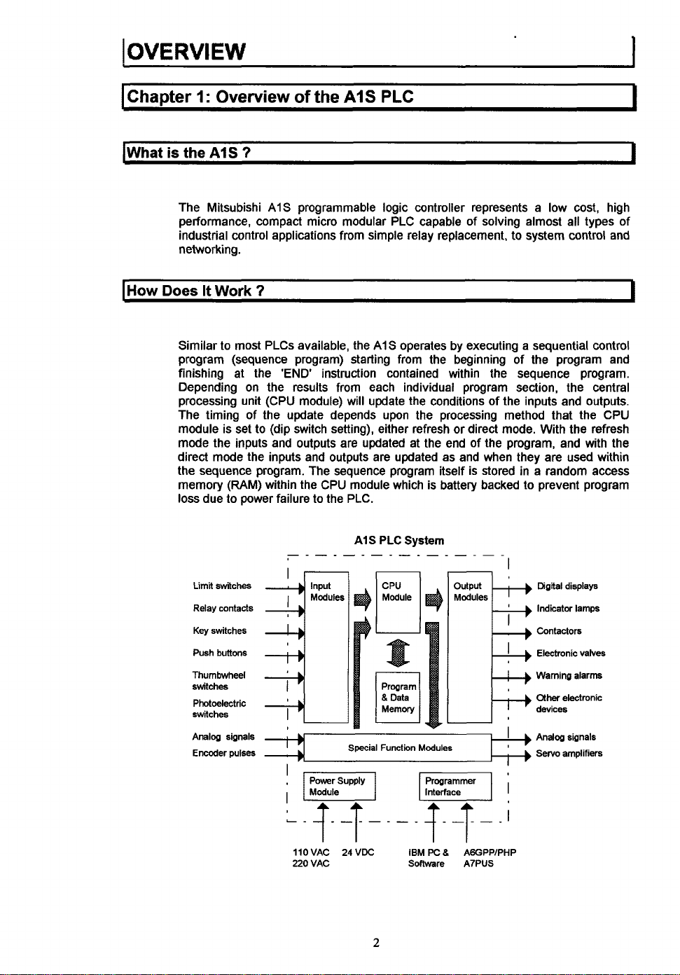
Similar
to
program (sequence program) starting from the beginning of the program and
finishing at the
Depending on the results from each individual program section, the central
processing unit (CPU module) will update the conditions of the inputs and outputs.
The timing of the update depends upon the processing method that the CPU
module is set to (dip switch setting), either refresh or direct mode. With the refresh
mode the inputs and outputs are updated at the end of the program, and with the
direct mode the inputs and outputs are updated as and when they are used within
the sequence program. The sequence program itself is stored in
memory (RAM) within the CPU module which is battery backed to prevent program
loss due to power failure to the PLC.
AIS
programmable logic controller represents a low cost, high
?
most PLCs available, the
'END
instruction contained within the sequence program.
A1S
to system control and
AIS
operates by executing a sequential control
a
random access
PLC
System
I
I
I
Limit
switches
Relay contacts
Key
switches
Push buttons
Thumbwheel
switches
Photoelectric
switches
Analog signals
Encoder
pulses
Input
~
I
,~l
I
L_
s
llOVAC 24VDC IBM
220 VAC Soflware
2
Modules
Programmer
F]i
!X
8
AGGPPIPHP
A7PUS
Digital displays
Indicator lamps
Contactors
Electronic valves
Warning alarm
other
electronic
devices
Servo
amplifiers
OVE
RVI
E
w
1
lWhat
(Where
Do
I
Choose
Understandably, when you look at the complete list of different types
output, and special function module available for the AIS, it can seem a difficult
task to choose what you require for your application. But don't worry, the reason for
all the different types of module is
application. All you have
input and output to be used in your application, and select the right type and
number of modules from the list. The only other things to consider then are that you
need a
modules you have selected. Also choose the programming device you want to use
for the creation of your sequence program.
&
How
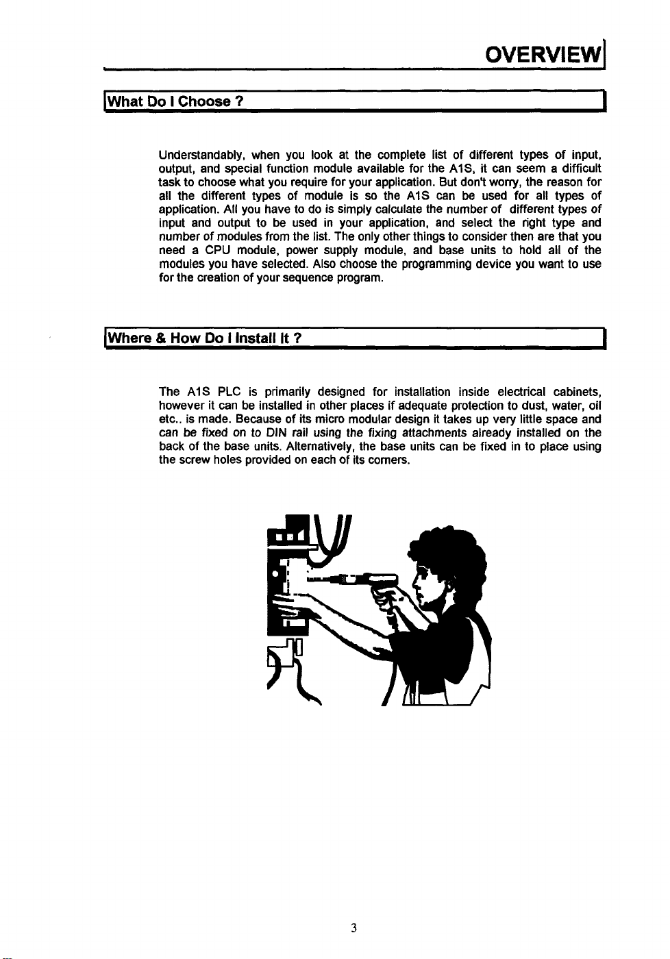
The AIS
however it can
etc.. is made. Because of its micro modular design it takes up very little space and
can be fixed
back of the base units. Alternatively, the base units can be fixed in to place using
the screw holes provided on each of its corners.
7
so
to do is simply calculate the number
CPU
module, power supply module, and base units to hold all of the
Do
I
Install It
PLC
is primarily designed for installation inside electrical cabinets,
be
on
to
7
installed in other places if adequate protection to dust, water, oil
DIN
rail using the fixing attachments already installed on the
the AIS can be used for all types of
of
different types of
of
input,
I
I
3
..
I
OVERVIEW
11s
It
Difficult
To
Program
7
..
.
....
..
. . . . .
....
.
...
.
-
1
I
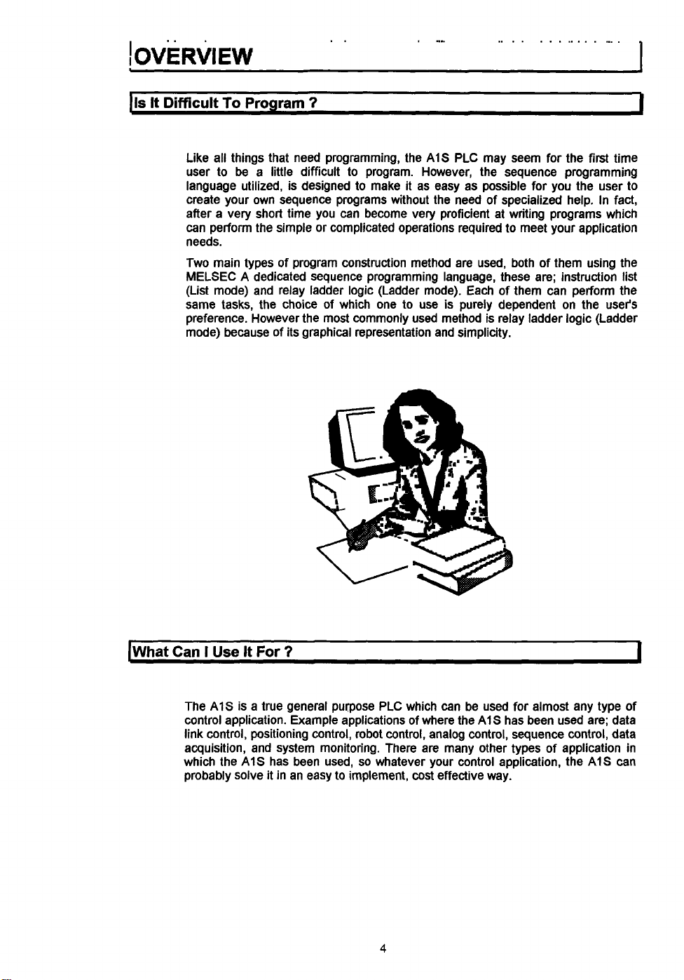
Like all things that need programming, the
user to be a little difficult to program. However, the sequence programming
language utilized, is designed to make it as easy as possible for you the user
create your own sequence programs without the need of specialized help. In fact,
after a very short time you can become very proficient at writing programs which
can perform the simple or complicated operations required
needs.
Two main types of program construction method are used, both
MELSEC
(List mode) and relay ladder logic (Ladder mode). Each of them can perform the
same tasks, the choice of which one to use is purely dependent on the user's
preference. However the most commonly used method is relay ladder logic (Ladder
mode) because of its graphical representation and simplicity.
A
dedicated sequence programming language, these are; instruction list
AIS
PLC may seem for the first time
to
meet your application
of them using the
to
[What
Can
I
Use
It
For
7
The
A1S
control application. Example applications of where the
link control, positioning control, robot control, analog control, sequence control, data
acquisition, and system monitoring. There are many other types
which the
probably solve it in an easy
is a true general purpose PLC which can be used for almost any type of
A1S
has been used,
so
whatever your control application, the
to
implement,
cost
4
A1S
effective way.
has been used are; data
of
application in
AIS
1
can
I
Chanter
2:
AIS
Module Descrintions
I
h
ICentral processing unit (CPU Module)
I
Model
No.
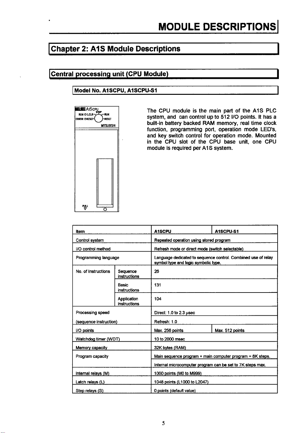
AISCPU. AISCPUSI
The CPU module is the main part of the
]ERROR
ORM
u-=
UlPjUBlsn
system, and can control up
built-in battery backed
function, programming port, operation mode
and key switch control for operation mode. Mounted
in the CPU slot of the CPU base unit, one CPU
module
r
is
required per
to
512
110
points.
RAM
memory, real time clock
AIS
system.
AIS
It
LEDs,
b
I
I
PLC
has a
Internal relays
Latch relays (L)
Step relays
(S)
(M)
Internal microcomputer
IO00
points
(MO
to
M999)
1048
points (LlO00 to L2047)
0
points
(default
value)
5
program
can
be
set
to
7K
steps
max.
1024 points (BO
256
points
to B3FF)
Specifidins
(W)
(R)
(M)
Number of
points
Specifmtions
2)
(1)
power failure
Counters (C)
Data reaisters (D)
Link registers
Annunciators (F)
File registers
Accumulator (A)
Index registers (V.
Pointers (P)
Interrupt pointers
Special relays
Special data registers (D)
Comments
Self dwnostic functions
Operation mode at time
STOP RUN output mode
Allowable
momentary
Current consumption
(5
VDC)
Weight
of
error
100
msec
$mer dng $me 0 1 to 3276 7
10
msec
timer
setting
time
0
01
100
msec
retentwe
timer
setting
to
to
(RO
131
range 1 to
D1023)
WlO23)
to
4095)
to
M9255)
to
D9255)
batches
setting
parameters)
256
pants
Normal
counter
Interrupt counter setting range 1
1024 points
1024 points
256
Max
2
2 points (V,
256
I
32 points
256
256 points
1
Max
Watchdog error, memory error detection, CPU error
I/O
1
STOP/CONTINUE
Output data
execution
20
04A
0
37 k9/0 81 Ib
(DO
(WO
pants (FO to F255)
4096
polnts
points (AO, AI)
Z)
points (PO to P255)
(IO
to
pants
(M9wo
(woo0
1600
points (set in
error detectmn, battery error detectmn, etc
at
time of STOP restoddata output after operation
msec
to
327 67
time 0 1
32767 (CO
to
32767
of
64
points)
sec
sec
to
(set
3276.7
to
(TO
to
1199)
(T200
to
sec
C255)
in
parameters)
detect~on,
T255)
(set in
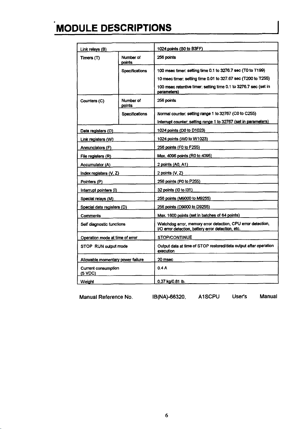
Manual Reference No. IB(NA)-66320.
6
A1
SCPU
User's
Manual
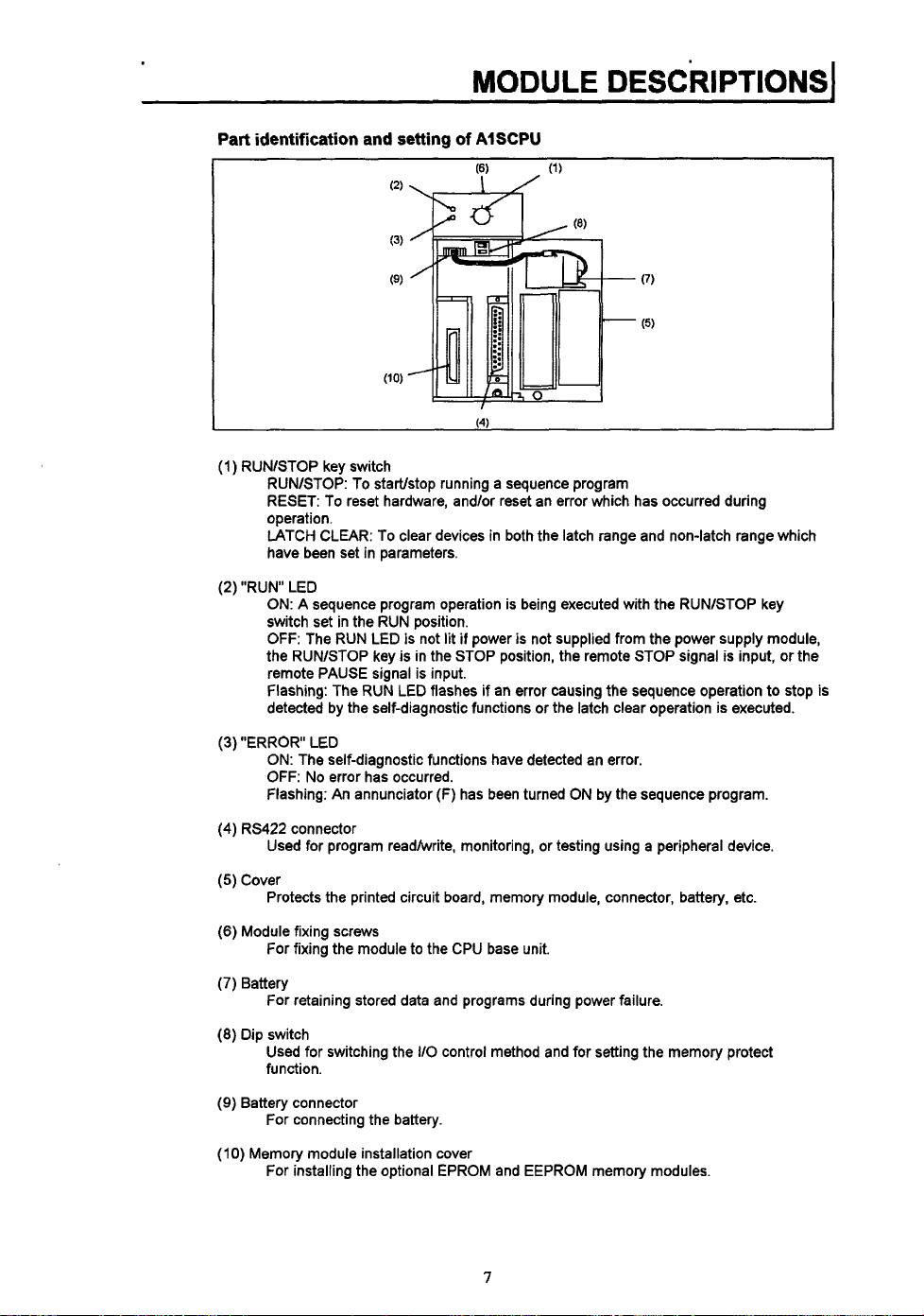
Part identification and setting
of
AISCPU
I
(1)
RUNlSTOP key switch
RUNASTOP: To startlstop running a sequence program
RESET: To reset hardware, and/or reset an error which has occurred during
operation.
LATCH CLEAR: To clear devices in both the latch range and non-latch range which
have been set in parameters.
(2) "RUN LED
ON:
A sequence program operation is being executed with the RUNlSTOP key
switch set in the RUN position.
OFF:
The RUN LED is not lit
the RUNlSTOP key
is
remote PAUSE signal is input.
flashing: The RUN LED flashes if an error causing the sequence operation to stop is
detected by the self-diagnostic functions or the latch clear operation is executed.
if
power
is
not supplied from the power supply module,
in the STOP position, the remote STOP signal is input, or the
(3)
"ERROR LED
ON: The self-diagnostic functions have detected an error.
OFF:
No error has occurred.
Flashing: An annunciator
(4)
RS422 connector
(F)
has been turned ON by the sequence program.
Used for program readhvrite, monitoring, or testing using a peripheral device.
(5)
Cover
Protects the printed circuit board, memory module, connector, battery, etc.
(6)
Module fixing screws
For fixing the module to the CPU base unit.
(7)
Battery
For retaining stored data and programs during power failure.
(8)
Dip switch
Used for switching the
IlO
control method and for setting the memory protect
function.
(9)
Battery connector
For connecting the battery.
(IO)
Memory module installation cover
For installing the optional EPROM and EEPROM memory modules.
7
kPU
Base
Units
I
The CPU base units are for mounting the CPU module, 1 power supply module,
and a number of
to the CPU base unit is dependent
the CPU module, each system requires one CPU base unit. Below is a list of the
different CPU base unit models;
I
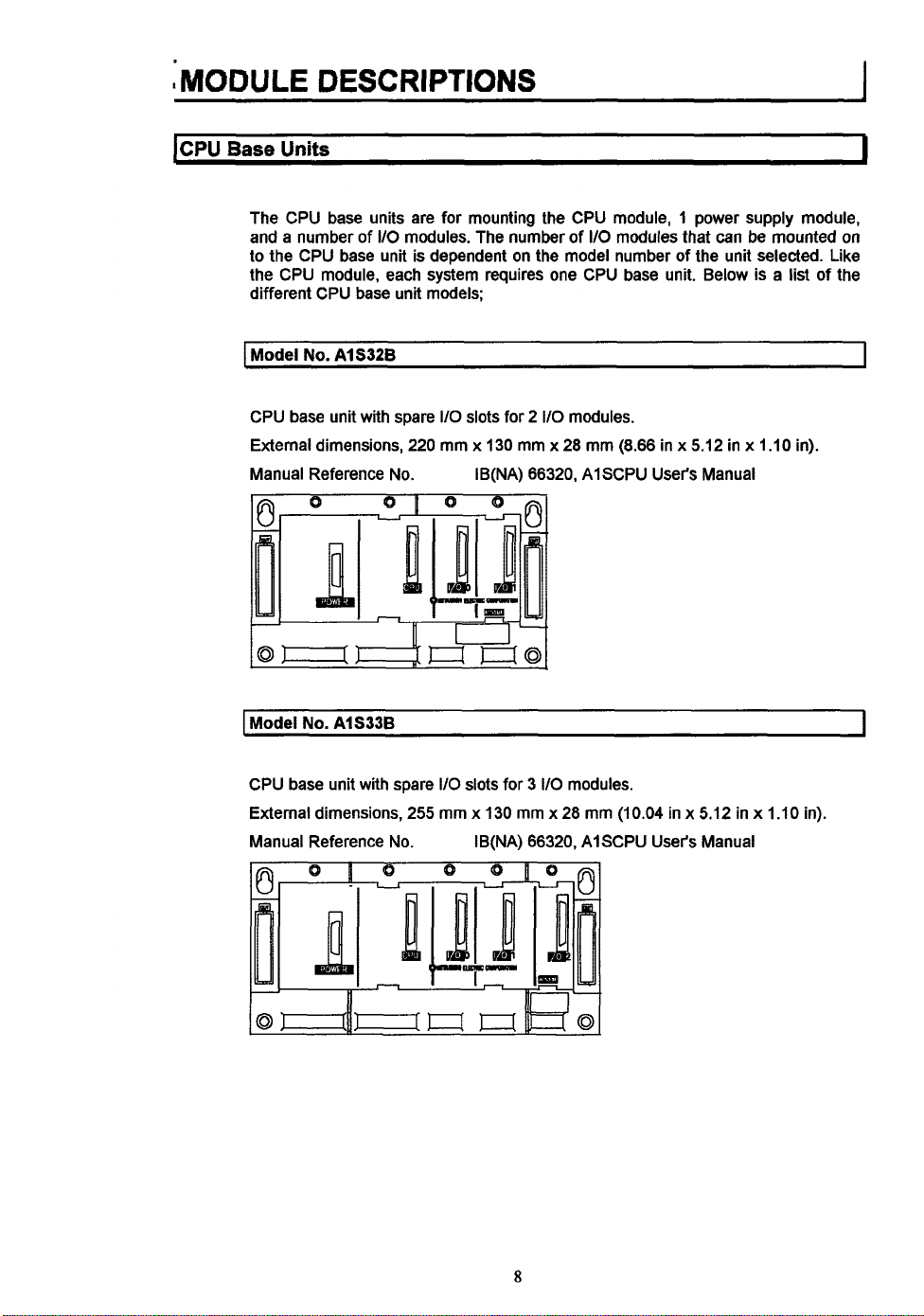
Model
No.
CPU base unit with spare
External dimensions,
Manual Reference No. IB(NA) 66320, AlSCPU User's Manual
1Model
No.
110
AI 5326
AlS33B
modules. The number
I/O
slots for 2
220
mm x 130 mm x 28 mm (8.66 in x 5.12 in x 1.10
of
I/O
on
the model number
110
modules.
modules that can be mounted
of
the unit selected. Like
in).
on
I
I
CPU base unit with spare 110 slots for
External dimensions, 255 mm
Manual Reference No. IB(NA) 66320, AlSCPU
3
I/O
modules.
x
130 mm x 28 mm (10.04 in x 5.12 in x 1.10 in).
8
User's
Manual
I
Model
No.
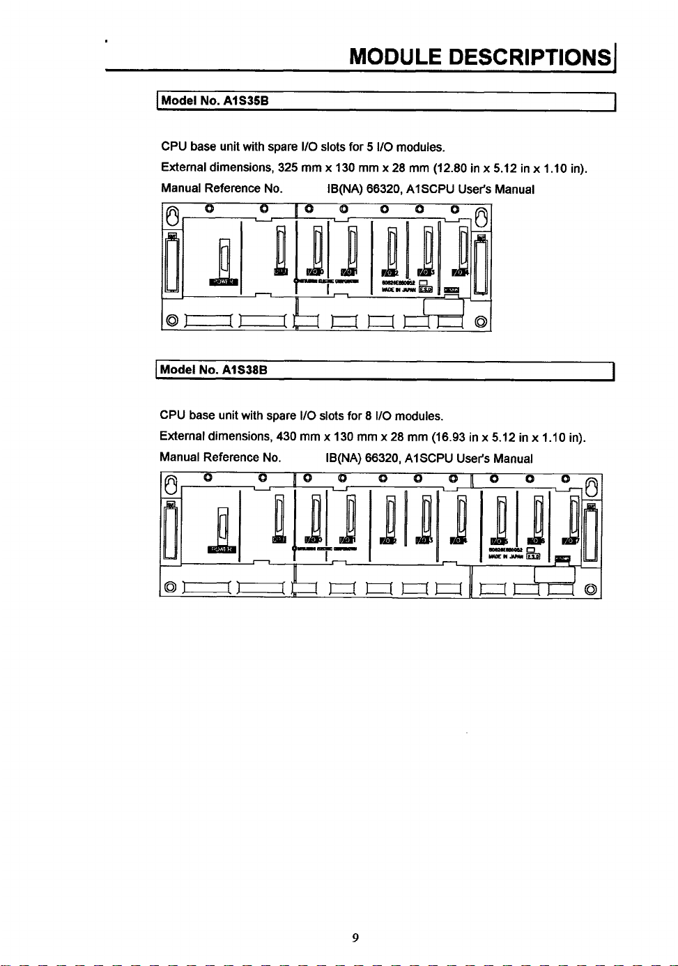
AlS35B
MODULE DESCRIPTIONS
I
I
CPU base unit with spare
External dimensions, 325
Manual Reference No. IB(NA) 66320, AISCPU User's Manual
I
Model
No.
AlS38B
CPU base unit with spare
External dimensions, 430
Manual Reference No.
110
slots
for
5
I/O
modules.
mm
x
130
mm x 28
110
slots for 8
mm
x
130
mm
IB(NA) 66320, AISCPU User's Manual
I10
modules.
x
28
mm
(12.80 in x 5.12 in x 1.10 in).
mm
(16.93 in x 5.12 in
x
1.10
I
in).
9
MODULE
I
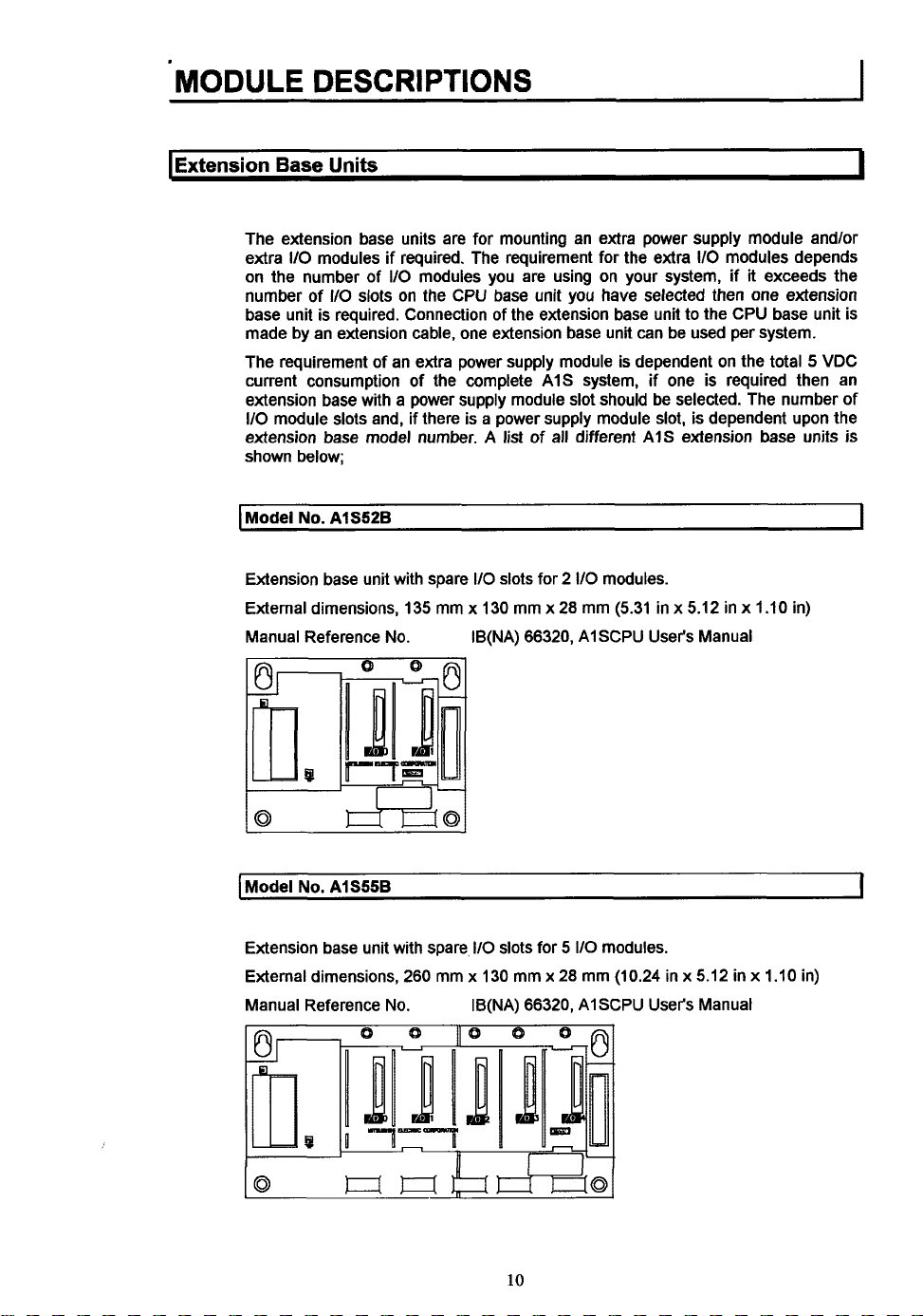
Extension Base
The extension base units are for mounting an extra power supply module andlor
extra
110
on the number of
number of
base unit is required. Connection of the extension base unit to the CPU base unit is
made by an extension cable, one extension base unit can be used per system.
The requirement of an extra power supply module is dependent on the total 5 VDC
current consumption of the complete A1S system, if one
extension base with a power supply module slot should be selected. The number of
110
module slots and, if there is a power supply module slot, is dependent upon the
extension base model number. A list of all different AIS extension base units
shown below;
I
Model
No.
DESCRIPTIONS
Units
modules if required. The requirement for the extra 110 modules depends
110
AlS52B
110
slots on the CPU base unit you have selected then
modules you are using on your system, if it exceeds the
is
required then an
one
extension
I
is
I
Extension base unit with spare
External dimensions, 135 mm x 130 mm x 28 mm (5.31 in x 5.12 in x 1.10 in)
Manual Reference No. IB(NA) 66320, AISCPU User's Manual
I
Model
No.
AlS55B
Extension base unit with spare, 110 slots for
External dimensions, 260 mm
Manual Reference
No.
110
slots for 2
x
130 mm
IB(NA) 66320,
x
110
modules.
5
110
modules.
28
mm (10.24 in x 5.12 in x 1.10 in)
AI
SCPU User's Manual
I
10

I
Model
No.
A15588
MODULE
DESCRIPTIONS1
I
Extension base unit with spare
External dimensions, 365 mm
Manual Reference No. IB(NA) 66320, AISCPU User's Manual
I
Model
No.
AlS65B
Extension base unit with spare
module slot.
External dimensions, 315 mm x 130 mm x 28 mm (12.40 in x 5.12 in x I
Manual Reference No.
I/O
slots for 8 110
x
130 mm x 28 mm (14.37 in x 5.12 in
110
slots for
IB(NA) 66320, AISCPU
modules.
5
I10
modules and a power supply
User's
Manual
x
1.10
.10 in)
in)
1
I
Model
No.
AlS68B
Extension base unit with spare
module slot.
External dimensions, 420 mm
Manual Reference
No.
110
slots
for 5 110
x
130 mm x 28 mm (16.54 in x 5.12 in x 1.10 in)
IB(NA) 66320, AISCPU
11
modules and a power supply
User's
Manual
I
1
I
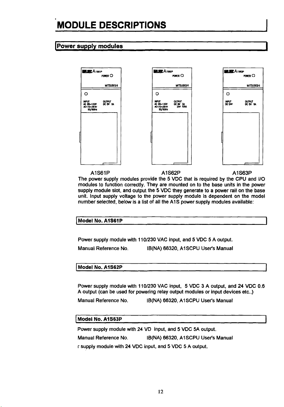
AIS61P
The power supply modules provide the 5 VDC that is required by the CPU and
modules to function correctly. They are mounted on to the base units in the power
supply module slot, and output the
unit. Input supply voltage to the power supply module is dependent on the model
number selected, below is
I
Model
No.
AISGIP
Power supply module with 110/230 VAC input, and 5 VDC 5 A output.
Manual Reference
I
Model
No.
AlS62P
No.
a
list of all the A1 S power supply modules available:
AlS62P AlS63P
5
VDC they generate to a power rail on the base
IB(NA) 66320, AISCPU User's Manual
I/O
1
I
Power supply module with 11Of230 VAC input, 5 VDC 3 A output, and 24 VDC 0.6
A output
Manual Reference No. IB(NA) 66320, AlSCPU User's Manual
I
Model
Power supply module with 24 VD input, and 5 VDC SA output.
Manual Reference No.
r supply module with 24 VDC input, and
(can
be used for powering relay output modules or input devices etc..)
No.
AlS63P
~~ ~
IB(NA) 66320, AISCPU User's Manual
5
VDC 5 A output.
12
I
.. ..
MODULE
DESCRIPTIONS1
t
"'I
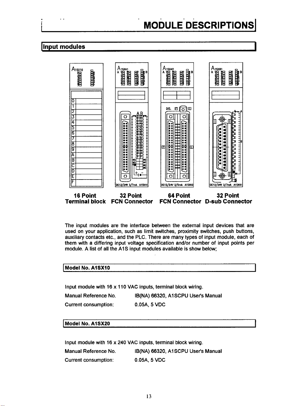
Terminal block
The input modules are the interface between the external input devices that are
used on your application, such as limit switches, proximity switches, push buttons,
auxiliary contacts etc., and the PLC. There are many types of input module, each of
them with a differing input voltage specification and/or number of input points per
module. A
16
I
Point
list
of all the AIS input modules available
32
Point
FCN Connector
64
Point
FCN Connector
is
show below;
D-sub
Connector
Model
No.
AISXIO
Input module with 16 x 110 VAC inputs, terminal block wiring.
Manual Reference No.
Current consumption: 0.05A,
I
Model
No.
AISXZO
Input module with 16 x
Manual Reference No.
Current consumption: 0.05A,
IB(NA)
66320,
AISCPU User's Manual
5
VDC
240
VAC inputs, terminal block wiring.
66320,
IB(NA)
13
AI SCPU User's Manual
5
VDC
I
I
*
. .
. . .
..
MODULE
I
Model
Input module with 16 x 24 VAC or 24 VDC inputs, terminal block wiring.
Manual Reference No.
Current consumption: O.O5A,
I
Model
Input module with 16 x 12 or 24 VDC inputs (sink type), terminal block wiring.
Manual Reference No.
Current consumption: 0.05A,
I
Model
Input module with 16 x 24 VDC high speed inputs (sink type), terminal block wiring.
Manual Reference No.
Current consumption: O.O5A,
..
DESCRIPTIONS
No.
AlSXSO
IB(NA) 66320, A1 SCPU User's Manual
No.
AlSX40
IB(NA) 66320, AISCPU User's Manual
No.
AlSX40-W
IB(NA) 66320, AlSCPU User's Manual
5
5
5
VDC
VDC
VDC
..
..
. ...
.
I
I
I
I
Model
No.
AlSX4052
Input module with 16 x 24 VDC inputs (sink type), terminal block wiring.
Manual Reference No.
Current consumption: 0.05A.
I
Model
No.
AlSX41
Input module with 32 x 12 or 24 VDC inputs (sink type), FCN connector wiring.
Manual Reference No.
Current consumption: 0.08A,
Model
No.
AlSX4lS2
Input module with 32 x 24 VDC inputs (sink type), FCN connector wiring.
Manual Reference No.
Current consumption: O.O8A,
IB(NA) 66320, AlSCPU User's Manual
5
VDC
IB(NA) 66320, A1 SCPU User's Manual
5
VDC
IB(NA) 66320, AlSCPU User's Manual
5
VDC
I
I
I
14
MODULE DESCRIPTIONS~
I
Model
No.
AlSX42
Input module with 64 x 12 or 24 VDC inputs (sink type), FCN connector wiring.
Manual Reference No.
Current consumption: 0.09A,
1
Model
No.
AI SX42S2
Input module with 64 x 24 VDC inputs (sink type), FCN connector wiring.
Manual Reference No.
Current consumption: O.O9A,
I
Model
No.
AlSX71
IB(NA) 66320, AISCPU User's Manual
5
VDC
IB(NA) 66320, AlSCPU User's Manual
5
VDC
I
I
I
Input module with 32 x 5
wiring.
Manual Reference No.
Current consumption: O.O75A,
I
Model
No.
AlSX8O
Input module with 16 x 12 or 24 VDC inputs (sink or source type), terminal block
wiring.
Manual Reference No.
Current consumption: O.O5A,
1
Model
No.
AlSX80-W
Input module with 16 x 24 VDC high speed inputs (sink or source type), terminal
block wiring.
Manual Reference No.
Current consumption: 0.05A, 5 VDC
I
Model
N3.
AISX80S2
or 12 VDC inputs (sink or source type), FCN connector
IB(NA) 66320, AISCPU User's Manual
5
VDC
IB(NA) 66320, AISCPU User's Manual
5
VDC
User's
IB(NA) 66320, AISCPU
Manual
i
I
I
Input module with 16 x 24 VDC inputs (sink or source type), terminal block wiring.
Manual Reference No.
Current consumption: 0.05A,
IB(NA) 66320, AISCPU User's Manual
5
VDC
15
MODULE
I
Model
DESCRIPTIONS
No.
AlSX81
I
Input module with 32 x 12
wiring.
Manual Reference
Current consumption: 0.08A, 5 VDC
I
Model
No.
Input module with 32 x 24 VDC inputs (sink
Manual Reference
Current consumption: 0.05A, 5 VDC
No.
AlSX81S2
No.
or
24 VDC inputs (sink
IB(NA) 66320, AI SCPU User's Manual
IB(NA) 66320, AISCPU User's Manual
or
source type), D-sub connector
~
or
source type), D-sub connector wiring.
I
16
MODULE
DESCRIPTIONS1
I
loutnut
modules
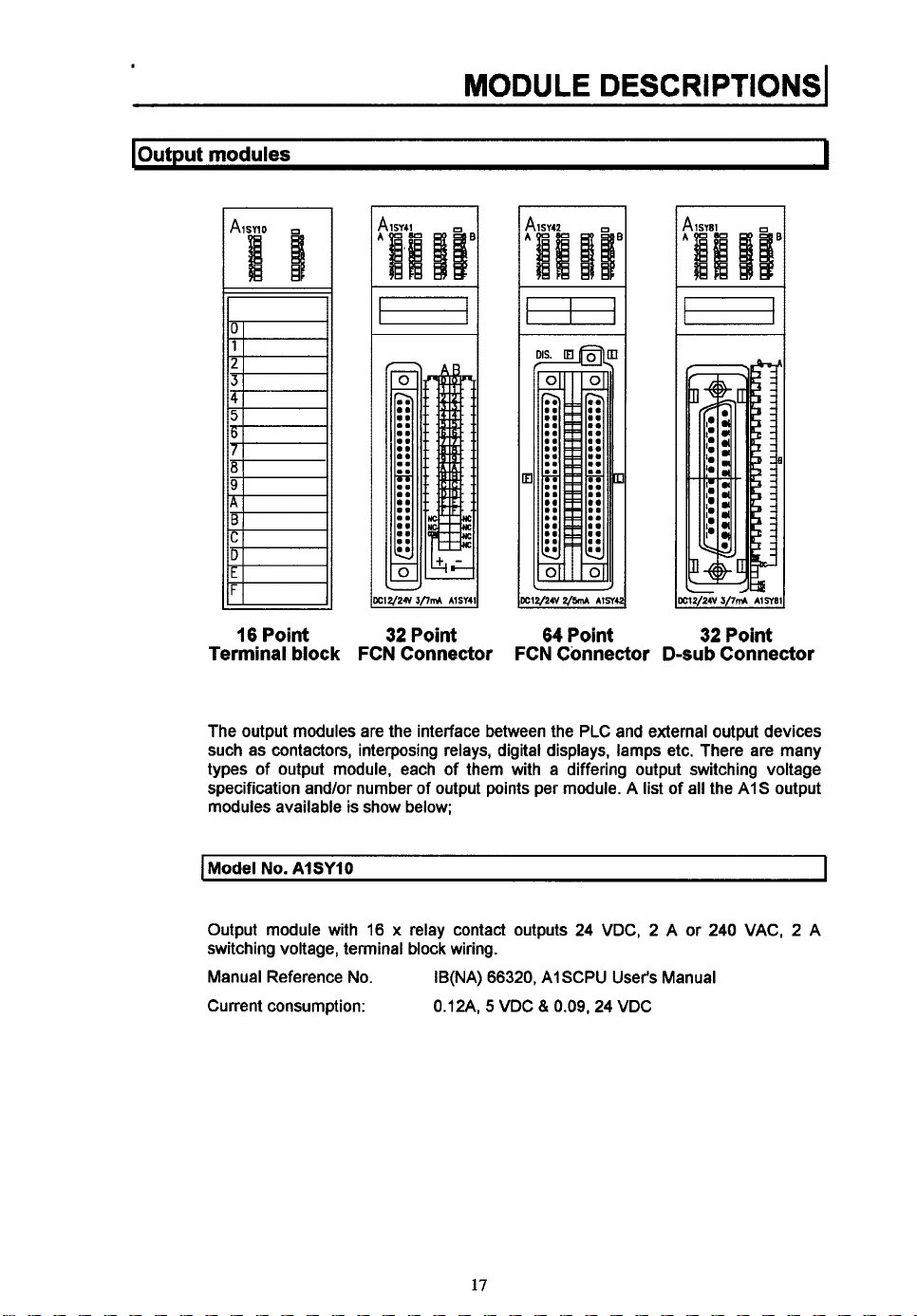
16
Point
Terminal
block
32
Point
FCN Connector
3
c12/24v2/m
FCN Connector D-subConnector
64
r1ne
Point
32/21
32
3/7&
Point
AlSY8l
I
The output modules are the interface between the PLC and external output devices
such as contactors, interposing relays, digital displays, lamps etc. There are many
types of output module, each of them with a differing output switching voltage
specification and/or number of output points per module. A list
modules available is show below;
I
Model
No.
AlSYlO
Output module with
switching voltage, terminal block wiring.
Manual Reference No.
Current consumption:
16 x relay contact outputs
IB(NA)
66320,
AISCPU User's Manual
5
WDC
81
0.12A,
0.09,24
24
WDC, 2 A or
WDC
of
all the AIS output
240
WAC, 2 A
I
17
I
Model
No.
AlSY18A
Output module with 8 x independent relay contact outputs 24 VDC, 2 A or 240 VAC,
2 A switching voltage, terminal block wiring.
Manual Reference No.
Current consumption:
Model
No.
AlSY22
Output module with 16 x triaciSSR outputs 100-240 VAC, 0.6 A switching voltage,
terminal block wiring.
Manual Reference No.
Current consumption:
I
Model
No.
AlSY28A
Output module with 8 x independent triadSSR outputs 100-240 VAC, 1 A switching
voltage, terminal block wiring.
Manual Reference No.
Current consumption:
IB(NA) 66320, A1 SCPU User's Manual
&
0.24A, 5 VDC
IB(NA) 66320, AlSCPU User's Manual
0.27A, 5 VDC
IB(NA) 66320, AI SCPU User's Manual
0.1 lA, 5 VDC
O.O75A, 24 VDC
&
O.O04A, 200 VAC
I
I
I
[Model
I
No.
AlSY40
Output module
switching voltage, terminal block wiring.
Manual Reference No.
Current consumption:
Model
No.
Output module with 32 x transistor outputs (sink type) 12 or 24 VDC, 0.1 A
switching voltage, FCN connector wiring.
Manual Reference
Current consumption:
with
AlSY41
16 x transistor outputs (sink type) 12
IB(NA) 66320, AlSCPU User's Manual
No.
0.27A, 5
IB(NA) 66320, AlSCPU User's Manual
0.50A, 5 VDC
18
VDC
& 0.016A. 24 VDC
&
O.O16A, 24 VDC
or
24 VDC, 0.1 A
I
I
I
Model
No.
AlSY42
I
Output module with
switching voltage, FCN connector wiring.
Manual Reference No.
Current consumption:
I
Model
No.
AlSY50
Output module with 16 x transistor outputs (sink type) 12 or 24 VDC,
switching voltage, terminal block wiring.
Manual Reference No.
Current consumption:
I
Model
No.
AISYGO
Output module with
voltage, terminal block wiring.
Manual Reference No.
Current consumption:
I
Model
No.
AISYGOE
64
x
transistor outputs (sink type) 12 or 24 VDC, 0.1
IB(NA) 66320, AISCPU User's Manual
5
0.93A,
IB(NA) 66320, AISCPU User's Manual
0.12A,
~
16
x
transistor outputs (sink type) 24 VDC, 2 A switching
IB(NA) 66320, AISCPU User's Manual
0.12A,
VDC 8 0.016A, 24 VDC
5
VDC & 0.12A, 24 VDC
5
VDC &
O.O15A,
24 VDC
0.5
A
I
A
I
I
Output module with 16 x transistor outputs (source type) 5 or 12 or 24 VDC, 1 A
switching voltage, terminal block wiring.
Manual Reference No.
Current consumption:
I
Model
No.
AlSY68A
Output module with 8 x independent transistor outputs (sink or source type) 5 or 12
or 24 or 48 VDC, 2 A switching voltage, terminal block wiring.
Manual Reference No.
Current consumption: 0.13A,
IB(NA) 66320, AISCPU User's Manual
5
0.20A,
IB(NA) 66320, AISCPU User's Manual
VDC & 0.01A, 24 VDC
5
WDC
19
I
MODULE
I
Model
No.
Output module with 32 x transistor outputs (sink type) 5 or 12 VDC, 16 mA
switching voltage, FCN connector wiring.
Manual Reference No.
Current consumption:
I
Model
No.
DESCRIPTIONS
AISY71
IB(NA) 66320, AI SCPU User's Manual
5
0.40A,
AISYIO
I
VDC & O.I5A, 24 VDC
I
Output module with 16 x transistor outputs (source type) 12 or 24 VDC,
switching voltage, terminal block wiring.
Manual Reference No.
Current consumption:
I
Model
No.
AISYII
Output module with 32 x transistor outputs (source type) 12 or 24 VDC,
switching voltage, D-sub connector wiring.
Manual Reference
Current consumption:
No.
IB(NA) 66320, AISCPU User's Manual
5
0.12A,
IB(NA) 66320, AISCPU User's Manual
0.50A,
VDC & O.O4A, 24 VDC
5
VDC & O.O16A, 24 VDC
-
0.8
0.1
A
-1
A
20
!.
I
..
MODULE
DESCRIPTIONSI
ISpecial
function
a
A1 S62DA
Analog
modules
Output
A1 SD61
High Speed
Counter
A1 SJ71 T21
MELSECNET/B
B
I
AlSJTl C24-R2
Computer Link
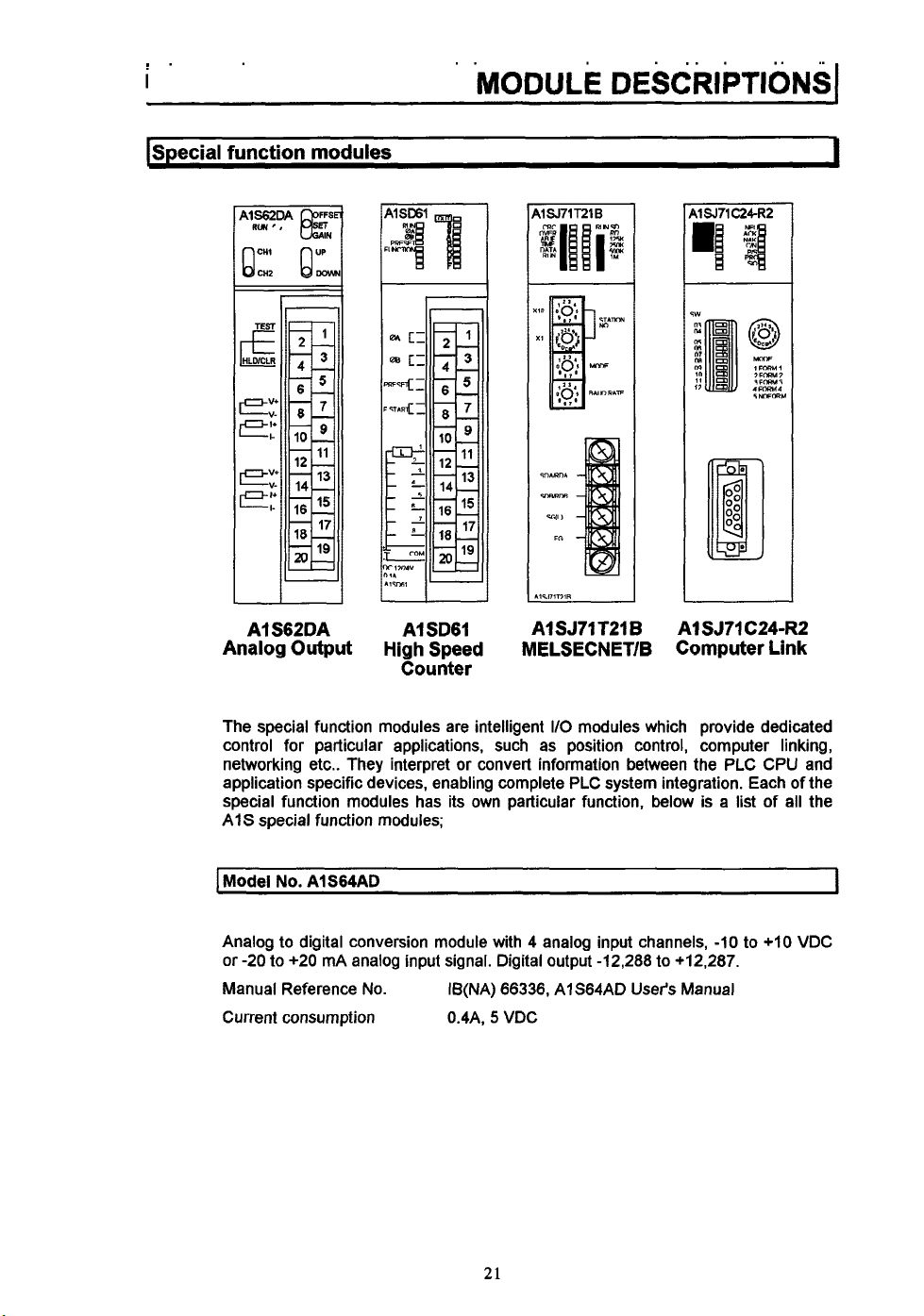
The special function modules are intelligent
control for particular applications, such as position control, computer linking,
networking etc.. They interpret or convert information between the PLC CPU and
application specific devices, enabling complete PLC system integration. Each of the
special function modules has its own particular function, below is a list of all the
AIS special function modules;
I
Model No.
Analog to digital conversion module with 4 analog input channels,
or
-20 to +20 mA analog input signal. Digital output -12,288 to +12,287.
Manual Reference
Current consumption 0.4A,
AlS64AD
No.
IB(NA) 66336, AlS64AD User's Manual
5
21
VDC
I/O
modules which provide dedicated
-10
to +IO VDC
I
MODULE
I
Model
No.
Digital to analog conversion module with 2 analog output channels, -1 0 to +10 VDC
0
to +20 mA analog output signal. Digital input -12,000 to +12,000.
or
Manual Reference No.
Current consumption OBA,
I
Model
No.
RS232C computer link module with 1 RS232C communication port. Full or half
duplex transmission, 4 protocol modes, no-protocol mode, bi-directional mode, and
protocol switching function.
Manual Reference No.
Current consumption
I
Model
No.
RS422/485 computer link module with 1 RS42Z485 communication port. Full or
half duplex transmission, 4 protocol modes, no-protocol mode, bi-directional mode,
protocol switching function, and multidrop capability.
Manual Reference No.
Current consumption O.lA,
DESCRIPTIONS
AlS62DA
IB(NA) 66335, AlS62DA User's Manual
5
VDC
AlSJllC24-RZ
IB(NA) 66270, A1 SJ71 C24-RZPRF User's Manual
O.IA,
5
VDC
AlSJ71C24R4
IB(NA) 66364, AlSJ7lC24-R4 User's Manual
5
VDC
I
I
I
I
I
Model
No.
AISJ71C24-PRF
RS232C printer module with 1 RS232C communication port. Full or half duplex
transmission, 31 variable and 400 fixed message storage, with messages up to
characters long.
Manual Reference No.
Current consumption
IB(NA) 66270, A1 SJ71 C24-R2/PRF User's Manual
O.lA,
5 VDC
22
I
80
I
Model
No.
AISD61
MODULE
DESCRIPTIONS~
I
High speed counter module with 1 single or bi-phase input channel. Maximum
count speed
outputs, ring counter function, limit switch function, hold function, and sampling
function.
Manual Reference No.
Current consumption 0.35A,
I
Model
High
speed
points. Minimum input pulse length
Manual Reference No.
Current consumption 0.057A,
I
Model
MELSECNET/B data link system interface module. Connects on
network linking up to 32
speed up to
Manual Reference No.
Current consumption 0.66A,
50
KHz, 32 bit signed binary count range, 8 comparison transistor
IB(NA) 66337, AISD61 User's Manual
5
VDC
No.
AIS161
interrupt module with 16 x 12 or 24 VDC high speed interrupt input
0.5
ms, rising edge or falling edge interrupts.
IB(NA) 66396, AIS161 User's Manual
5
VDC
No.
AlSJ71 T21
1
Mbaud, and
B
AIS
PLCs, twisted pair cable connection, transmission
1
K byte link points per station.
IB(NA) 66339, AI SJ71 T21 B User's Manual
5
VDC
to
MELSECNET/B
I
I
I
Model
No.
AlSJ71PT32-W
MELSECNET/MINI-S3 remote
remote I/O points, twisted pair or plastic fiber optic connection, transmission speed
1.5 Mbaud, allows connection of
series inverters.
Manual Reference No.
Current consumption 0.0.35A,
I/O
network master module. Controls up to
F
and
FX
series PLCs, A2C
IB(NA) 66368, A1 SJ71 PT32-S3 User's Manual
5
VDC
23
I/O
modules, and
512
I
Z
MODULE
I
Model
Single axis positioning module with one analog output channel. 32 bit signed binary
positioning range, 1 to 400,000 PLSlSec positioning speed, zeroing and jogging
functions.
Manual Reference No. IB(NA) 66367, AlSD70 User's Manual
Current consumption 0.3A,
I
Model
DESCRIPTIONS
No.
AISD7O
No.
AlSD71S2
5
VDC
8
024,
+15 VDC & 0.02A
1
-1 5 VDC
I
Two axis positioning module with
16,252,928. 10 to 200,000 PLSlSec positioning speed, zeroing, M-code, backlash,
compensation, and jogging functions.
Manual Reference No.
Current consumption
Model
No.
AISPGO
Pulse catch module with 16 x 24 VDC pulse input points. Pulse catch or normal
input function, minimum pulse width
Manual Reference No.
Current consumption 0.055A,
I
Model
No.
AlSH42
Combined input and output module with 32 x 12 or 24 VDC input points, and 32 x
transistor outputs (sink type) 12 or 24 VDC switching voltage. Inputs and outputs
FCN connector wiring.
Manual Reference No.
Current consumption
two
pulse output channels. Positioning range 1 to
IB(NA) 66399, AlSD7142 User's Manual
0.8A,
5
VDC &0.05A, 4.75 to 26.4 VDC
0.5
ms.
IB(NA) 66398, AlSP6O User's Manual
5
VDC
IB(NA) 66320, AlSCPU User's Manual
5
VDC & 0.008,24 VDC
0.5A,
I
I
I
Model
No.
AlS42X
Dynamic input module with 16 x 12 or 24 VDC input points. Input points can be
automatically multiplexed for 16 or 32 or 48 or 64 points by switch selection.
Manual Reference No.
Current consumption 0.08A,
IB(NA) 66320, AlSCPU User's Manual
5
VDC
24
I
 Loading...