

Mitsubishi A1S64AD User Manual
A/D Converter module
t
y
pe A1S64AD
User's Manual
(Hardware)
Thank you for buying the Mitsubishi general-purpose programmable
logic controller MELSEC-A Series
Prior to use, please read both this manual and detailed manual
thoroughly and familiarize yourself with the product.
MODEL A1S64AD(H/W)-U-E
MODEL
CODE
13JE46
IB(NA)-66485-D(0609)MEE
©1994 MITSUBISHI ELECTRIC CORPORATION
DANGER
CAUTION
z SAFETY PRECAUTIONS z
(Read these precautions before using.)
When using Mitsubishi equipment, thoroughly read this manual and the
associated manuals introduced in this manual. Also pay careful attention to
safety and handle the module properly.
These precautions apply only to Mitsubishi equipment. Refer to the CPU
module user's manual for a description of the PLC system safety precautions.
These zSAFETY PRECAUTIONSz classify the safety precautions into two
categories: "DANGER" and "CAUTION".
Procedures which may lead to a dangerous condition
and cause death or serious injury if not carried out
properly.
Procedures which may lead to a dangerous condition
and cause superficial to medium injury, or physical
damage only, if not carried out properly.
Depending on circumstances, procedures indicated by
CAUTION may also
be linked to serious results.
In any case, it is important to follow the directions for usage.
Store this manual in a safe place so that you can take it out and read it
whenever necessary. Always forward it to the end user.
[PRECAUTIONS FOR DESIGN]
CAUTION
z Do not bunch the control wires or communication cables with the main
circuit or power wires, or install them close to each other.
They should be installed 100mm (3.9inch) or more from each other.
Not doing so could result in noise that may cause malfunction.
[INSTALLATION PRECAUTIONS]
CAUTION
z Use the PC in an environment that meets the general specificaitons
contained in this manual. Using this PC in an environment outside the
range of the general specifications could result in electric shock, fire,
erroneous operation, and damage to or deterioration of the product.
z Install so that the pegs on the bottom of the module fit securely into the
base unit peg holes.
The module fixing screws must be tighten by the specified torque.
Not installing the module correctly or tightening the screws to the terminal
base could result in erroneous operation, damage, or pieces of the product
falling.
[WIRING PRECAUTIONS]
CAUTION
z If there are high levels of noise, ground the AG terminal and FG terminal with
Class D grounding (Class 3 grounding) or higher dedicated for the PLC.
Failure to observe this could lead to malfunctioning.
z When wiring in the PLC, be sure that it is done correctly by checking the product's
rated voltage and the terminal layout. Connecting a power supply that is different
from the rating or incorrectly wiring the product could result in fire or damage.
z Tighten terminal screws to the specified torque.
If a terminal screw is not tightened to the specified torque, it the module may fall
out, short circuit, or malfunction.
If a terminal screw is tightened excessively, exceeding the specified torque, the
module may fall out, short circuit, or malfunction due to breakage of the screw or
the module.
z Be careful not to let foreign matters such as sawdust or wire chips get inside the
module. These may cause fires, failure or malfunction.
[STARTUP/MAINTENANCE PRECAUTIONS]
DANGER
z When power is on, do not touch the terminals.
Doing so can cause an electric shock or malfunction.
z Before starting cleaning or terminal screw retightening, always switch off the
power externally in all phases.
Not switching the power off in all phases can cause a module failure or
malfunction.
CAUTION
z Never disassemble or modify the module.
Failure to observe this could lead to trouble, malfunctioning, injuries or fires.
z Always turn the power OFF before installing or removing the module. Failure to
observe this could lead to module faults or malfunctioning.
z Do not install/remove the terminal block more than 50 times after the first use of
the product. (IEC 61131-2 compliant)
[PRECAUTIONS FOR DISPOSAL]
CAUTION
z Dispose of this product as industrial waste.
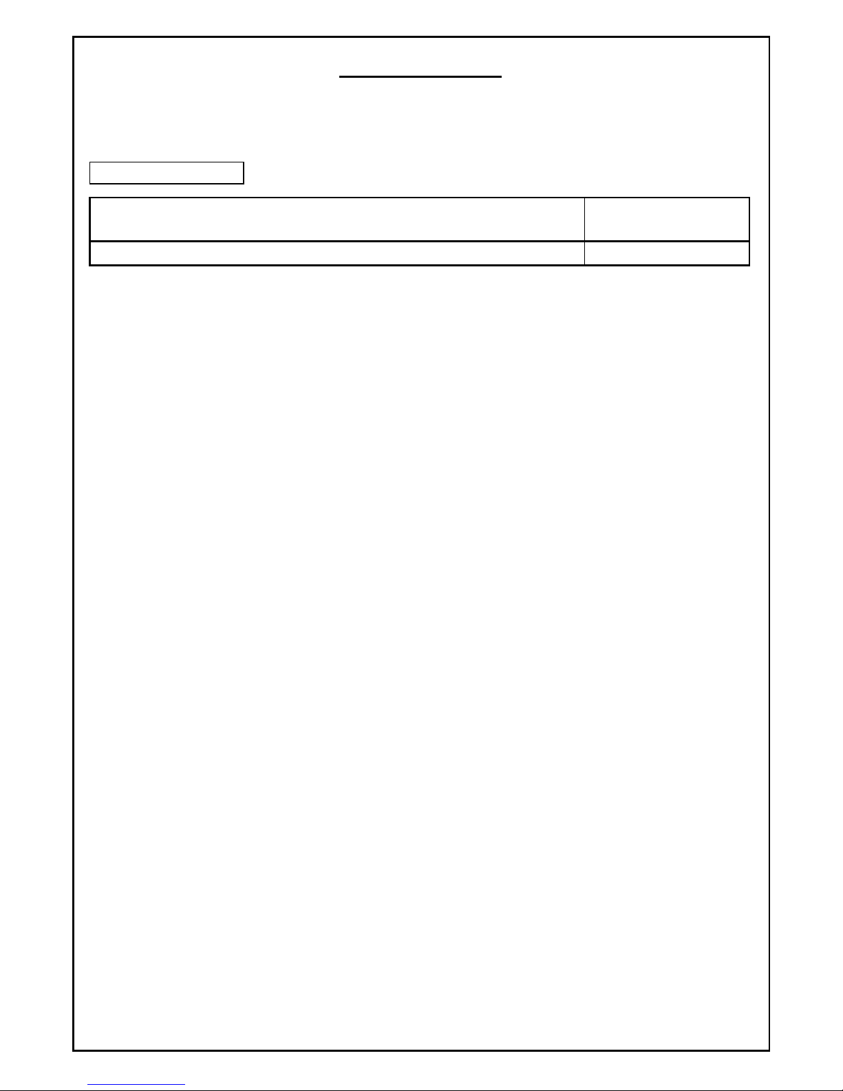
About the Manuals
The following manuals are related to this product.
Refer to the following table, and procure these manuals as necessary.
Detailed Manual
Manual name
Manual No.
(Model code)
A/D converter module type A1S64AD User’s Manual
IB-66336
1. Outline
This manual explains the specifications and names of each part of the A1S64AD type
analog/digital converter (hereinafter, A1S64AD) used in combination with the
MELSEC-A Series PLC CPU module (hereinafter PLC CPU).
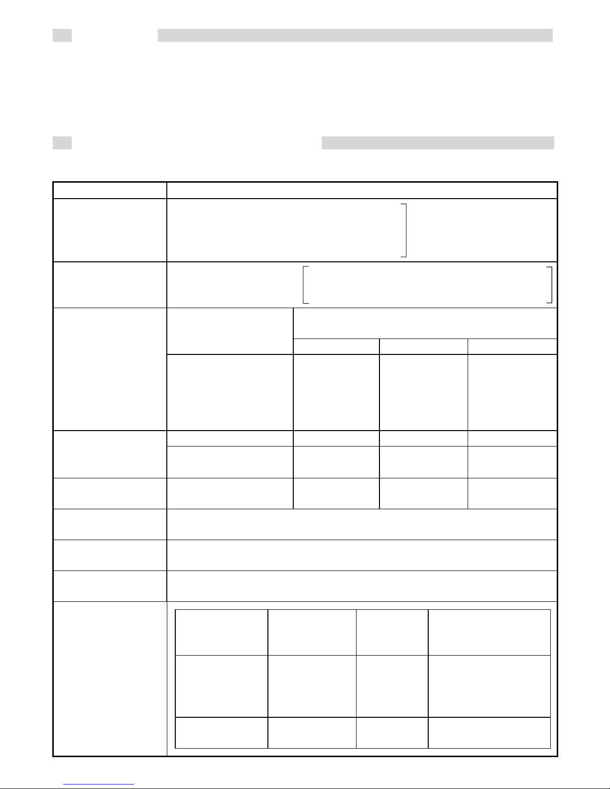
2. Performance Specifications
The performance specifications of the A1S64AD are shown below.
Item Specifications
Analog input
Voltage: -10 to 0 to +10VDC
(input resistance 1MΩ)
Current: -20 to 0 to +20mA
(input resistance 250Ω)
Select with the input
terminals.
Digital input 16-bit coded binary
-4096 to +4095 when set to 1/4000
-8192 to +8191 when set to 1/8000
-12288 to +12287 when set to 1/12000
Digital output value
(At 5V/20mA gain, 0V/90mA offset)
Analog input
1/4000 1/8000 1/12000
Input/output
characteristics *1
+10V
+5V or +20mA
0V or 0mA
-5V or -20mA
-10V
+4000
+2000
0
-2000
-4000
+8000
+4000
0
-4000
-8000
+12000
+ 6000
0
-6000
-12000
1/4000 1/8000 1/12000
Maximum
resolution
Voltage input
Current input
2.5mV
10μA
1.25mV
5μA
0.83mV
3.33μA
General accuracy
*2
Within ±1% ±40 ±80 ±120
Maximum
conversion speed
20ms/channel
Maximum
absolute input
Voltage ±15V Current ±30mA
No. of analog
input points
4 channels/module
Specific
isolated area
Isolation
method
Dielectric
withstand
voltage
Insulation
resistance
Between input
terminal and
PLC power
supply
Photocoupler
isolation
500V AC
for
1 minute
5MΩ or more
(measured with a
500V DC insulation
resistance tester)
Between
channels
Not isolated - -
Isolation
specifications
 Loading...