

Page 1
Thank you for purchasing the Mitsubishi general-purpose
programmable controller MELSEC-A series.
Prior to use, please read this manual thoroughly and
familiarize yourself with the product.
z
zz
z SAFETY PRECAUTIONS z
zz
z
(Read these precautions before using.)
When using Mitsubishi equipment, thoroughly read this manual and
the associated manuals introduced in the manual. Also, pay careful
attention to safety and handle the module properly.
These precautions apply only to Mitsubishi equipment. Refer to the
CPU module user's manual for a description of the PC system safety
precautions.
These zSAFETY PRECAUTIONSz classify the safety precautions
into two categories: "DANGER" and "CAUTION".
Procedures which may lead to a dangerous
condition and cause death or serious injury if not
carried out properly.
Procedures which may lead to a dangerous
condition and cause superficial to medium
injury, or physical damage only, if not carried out
properly.
Depending on circumstances, procedures indicated by
CAUTION
may also be linked to serious results.
In any case, it is important to follow the directions for usage.
Store this manual in a safe place so that you can take it out and read
it whenever necessary. Always forward it to the end user.
[Design precautions]
DANGER
z Configure a safety circuit external to the PC, so that the entire system
operates safety even if there is an external power error or if the PC is
malfunctioning.
CAUTION
z Do not bu ndle, or near the control cables and communicati on cables
with the main circuit and power cables. Keep them at least 100mm
(3.94inc h) away from such cables. N oise may cause malfuncti on.
[Installation precautions]
CAUTION
z Use the PC in the env iro nme nt g i ven in the ge ner a l spec if ica ti o ns of
the this manual. Using the PC outside the range of the general
specifications may result in electric shock, fire or malfunctioning. or
may damage or degrade the module.
z Insert the tabs at th e bot tom of th e mod ul e int o th e mou nt ing ho l es in
the base module before installing the module, and after tightening the
module fixing screws with specified torque. If the connector is not
property installed and tightened. If may result in malfunctioning, failure
or cause the module to lam out.
Tightening the screws too far may cause damage to the screw and/or
the module, resulting in fall out, short circuit or malfunctions.
z Do not direct ly touc h t h e modu le ’ s conduc t iv e part s o r el ect ro nic
components. Doing so could cause malfunction or fa ilu re i n t he
module.
z Insert the wire breakage detection connector installation screw into the
mounting holes in the module, and after tightening the connector
installation screw with specified toque. If the connect or is not pro perty
installed and tightened, it may result in error detetion of wire breakage.
[Wiring precautions]
CAUTION
z Be sure to ground the shield wire with a special PC ground of Type III
or above. Not do ing so co uld r esu lt i n malf un ct io n.
z When wiring in th e P C, be su re t hat it is don e cor r ect l y by chec k ing t he
product's rated voltage and the terminal layout. Connecting a power
supply that is different from the rating or incorrectly wiring the product
could result in fire or failure.
z Tighten the termina l s crews with s pecified torque. Loose t erminal
screws may cause a short circuit, fire, or m alfu nct ion.
Tighteni ng the terminal screws too far may cause damage to the screw
and/or the module, resulting in short ci rc uit, o r m alfu nct ions.
z Be sure that cuttings, wire chips, or ot her fo rei gn matt e r do not e nt er
the modul e. Foreign matt er may start a fire or ca use failure or
malfunctions.
z Be sure to fix communication cables and power cables leading from
the modul e by placing them in the d uc t or clamping them. Cabl es not
placed in the duct or without clamping may hang or shift, allowing them
to be accident al l y pul led, whic h may res ult i n a modu le ma lf unc t ion
and cable damage.
z When det ac hing the comm unication cable from t he module, do not pull
the cable portion. For cables with connectors, hold the connector at
the junction to the module, then detach it. For cables wit hout
connectors, first loosen the screw at th e ju nct ion, t h en detach t o th e
cable. Pul ling the c abl e po rt ion whi le it is con nec t ed to th e mod ul e
may cause a m alfunction or damage to the module and cable.
[Starting and maintenance precautions]
CAUTION
z Do not touch the terminal while the power is on.
It may cause malfunction.
z Make sure to switch all phases of the external power supply off before
cleaning or re-tightening the terminal screws. If you do not switch off
the external power supply, it will cause failure or malfunction of the
module.
z Never disassemble or modify the module. This may cause failure,
malfunctioning, injury and/or fire.
z Make sure to switch all phases of the external power supply off before
mounting or r emov i ng t he m od ul e. I f y ou d o not s witc h of f t he e xt ern al
power supply, it will cause failure or malfunction of the module.
[Disposal precaution]
CAUTION
z When dis posing of this product, handle it as i ndustrial was te.
DANGER
CAUTION
A1S62TCRT-S2 Heating-Cooling
Temperature Control Module
A1S62TCRTBW-S2 Heating-Cooling
Temperature Control Module with Wire
Breakage Detection Function
Mitsubishi General-Purpose Programmable Controller
User’s Manual
(Hardware)
C 1997 MITSUBISHI ELECTRIC CORPORATION
Type A1S62TCRT-U-HW-E
Type
Code
13JL33
IB(NA)-66801-C(0210)MEE
Page 2
About This Manual
The following product manuals are available. Please use this table as
a reference to request the appropriate manual as necessary.
Detailed manual
Manual name
Manual No.
(Model Code)
A1S62TCRT-S2 Heating-Cooling Temperature Control Module
A1S62TCRTBW-S2 Heating-Cooling Temperature Control
Module with Wire Breakage Detection Function User's Manual
SH-3644
(13JL36)
Please read A1S62TCRT-S2 Heating-Cooling Temperature Control Module
A1S62TCRTBW-S2 Heating-Cooling Temperature Control Module with Wire
Breakage Detection Function User's Manual (Detailed edition) when using this
unit.
1. General Description
This user's manual describes the specification, name of each part,
wiring, etc. of the A1S62TCRT-S2 Heating-Cooling Temperature Control
Module (Hereafter abbreviated as A1S62TCRT-S2 ) A1S62TCRTBW-S2
Heating-Cooling Temperature Control Module with Wire Breakage
Detection Function (Hereafter abbreviated as A1S62TCRTBW-S2)
A1S62TCRT-S2 and A1S62TCRTBW-S2 abbreviated as A1S62TC.
After unpacking, confirm that there is the following products.
Item
A1S62TCRT-S2
Main body
A1S62TCRTBW-S2
Main body
A1S62TCRT-S2 1 -
A1S62TCRTBW-S2 - 1
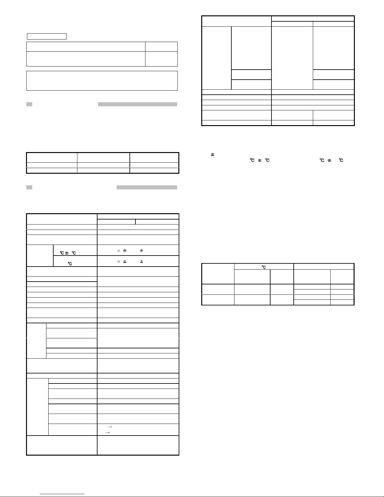
2. Performance Specification
The A1S62TC performance specification is indicated in Table 2.1.
Table 2.1 A1S62TC performance specification
Specification
Item
A1S62TCRT-S2 A1S62TCRTBW-S2
Control output Transistor output
Temperature input points 2-channel/module
Supported platinum tem pe rat ur emeasuring resistor
Refer to Table 2.2.
Ambient temperature:
23
5
Full scale ( 0.3%) 1 digit*1
Specification
accuracy
Ambient temperature:
0 to 55
Full scale ( 0.7%) 1 digit*1
Sampling period
0.5s/2-channel (It is not connected with the
number of channels used)
Heating control output period
Cooling control output period
1 to 100s
Sensor current 0.25mA
Allowable input wire resistor effects
Less than 20Ω
Input filter 0 to 100s (0: input filter off)
Sensor compensation value setting -50.00 to 50.00%
Operation when sensor input is
disconnected
Upscale processing
Temperature control method PID on/off pulse
PID constant setting Auto-tuning setting is possible
Heating proportional band
(Ph)
Cooling proportional band
(Pc)
0.1 to 1000.0%
Integral time (I) 1 to 3600s
PID
constant
range
Derivative time (D) 0 to 3600s (0: PI control)
Set value setting range
Within the temperature range set by the
platinum temperature-measuring resistor
to be used.
Cooling method setting Air cooling/water cooling
Output signal ON/OFF pulse
Rated load voltage 10.2 to 30.0VDC (peak voltage : 30.0VDC)
Maximum load current
0.1A/1 point
0.4A/common
Max i mu m i nr u sh c ur r en t 0.4A 10ms
Maximum current when
OFF
Less than 0.1mA
Maximum voltage drop
when ON
1.0VDC (TYP) 0.1A
2.5VDC (MAX) 0.1A
Transistor
output
Response time
OFF
ON: Less than 2ms
ON
OFF: Less than 2ms (resistor load)
Insulation method
Between the input and grounding:
transformer insulation
Between the input and channel:
transformer insulation
Table 2.1 A1S62TC performance specification (continued)
Specification
Item
A1S62TCRT-S2 A1S62TCRTBW-S2
Current sensor
URD manufactured
current sensor*2
CTL-12-S36-8
(0.0 to 100.0A)
CTL-6-P-H
(0.00 to 20.00A)
(Former mode l,
CTL-6-P is also
applicable.)
Input method
Multiplex method
A/D conversion
Heater wire
breakage
disconnection
specification
Number of alert
delays
-
3 to 255
I/O occupied points Special 32 points
Connection terminal 20 po ints terminal block
Supported cable size (mm) [inch] 0.7 5 to 1.5 [0 .0 3 0 t o 0 .0 5 9]
Supported solder-less terminal R1.25-3, 1.25-YS3, RAV1.25-3, V1.25-YS3A
Internal consumed current (5VDC)
[A]
0.19 0.28
Weight (kg) [lb] 0.25 [0.55] 0.28 [0.62]
For the noise resistance, dielectric withstand voltage, and insulation
resistance for the PC system which uses this module, refer to the power
module specification found in the CPU Module User’s Manual.
*1: “
1 digit” error depends on the input range.
For setting unit of 1
, 1 For setting unit of 0.1 , 0.1
*2: Only the URD International, Ltd. current sensor can be used.
Sales channels for current sensors manufactures by URD
International Ltd. are listed as follows:
U.S.A. Julia Industries Inc.
Tel:949-831-0111
BRAZIL Ananda Industial Lt da.
Tel:011-5584-0959
UNITED
KINGDOM Omni Components
Tel:024-7622-5757
GERMANYAllied Electronics Gm bH
Tel:0221-497-3084
FRANCE Diltronic S.A.
Tel:01-34-51-33-00
ITALY ELNET s.n.c.
Tel:041-50-19-939
KOREA Joyang Trading Co.
Tel:02-521-2294
Sewon Tech Co.,Ltd.
Tel:02-868-9355/9356
Keum Ho Corporation
Tel:51-319-4155/4156
HONG-KONG Weltronics Components Ltd.
Tel:2410-0623
TAIWAN Tope Co.,Ltd.
Tel:886-2-8228-0658
INDIA AmtechElectronics PVT.Ltd.
Tel:02712-25324
Table 2.2 The types of supported platinum temperature-measuring
resistor and the measured temperature range
°F
Platinum
temperature-
measuring
resistor
Measured
temperature
range
Data
resolution
Measured
temperature range
Data
resolution
-300 to 1100 1
Pt 100
-200.0 to 600.0
-200.0 to 200.0
0.1
-300.0 to 300.0 0.1
-300 to 900 1
JPt100
-200.0 to 500.0
-200.0 to 200.0
0.1
-300.0 to 300.0 0.1
For the general specifications, refer to the User’s Manual for the PC
CPU used.
Page 3

3. Name of Each Part
A1S62TCRT-S2
NC
NC
NC
NC
NC
NC
NC
b2
B2
A2
NC
NC
b1
B1
A1
+
L2C
L2H
L1C
L1H
-
CH1
H OUT
C OUT
ALM
RUN
H OUT
C OUT
ALM
CH2
A1S62TCRTBW-S2
NC
NC
NC
NC
NC
NC
NC
b2
B2
A2
NC
NC
b1
B1
A1
;
L2C
L2H
L1C
L1H
-
CH1
H OUT
C OUT
ALM
BR.W
RUN
CH2
H OUT
C OUT
ALM
BR.W
1) 1)
2)
2
4
6
8
10
12
14
16
18
20
1
3
5
7
9
11
13
15
17
19
2
4
6
8
10
12
14
16
18
20
1
3
5
7
9
11
13
15
17
19
A1S62TCRT-S2 A1S62TCRTBW-S2
A1S62TCRT-S2 LED A1S62TCRTBW-S2 LED
A
1S62TCRT-S2
CH1
H OUT
C OUT
ALM
RUN
H OUT
C OUT
ALM
CH2
A
1S62TCRTBW-S2
CH1
H OUT
C OUT
ALM
BR.W
RUN
CH2
H OUT
C OUT
ALM
BR.W
Number
Name Description
RUN A1S62TC operation status display
ON: Normal operation in progress
Flashing (2 sec. ON/2 sec. OFF): Write data error
Flashing (1 sec. ON/1 sec. OFF): Hardware error
OFF: 5V power shutoff, Watchdog timer error
OUT Transistor output status display
ON: Transistor output ON
OFF: Transistor output OFF
ALM Alert alarm status display
ON: Alert alarm is ON.
Flashing: The measured temperature range is
exceeded.
The platinum temperature-measuring
resistor is not connected.
The platinum temperature-measuring
resistor cable is disconnected.
OFF: Alert alarm is OFF
1) LED
BR.W Heater wire breakage detection status display
ON: Heater wire breakage is det ect ed.
OFF: Heater wire breakage is not detected.
2) Wire
breakage
detection
connector
Connector for current senso r
Wire breakage detection
connector installation screw
Cable fixing screw
BW1(For CH1)
BW2(For CH2)
NC(Unusable)
4. Loading and Installation
Precautions when handling the A1S62TC and installation environment
are explained.
For details of implementing and setting up this unit, please refer to the
User’s Manual for the PC CPU used.
4.1 Handling Instructions
1) The module case is made of plastic. Be sure not to drop it or
subject it to strong vibration.
2) Do not remove the module printed circuit boards from the case.
It may cause t rouble.
3) When connecting the wiring, do not allow wire cuttings or other
foreign matter to enter from the top of the module. Remove any
foreign matter from the module.
4) Tighten the module installation screws within the following
tightening torque range.
Screw position Tightening torque range
Module installation screw (M4 screw)
78 to 118N•cm
Terminal block terminal screw (M3.5 screw)
59 to 88N•
Terminal block installation screw (M4 screw)
78 to 118N•cm
Wire breakage detection connector installation
screw (M2.6 screws)*
15 to 30N•cm
Cable fixing screw (M2 screws)*
11 to 14N•cm
*:Use only for A1S62TCRTBW-S2 .
4.2 Installations Enviroment
Never install the AnS series PC system in the following environments:
1) Locations where the ambient temperature is outside the range of
0 to 55
.
2) Locations where the ambient humidity is outside the range of 10
to 90%RH.
3) Locations where dew condensation takes place due to sudden
temperature changes.
4) Locations where there are corrosive and/or combustible gasses.
5) Locations where there is a high level of conductive power (such
as dust and iron filings, oil mist, salt, and organic solvents).
6) Locations exposed to the direct rays of the sun.
7) Locations where strong power and magnetic fields are generated.
8) Locations where vibration and shock are directly transmitted to
the main module.
5. Wiring
The precaution when wiring and the module connection example are
shown below.
5.1 Precaution when wiring
In order to have the best result from the A1S62TC functions and to
make the system highly reliable, an external cabling with low noise
effects are necessary.
The external wiring precautions are shown below:
1) Use separate cables for the alternating current and A1S62TC
external input signals to avoid A/C surges and induction effects.
2) Do not bunch the cables with the main circuit, high-voltage cable
or load cables from other than PC, or install them close to each
other.
Install the cables far apart from high-frequency circuits, such as the
high-voltage cable and inverter load main circuit, as much as
possible.
This increases the noises, surges, and induction.
3) Perform a one-point grounding for the shielded line and shields of
the seal and cable at the PC. However, there may be cases
when grounding should be performed externally depending on
the noise condition.
Page 4

5.2 Module connection example
1) A1S62TCRT-S2
L1C
L2H
L2C
COM-
A1
B1
b1
A2
B2
b2
Internal circuit
R
Cooling
A
*
B
B
Heating
Control
target
A1S62TCRT-S2
R
DC24V
L1H
Internal circuit
FilterFilter
*
*1: Ple as e us e th e ca bl e wi t h s hi el d.
2) A1S62TCRTBW-S2
L1C
L2H
L2C
DC24V
COM-
A1
B1
b1
A2
B2
b2
BW1
*2
Internal circuit
R
A
*1
B
B
A1S62TCRTBW-S2
R
L1H
Internal circuit
Filter
Filter
*1
*1
Cooling
Heating
Control
target
*1: Ple as e us e th e ca bl e wi t h s hi el d.
*2: Refer to the following for the connection of the wire breakage
detection connector.
[Connect to]
6.5mm
Cable with shield
BW1(For CH1)
BW2(For CH2)
NC(Unusable)
BW1
BW2
NC
NC
NC
NC
6. External Dimensions
6.1 A1S62TCRT-S2
A1S62TCRT-S2
CH1
H OUT
C OUT
ALM
RUN
H OUT
C OUT
ALM
CH2
0
1
2
3
4
5
6
7
8
9
A
B
C
D
E
F
93.6(3.69)
130(5.12)
6.5
(0.26)
34.5
(1.39)
6.2 A1S62TCRTBW-S2
0
1
2
3
4
5
6
7
8
9
A
B
C
D
E
F
93.6(3.69)
42(1.65)
130(5.12)
18
(0.71)
8
(0.31)
6.5
(0.26)
34.5
(1.39)
A1S62TCRTBW-S2
CH1
H OUT
C OUT
ALM
BR.W
RUN
CH2
H OUT
C OUT
ALM
BR.W
6
( 0.24)
Unit : mm(inch)
Warranty
Mitsubishi will not be held liable for damage caused by factors found not to be the cause
of Mitsubishi; machine damage or lost profits caused by faults in the Mitsubishi products;
damage, secondary damage, accident compensation caused by special factors
unpredictable by Mitsubishi; damages to products other than Mitsubishi products; and to
other duties.
For safe use
y This product has been manufactured as a general-purpose part for general industries,
and has not been designed or manufactured to be incorporated in a device or system
used in purposes related to human life.
y Before using the product for special purposes such as nuclear power, electric power,
aerospace, medicine or passenger movement vehicles, consult with Mitsubishi.
y This product has been manufactured under strict quality control. However, when
installing the product where major accidents or losses could occur if the product fails,
install appropriate backup or failsafe functions in the system.
U.S.A Mitsubishi Electric Automation Inc.
500 Corporate Woods Parkway Vernon
Hills, IL 60061
Tel : +1-847-478-2100
Brazil MELCO-TEC Rep. Com.e Assessoria
Tecnica Ltda.
Av. Rio Branco, 123-15 ,and S/1507,
Rio de Janeiro, RJ CEP 20040-005,
Brazil
Tel : +55-21-221-8343
Germany Mitsubishi Electric Europe B.V. German
Branch
Gothaer Strasse 8 D-40880 Ratingen,
GERMANY
Tel : +49-2102-486-0
U.K Mitsubishi Electric Europe B.V. UK
Branch
Travellers Lane, Hatfield, Herts., AL10
8XB,UK
Tel : +44-1707-276100
Italy Mitsubishi Electric Europe B.V. Italian
Branch
Centro Dir. Colleoni, Pal. Perseo - Ingr.2
Via Paracelso 12, 20041 Agrate B.,
Milano, Italy
Tel:+39-039-60531
Spain Mitsubishi Electric Europe B.V. Spanish
Branch Carretera de Rubi 76-80
08190 - Sant Cugat del Valles,
Barcelona, Spain
Tel:+34-935-653135
South Africa Circuit Breaker Industries LTD.
Private Bag 2016, Isando 1600,
Johannesburg, South Africa
Tel : +27-11-928-2000
Hong Kong Ryoden Automation Ltd.
10th Floor, Manulife Tower, 169 Electric
Road, North Point, HongKong
Tel : +852-2887-8870
China Ryoden International Shanghai Ltd.
3F Block5 Building Automation
Instrumentation Plaza 103 Cao Bao Rd.
Shanghai 200233 China
Tel : +86-21-6475-3228
Taiwan Setsuyo E n terprise Co., Ltd.
6F., No.105 Wu-Kung 3rd.RD, Wu-Ku
Hsiang, Taipei Hsine, Taiwan
Tel : +886-2-2299-2499
Korea HAN NEUNG TECHNO CO.,LTD.
1F Dong Seo Game Channel Bldg.,
660-11, Deungchon-dong Kangsec-ku,
Seoul, Korea
Tel : +82-2-3660-9552
Singapore Mitsubishi Electric Asia Pte, Ltd.
307 ALEXANDRA ROAD #05-01/02,
MITSUBISHI ELECTRIC BUILDING
SINGAPORE 159943
Tel : +65-473-2480
Thailand F. A. Tech Co.,Ltd.
898/28,29,30 S.V.City Building,Office
Tower 2,Floor 17-18 Rama 3 Road,
Bangkpongpang, Yannawa,
Bangkok 10120
Tel : +66-2-682-6522
Indonesia P.T. Autoteknindo SUMBER MAKMUR
Jl. Muara Karang Selatan Block A Utara
No.1 Kav. No.11 Kawasan Industri/
Pergudangan Jakarta - Utara 14440
Tel : +62-21-663-0833
India Messung Systems Put,Ltd.
Electronic Sadan NO:111 Unit No15,
M.I.D.C BHOSARI,PUNE-411026
Tel : +91-20-7128927
Australia Mitsubishi Electric Australia Pty. Ltd.
348 Victoria Road, PostalBag, No 2,
Rydalmere, N.S.W 2116, Australia
Tel : +61-2-9684-7777
Country/Region Sales office/Tel Country/Region Sales office/Tel
When exported from Japan, this manual does not requir e application to the Ministry
of Economy, Trade and Industry for service tran saction permiss ion.
Specifications subject to change without notice.
Printed in Japan on recycled paper.
HEAD OFFICE : 1-8-12 , OFFICE TOWER Z 14F HARU MI CHUO-KU 104-6212, J APAN
NAGOYA WORKS : 1-14, YADA-MINAMI5, HIG ASHI-KU, NAGOYA, JAPAN
 Loading...