

Page 1

0
v
n
MITSUBISHI
MOTORS
Worl<shop
Mqnuol
chossis
SUPPLEMENT
3000GiT'96
v
/----.-:
1C
- ..--:
---:
_
--+'----
.-___
=--:=-
:
\'
/z-:=-
-::--t-
:.8
Page 2

v
MITSUBISHI
(-,
i.
v
3000GiT
WORKSHOP
SUPPLEMENT
FOREWORD
This Workshop
removal,
sembly and installation,
Use the
manual as required.
TECHNICAL
WORKSHOP
All information,
tions
time
to make
or obligation.
disassembly, inspection,
following
CHASSIS
ENGINE
ELECTRICAL
PARTS
contained in
publication.
of
changes
Manual
manuals
INFORMATION
MANUAL
GROUP PWUEg119
GROUP
WIRING
CATALOGUE
illustrations
this manual
We, however,
at any time
MANUAL
contains
etc. for
in
combination with this
PYUE92O1
(Loose-leaf
PWUE9203
PWUE92O3-1
(Supplement)
PWUE92O3-2
(Supplement)
PWUE92O3-3
(Supplement)
PWEEDN!N
(Loose-leaf
PHUE92O1
(Loose-leaf
PHUE9406
PHUE94O6-1
(Supplement)
8608K40!A!
B608K454An
B608K406A!
8808K404A!
8808K454A!
BFASK4O4AD
BFA8K454A!
8808K405A!
8808K406A!
BFASK4O6AN
and
procedures
adjustment, reas-
service mechanics.
MANUAL
product
are
current as
reserye
without
edition)
(Basic)
edition)
edition)
(Basic)
descrip-
the right
prior
for
at the
notice
General
Fuel
Engine
Electrical
Body
Chassis
Electrical
G
IE
IE
JE
-E
GI
-l
Milsubishi
@
A[!,LT-,'.H-BJ-iJJI
Molors
Corporation July 1995
Page 3

WARNINGS REGARDING
(sRs)
WARNING!
(1)
lmproper
lead to
driver
(2)
lf it is
after
beforehand.
(3)
Service or
an authorized MITSUBISHI dealer.
(4)
MITSUBISHI
Supplemental Restraint
of the
NOTE
Section titles with asterisks
warnings.
EQUTPPED VEHTCLES
service or
personal
(from
possible
painting,
rendering
maintenance
dealer
or any
SRS
remove the
maintenance
injury
that the
or death to service
the SRS
SRS
personnel
System
SRS-related
components
SRS
of any
(.)
in the table of contents in each
OF SUPPLEMENTAL
of any component of the
inoperative).
components
component or
SRS
must thoroughly review this manual, and
(SRS),
component.
before beginning any service or maintenance
personnel
subjected to heat
are
(air
(from
bag module,
SRS-related
RESTRAINT
or any
SRS,
inadvertent
over 93oC
SRS diagnosis unit, front impact
component must
group
SRS-related component,
firing
of the air
(200'F)
especially
indicate
in baking
be
operations requiring
SYSTEM
bag) or to the
or
performed
its
GROUP
of any component
can
in
drying
sensors)
only at
528-
ll
ri
v
r)
Page 4

GENERAL
-
Vehicle
ldentification
00-1
VEHICLE
IDENTIFICATION
MODELS
VEHICLES
Zl6AMNGFL6
Zl6AMNGFR6
Zl6AMJGFL6
Zl6AMJGFR6
VEHICLES
Zl64MNGFL
Zl6AMNGFR
FOR
Model
FOR
Model
code
code
EUROPE
6G72
GENERAL
EXPORT
6G72
Engine
(2,972
mt
Engine
(2,972
m(
GROUP
GENERAL
model
)
model
)
Transmission
WsMG1
W6MG1
Transmission
WsMG1
OO
model
model
MPI
MPI
Fuel
Fuel
supply
supply
system
system
VEHICLES
Zl6AMNGFLW
VEHICLES
Zl64MNGFR8
FOR
Model
FOR
Model
GCC
code
AUSTRALIA
code
6G72
6G72
Engine
(2,972
m(
Engine
(2,972
me
model
)
model
)
CHASSIS
The
engine
Transmission
WsMG1
Transmission
WsG1
NUMBER
chassis
number
compartment.
model
model
is
stamped
Fuel
supply system
MPI
Fuel
supply
MPI
on
the toeboard
system
inside
the
<VEHICLES
FOR
EUROPE
AND
AUSTRALIA>
AJMBMN216
T_ITTTI-
ttttll
123456
APY
TTT
ttl
ltl
789
000001
---l---
I
I
10
A
Page 5

00-2
GENERAL - Vehicle
ldentification
1. Asia
2.
Japan
MITSUBISHI
3.
A - For
-
B
F - For Australia, right
4.
Body style
M - 2-door hatchback
Transmission
5.
6.
<VEHICLES
-
N
J - 6-speed manual transmission
Development
216- 2,972 me
Europe, right hand
For
Europe, left hand
type
S-speed
FOR
manual transmission
order
(Full
GENERAL EXPORT AND GCC>
time 4WD)
C
TTT_T-]_TT
tttlttl
tttrrtl
1234567
drive
drive
hand drive
M N 216 A P Y
7. Sort
A - Passenger
8.
9.
10.
Model
Plant
Serial
00001
--T--
year
P - 1993
R - 1994
-
1995
s
T - 1996
-
Y
Ohe Motor
number
I
I
B
ll
car
Vehicle Works
c
MITSUBISHI
1.
4.
-
For
C
D - For
drive
Body
style
M - 2-door hatchback
Transmission
-
N
S-speed
Development order
216 - 2,972 me
General
General
type
Export, right hand
Export
manual
(Full
or GCC,
transmission
4WD)
time
left hand
drive
Sort
5.
A - Passenger
Model
6.
P - 1993
R - 1994
-
s
T - 1996
Plant
7.
-
Y
Serial
number
car
year
1995
Motor Vehicle Works
Ohe
o
a
Page 6

I
V
MAJOR
SPECIFICATIONS
GENERAL - Major
Specifications
00-3
L
Items
Dimensions
Overall
Overall width
Overall
Wheelbase
Track-front
Track- rear
Ground clearance
Overhang-front
Overhang
Angle
Angle
Weight
Kerb weight
Gross
Max. axle weight
length
height
-
rear
approach
of
of departure degrees
vehicle weight
front
rear
mm
(unladen)
(unladen)
degrees 10
k9
(in.)
1
2
3
4
5
6
7
8
9
'11
(lbs.)
Zl6AMNGFL6
Zl6AMNGFR6
(179.9)
4,570
(72.4)
1,840
(50.6)
1,285
(97.2)
2,470
(61.4)
1,560
(62.2)
1,580
(5.5)
140
(40.6)
1,030
(42.1)
1,070
1'1.00
17.60
(3,792)
1,720
(4,674)
2,120
(2,535)
1,150
(2,249)
1,020
Zl6AMJGFL6
Zl6AMJGFR6
(179.9)
4,570
(72.4)
1,840
(50.6)
1,285
(97.2)
2,470
'1,560
(61.4)
(62.2)
1,580
(5.5)
140
(40.6)
1,030
(42.1)
1,070
'1
1.00
17.60
(3,858)
1,730
(4,674)
2,120
(2,535)
1,150
(2,249)
1,020
Zl6AMNGFL
Zl6AMNGFR
Zl6AMNGFLW
(179.9)
4,570
(72.4)
1,840
(50.6)
1,285
(97.2)
2,470
(61.4)
1,560
(62.2)
1,580
(5.7)
145
(40.6)
1,030
(42.1)
1,070
12.0"
17.4"
(3,737)
1,695
(4,57s)
2,075
(2,535)
1,150
(2,249)
1,020
Zl64MNGFRB
(179.9)
4,570
(72.4)
1,840
(50.6)
1,285
(97.2)
2,470
(61.4)
1560
(62.2)
1,580
(5.7)
145
(40.6)
1,030
(42.1)
1,070
12.00
17.40
(3,748)
1,700
(4,575)
2,075
(2,535)
1,150
(2,249)
1,020
Seating capacity
Engine
Model
Total
displacement m(
Transmission
Model
Type
4
6G72
2,972
WsMG1
S-speed manual
4
6G72
2,972
W6MG1
6-speed manual
4
6G72
2,972
WsMG1
5-speed manual
4
6G72
2,972
WsMG1
S-speed manual
Page 7

\/
,
v
t,
GENERAL
Outline
SPECIFICATIONS
General Specifications
TROUBLESHOOTING
Engine
(Check
Self-diagnosis
Problem Diagnosis
Check Chart
Problem
of Changes
Warning Lamp
Engine Lamp)
Classified by
Symptoms
..............
...........
Content
.............
Chart
FUEL
CONTENTS
2
2
ON.VEHICLE
coMPoNENTS
Fuel Pump
2
2
2
2
2
2
Air
Conditioner
Engine
Voltage
INSPECTION
Control
Check
........
Switch
Terminal
Unit
MPI
OF
Power Relay .......
and
13-1
4
4
8
Page 8
13-2
FUEL
-
General/Specifications/Troubleshooting
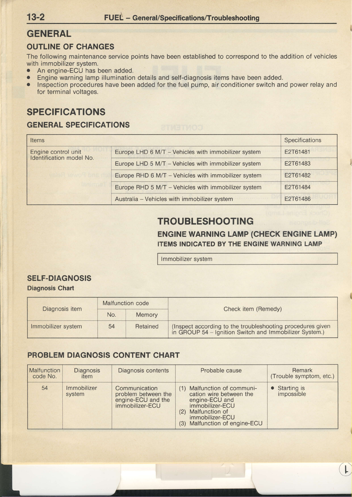
GENERAL
OUTLINE OF CHANGES
The following maintenance service
with immobilizer system.
o
An
engine-ECU
.
Engine warning lamp illumination
.
Inspection
for terminal voltages.
has
been
procedures
have been added for the fuel
points
added.
have been established to correspond to
details
and
self-diagnosis
pump,
items have
air conditioner switch
been
SPECIFICATIONS
GENERAL SPECIFICATIONS
Items Specifications
the addition
added.
power
and
vehicles
of
relay and
Engine
ldentification model No.
control unit
SELF.DIAGNOSIS
Diagnosis
Chart
Diagnosis item
Europe LHD 6 M/T - Vehicles with immobilizer system
Europe
Europe
Europe RHD 5 Mft - Vehicles with immobilizer system
Australia - Vehicles with immobilizer system
LHD 5
RHD
MlT - Vehicles with immobilizer system E2T61483
6 M/T - Vehicles with immobilizer system
TROUBLESHOOTING
ENGTNE WARNTNG LAMP
ITEMS INDICATED BY THE ENGINE WARNING
lmmobilizer system
Malfunction code
No. Memory
Check
(CHECK
(Remedy)
item
E2T61481
E2T61482
E2T61484
E2T61486
ENGINE LAMP)
LAMP
lmmobilizer
PROBLEM DIAGNOSIS
Malfunction
code
54
system 54
Diagnosis
No.
lmmobilizer
system
CONTENT CHART
item
Retained
Diagnosis contents Probable cause
Communication
problem
engine-ECU
immobilizer-ECU
between
and the
(lnspect
in
the
according to the troubleshooting
-
GROUP 54
(1)
Malfunction
cation
engine-ECU and
immobilizer-ECU
(2)
Malfunction of
immobilizer-ECU
(3)
Malfunction of engine-ECU
lgnition
of communi-
wire
between
Switch
the
procedures given
lmmobilizer System.)
and
(Trouble
Remark
symptom, etc.)
Starting
impossible
is
O
Page 9

FUEL
-
Troubleshooting
13-3
CHECK
(Vehicles
Check items
Power
supply
Engine
control unit
pump
Fuel
Air flow
sensor
Intake
air temperature
Barometric
Engine
coolant
position
Throttle
position
ldle
position
Cam
Crank angle
lgnition
switch-ST
Vehicle
speed sensor
Power
steering fluid
Air
conditioner
Detonation
Electrical
Fan
Oxygen
Mixture
Injectors
ldle
lgnition
Purge
EGR
Fuel
Waste gate
Anti-lock
Fuel
:
o
:
n
sensor
load
motor relay
sensor
adjusting
speed
control
coil and
control
control
pressure
control
braking
pressure
Warm
engine
Cold engine
CHART
CLASSIFIED
with immobilizer
Problem
and ignition
pressure
temperature
sensor
switch
sensor
sensor
switch and
switch
(radiator
screw
power
solenoid valve
solenoid
control valve
signat
(number
(number
power
sensor
sensor
pressure
fan,
(variable
(stepper
servo
transistor
valve
solenoid
insrde
switch-lG
earth
sensor
switch
power
condenser
resistor)
motor
valve
inside
indicates
indicates
relay
system)
symptoms
fan)
type)
check order)
check order)
BY PROBLEM
Starting
E
o
-=^
o
r
6
c
=
3C
o
E-
o
.g
E
a
SYMPTOMS
ldling
stability
o
-o
o@
:9'
otr
@a
@tr
otr
o
o
@E
otr
otr
@a
@E @e
G'LqI
@tr
@E @ts
r2)
@
@
@
@
@
@E
@a OE
@trotr
OE
@
@tr
@
o
@E
Refer
Refer to
Refer
OE @a
to 3000GT'93
3000GT'95 Workshop
to 3000GT
o
.g
p
!>
Y'=
*7
otr
OE
@m
@E
@E @tr
@tr
@E OE
@tr
@E
@E
otr
@
@@
@tr
@a
@E
@E
@
o@
OE
Workshop
Workshop
6
f
F
6
=
o
r
L6
otr
@B
@a
@a
os
@ts
@E
@tr@a
Manual
E
F
6
O
@E
@E
@tr
on
@@
Manual
Manual
Driving
o
c
E
o
l
E
U)
6
@E
@ts
@a
otr
\9
@@
otr
o
(Pub.
No. PWUE9203)
(Pub.
No. PWUE920S-3)
(Pub.
No. PWUE9119-D)
o
g
l
a
@E
otr
@E
@E
-E
o
c
:<
@E
@e
@E
on
@E
e
PE
co
cc3
c
e
-1
P.1
.3P.1
-1
P.1
-3P.1
r
'T
-3P
.1
P.1
-3P.13-62
-1P.13-72
.3P.1
.1P.13-74
-3P.13-72
'1P.13-77
-3P.1
-
1
P.1
.3P.13-78
,1P
-rP
*3P
*3P
-r
P.1
-3P.13-90
P.13-00
-1
P.1
.3P.'13-92
.rP.13-96
-3P.13-94
.1
P.1
-3P.1
.2P
.3P
-1
P.1
.3P.1
.rP.13-1
.3P.13-108
-1
P.1
.3P.1
-1P.13-127
.3P.13-1
.1
P.13-1
.3P.1
.1P.1
.3P.1
-1P.13-'134
-3P.13-126
'3P
-3P
O
6
o
o
I
c
E
o
3-54
3-52
3-57
3-55
3-00
3-58
3-56
3-64
J-OZ
3-69
3-70
3-75
3-80
3-82
3-80
3-86
3-84
3-89
3-87
1
3-90
1 3-88
3-92
3,94
3-98
3-96
J-J
3-1 00-1
3-1
00
3-98
3-1
06
3-109
3- 1 01
16
21
3-1
3-1 1 3
19
29
3- 1 21
3-1 31
23
3-1
3-138
3-1 30
3-1 39
J-IJI
Page 10

13-4
ON-VEHICLE
INSPECTION
FUEL
-
On-vehicle
OF
Inspection
MPI
of MPI
COMPONENTS
Gomponents
,l
,
v
FUEL
PUMP
(Vehicles
with immobilizer
-1
,/o
,r'n
w
system)
u>Z/
pump
Fuel
check terminal
\:::-=-====<=
(:
\_----'==
----r-
;;G,
Fuel
pump
connector
lJ
tL
tg
Page 11

FUEL
-
On-vehicle
Inspection
of MPI
Components
13-5
Equipment
@
connector
side
lgnition
switch
flGl
Control
reray
(for
fuel
@
pu
mp)
r..;.€---r
ll1l2l3l I
lr-#l
| 4 | 5 ll
Equipment
connector
@
Equipment
)
side
connector
Harness
@
connector
side
CIrrrcl
(61
L4f5
Fuel
pump
side
\9
Engine
control
unit
Engine
control
[ffi,]:ipump)lrcra-sl
unit
connector
Equipment
connector
side
"t"l
"t"l
;F[
'l'l'
,l
+
"t.
't-
:t:
9FU0lol
EF
pump
Fuel
check
1a
termina
7FU1352
Page 12

13-6
FUEL
-
On-vehicle Inspection
of MPI
Gomponents
HARNESS
INSPECTION
Check the fuel
o
Apply
battery voltage
checking terminal
pump.
the
Check
pump.
o
the
earth
pump
Fuel
Disconnected
pump.
to the
and operate
circuit of the fuel
connector:
@
OK
@
0(
Repair
harness.
the
(@tr-
Earth)
l4
a
Harness
@
conneclor
side
@
r
@
F
I
7FUOg5
7FU0960
Engine
control
unit harness
side
connector
Check for
fuel
terminal.
o
Check for
checking terminal
relay
the resistor
r
Control relay
connector: Disconnected
o
Resistor
con nector: Discon
r
Fuel
Disconnected
Check
short-circuit
control relay
engine
o
Control
connector: Disconnected
.
Engine
Disconnected
continuity
pump
and
the
connector:
(for
pump
for
control unit.
Disconnected
continuity
pump),
fuel
(for
fuel
(for
fuel
connector:
an
open-circuit,
to
earth,
(for
relay
control
checking
and the
pump).
(for
fuel
(for
unit connector:
between the
between the
control
and between
pump)
fuel
pump)
nected
a
or
between the
pump)
fuel
and
pump)
OK)
@
OK
the
Z \
\_-/
Repair
harness.
the
(@tr-oa)
Repair
narness.
(otr-@)
(@tr-@)
Repair
harness.
(@tr-E)
the
the
tu
v)
Page 13

FUEL
-
On-vehicle
Inspection
of Mpl
Components
13-7
6
o=
Harness
connector
side
Harness
@
connector
side
Check for
control
resistor (for
Measure
the
control
r
Control relay
Disconnected
lgnition
Check
short-circuit to
control relay and
unit.
o
Control
Disconnected
o
Engine
Disconnected
continuity
(for
relay
fuel
Control relay
connector:
Resistor (for
connector:
OFF
ON
for
Disconnected
Disconnected
power
the
relay.
switch
an open-circuit,
earth
relay
control
between
pump)
fuel
pump).
(for
fuel
pump)
fuel
supply voltage
connector:
Voltage (V)
between the
the engine
connector:
unit connector:
and
pump)
0-1
SV
or a
control
the
the
@
0(
of
'9K)
OK
@
Repair
harness.
the
(@E-@tr)
Repair
harness.
(lgnition
switch-@fl)
or check
the ignition
switch.
Repair
harness.
(@tr-tr
the
the
)
r^'-l
t-\
l/\---\
tnl
t
f-\---l
l-)i-l
t _,:z__J
Check for
control relay
./
___,
fuel
.
o
continuity
and the
pump).
Control relay
Disconnected
Control relay
connector: Disconnected
between
control relay
connector:
(for
fuel
pump)
the
(for
Repair
harness.
the
(@n-@tr)
(@tr-@tr)
Check for
short-circuit
control relay
fuel
o
Control
connector: Disconnected
o
Fuel
Disconnected
pump.
pump
an
open-circuit,
to earth,
(for
fuel
(for
relay
connector:
or a
between
pump)
fuel
and the
pump)
the
Repair
narness.
the
(@tr-oE)
Page 14

13-8
AIR
CONDITIONER SWITCH
(Vehicles
with immobilizer system)
FUEL
-
On-vehicle
Inspection of
AND POWER RELAY
MPI
Components
Battery
'uu
1i-#\
^l
Air conditioner
compressor
//
l\ A-,\
) | /\ -\l
Air conditioner
control
relay
Engine
control
unit
Enoine control unit connector
unit
tq
-t-
"t'
"t"
"t'
4
,l:
HARNESS
INSPECTION
power
Measure
the air conditioner
e
o
o
o
the
circuit.
Air conditioner
Engine control
Disconnected
lgnition
Dual
switch:
air conditioner
Voltage
SV
supply
switch:
connector:
unit
ON
switch: ON
(V)
voltage
ON
of
OK
o(
a
Check the
air
conditioner
circuit.
l,)
Page 15
FUEL - On-vehicle
Inspection of
MPI Components
13-9
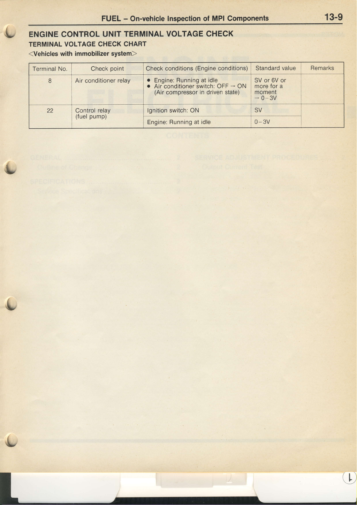
ENGINE CONTROL
TERMINAL
(Vehicles
Terminal
VOLTAGE CHECK
with immobilizer
No. Check
B
22 Control
Air
(fuel
UNIT
conditioner
relay
pump)
TERMINAL VOLTAGE CHECK
CHART
system)
point
relay
Check
conditions
.
Engine:
o
Air
conditioner
(Air
compressor
lgnition
Engine:
Running at idle
switch: ON
Running at idle
(Engine
switch: OFF
in driven state)
conditions) Standard
6V or
ON
SV or
for
more
moment
*
0-3v
SV
a
-*
0- 3v
value
Remarks
Page 16
16-1
{"
ENGINE
ELECTRICAL
CONTENTS
GENERAL
Outline
SPECIFICATIONS
Service
of
Change
Specifications
.............
2
SERVICE
2
2
2
Output
ADJUSTMENT
Current
Test
PROCEDURES
.......
2
2
Page 17
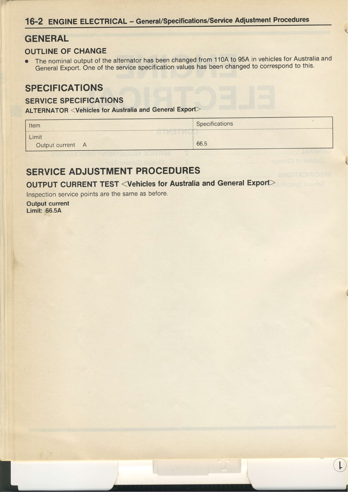
16-2
ENGINE
GENERAL
ELECTRICAL
-
General/Specifications/Service
Adiustment
Procedures
OUTLINE
o
The
General
OF CHANGE
nominal
output
Export.
bne
the alternator
of
the service
of
SPECIFICATIONS
SERVICE
ALTERNATOR
Item
Limit
Output
SERVICE
OUTPUT
Inspection
Output
Limit: 66.5A
SPECIFICATIONS
(Vehicles
current
A
for Australia
ADJUSTMENT
CURRENT
service
current
points
TEST
are
the same
has been
specification
and General
changed
valuies
Export)
PROCEDURES
(Vehicles
as before'
Australia
for
to 95A
1 1OA
from
has been
Specifications
66.5
and
changed
General
in vehicles
to correspond
for Australia
Export)
to
and
this.
Page 18

BODY
-
General/Specifications/Troubleshooting
42-1
GENERAL
OUTLINE
o
power
A
OF
CHANGE
tilt
and
outer
sliding
sunroof
SPECIFICATIONS
SERVICE
Items
Roof
Sunroof
SPECIFICATIONS
lid
sliding resistance
motor
clutch slippage
N
force
N
TROUBLESHOOTING
INSPECTION
CHART
FOR
TROUBLE
GROUP
BODY
has
provided
been
SYMPTOMS
42
as an
option
Standard
147
39- 49
in vehicles
or
for Europe.
value
more
I
I
Trouble
sunroof
Sunroof
INSPECTION
Inspection
Front
drive/s
After
turned
impossible,
Inspection
symptom
does not
does
Procedure
sunroof
door is
the driver's
off, the sunroof
door is opened
the
driver's door
Procedure
operate
not
operate at
PROCEDURE
does not
opened.
can still
within
30
all.
1
operate within
within
30 seconds
be operated
switch
or
the
sunroof
2
seconds
FOR
TROUBLE
30
after
for a further
control
Check
c-63, E-16,
Check the harness
roof
switch.
Replace
after
driver's
seconds
the ignition
30
seconds. lf
unit mav
control
be defective.
the following
E-39, E-40,
unit
the
sunroof
door is
openeo.
SYMPTOMS
after
switch is
it is
connectors.
between
and the
control
F-35
driver's
Probable
.
o
.
the
sun-
door
unit.
Inspection
1
2
cause
Malfunction
Malfunction
Malfunction
procedure
of
door switch
of sunroof control
of wiring harness
Repair
Repair
(driver's
side)
unit
or connector
Sunroof
One of the following
Sunroof
Sunroof motor
Sunroof
Power
does not
switch
control
supply
unit
circuit
operate
items
may
(including
at all.
be defective
theYuse)
Probable
.
Malfunction
.
Malfunction
r
Malfunction
.
Malfunction
cause
of sunroof
of sunroof
of
sunroof
wiring
of
switch
motor
control unit
harness
or connector
Page 19
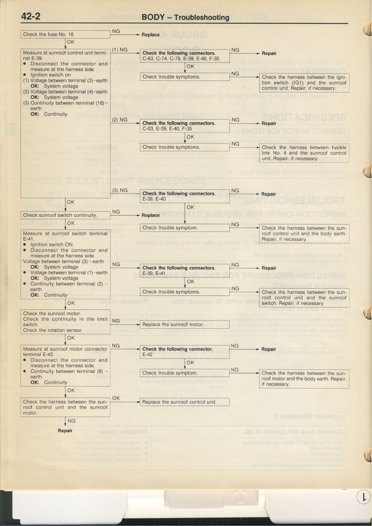
42-2
BODY - Troubleshooting
Check the fuse No. 18
Measure at
nal E-39.
.
o
(1
)
(2)
(3)
sunroof control unit termi-
Disconnect
measure
lgnition
Voltage between terminal
OK: System voltage
Voltage between terminal
OK: System
Continuity between terminal
earth
OK:
the connector and
at the harness side.
switch
on
voltage
Continuity
(3)-eadh
(4)-eadh
(18)-
(1)
(2)
NG
NG
Replace
the following
Check
c-63, C-74,
Check the following
c-03,
Check trouble symptoms.
Check
E-39, E-40
C-78,
E-39, E-40, F-35
the following
connectors.
E-39, E-40, F-35
connectors.
connectors.
Repair
Check the harness
tion switch
control unit. Repair, if necessary.
Repair
the harness
Check
link
No. 4 and
unit. Repair, if
Repair
between the
(lG1)
and the
between fusible
the sunroof control
necessary.
sunrooi
t'l)
igni-
,ll
sunroof
Check
Measure
tr-4t.
o
lgnition
.
Disconnect the connector and
measure at the harness
Voltage
OK: System voltage
.
Voltage between terminal
OK:
o
Continuity between terminal
earth
OK: Continuity
the sunroof motor.
Check
Check the continuity in the limit
switch.
Check the rotation sensor.
Measure at
terminal E-42.
.
Disconnect the
measure at the harness side.
.
Continuity
earth
OK: Continuity
switch continuitv
at sunroof switch terminal
switch ON
side.
between terminal
voltage
System
sunroof
between terminal
(3)-earth
(1)-earth
(2)
motor
connector
connector and
(8)
Replace
the harness
Check
roof
control unit and the
Repair,
if necessary.
Ctect fre tottowingcon'1ectqrs.
tr-:lq tr-41
-
OK
l-\q
+
Repair
Check the harness
roof control
switch. Repair, if necessary.
between the sun-
body earth.
between the sun-
unit and the sunroof
,,Jd
Reolace
-
the sunroof motor
the
Check
roof
motor and the
if
necessarv.
harness
between the
body earth. Repair,
sun-
Check
roof
control unit
molor.
the harness
Repair
between the sun-
and the
sunroof
Reolace
the sunroof control unit.
,c
Page 20
BODY
-
Service
Adjustment
procedures
42-3
=s
im
\ lL----Jl
l-
z-:-[=
Approx.
-<=
a\\\
r8AO216
18XO545
30
cm
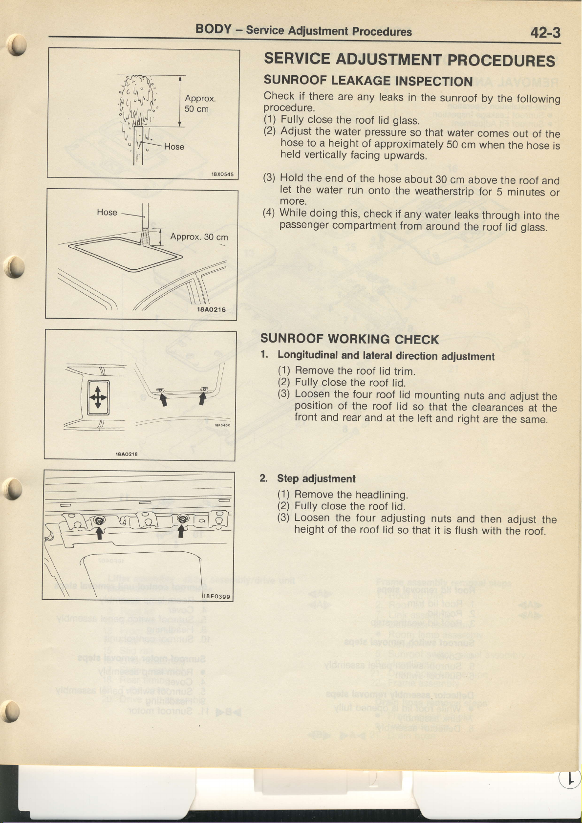
SERVICE
SUNROOF
check
procedure.
(1)
(2)
(3)
if
Fully
Adjust
hose
held
vertically
Hold
let
the
ADJUSTMENT
LEAKAGE
there
close
the
the
water
to
a height
the
end
water
more.
(4)
While
passenger
SUNROOF
1.
Longitudinal
(1)
(2)
(3)
doing
compartment
WORKING
Remove
Fully
close
Loosen
position
front
the
and
the roof
INSPECTION
are
any
leaks
roof
of approximately
facing
of
the hose
run
this,
check
glass.
lid
pressure
upwards.
onto the
if
from
CHECK
and lateral
the roof
four
of the roof
rear
and
direction
lid
trim.
tid.
roof
lid
at the
lid
PROCEDURES
in
the
sunroof
so
that
water
50
cm when
about
any
30
cm above
weatherstrip
water
leaks
around
adjustment
mounting
so
that
the
left
and right
by
the following
comes
the
the
for
5 minutes
through
the roof
nuts
clearances
and
are
lid
adjust
the
out
hose
roof
into
glass.
at
same.
of the
is
and
or
the
the
the
2.
Step
adjustment
(1)
Remove
(2)
Fully
(3)
Loosen
height
\
the headlining.
close
the roof
the four
of the roof
lid.
adjusting
lid
so that it
nuts
is flush
and
then
with
adjust
the roof.
the
Page 21
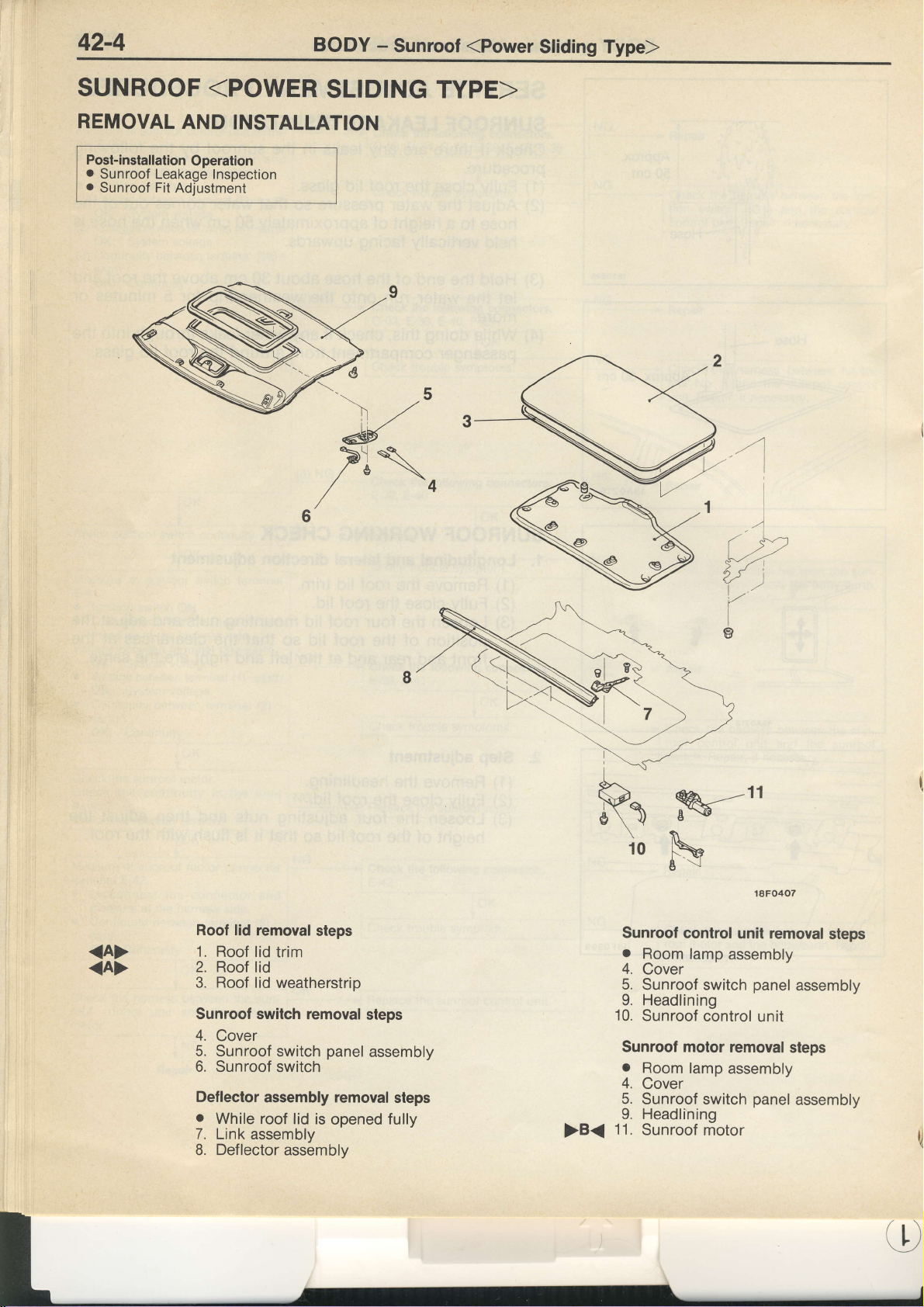
42-4
BODY
-
Sunroof
(Power
Sliding
Type)
SUNROOF
REMOVAL
Post-installation
o
Sunroof Leakage
o
Sunroof Fit Adjustment
<POWER
AND INSTALLATION
Operation
Inspection
SLIDING TYPE>
<A>
<A>
Roof lid
1.
2. Roof
3. Roof lid
Sunroof switch
4.
5. Sunroof
6. Sunroof
Deflector
o
7.
B.
removal
Roof lid
Cover
While roof
Link assembly
Deflector
trim
lid
weatherstrip
switch
switch
assembly removal
lid is
assembly
steps
removal
panel
opened
steps
assembly
steps
fully
>B<
M
N
Sunroof
.
4.
5.
9. Headlining
10.
Sunroof motor
o
4.
5.
9. Headlininq
'11.
control
Room
Cover
Sunroof switch
Sunroof
Room
Cover
Sunroof switch
Sunroof
lamp
c-ontrol
lamp
riotor
11
18F0407
unit removal
assembly
panel
assembly
unit
removal
assembly
steps
panel
assembly
steps
Page 22
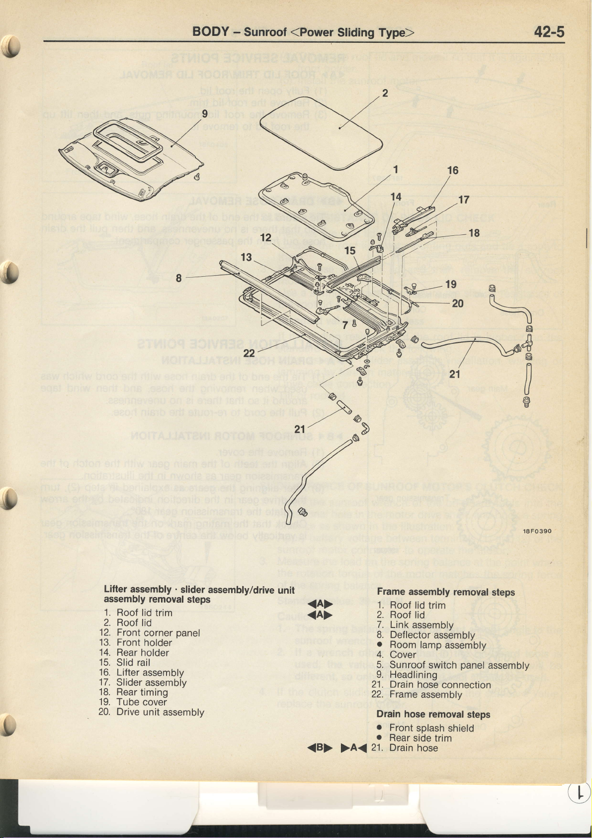
BODY
-
Sunroof
(Power
Sliding Type)
42-5
ip
v,.,
N--20
o#
/
,n
21
R
\
u
Lilter
assembly
assembly removal
'1.
Roof
lid
2. Roof lid
12. Front
13. Front
14.
Rear
15.
Slid rail
16. Lifter
17.
Slider
18. Rear
19. Tube
20.
Drive
trim
corner
holder
holder
assembly
assembly
timing
cover
unit
assembly
.
slider
steps
panel
assembly/drive
unit
<A>
<A>
<B>
>A<
Frame
1
I.
Roof
Roof
2.
Link
7.
Deflector
8.
a
Room
4.
Cover
Sunroof
9.
Headlining
21.
Drain hose
Frame
22.
Drain
o
Front
.
Rear
21.
Drain
assembly
lid
lid
assembly
lamp
assembly
hose removal
splash
side
removal
trim
assembly
assembly
switch
connection
shield
trim
hose
panel
steps
steps
assembly
Page 23
BODY
-
Sunroof
REMOVAL
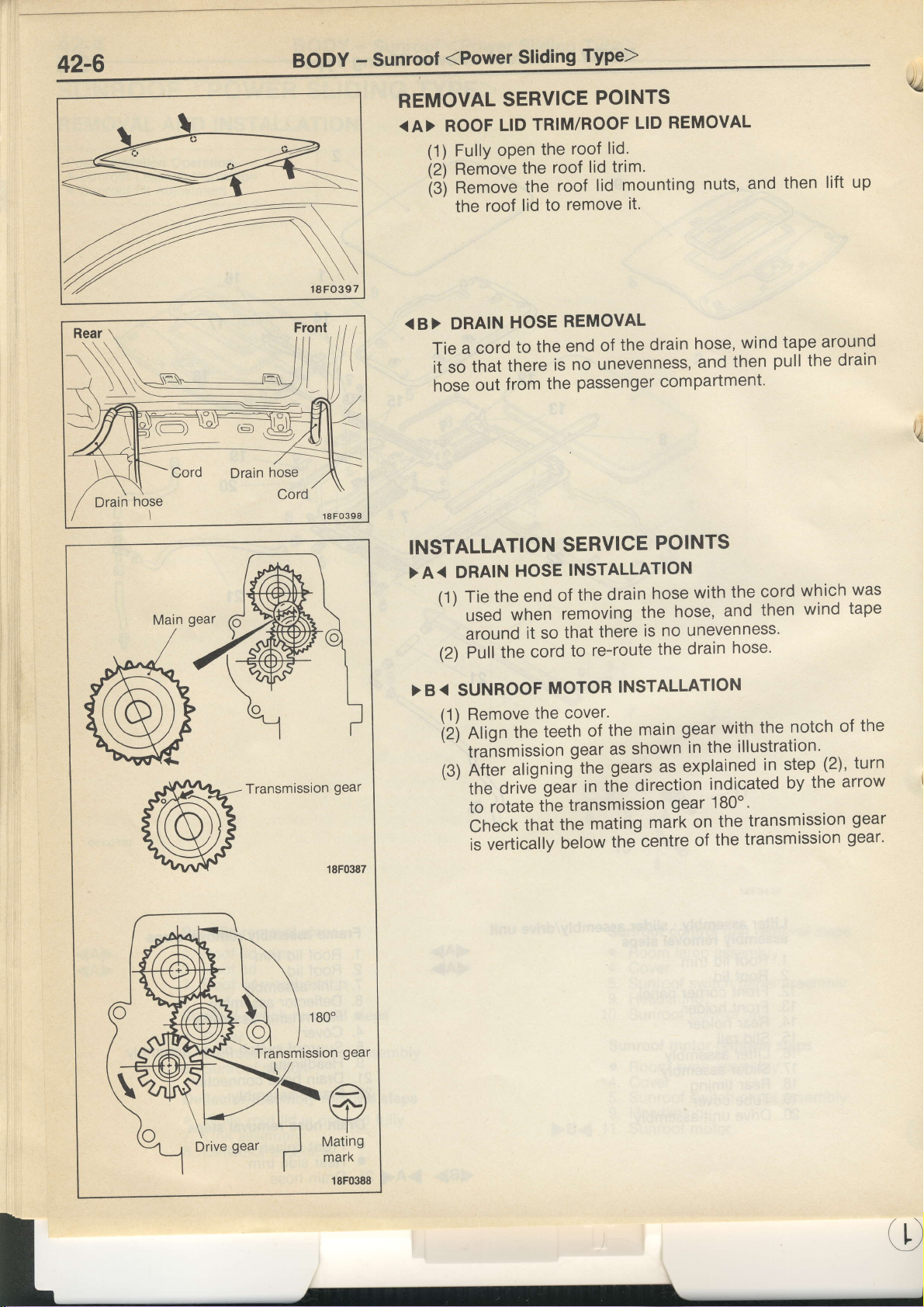
<A>
(Power
ROOF
(1)
Fully
(2',)
Remove
(3)
Remove
the
Sliding
SERVICE
TRIM/ROOF
LID
the
open
roof
the
roof
the
remove
to
lid
roof
Type)
POINTS
lid.
roof
trim.
lid
mounting
lid
REMOVAL
LID
it.
nuts,
and
then
lift
4,1,
up
Main
gear
Transmission
gear
REMOVAL
passenger compartment'
the
SERVICE
INSTALLATION
removing
there
that
so
it
re-route
to
cord
MOTOR
cover.
the
teeth
INSTALLATION
the
of
gear as
gears as.explained
geir
the
the
in
transmission
POINTS
hose,
the
no unevenness'
is
the
main
shown
direction
and
hose'
drain
gear with
the
in
indicated
gear 180o'
wind
then
notch
the
illustration'
(2)' turn
step
in
the
by
tape
the
of
arrow
out
HOSE
from
DRAIN
<B>
Tieacordtotheendofthedrainhose,windtapearound
itsothatthereisnounevenness,andthenpullthedrain
hose
INSTALLATION
>A<
DRAIN
(1)Tietheendofthedrainhosewiththecordwhichwas
'
used
HOSE
when
around
> B
(2)
<
(1)
iZi
'
the
Pull
SUNROOF
Remove
the
nf ign
'
traismission
(g)
aligningithe
Aiier
drivJ
the
rotate
to
Checkthatthematingmarkonthetransmissiongear
isvertical|ybe|owthecentreofthetransmissiongear.
q
Drive
gear
,4.
w
Mating
marK
18F0388
Page 24
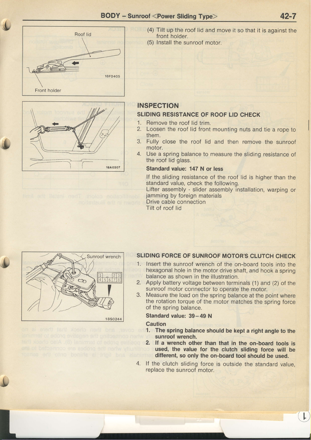
Front holder
Roof
lid
BODY
-
Sunroof
(Power
(4)
Tilt
front
(5)
lnstall
up the roof
holder.
INSPECTION
SLIDING RESISTANCE
1. Remove
2.
Loosen
them.
3. Fully
motor.
4.
Use a
the roof lid
Standard value: 147
lf
the sliding
standard
Lifter
jamming
Drive
Tilt
the roof lid
the roof
close the roof lid
spring
value,
assembly
by foreign
cable connection
of roof lid
Sliding Type)
lid
and move it
the
sunroof motor.
ROOF
OF
trim.
lid front mounting
balance to
glass.
resistance
check the following.
.
slider
measure
N
or
of the roof lid is
assembly installation,
materials
so that it is
LID CHECK
nuts
and
and then remove
the
sliding resistance
less
higher
42-7
against
tie a rope
the
warping
the
sunroof
than the
io
of
or
SLIDING FORCE
1.
Insert
hexagonal
balance
2.
Apply
sunroof
3. Measure
the rotation
of the
Standard
Gaution
1.
2.
4.
lf
replace
the
sunroof wrench
hole
as
shown in
battery voltage
motor
the load
torque
spring
value:
The
spring
sunroof
lf
used, the
different,
the
wrench.
a wrench
clutch
the
sunroof motor.
balance.
so
sliding force
OF SUNROOF MOTOR'S
of the on-board
in the motor
the illustration.
between terminals
connector to
on the spring
the
of
39-49
balance
other
value
for the
only the
drive
shaft, and hook
operate the motor.
balance
motor matches
N
should
than that
be kept
in the
clutch
on-board
is
outside the
CLUTCH
at the
a right
on-board
sliding force
tool
should be
CHECK
tools into
(1)
and
point
the spring force
angle to
standard
the
a spring
(2)
the
of
where
the
tools is
will
be
used.
value,
Page 25
42-8
BODY
-
Sunroof
(Power
Sliding
Type)
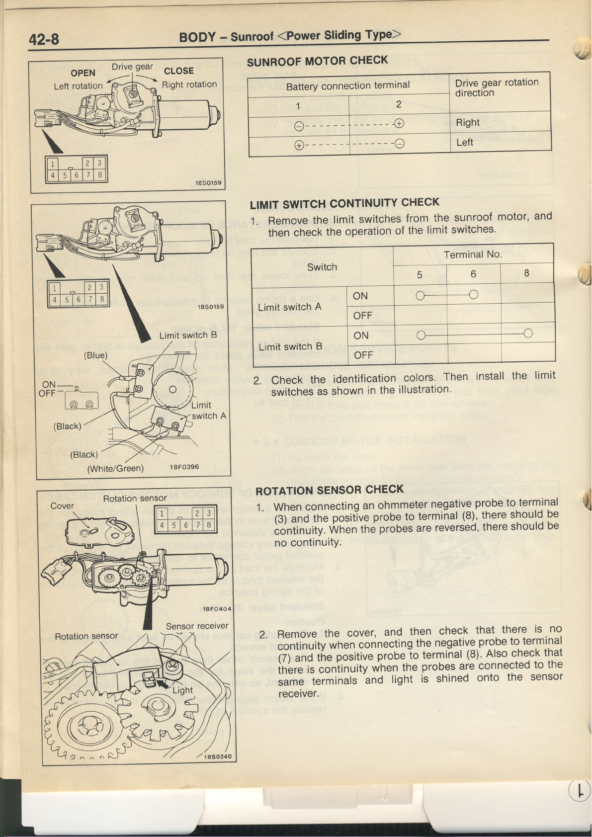
Drive
-ffi
gear
CLOSE
Right
switch
Limit
rotation
B
SUNROOF
LIMIT
MOTOR
Battery
SWITCH
CHECK
connection
termi
CONTINUITY
nal
CHECK
gear rotation
Drive
direction
l.Removethelimitswitchesfromthesunroofmotor'and
switches'
limit
the
then
Limit
check
switch
the
A
operation
of
Terminal
No.
,d
oN-^
OrF-[+__1
t@
(Black)
(Black)
@l
(White/Green)
Rotation
sensor
1
8FO396
2'ChecktheidentificationcoIors.Theninsta||theIimit
shown
switches
ROTATION
as
SENSOR
in the
CHECK
l.Whenconnectinganohmmeternegativeprobetotermina|
posiiive
and
the
when
the
(3)
iontinuity.
illustration'
probe
terminal
to
probes are
(8), there
reversed,
there
should
should
be
be
ui
no cclntinuitY.
no
terminal
to
sensor
the
is
to
the
there
Remove
2.
continuity
cover,
the
when
then
and
connecting
the
check
ne.gative
that
probe
(7)andthepositiveprobe-totermina|(8).A|socheckthat
inbre
same
is coniinuity
terminals
when
and
the
light
probes are
shined
is
connected
onto
receiver.
Page 26

'(,
BODY
-
Sunroof
SUNROOF
(Power
SWITCH
Sliding
CONTINUITY
Type)
42-9
CHECK
Open
OFF
Close
Switch
position
1
o_
Terminal
2
--{
G-
No.
3
----c
v
Page 27

54-1
cHASSls ELECTRIGAL
-
General/speciat
root/Troubleshooting
,4g,)
GENERAL
OUTLINE
o
An immobilizer
equipment in vehicles
IGNITION
OF CHANGE
system has
SWITCH AND
SPECIAL TOOL
Tool
GROUP
54
CHASSIS ELECTRICAL
been
for Australia.
Number
M8991502
provided
IMMOBILIZER
Name
MUT-II
assembly
as
sub
an
option in vehicles
SYSTEM
Use
for
Checking the
(diagnosis
Registering
sysrem
display using
lD
Europe,
immobilizer
codes for the immobilizer
and
as
standard
system
the MUT-II)
lra
TROUBLESHOOTING
STANDARD FLOW
Gathering information
Check diagnosis
(Refer
No diagnosis
can't
communicate
code or
OF DIAGNOSTIC
from
customer
to P.54-2.1
code
TROUBLESHOOTING
Verify
complaint
Diagnosis
displayed
Recheck
(Reler
Check trouble
(Refer
diagnosis
to
P.54-2.)
to P.54-2.)
code
code(s) then
codes
Diaonosis
Does not
Check diagnosis
(Refer
to P.54-2.)
erase
code
reoccur
code
No
diagnosis
code
,rl)
Inspection
(Refer
to P.54-2.)
chart for trouble
symptoms
Inspection
(Refer
to P.54-2.)
chart for
diagnosis
codes
t/l
Page 28

CHASSIS
ELECTRICAL
-
Troubteshooring
54-2
INSPECTION
Diagnosis
NOTE
*
:
Diagnosis
CHART
code No.
'11
12*
21
31
32
code
No.
FOR
DIAGNOSIS
Transponder
lD
codes
are
Communication
EEPROM
12
is not
lgnition
switch
recorded.
DIAGNOSIS
DIAGNOSIS
Connect
the lower
codes.
ERASING
Connect
erase
Caution
The
the
TROUBLE
communication
not
the
same
system
abnormality
lG
inside
signal
FUNCTION
CODES
the
MUT-II
of the
DIAGNOSIS
the MUT-II
the
diagnosis
diagnosis
battery
CODES
Inspection
system
or
are not
between
immobilizer-ECU
circuit
trouble
cables
items
registered
MUT-II
system
CHECK
to
the
instrument
under
CODES
to
the
diagnosis
codes.
codes
cannot
and
be
engine-ECU
diagnosis
connector (16-pin)
cover,
connector (16-pin)
which
result
erased.
then
check
from
Reference
at
diagnosis
then
disconnecting
page
54-3
54-3
54-4
54-4
54-5
Page 29

54-3
CHASSIS
ELECTRICAL
-
lgnition Switch
lmmobilizer
and
System
INSPECTION
Gode
The lD code of
after
Does
ignition
code
lgnition
check
No.
the ignition
the engine start
key which
registered?
key ring
(Refer
PROCEDURE
11 Transponder
the transponder
switch
has had the
NG
Code
antenna continuity
P.54-10.)
to
is
using
No.
is not
turned
the spare
generated
11
FOR DIAGNOSIS
communication
immobilizer-ECU
to the
sent
code
NG
position.
12
No.
generated
To inspection
code
Check
bilizer-ECU
antenna.
to the ON
lD
TROUBLE GODES
system
immediately
procedure
(Refer
No. 12
the harness between
and the
for
P.54-3.)
to
ignition key
Probable
o
.
.
o
diagnosis
immo-
the
ring
cause
Malfunction of
Mallunction
Malfunction
Malfunction of
of
of
transponder
key ring
ignition
harness or
immobilizer-ECU
Re-register
(Reler
to
antenna
connector
the lD code.
P.54-11.)
ud)
No. 12
Code
registered
The lD code
is registered
which
Re-register
(Refer
the
to P.54-1
lD codes
is
which
lD code.
1.)
from the
sent
in the immobilizer-ECU.
Reolace the
not
are
the same
transponder is not the same
or are
immobilizer-ECU.
not
lD
as the
code
Probable
o
The lD code
properly
been
.
Malfunction of
cause
in the ignition
registered"
immobilizer-ECU
key being used
has not
ui
Page 30

cHAssls
ELECTRIGAL
-
tgnition
switch
and rmmobitizer
system
54-4
c
Code No.21
engine-EGU
After
the ignition
received
received.
ls
erated
Check the
c-21.
from
diagnosis
by the
following
C-44. C-90
the
code
engine-ECUt
Communication
switch
is turned
engine-ECU within
No.
54
connectors.
being
to the
the
gen-
system
position,
ON
allowable
between
the confirmation
time, or an
Engine-ECU
circuit
Check the harness
ECU
MUT-II
code is nol
abnormal
power
(Refer
check
and the immobilizer-ECU.
between the engine
and
is
code
circuit and
to
GROUP 13-
Probable
o
Malfunction
a
Malfunction
a
Malf
unction
earth
cause
of harness
of engine-ECL
of immobilizer-ECU
or connector
s
Code No.31
No
data
has been written
CtrecX trouble
l
EEPROM
symptoms.
abnormality inside
to the EEPROM
inside
immobilizer-EGu
the immobilizer-EOU. o
Probable
Malfunction
cause
of immobilizer-EOU
b
Page 31

54-5
Code
ignition
The
No.32
switch
GHASSIS
lgnition
signal
switch
not being
is
ELECTRICAL
lG signal
input
circuit
the immobilizer-EOU'
to
-
lgnition
system
Switch
Probable
a
a
a
lmmobili4lty$g.
and
cause
Malfunction
Malfunction
Malf unction
of
of
of
connector
harness
ignition
immobilizer-ECU
or
switch
@
switch
conneclors.
between
fuses
and
(lG1) and the
im-
switch
lgnition
Measure
tor C-90.
o
Disconnect
measure
.
Voltage
OK:
immobilizer-ECU
at
earth
body
(lgnition switch:
System
lG signal
the connector
harness
at the
between
terminal
ON
voltage
input check
connec-
and
side.
(2)
Position)
and
Check
c-76.
Check
the
mobilizer-ECU.
c-78,
harness
the
ignition
C-90
following
the
Irr!)
TROUBLE
INSPECTION
Communication
Diagnosis
lD code
l
l
Engine
lmmobilizer-ECU
CHART
code
cannot
not start
does
with
No. 54
be
FOR
Trouble
MUT-II
the
been
has
registered
(turns
power
circuit
symptom
is
generated
using
but
over
and
SYMPTOMS
possible
not
by
MUT-II
the
not
does
circuit
earth
engine-ECU
the
ignite)
check
Inspection
procedure No.
I
I
2
e
4
5
Reference
54-6
54-7
54-7
54-8
54-9
page
@l
q
Page 32
,s
cHAsSls
INSPECTION
Inspection
PROCEDURE
Procedure
ELECTRIGAL
FOR
TROUBLE
1
-
tgnition
switch
SYMPTOMS
and tmmobitizer
system
54-6
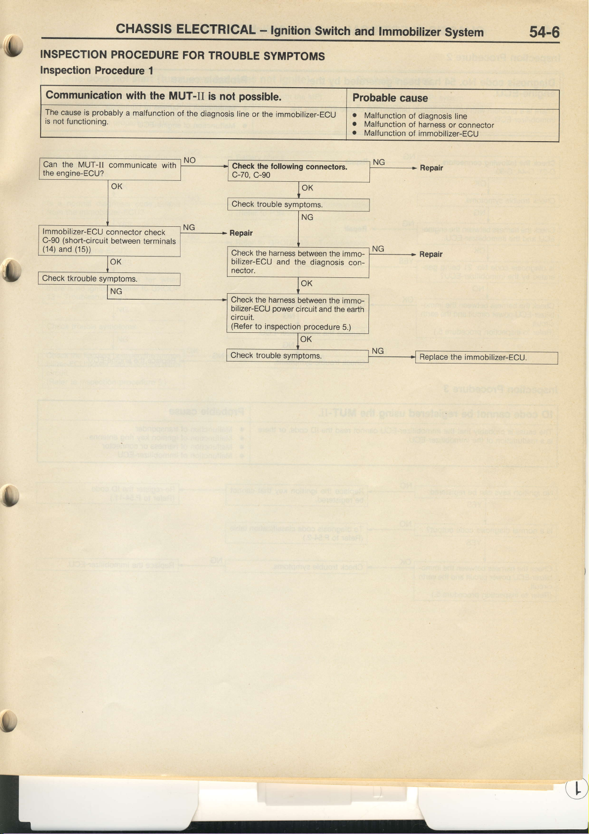
Communication
The
cause is
is not
Can
the
engine-ECU?
lmmobilizer-ECU
C-90
(14)
and
probably
functioning.
the MUT-II
(short-circuit
(15))
connector
communicate
between
with
the MUT-II
a malfunction
with
check
terminals
is not
of
the diagnosis
possible.
line
or the immobilizer-ECU
Check the following
c-70,
c-90
Check the harness
bilizer-ECU
nector.
Check the harness
bilizer-ECU
circuit.
(Refer
and
the
power
to inspection
connectors.
between
diagnosis
between
circuit and
procedure
Probable
o
.
.
the immo-
con-
the immo-
the
earth
5.)
cause
Malfunction
Malfunction
Malfunction
of diagnosis
of harness
of immobilizer-ECU
Replace
line
or connector
the
immobilizer-EOU.
Page 33
54-7
cHAssls
ELECTRIGAL
-
tgnition
switch
and tmmobitizer
system
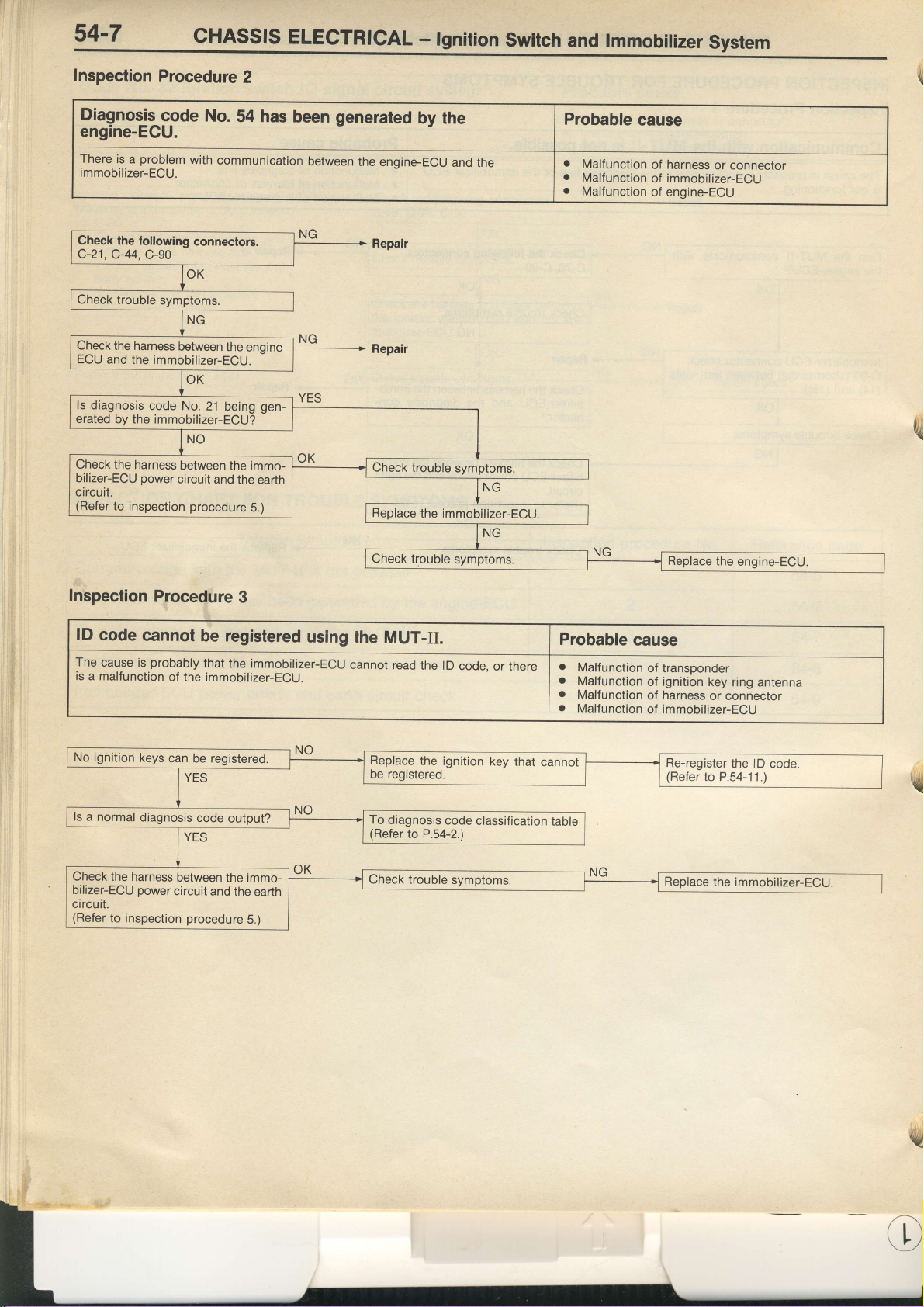
Inspection
Diagnosis
Procedure
code
engine-ECU.
There
immobilizer-ECU.
Check
c-21.
Check
ECU
ls
diagnosis
erated
Check
bilizer-EOU
circuit.
(Refer
problem
is a
the following
C-44.
C-90
the harness
and
the immobilizer-ECU.
code No.
by the immobilizer-ECU?
the harness
power
to inspection
No.
with
communication
connectors.
between
21
between
circuit
and
procedure
2
54 has
the
enoine.
gen-
being
the immo-
the
earth
5.)
been
between
generated
the engine-ECU
by the
Replace
and
the
the immobilizer-ECU.
Probable
a
Malfunction
a
Malf
unction
a
Malfunction
cause
of harness
of immobilizer-ECU
of engine-ECU
or connector
u,
Inspection
lD
code
The
cause
is a malfunction
No ignition
ls
a normal
Check
bilizer-ECU
circuit.
(Refer
Procedure
cannot
probably
is
keys
diagnosis
the harness
power
to inspection
3
be registered
that the immobilizer-ECu
of
the immobilizer-ECU.
can
be registered.
code output?
between
circuit
the immo-
and the
procedure
earth
5.)
using
cannot
the
MUT-II
read
Replace
be registered.
To
diagnosis
(Refer
to
the lD
code,
the ignition
code
P.54-2.)
classification
or there
key
that
Probable
.
Malfunction
.
Malfunction
.
Malfunction
.
Malfunction
cannot
table
Replace
cause
of transponder
of ignition key
harness
of
immobilizer-ECU
of
Re-register
(Refer
the
engine-ECU.
ring
or connector
to P.54-11.)
antenna
the lD
code.
't{
w
Page 34
CHASSIS
ELECTRICAL - lgnition
Switch
and lmmobilizer
System 54-8
o,
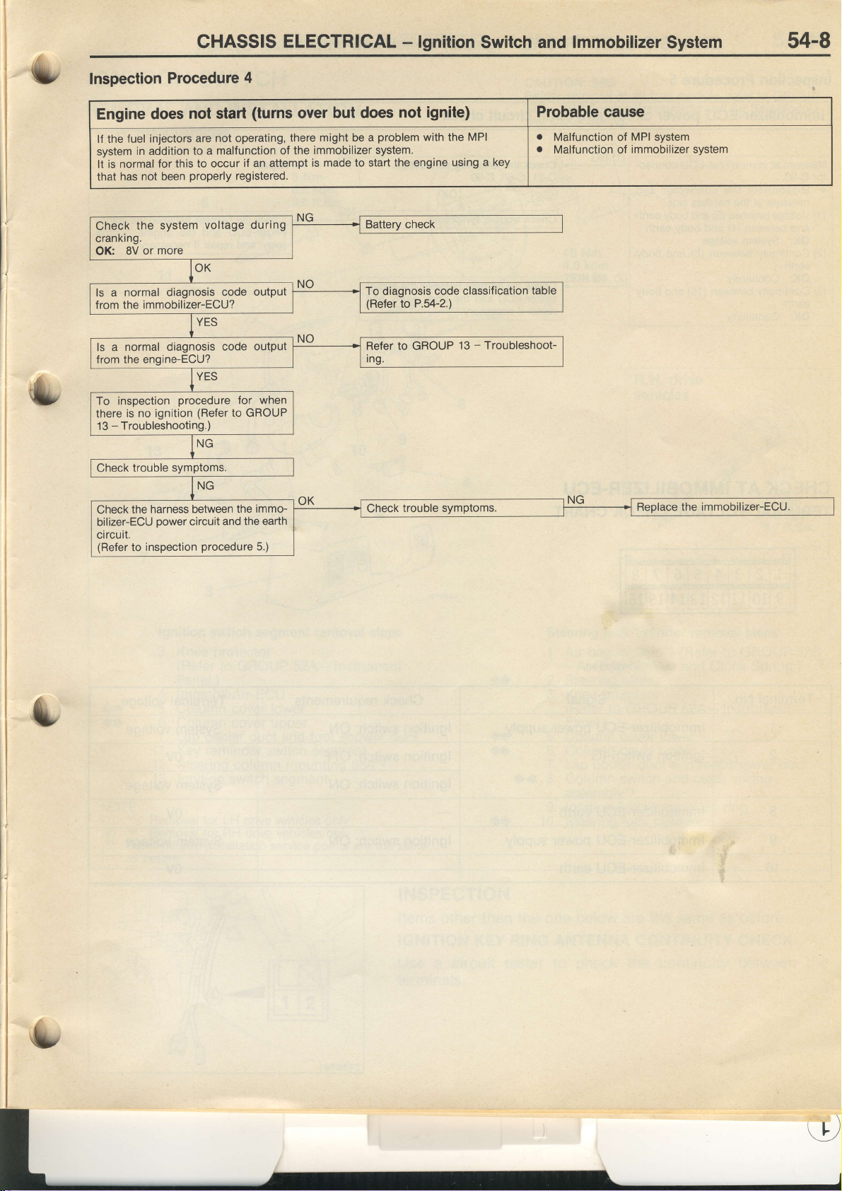
Inspection
Procedure
Engine does
fuel injectors
lf the
in addition
system
is normal
It
that
Check
cranking.
OK:
a normal diagnosis
ls
f rom the
ls a normal
from
To inspection
there
-
13
for this
has not been
the system
more
8V or
immobilizer-ECU?
the engine-ECU?
Troubleshooting.)
diagnosis
is no ignition
4
not start
are not operating,
to a malfunction
to
properly
procedure
(Refer
if an attempt
occur
registered.
voltage during
code
code output
for
to GROUP
(turns
there
of the
output
when
but does
over
might be a
immobilizer system.
is made to start the engine
not ignite)
problem
To
diagnosis
(Refer
to
Reter
Ing.
to P.54-2.)
GROUP
with the
MPI
key
using a
code classification
13 - Troubleshoot-
Probable
o
Malfunction of
.
Malfunction of
table
cause
MPI system
immobilizer system
harness between
the
Check
bilizer-ECU oower
circuit.
(Refer
to inspection
and the earth
circuit
procedure
the immo-
5.)
Page 35
54-9
CHASSIS
ELECTRICAL
-
lgnition
Switch
lmmobilizer
and
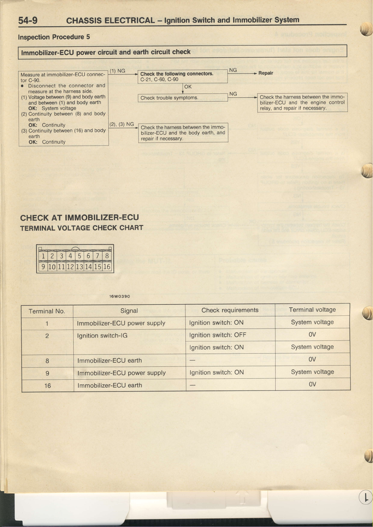
Inspection
Procedure
lmmobilizer-EGU
Measure at
tor C-90.
o
(1)
(2)
(3)
CHECK
TERMINAL
immobilizer-ECU
Disconnect
measure at
Voltage between
and between
OK:
Continuity
earth
OK:
Continuity
earth
OK:
the
the harness
(1)
voltage
System
between
Continuity
between
Continuity
AT
VOLTAGE
connector
(9)
and body
and
IMMOBILIZER.ECU
5
power
connec-
side.
earth
bodY
(8)
and body
(16)
and body
circuit
and
earth
CHECK
and earth
Check
c-21.
Check
bilizer-ECU
repair
CHART
circuit
check
following
the
c-90
c-60,
harness between
the
and the body
if necessary.
connectors.
the immo-
earth,
and
the harness between
Check
bilizer-ECU
relay, and
and
repair if necessary.
the engine
the
immo-
control
r 'i
tryU
Terminal
No.
I lmmobilizer-ECU
2
B
9
16
lgnition switch-lG
lmmobilizer-ECU
lmmobilizer-ECU
lmmobilizer-ECU
16WO390
Signal
power
earth
power
earth
supply
supply
Check
requirements
lgnition switch: ON
lgnition
switch: OFF
lonition switch: ON
lgnition switch:
ON
Terminal
System
voltage
OV
System
voltage
OV
System
voltage
OV
voltage
rcj
Page 36
CHASSIS ELECTRICAL
-
lgnition
Switch
54-10
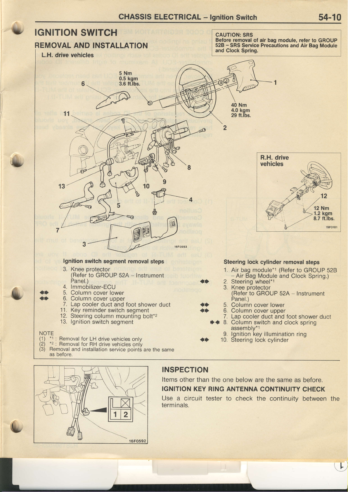
IGNITION
REMOVAL
L.H.
drive
SWITCH
AND INSTALLATION
vehicles
CAUTION:
Before
528
and
SRS
removal
-
SRS Service Precautions
Clock Spring.
of air bag module, refer
to
and Air Bag Module
GROUP
tf
{)
NOTE
-t
(1)
(?)
lr:
(3)
Removal
as before.
lgnition
3. Knee
switch
protector
(Refer
to
Panel.)
4.
lmmobilizer-ECU
5. Column
6. Column
7.
Lap
1].
12.
13.
: Removal
Removal
cooler
Key
reminder
Steering
lgnition
for
LH
for RH
and installation
segment removal
GROUP
52A - lnstrument
cover lower
cover
upper
duct and foot
switch
column
segment
mounting
switch segment
drive vehicles
drive vehicles
service
only
only
point5
steps
shower duct
bolt.z
are the same
INSPECTION
Items
IGNITION
Use a circuit
terminals.
Steering
1. Air
-
2.
Steering
Knee
3.
(Refer
Panel.)
{} 5.
{f
f{
Colunin
Column
6.
Lap
7.
Column switch
8.
assembly*1
lgnition
9.
10.
{}
other than
the one
Steering lock
KEY RING ANTENNA
tester to
lock
cylinder removal
bag module*1
Air Bag
Module and
wheel*1
protector
to
GROUP 52A - Instrument
cover
(Refer
lower
cover upper
cooler duct and foot
and clock
key illumination ring
cylinder
below
are the
same as
CONTINUITY
check
the
continuity
steps
to
GROUP
Clock
Spring.)
shower
spring
before.
CHECK
between the
528
duct
(.'
Page 37
54-11
CHASSIS ELECTRICAL
-
lgnition
Switch
ID
CODE
lf
using
if
the
register
immobilizer-ECU.
can
Moreover, when the
will need to use the
user
instruction manual
Caution
Because registering of
previously-registered
have ready all of the
registered.
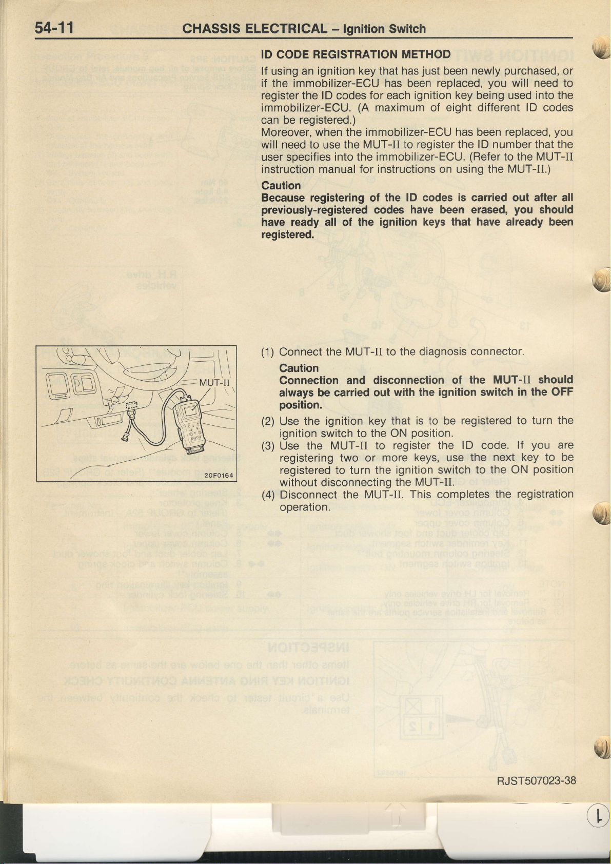
(1)
Connect
Caution
Connection and disconnection
always be carried
position.
(2)
Use
ignition switch
(3)
Use the
registering two or
registered to turn
without disconnecting
(4)
Disconnect
operation.
REGISTRATION
an ignition key that has
immobilizer-ECU has been
lD
the
registered.)
be
specifies into the
the ignition
codes
the
MUT-II to
for each
(A
immobilizer-ECU has
MUT-II
for instructions on using the MUT-II.)
MUT-II to the diagnosis connector.
key that is to be
to the ON
the MUT-II.
METHOD
ignition key
maximum
register the lD number that the
to
immobilizer-ECU.
the lD codes
codes
ignition keys that
out
the ignition switch
have been
with the
position.
register the
more
keys,
MUT-IL
the
This completes
just
replaced,
of eight different
ignition
newly
been
(Refer
is
carried out after all
erased,
the
of
registered to turn
lD
the
use
purchased,
you
being used
replaced,
been
to the
have
already been
MUT-II should
switch
code.
next
to the
the
or
will need to
into
the
lD
codes
you
MUT-II
you
should
in the
lf
ON
registration
OFF
you
key
to be
position
the
are
'!&t
RJ5T507023-38
Page 38
Pub. No.
ENGLISH
EUROPE
PWUE9I l9-E
Pub, No.
AND EXPORT
PWUE9203-4
tdl
A ursuBrsHr MoToRs
coRPoRATroN
July
1995 Printcd in Japan
1)
 Loading...