

Page 1
Volume 2
Electrical
: ~*.. $c :
._-.
~.~~
~l.1
-.-~-
&?&a-&&
-
Page 2

Page 3
GROUP / SECTION INDEX
MOOAAA- -B
1
L.J
BackupService
3OOOG-r
1991: Volume
FOREWORD
This Service Manual has been prepared
latest service information available at the time of
publication. It is subdivided into various group
categories
disassembly,
along
with
references. Use of this manual
performing
i
restore
designed
and each section contains diagnosis,
repair, and installation procedures
complete specifications and tightening
any servicing necessary to maintain or
the
high levels of performance
into these outstanding vehicles.
Manual
with
will
aid in properly
and
reliability
2
the
General
Fusible Link and Fuse Location
Inspection Terminal Location
Grounding
Diode Location
Junction
Centralized Junction
Inspection of Harness Connector
How to Diagnose
Configuration Diagram
Circuit Diagrams
Engine Electrical
. . . . . . . . . . . . . . . . . . . . .
Location
Block
. . . . . . . . . . . . . . . . . . . . . . . . . . . . . . . . . . . . . . . . . . . . . . . . . . . .
. . . . . . . . . . . . . . . . . . . . . . . . . . . . . . .
. . . . . .
.._................_...____.._.._._.......
. . . . . . . . . . . . . . . . . .
............................................
....................................
................................................
..................................
.._......._..._..__.._.......
. . . . . . . . . . . . .
. . . . . . . . . . . . . . . . .
.._....
.._....
..__._...
II
.._...................
................
m
q
a
Chassis Electrical
WE SUPPORT
VOLUNTARY
CERTIFICATION
AUKi~V~~VE
EXCELLENCE
Mitsubishi
design or
imposing any obligations upon itself
previously
c
@ 1990 Mitsubishi Motors Corporation
Motors
to
Corporation reserves
make additions
manufactured.
TECHNiClAN
THROUGH
National ln*titutefor
the
right
to or improvements in
to
install
to make
them on
its products
its products
Rap&ted
changes in
without
in USA
..................................
Page 4
2
GENERAL - Fusible Link and Fuse Location
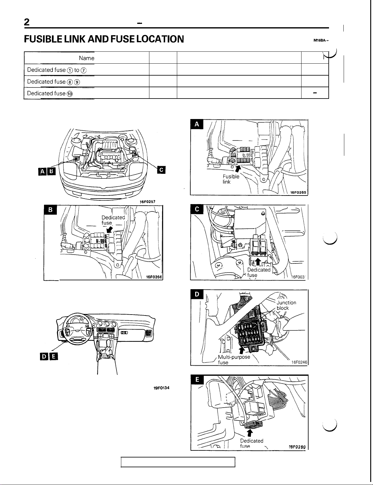
FUSIBLE LINK AND FUSE LOCATION
Symbol
Name
Symbo
M16BA-
/
-
B
C
E
NOTE
The “Name” column is arranged in alphabetical order.
<Engine compartment>
16FO257
Fusible link
Multi-purpose fuse
A
D
-
<Interior>
\ / fl
\\ 16FO266
19FO134
16FO260
TSB Revision
Page 5
GENERAL -
lrispection
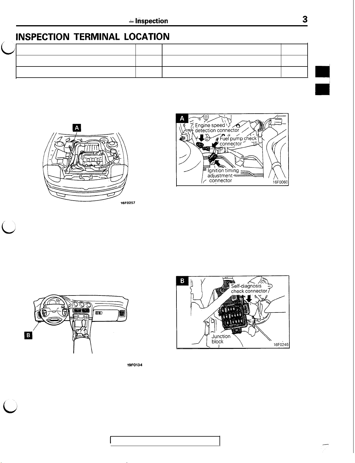
INSPECTION TERMINAL LOCATION
Terminal Location
3
c
Engine speed detection connector
Fuel pump check connector
NOTE
The “Name” column is arranged in alphabetical order.
Name
<Engine compartment>
ca
Symbol
A
A
Name
Ignition timing adjustment connector
Self-diagnosis check connector
/f co?nector
----,
;e;ooso
II
Symbol
A
B
‘J
c
<Interior>
19FO134
1
TSB Revision
Page 6
4
GENERAL - Groundina Location
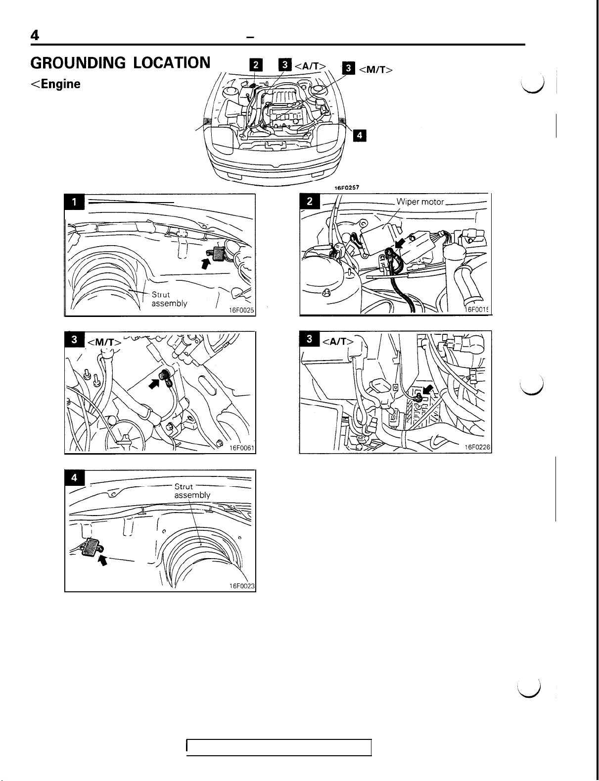
GROUNDING LOCATION
<Engiine
compartment>
a
1
TSB Revision
Page 7
c
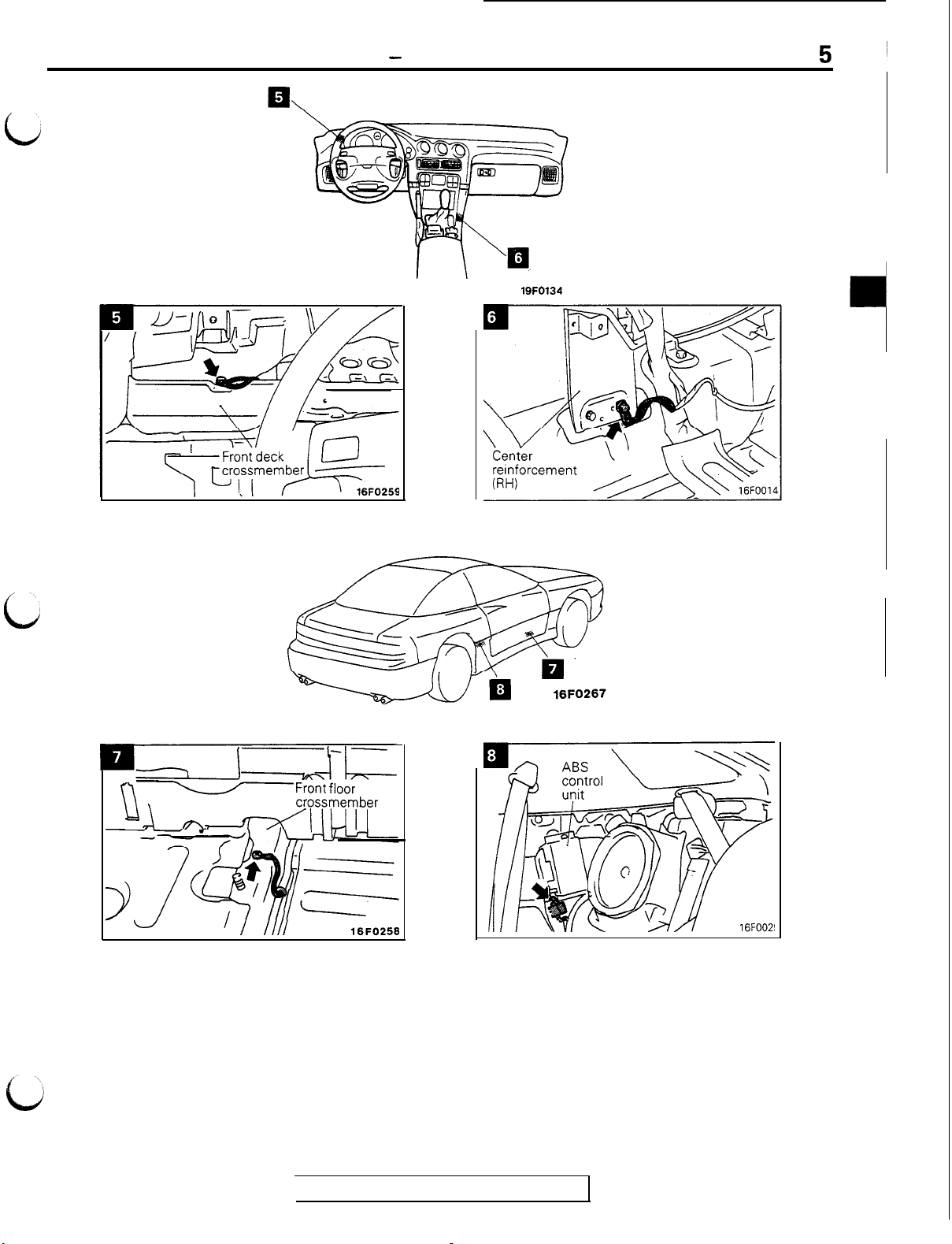
GENERAL - Grounding Location
<Interior>
19FO134
c
RZLJI-L
r‘\v
\\ \
“d n> dIIuII
r
d
Front
floor
crossmember
16FO256
TSB Revision
Page 8
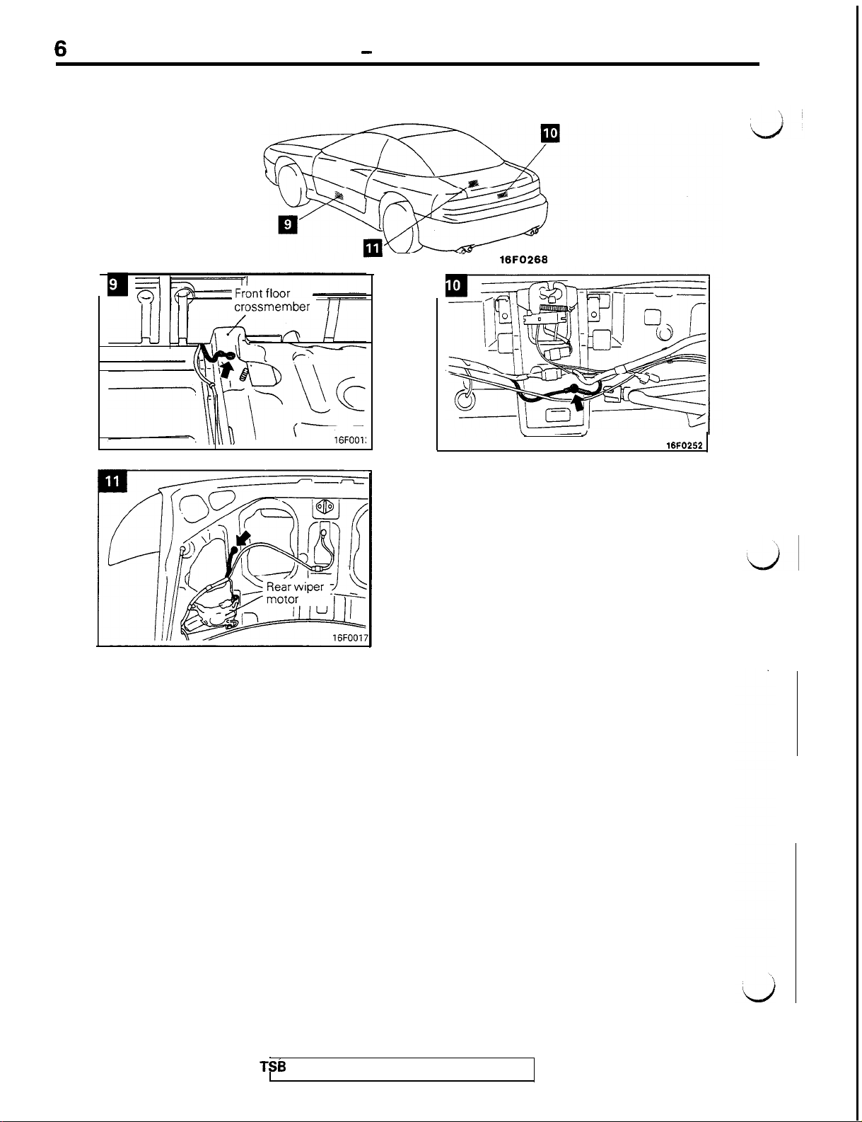
6
GENERAL - Grounding Location
16FO268
crossmember
,
16FO252
TSb
Revision
Page 9
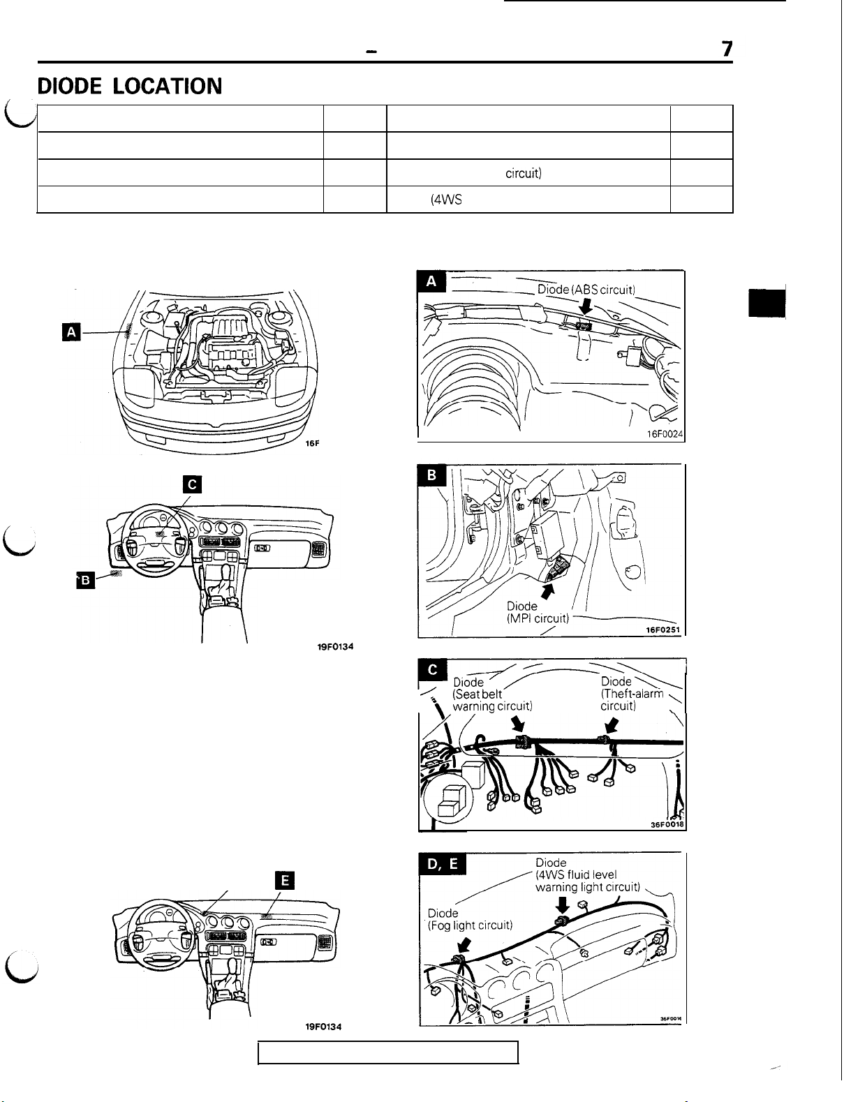
DIODE LOCATION
GENERAL
-
Diode Location
Name
Diode (ABS circuit)
Diode (Fog light circuit)
Diode (MPI circuit)
<Engine compartment>
<Dash panel>
Symbol
0257
Name
A
D
B
Diode (Seat belt warning circuit)
Diode (Theft-alarm
Diode
(4WS
fluid level warning light circuit)
I
circuit)
-
Diode (ABS circuit)
Symbol
C
C
E
16FOO2L
c
<Instrument panel>
q
R
19FO134
<
(Seat belt
\
warning circuit)
)ioZ ’
Diode \\
(Theft-alarm ,
circuit)
36FOO18
,
,-.
19FO134
TSB Revision
Page 10
8
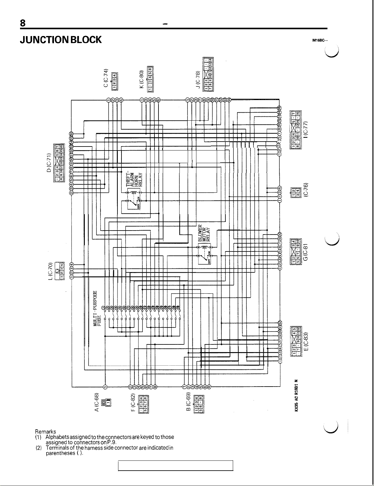
JUNlCTION BLOCK
GENERAL - Junction Block
I I , I I
I I I I I
lI+-4--wlI-
I I I
I 1 I
I I!1
4-l-J I I I I I I 4r-43
’ iIII/IlI
I I
dIllIll
m
cu
E!
NV
-0
E
k
-
E
ii
I
6
0
u
Remarks
(1)
Alphabets
assigned to connectors on P.9.
(2)
Terminals of the harness side connector are indicated in
parentheses ( ).
assigned to
the connectors
TSB Revision
are keyed
to those
E
ii
Lu
z
6
E
P
B
::
Page 11
GENERAL
- Junction Block
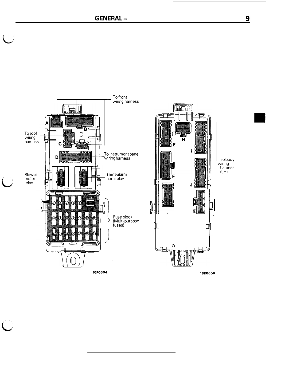
To roof
wiring
harness
Blowe
motor
relay
Front
To front
- wiring harness
To instrument panel
-wiring harness
Theft-alarm
horn relay
Back
To body
wiring
harness
(LH)
G
Fuse block
(Multi-purpose
fuses)
i
h
0
uu
\1
/
16FO304
~tfb#J”
oe.Jl
d
i
LYJ
16FOO56
TSB Revision
Page 12
GENERAL - Centralized Junction
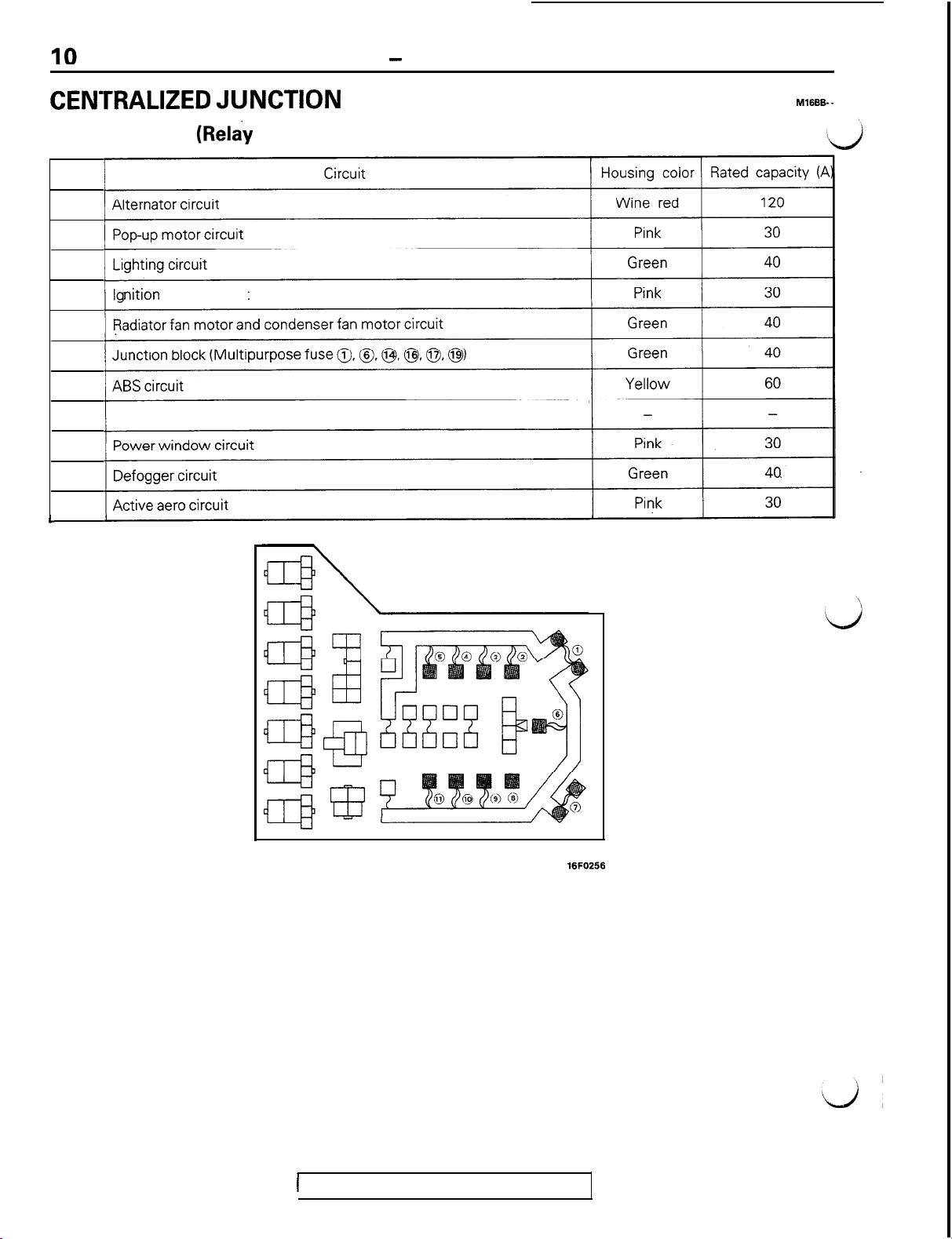
CENTRALIZED JUNCTION
FUSIBLE LINK (Relay box in engine compartment)
No.
1
2
3
nition
4
5
6
7
8
9
IO
11
L
switch circuit
1
TSB Revision
Page 13
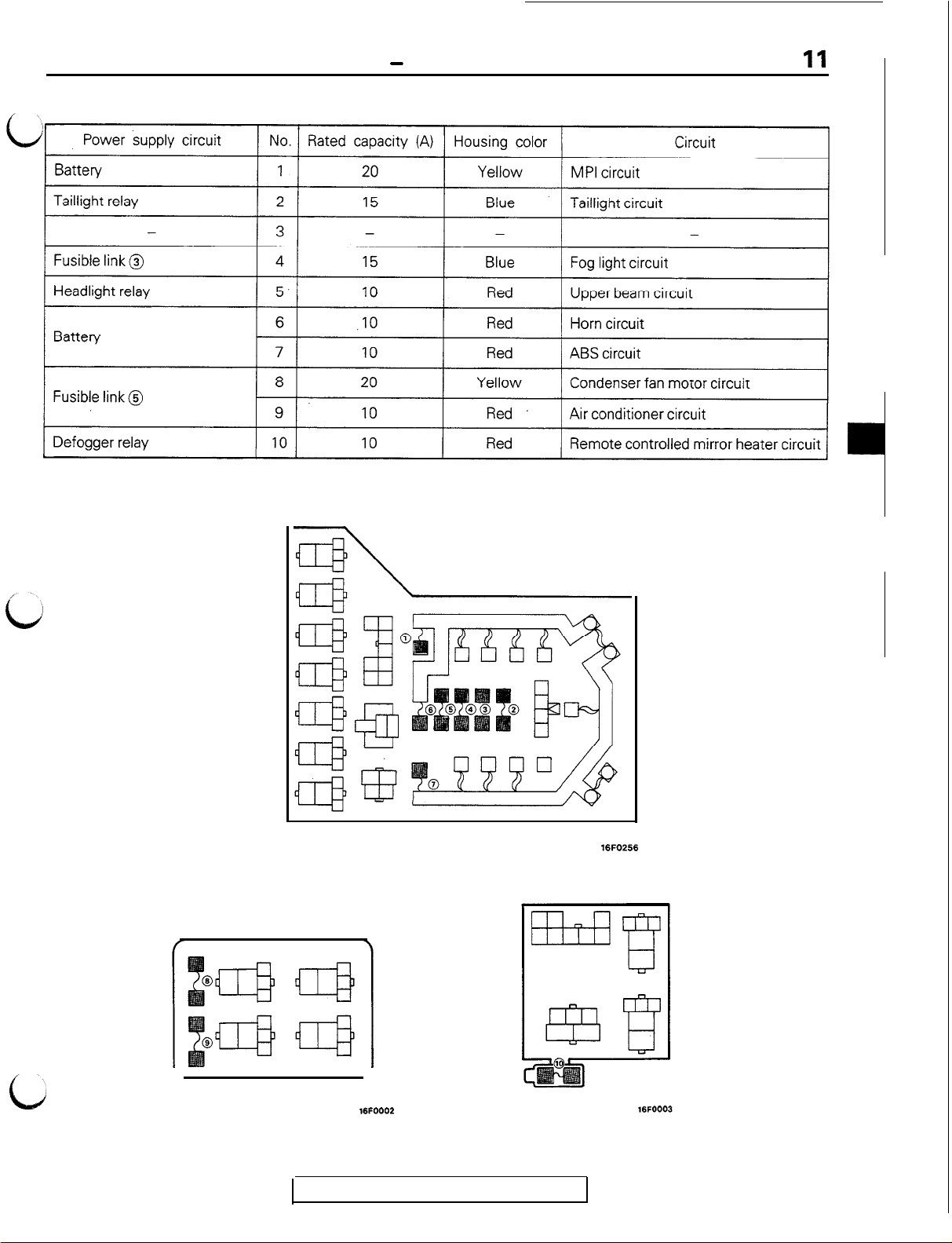
DEDICATED FUSE
GENERAL
-
Centralized Junction
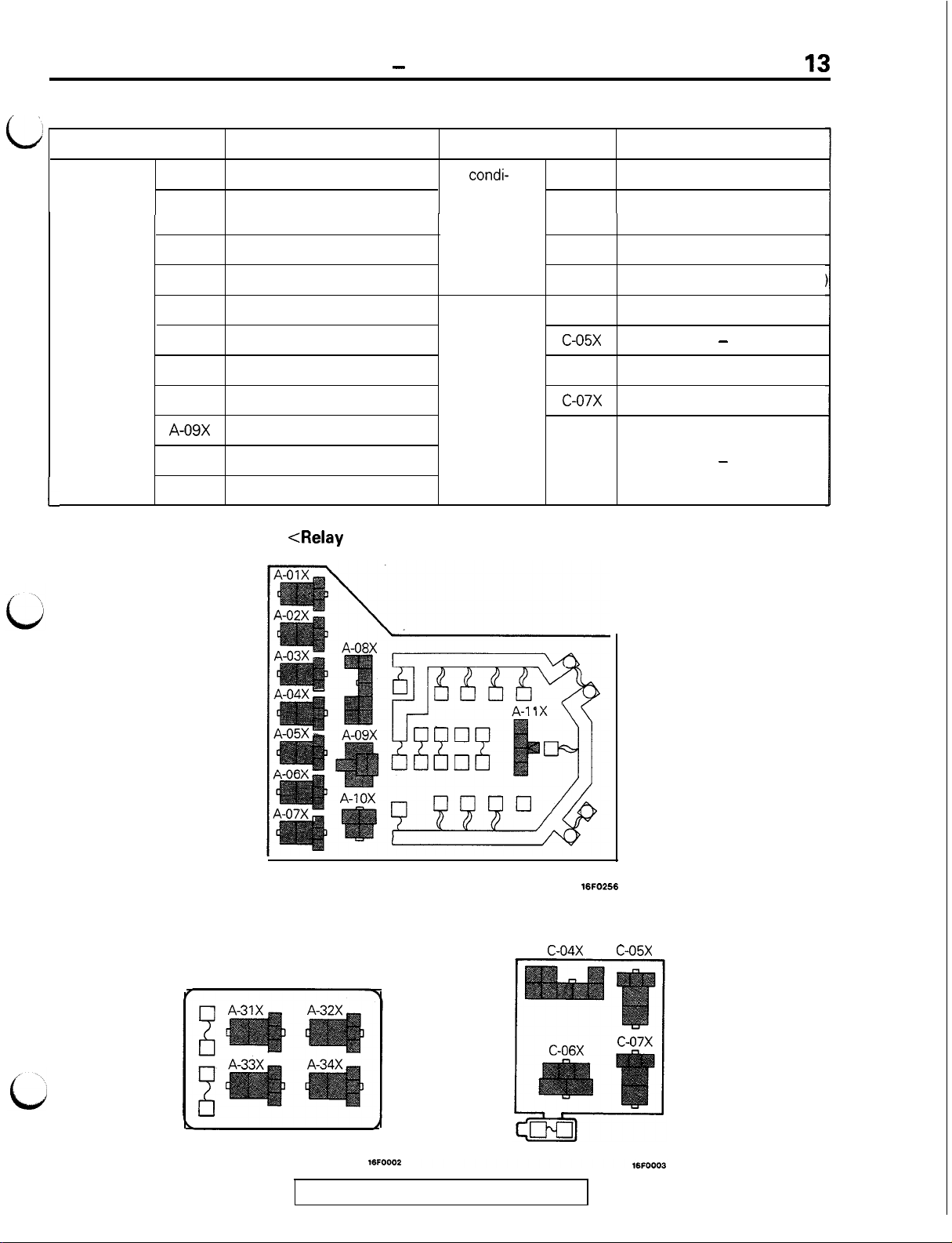
<Relay box in engine compartment>
<Air conditioner relay box
in engine compartment>
16FOOO2
TSB Revision
16FOE.6
<Interior relay box>
Page 14
12
GENERAL - Centralized Junction
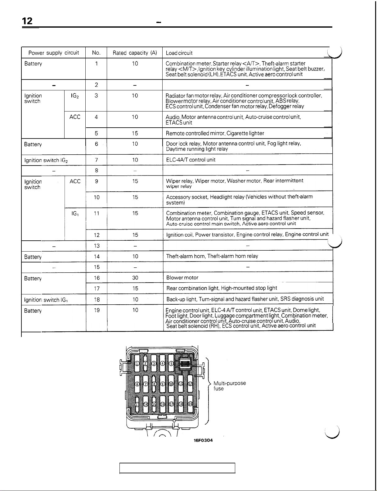
MULTI-PURPOSE FUSE (In junction block)
Power supply circuit
Battery
-
Ignition
switch
Battery
Ignition
Ignition
switch
1%
ACC
No.
1
2
3
4
5 15
Rated capacity (A)
IO
-
10
10
Load circuit
Combination meter, Starter relay <AA>. Theft-alarm starter
relay <M/T>, Ignition key cylinder illumination light, Seat belt buzzer,
Seat belt solenoid (LH), ETACS unit, Active aero control unit
-
Radiator fan motor relay, Air conditioner compressor lock controller,
Blower motor relay, Air conditioner control unit, ABS relay,
ECS control unit, Condenser fan motor relay, Defogger relay
Audio, Motor antenna control unit, Auto-cruise control unit,
ETACS unit
Remote controlled mirror, Cigarette lighter
Battery
Battery
ignition
Battery
Engine control unit, ELC-4 A/T control unit, ETACS unit. Dome light,
Foot light, Door light, Luggage compartment light, Combination meter,
Air conditioner control unit, Auto-cruise control unit, Audio,
TSB Revision
Page 15
CENTRALIZED RELAY
GENERAL
-
Centralized Junction
13
Classification Name
Relay box
in engine
compartment
L
,A-01X
A-02X
A-03X Fog light relay
A-04X
A-05X Taillight relay
A-06X Horn relay
A-07X
A-08X
A-09X
A-l OX
A-l 1 X
Headlight relay
ABS power relay
Radiator fan motor relay (LO)
Radiator fan motor relay (HI)
Pop-up motor relay
Starter relay
Alternator relay
Jumper connector
Classification
Air
condi-
tioner relay
box in engine
compartment
Interior
relay box
A-31X
A-32X
A-33X
A-34X
C-04X
c-05x
C-06X
c-07x
<Relay box in engine compartment>
Name
Condenser fan motor relay (HI)
Radiator fan motor control
relay
Magnetic clutch relay
Condenser fan motor relay (LO
Door lock relay
-
Defogger relay
Power window relay
-
<Air conditioner relay box
in engine compartment>
TSB Revision
16FO266
<Interior relay box>
c-04x c-05x
Page 16
GENERAL
- lnwection
of Harness Connector
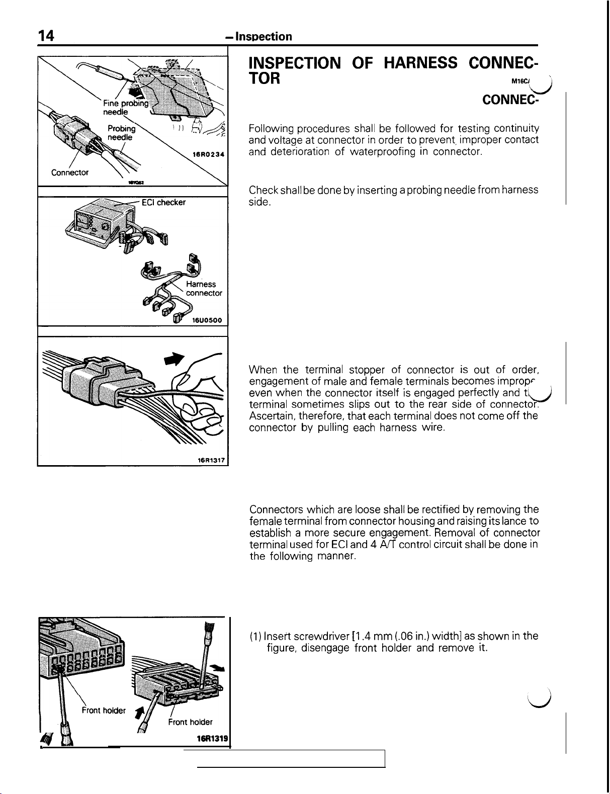
INSPECTION OF HARNESS CONNEC-
TOR
CONTINUITY AND VOLTAGE TEST FOR CONNEC-
TOR
Following procedures shall be followed
and voltage at connector in order to prevent, improper contact
and deterioration of waterproofing in connector.
CONVENTIONAL (NON-WATERPROOF) CONNECTOR
Check shall be done by inserting a probing needle from harness
side.
WATER PROOF CONNECTOR
Caution
Do not insert probing needle from harness side as it will
deteriorate waterproofing and cause rusting. To inspect
the energized circuit, use the ECI checker.
for
testing continuity
M16CI
d
’
CHECK FOR IMPROPER ENGAGEMENT OF TER-
MINAL
When the terminal stopper of connector is out of order,
engagement of male and female terminals becomes impropr
even when the connector itself is engaged perfectly and tl&
terminal sometimes slips out to the rear side of connector.
Ascertain, therefore, that each terminal does not come off the
connector by pulling each harness wire.
ENGAGING AND DISENGAGING OF CONNECTOR
TERMINAL’
Connectors which are loose shall be rectified by removing the
female terminal from connector housing and raising its lance to
establish a more secure engagement. Removal of connector
terminal used for ECI and 4 A/T control circuit shall be done in
the following manner.
COMPUTER CONNECTOR
(1) Insert screwdriver
figure, disengage front holder and remove it.
[I .4 mm
(.06 in.) width] as shown in the
14fti
19R1319
TSB
Revision
Page 17
Housing lance
GENERAL
16R1321
-
Inspection of Harness Connector
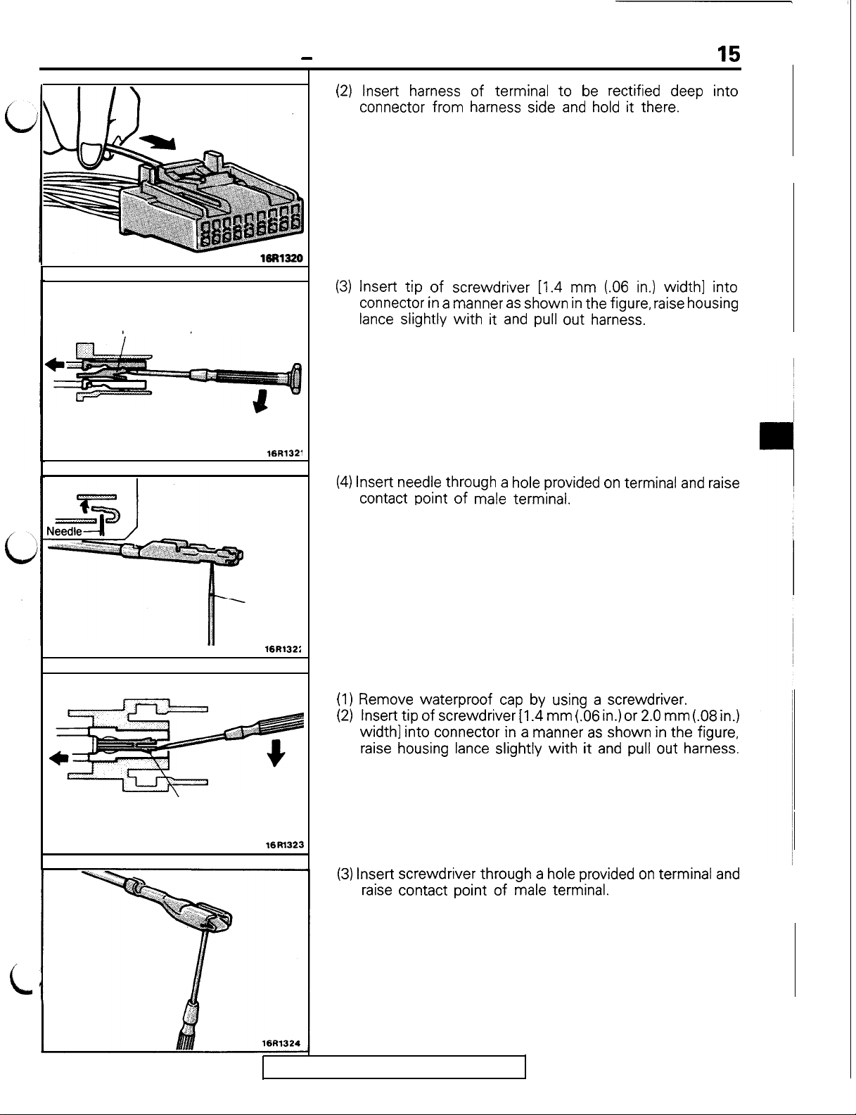
(2) Insert harness of terminal to be rectified deep into
connector from harness side and hold it there.
(3) Insert tip of screwdriver L1.4 mm (.06 in.) width] into
connector in a manner as shown in the figure, raise housing
lance slightly
Caution
Tool No. 753787-l supplied by AMP can be used instead
of screwdriver.
with it
and pull out harness.
15
Housing lance
Needle
16R132:
16Rl323
(4) Insert needle through a hole provided on terminal and raise
contact point of male terminal.
ROUND WATERPROOF CONNECTOR
(1) Remove waterproof cap by using a screwdriver.
(2)
Insert tip of screwdriver
width] into connector in a manner as shown in the figure,
raise housing lance slightly
(3) Insert screwdriver through a hole provided on terminal and
raise contact point of male terminal.
[I .4 mm
with it
(.06 in.) or 2.0 mm (.08 in.)
and pull out harness.
c
TSB
Revision
Page 18
16
GENERAL
- lnwection
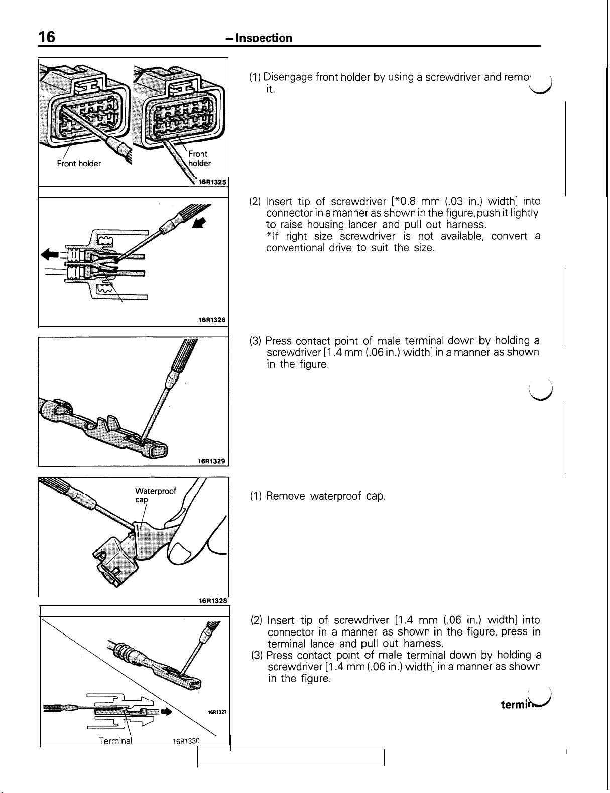
RECTANGULAR WATERPROOF CONNECTOR
1) Disengage front holder by using a screwdriver and remo’
of Harness Connector
it.
\,
LJ
I
Housing lance
yl(6R1325]
16R1326
(2) Insert tip of screwdriver [*0.8 mm (.03 in.) width] into
connector in a manner as shown in the figure, push it lightly
to raise housing lancer and pull out harness.
*If
right size screwdriver is not available, convert a
conventional drive to suit the size.
(3) Press contact point of male terminal down by holding a
screwdriver [I .4 mm (06 in.)
in the figure.
width] in a
manner as shown
INJECTOR CONNECTOR
(1) Remove waterproof cap.
I
Terminal
lance
16R1326
16R1330
\
TSB Revision
(2) Insert tip of screwdriver [1.4 mm (.06 in.)
connector in a manner as shown in the figure, press in
terminal lance and pull out harness.
(3) Press contact point of male terminal down by holding a
screwdriver [I .4 mm (.06 in.)
in the figure.
Caution
Correct lancer to be in proper condition before termi
is inserted into connector.
width] in a
width]
manner as shown
into
Page 19
GENERAL
-
How to Diaanose
17
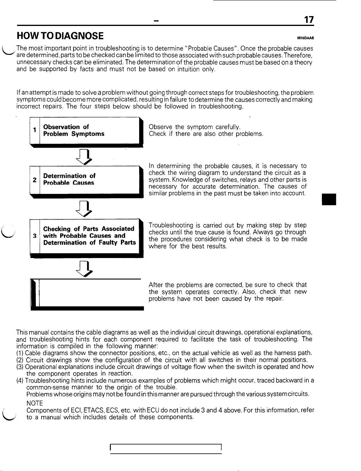
HOW TO DIAGNOSE
The most important point in troubleshooting is to determine “Probable Causes”. Once the probable causes
L
are determined, parts to be checked can be limited to those associated with such probable causes. Therefore,
unnecessary checks can be eliminated. The determination of the probable causes must be based on a theory
and be supported by facts and must not be based on intuition only.
TROUBLESHOOTING STEPS
If an attempt is made to solve a problem
symptoms could become more complicated, resulting in failure to determine the causes correctly and making
incorrect repairs. The four steps below should be followed in troubleshooting.
without
going through correct steps
Observe the symptom carefully.
Check if there are also other problems.
In determining the probable causes, it is necessary to
check the wiring diagram to understand the circuit as a
system. Knowledge of switches, relays and other parts is
necessary for accurate determination. The causes of
similar problems in the past must be taken into account.
for
troubleshooting, the problem
M16DAA6
Troubleshooting is carried out by making step by step
checks until the true cause is found. Always go through
the procedures considering what check is to be made
where for the best results.
I
After
the problems are corrected, be sure to check that
14 1
Repair and Confirmation
INFORMATION FOR DIAGNOSIS
This manual contains the cable diagrams as well as the individual circuit drawings, operational explanations,
and troubleshooting hints
information is compiled in the following manner:
(1) Cable diagrams show the connector positions, etc., on the actual vehicle as well as the harness path.
(2) Circuit drawings show the configuration of the circuit with all switches in their normal positions.
(3) Operational explanations include circuit drawings of voltage
the component operates in reaction.
(4) Troubleshooting hints include numerous examples of problems which might occur, traced backward in a
common-sense manner to the origin of the trouble.
Lj
Problems
I
NOTE
Components of ECI, ETACS, ECS, etc.
to a manual which includes details of these components.
whose
origins
for
each component required to facilitate the task of troubleshooting. The
may
not be found in this manner are pursued through
the system operates correctly. Also, check that new
problems have not been caused by the repair.
flow
when the switch is operated and how
the
various system circuits.
with
ECU do not include 3 and 4 above. For this information, refer
1
TSB Revision
Page 20
18
GENERAL
1680222
-
How to Diagnose
INSPECTION
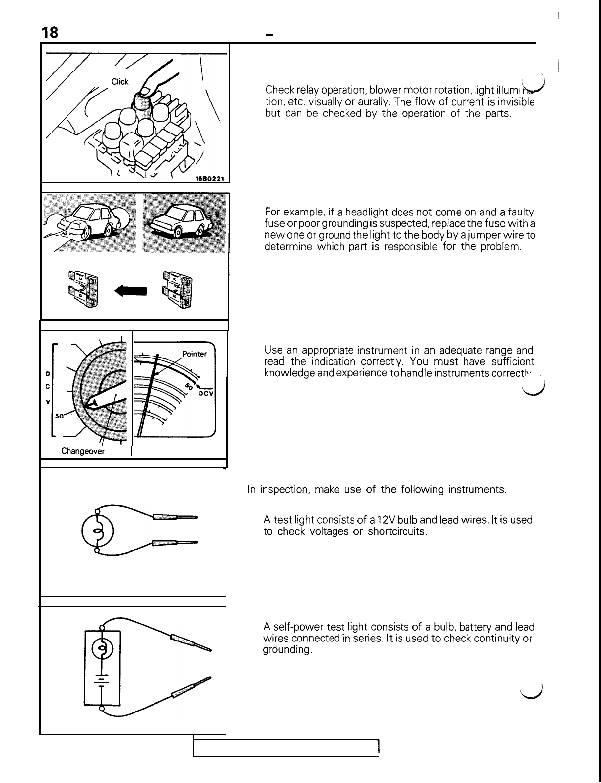
1. Visual and aural checks
Check relay operation, blower motor rotation, light illumi
tion, etc. visually or aurally. The
but can be checked by the operation of the parts.
2. Simple checks
For example, if a headlight does not come on and a faulty
fuse or poor grounding is suspected, replace the fuse
new one or ground the light to the body by a jumper wire to
determine which part is responsible for the problem.
flow of
current is invisible
ht!J
with
\
a
CIhangeovei knob
3. Checking with instruments
Use an appropriate instrument in an adequate range and
read the indication correctly. You must have sufficient
knowledge and experience to handle instruments correctI\*
\
!L)
1
1680224
INSPECTION INSTRUMENTS
In inspection, make use of the following instruments.
1. Test lights
A test light consists of a 12V bulb and lead wires. It is used
to check voltages or shortcircuits.
1660226
2. Self-power test light
A self-power test light consists of a bulb, battery and lead
wires connected in series. It is used to check continuity or
grounding.
1660226
TSB Revision
ij
Page 21
c
GENERAL
1680227
-
How to Diagnose
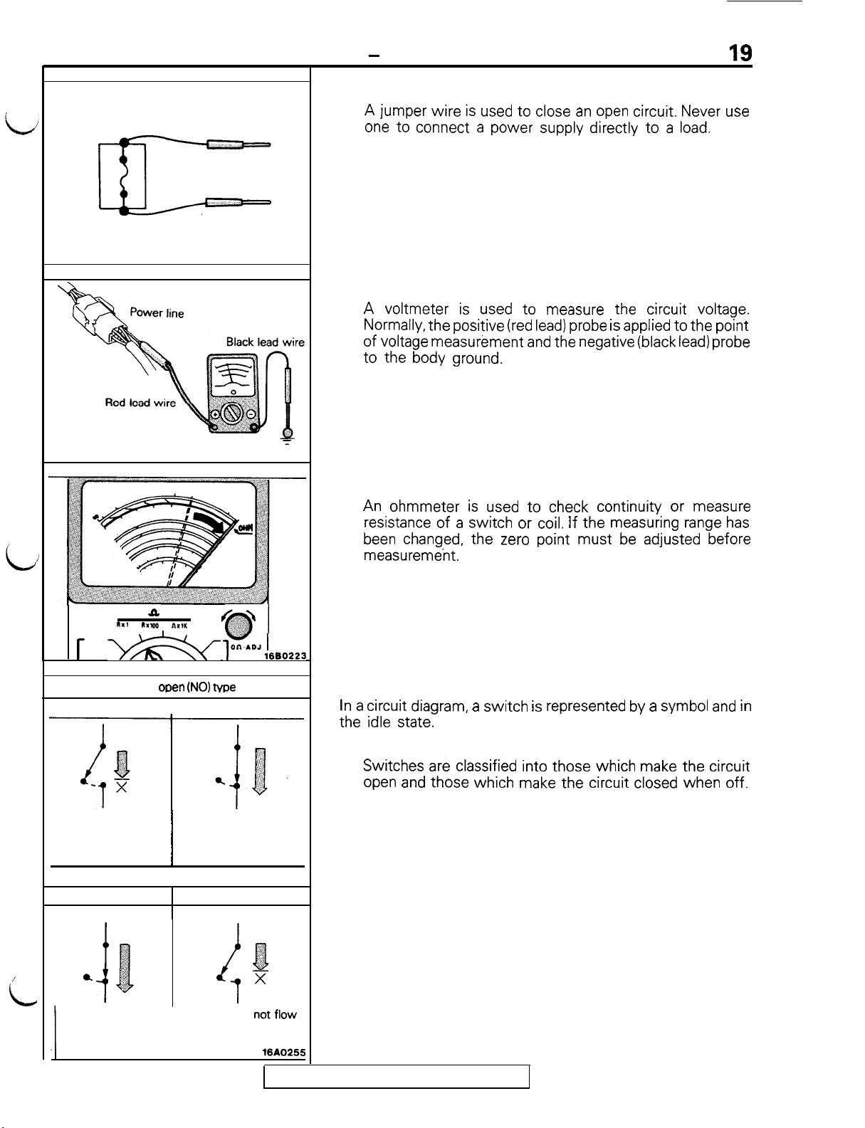
3. Jumper wire
A jumper wire is used to close an open circuit. Never use
one to connect a power supply directly to a load.
4. Voltmeter
A voltmeter is used to measure the circuit voltage.
Normally, the positive (red lead) probe is applied to the point
of voltage measurement and the negative (black lead) probe
to the body ground.
19
L
i
1x1
r b&&q
Normal open
OFF
Current flowsCurrent does not flow
a
RX100
nx,r
I
/
(NO) Me
$g
01
l”~~AoJ16B0223
ON
Ground
1680226
y
5. Ohmmeter
An ohmmeter is used to check continuity or measure
resistance of a switch or coil. If the measuring range has
been changed, the zero point must be adjusted before
measurement.
CHECKING SWITCHES
In a circuit diagram, a switch is represented by a symbol and in
the idle state.
1. Normal open or normal close switch
Switches are classified into those which make the circuit
open and those which make the circuit closed when off.
/
id
Normal close (NC) type
OFF
ON
i
0.
,,,!
-2
D
i
Current flows
1
Current does
i
1
3
‘,:
0
x
nI;I;.v,
TSB Revision
Page 22
20
r-t
GENERAL
2. SWITCH CONNECTION
-
How to Diagnose
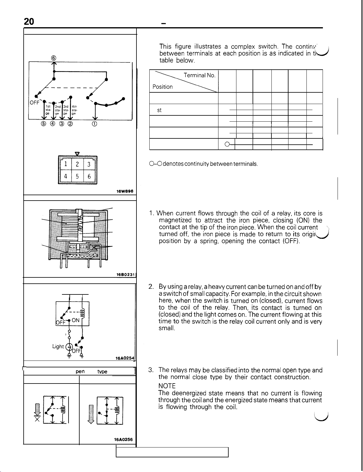
This figure illustrates a complex switch. The continu’
between terminals at each position is as indicated in t’il/l
table below.
Coil
Iron
piece
1640253
lBW898
Cover
Spring
Iron
core
Contact
1
2 3
OFF
1 st stage
2nd stage
3rd stage
4th stage
NOTE
O-O denotes continuity between terminals.
0 n 0
0
I I
I
0
j
0 1
0
1
n
I
n
4
5 6
I I
0
0
0
CHECKING RELAYS
1. When current flows through the coil of a relay, its core is
magnetized to attract the iron piece, closing (ON) the
contact at the tip of the iron piece. When the coil current
turned off, the iron piece is made to return to its origiljl/i
position by a spring, opening the contact (OFF).
4
\,
Power supply
Fuse
Light
r
Deenergized state
:.‘
-.
X
olzi
Current does not flow
,
Normal o
--
OF{
i
1 T
Relay
i
Switch
ON
n
(NO)
Energized state
Current flows
me
16A0254
16AO256
TSB Revision
2.By
3.
using a relay, a heavy current can be turned on and off by
a switch of small capacity. For example, in the circuit shown
here, when the switch is turned on (closed), current flows
to the coil of the relay. Then, its contact is turned on
(closed) and the light comes on. The current
time to the switch is the relay coil current only and is very
small.
The relays may be classified into the normal open type and
the normal cl,ose type by their contact construction.
NOTE
The deenergized state means that no current is flowing
through the coil and the energized state means that current
is
flowing
through the coil.
flowing at
this
LJ
Page 23
GENERAL - How to Diagnose
21
Deenergized state
i
Current flows
7
State of fuse blown due to overcurrent
L
Normal close (NC) type
/
Fuse
L ,
block
Energized state
Current does not flow
16A0257
16BO235
1680237
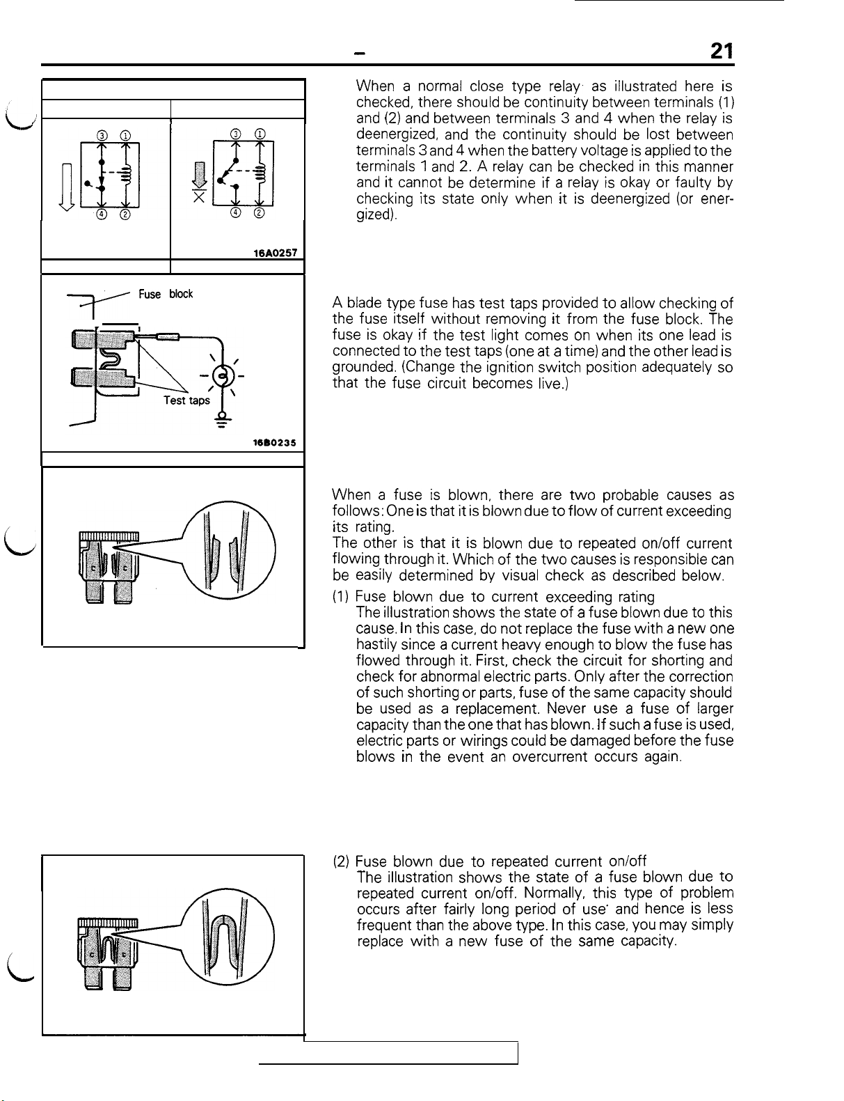
When a normal close type relay. as illustrated here is
checked, there should be continuity between terminals (1)
and (2) and between terminals 3 and 4 when the relay is
deenergized, and the continuity should be lost between
terminals 3 and 4 when the battery voltage is applied to the
terminals 1 and 2. A relay can be checked in this manner
and it cannot be determine if a relay is okay or faulty by
checking its state only when it is deenergized (or ener-
gized).
CHECKING FUSES
A blade type fuse has test taps provided to allow checking of
the fuse itself
fuse is okay if the test light comes on when its one lead is
connected to the test taps (one at a time) and the other lead is
grounded. (Change the ignition switch position adequately so
that the fuse circuit becomes live.)
CAUTIONS IN EVENT OF BLOWN FUSE
When a fuse is blown, there are
follows: One is that it is blown due to
its rating.
The other is that it is blown due to repeated on/off current
flowing through it. Which of the
be easily determined by visual check as described below.
(1) Fuse blown due to current exceeding rating
The illustration shows the state of a fuse blown due to this
cause. In this case, do not replace the fuse
J
hastily since a current heavy enough to blow the fuse has
flowed through it. First, check the circuit for shorting and
check for abnormal electric parts. Only after the correction
of such shorting or parts, fuse of the same capacity should
be used as a replacement. Never use a fuse of larger
capacity than the one that has blown. If such a fuse is used,
electric parts or wirings could be damaged before the fuse
blows in the event an overcurrent occurs again.
without
removing it from the fuse block. The
two
two
probable causes as
flow of
causes is responsible can
current exceeding
with a
new one
State of fuse blown due to thermal fatigue
1660236
TSB Revision
(2) Fuse blown due to repeated current on/off
The illustration shows the state of a fuse blown due to
repeated current on/off. Normally, this type of problem
occurs after fairly long period of use- and hence is less
frequent than the above type. In this case, you may simply
replace
with a
new fuse of the same capacity.
Page 24
GENERAL
CHECKING CABLES AND WIRES
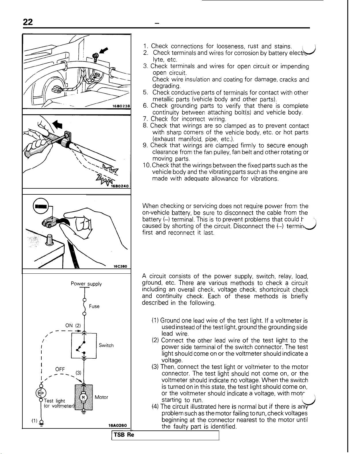
1. Check connections for looseness, rust and stains.
2.
3. Check terminals and wires for open circuit or impending
4.
5.
6. Check grounding parts to verify that there is complete
7. Check for incorrect wiring.
8. Check that wirings are so clamped as to prevent contact
9. Check that wirings are clamped
10. Check that the wirings between the fixed parts such as the
-
How to Diagnose
Check terminals and wires for corrosion by battery elect
AJ
lyte, etc.
open circuit.
Check wire insulation and coating for damage, cracks and
degrading.
Check conductive parts of terminals for contact
with
other
metallic parts (vehicle body and other parts).
continuity between attaching bolt(s) and vehicle body.
with
sharp corners of the vehicle body, etc. or hot parts
(exhaust manifold, pipe, etc.).
firmly to
secure enough
clearance from the fan pulley, fan belt and other rotating or
moving parts.
vehicle body and the vibrating parts such as the engine are
made with adequate allowance
for
vibrations.
(1) 4
HANDLING ON-VEHICLE BATTERY
When checking or servicing does not require
on-vehicle battery, be sure to disconnect the cable from the
battery (-1 terminal. This is to prevent problems that could t
caused by shorting of the circuit. Disconnect the (-)
first and reconnect it last.
power
from the
term?
d
\
TROUBLESHOOTING
A circuit consists of the power supply, switch, relay, load,
Power
supply
I
OFF
I
/---.
I/
Motor
=
16AO260
TSB
I-
ground, etc. There are various methods to check a circuit
including an overall check, voltage check, shortcircuit check
and continuity check. Each of these methods is briefly
described in the following.
1. VOLTAGE CHECK
(I)
Ground one lead wire of the
test
light. If a
voltmeter
used instead of the test light, ground the grounding side
lead wire.
(2) Connect the other lead wire of the
test
light to the
power side terminal of the switch connector. The
light should come on or the voltmeter should indicate a
voltage.
(3) Then, connect the test light or voltmeter to the motor
connector. The test light should not come on, or the
voltmeter should indicate no voltage. When the switch
is turned on in this state, the
or the voltmeter should indicate a voltage,
test
light should come on,
with motr
starting to run.
(4) The circuit illustrated here is normal but if there is an
problem such as the motor failing to run, check voltages
beginning at the connector nearest to the motor until
the faulty part is identified.
‘vision
is
test
y’
Page 25
GENERAL
-
How to Diagnose
23
Power supply
A- Short-circuit
\
,\
Switch
lllumrnation
light
7
Power supply
-T-
location
16A0502
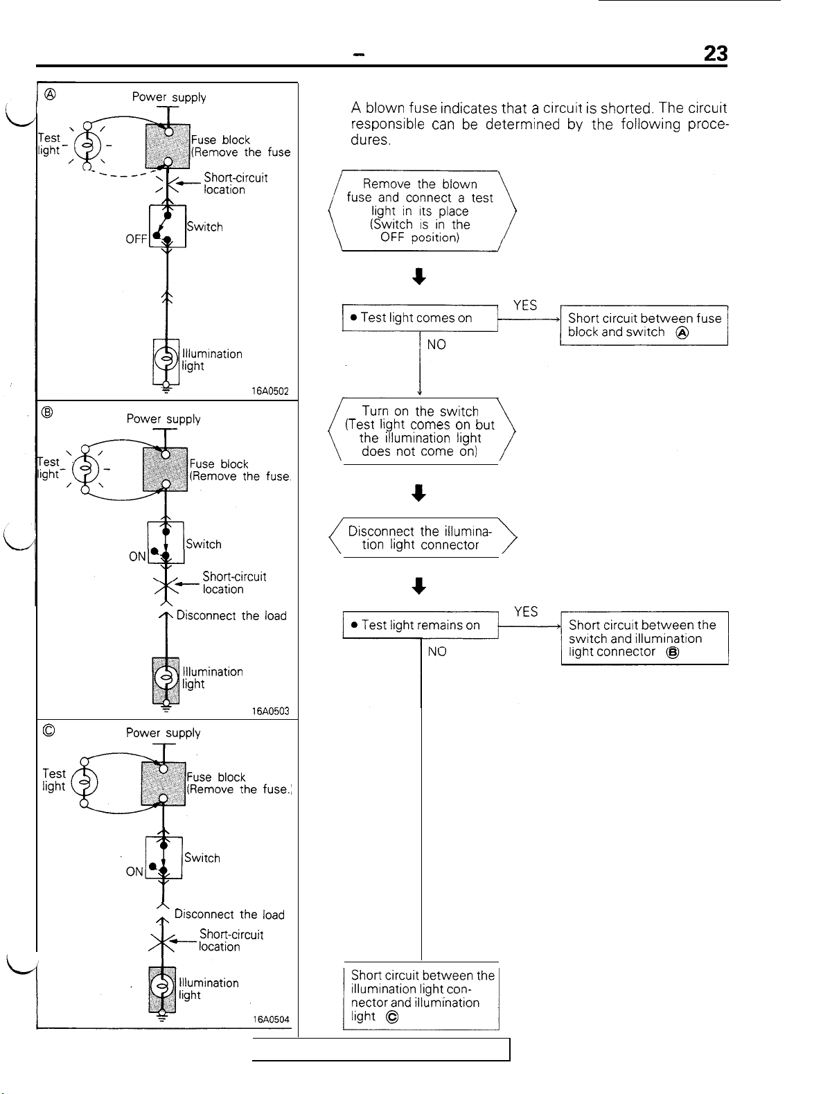
2. CHECKING SHORT CIRCUITS
A blown fuse indicates that a circuit is shorted. The circuit
responsible can be determined by the following proce-
dures.
Turn
on the
(Test light comes on but
the illumination light
does not come
switch
on)
0
Test
light
Disconnect the load
T
llluminatron
light
Power supply
-
Switch
c
Disconnect the illumina-
tion light connector
Short-circuit
16A0503
fuse.:
A
/t\ Disconnect
Short-circuit
+- location
*
the
load
TSB Revision
12s&$%z;;eI
Page 26
24
Self power
(or
ohmmeter)
c@++
1
.
_,;
test
,I
%
j :; ii,,’
‘, ‘:
light
1
+--pi
:
GENERAL
B
-0
Iii
40
P
-
How to Diaanose
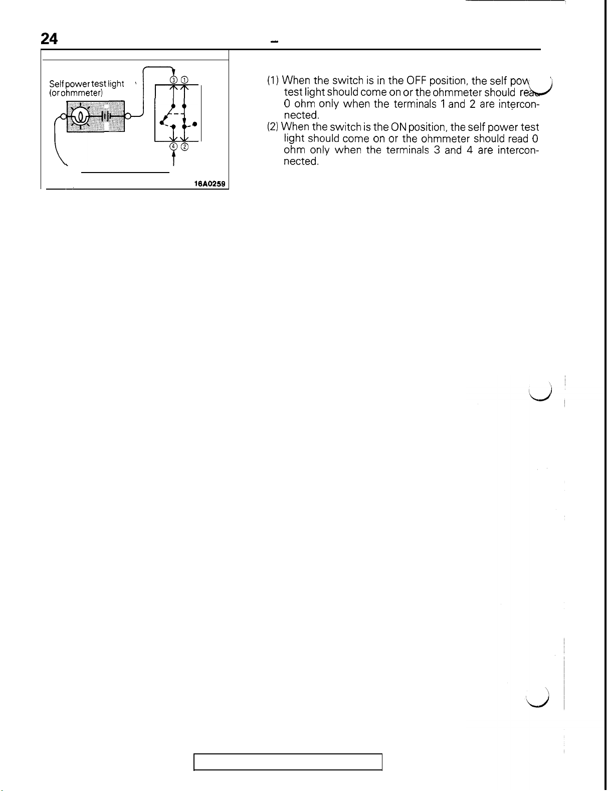
3. CHECKING CONTINUITY
(I)
When the switch is in the OFF position, the self pow
test
light should come on or the ohmmeter should
0 ohm only when the terminals 1 and 2 are intercon-
nected.
(2) When the switch is the ON position, the self power
light should come on or the ohmmeter should read 0
ohm only when the terminals 3 and 4 are interconnected.
re
&J
test
’
-.
16A0259
TSB Revision
Page 27
L
25
CONFIGURATION
DIAGRAM
Dash Panel
Engine and Transaxle
Engine and Transaxle <M/T>
Engine Compartment
How to Read Configuration Diagrams
............................................................
<A/T>
............................................
................................
............................
CONTENTS
................
34
32
30
28
27
Instrument Panel and Floor Console
Interior
Luggage Compartment
Overall Configuration Diagram
..............................................................
..................................
......................
..............
.
. . . .
. .
. . . .
M16VA- _
. .
36
.
38
. .
40
. .
26
Page 28
g
T
-a
2
s
Gj-32
--0
*-id
25,
gg
sg
nl
5.
GiO
03
2%
5.2
COO
a3
z<
55
:;
&‘a,
2%’
gg.
? 2.
a
z
3
(D
z
F
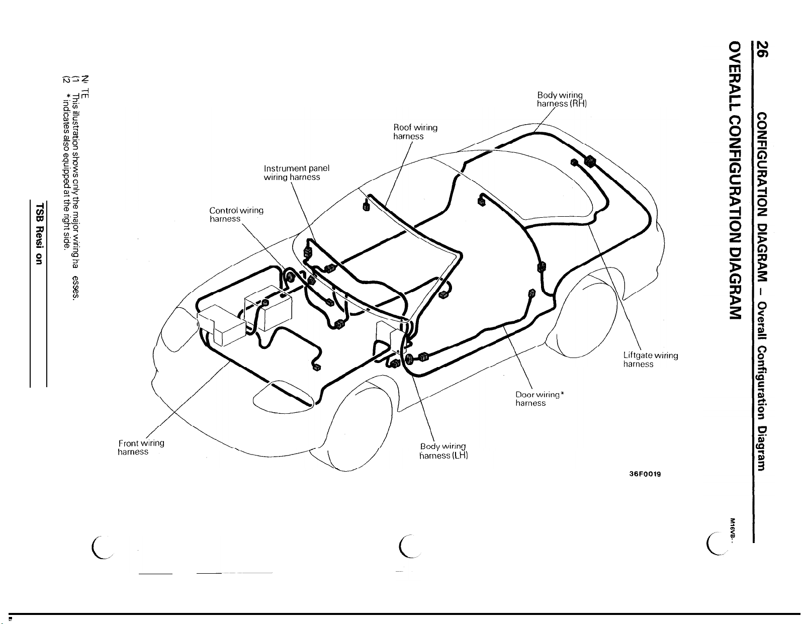
Control
Body wiring
harness (RH)
wiring
harness
harness (LH)
36FOO19
Page 29
CONFIGURATION DIAGRAM
-
How to Read Configuration Diagrams
27
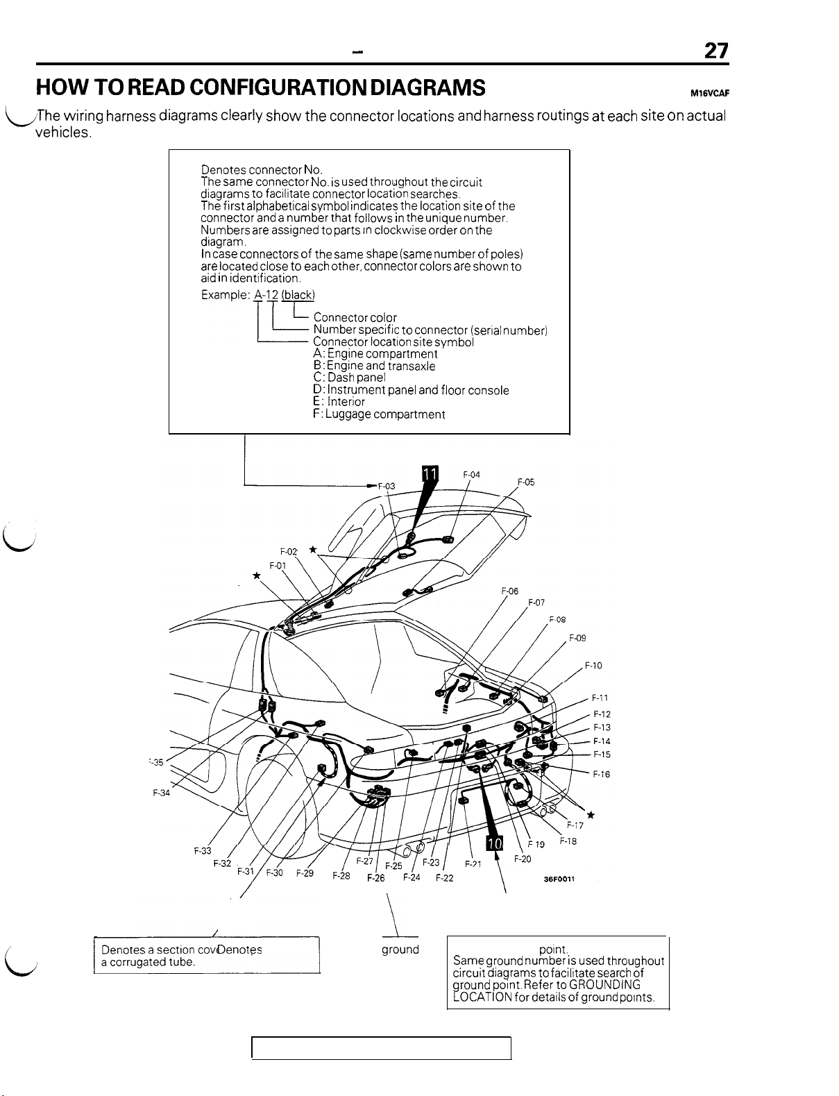
HOW TO READ CONFIGURATION DIAGRAMS
M16VCAF
LThe wiring harness diagrams clearly show the connector locations and harness routings at each site on actual
- vehicles.
Denotes connector No.
The same connector No. is used throughout the circuit
dragrams to facrlitate connector location searches.
The
first
connector and a number that
Numbers are assigned to parts rn clockwise order on the
diagram.
In case connectors of the same shape (same number of poles)
are located close to each other, connector colors are shown to
aid in identification.
alphabetical symbol indicates the location site of the
follows in
the unique number.
Connector color
Number specific to connector (serral number)
Connector location site symbol
A: Engine compartment
B: Engine and transaxle
C: Dash panel
D: Instrument panel and floor console
E: Interior
F: Luggage compartment
i
/I-
F-33 /
F-32
Denotes
77$=$5?-!3
F-28
TSB Revision
F-26
/
F-24
F-22
g!und
Same ground number is used throughout
circuit diagrams to facilitate search of
ground point. Refer to GROUNDING
LOCATION for detarls of ground pornts.
36FOOll
point.
Page 30
28
CONFIGURATION DIAGRAM
-
Engine Compartment
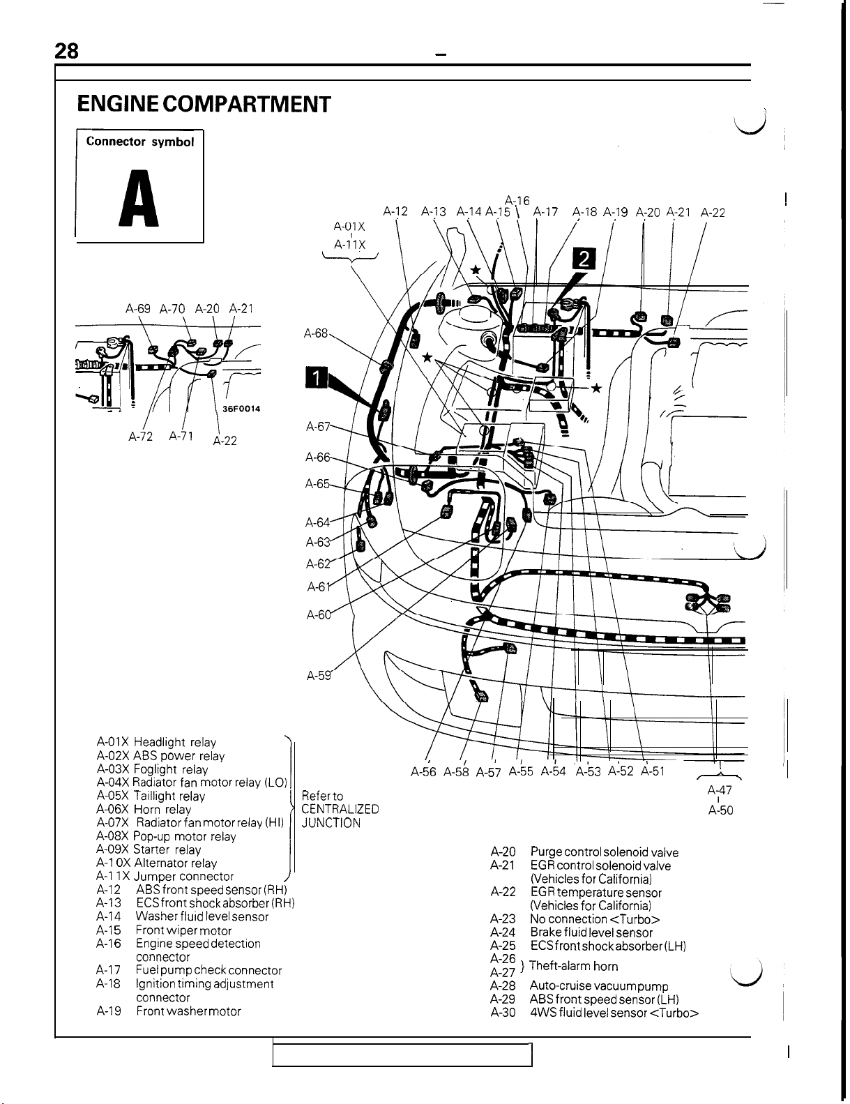
ENGINE COMPARTMENT
<Turbo>
r
ml
-
-r
A-69 A-70 A-20 A-21
A-67
A-66
A-65
A-j
\
2
A-?
A,14
3
A-,I5
A-16
\
A-l
7 A-1 8 A-,I
9
A;20
A-21
A-22
1
A-01X Headlight relay
A-02X ABS
A-03X Foglight relay
A-04X Radiator fan motor relay (LO)
A-05X Taillight relay
A-06X Horn relay
A-07X
A-08X Pop-up motor relay
A-09X Starter relay
A-l OX
A-l IX
A-l
A-13
A-14
A-l
A-l
A-17
A-l 8
A-19
power
Radiator fan motor relay (HI)
Alternator relay
Jumper connector
ABS
2
ECS
Washer fluid level sensor
Front
5
Engine speed detection
6
connector
Fuel pump check connector
Ignition trming adjustment
connector
Front
relay
front
speed sensor (RH)
front
shock absorber (RH)
wiper
motor
washer
motor
A-64
A-63
A-62
A-61
A-60
A-59
Refer to
CENTRALIZED
JUNCTION
A-56 A-58 A-57 A-55 A-64 ‘A-53 A:52 A-51
Purge control solenoid valve
A-20
EGR control solenoid valve
A-21
(Vehicles
EGR temperature sensor
A-22
(Vehicles
No connection
A-23
Brake fluid level sensor
A-24
ECS
A-25
2:;; } Theft-alarm horn
Auto-cruise vacuum pump
A-28
ABS
A-29
4WS fluid level sensor
A-30
for
California)
for
California)
front
shock
front
speed sensor (LH)
<Turbo>
absorber
<Turbo>
(LH)
/ !, ,
A;47
A-50
I
TSB Revision
I
I
Page 31

CONFIGURATION DIAGRAM - Engine Compartment
ENGINE HOOD
A-73
29
A-23 A-24 A-25
=#=k==F=r
A-46 A-45 A-44
A-31X Condenser fan motor
relay (HI)
A-32X Radiator fan motor
control relay
A-33X Magnetic clutch relay
A-34X Condenser fan motor
relay (LO)
A-35
Dual pressure
A-36
A-37)
Arr conditioner relay box
A-38
SRS front impact sensor (LH)
A-39
Front combination light (LH)
A-40
Inspection ltght switch
A-43
A-26
switch
A-27
i\
//\
\
A-42
Refer to
CENTRALIZED
JUNCTION
36FQ613
/
A-41 Headlrght (LH)
A-42
A-35
A-36
A-39
‘A-40
A-64
A-65
A-66 Hood switch
A-67
A-68 Diode (for ABS circuit)
A-69 Resistor
A-70
A-71
A-72
A-73 Inspection light
Remarks
(1)
The mark * shows the standard mounting position of
wiring harness.
(2)
For details concerning the ground point (example: 0). refer
to P.4.
Front wiring harness and headlrght
wiring harness (LH) combinatton
A-43
Fog light (LH)
A-44 Pop-up motor (LH)
A-45
) Condenser fan motor
A-46
A-47
f Horn
A-50
A-51
Fuel pump resistor
A-52 A/T fluid temperature sensor
A-53
Kickdown servo switch <AA>
A-54 Pulse generator <AT>
A-55 Radiator fan motor
A-56 Engine coolant level sensor
A-57
Active aero front venturi skirt
A-58
Fog light (RH)
A-59 Pop-up motor (RH)
A-60 Front wiring harness and headlight
wiring harness (RH) combination
A-61 Headlight (RH)
A-62
Front combination light (RH)
A-63
SRS
front impact sensor
) ABS hydraulic unit
Front wiring harness and control
wiring harness combrnation
<Turbo>
Waste gate solenoid valve
Fuel pressure solenoid valve
Control wiring harness and
solenoid valve harness combrnatron
<Turbo>
16FO174
(RH)
<Turbo>
<Turbo>
1
TSB Revision
Page 32

30
CONFIGURATION DIAGRAM
ENGINE AND TRANSAXLE <M/T>
Connector symbol
r
B
B-O8
B-06
B-O I-\
B-P7 1
-
-
Front View
j,
-
Engine and Transaxle
<M/T>
B-30
-A
B-29
B-:8
B-01
Engine coolant temperature gauge unit
B-02
Engine coolant temperature sensor
B-03
Engine coolant temperature switch
(for air conditioner circuit)
B-04
Crank angle sensor and top dead
center sensor
B-05
Throttle position sensor
B-06
Control
wiring
pressure
B-07
Control
wiring harness combination
B-08
Detonation sensor
harness and oil
wiring
wiring
harness combination
harness and injector
g$J-----8-18
*
I
B-24
B-25
<Turbo>
*
B-L5
<Non-turbo>
B-0g
B-, o)
B-l 1
B-l 2Injector No. 3
B-13 Injector No. 1
B-14 Ignition co11
B-l 5 Capacitor
B-16
B-17
B-18
B-l
9
B-20 Maonetic clutch
B-21
B-22
i-23
36FOOO7
Variable induction servo motor
(with intake control valve posrtion
sensor) <Non-Turbo>
Injector No. 5
Oxvoen sensor (LH)
‘-
) Alternator
Oxygen sensor (RH)
-
) Power transistor
<Turbo>
<Turbo>
TSB Revision
Page 33

CONFIGURATION DIAGRAM
Rear View
-
Engine and Transaxle <M/T>
31
B-31
B-32
\
B-33
I
B-23
) Starter motor
B-24
B-25
Back-up light swatch
-
B-26
-
B-27
B-28
Fuel pump relay
B-29
Air flow
sensor and
B-30
Control wiring harness and battery cable
combination
B-31
Injector No. 2
B-32
/I
B-33
Injector No. 4
Injector No. 6
<Turbo>
sensor (with intake air temperature
atmosphenc
sensor)
1
TSB Revision
1
B-34
Speed sensor
B-35
Idle speed control servo (stepper motor)
B-36
Oil pressure gauge unit
B-37
Oil pressure switch
B-38
Power steering oil pressure switch
Remarks
(I)
The mark * shows the standard mounting position of
wiring harness.
(2)
[;;d;tails concerning
(3)
“gdmeans
<Turbo>
the
ground point (example: 8). refer
that the connector
I
with
code-number is
not
Page 34

32
CONFIGURATION DIAGRAM
ENGINE AND TRANSAXLE <A/T>
-
Engine
Front View
and
Transaxle <A/T>
B-30 ‘--_
B-l 0
B-07 B-08
i
B-09 \
B-l 1
I
*B-l 5
B-17
B-l
‘B-20
8
B-01
Engine coolant temperature gauge unit
EL02
Engine coolant temperature sensor
E;-03
Engine coolant temperature switch
(for air
El-04
B-05
B-06
El-07
B-08
Es09
E;-10
conditioner circuit)
Crank angle sensor and top dead center sensor
Throttle posrtion sensor
Control winng harness and oil pressure
wiring harness combination
Control wiring harness and injector
wiring harness combinatron
Detonation sensor
Variable induction servo motor
,
I
(with intake control valve position sensor)
TSB Revision
B-l 1
Injector No.
B-l 2Injector No.
B-l 3Injector No.
B-14 Ignition coil
B-l 5Capacitor
B-16
-
B-l
7
) Alternator
B-18
B-19 B-20 Maonetic clutch
B-21
-
) Power transistor
B-22
5
3
1
36FOOO6
‘d
I
Page 35

CONFIGURATION DIAGRAM
Rear View
B-32
“-Y
\ “i
-
Enaine and Transaxle <A/T>
36FOOO4
B-23
) Starter motor
B-24
B-25
Inhibitor switch
B-26
B-27
ELC-4 A/T control solenoid valve
-
B-28
B-29
Air
flow
sensor and atmospheric sensor)
B-30
Control wiring harness and battery cable
combination
B-31
Injector No. 2
B-32
i
B-33
Injector No. 4
Injector No. 6
sensor (with intake air temperature
B-34 B-35
Idle speed control servo (stepper motor)
B-36
011 pressure gauge unit
B-37
011 pressure switch
B-38
Power steering oil pressure switch
Remarks
(1)
The mark * shows the standard mounting position of
wiring harness.
(2)
(3)
:,O;d;tails
i’ldmeans
concerning the ground point (example: a),
that the connector
with
code-number is
refer
not
TSB Revision
Page 36

34
DA.SH PANEL
Connector symbol
I
c
JUNCTION BLOCK
<Front side>
CONFIGURATION DIAGRAM
-
Dash Panel
36FOOOl
<Rear side>
;;
I
C-01
Body
wiring
C-02 and front
C-033harness combination
C-04X Door lock relay
c-05x
C--06X Defogger relay
C-07X Power
CO8
c-,o9}
Diode (for seat belt warning circuit)
EIi 7 } Column switch
c-12
Diode (for theft-alarm circuit)
c-13
Accelerator pedal switch
C-l 4
Control
panel
C-l 5
Body
panel
C-l 6
} Air conditioner control panel
C-l 7
C-l 8
Air conditioner switch
c-19
Blower
c-.20
Heater control panel illumination light
c-21
Blend
harness (LH)
wiring
window
wiring
wiring
wiring
wiring
air damper control motor
harness and instrument
harness combination
harness (LH) and instrument
harness combination
switch
C-76
36FOOO3
1
Refer to
CENTRALIZED
relay
JUNCTION
i
c-77
C-78
C-80
C-65’
/
C-64
C-22
C-23
C-24 Blower
C-25 , Air conditioner control unit
C-26 ’
C-27
C-28
C-29)
C-30 ’ wiring harness combination
C-31
C-32
c-33
c-34
c-35
C-36
c-37
C-38
c-39
c-40
c-41
C-63 &
C-62
Mode selection damper control motor
Power transistor
conditioner circuit)
resistor
<Manual
Air-inlet sensor <Full-auto air conditroner>
Air selection damper control motor
Body
Body wtring harness (LH) and front wiring
harness combination
Body
I
’ harness combination
Body
harness (RH) combination
Foot light (RH)
Body
harness combination
Auto-cruise control unrt
Blower motor
Blower motor relay (HI)
Air conditioner compressor lock controller
Air-inlet sensor
air
conditioner>
wirino
harness (LH) and control
wiring
harness (RH) and front wrring
wiring
harness (LH) and body wiring
wiring
harness (RH) and control wirrng
C-60 C-59 Ci58
(for
full-auto
<Manual
air conditioner>
air
‘d
TSB Revision
Page 37

CONFIGURATION DIAGRAM
-
Dash Panel
-31
I
\-
\
C-38
36FOO18
Foot light (LH)
C-42
Air-therm0 sensor
c-43
Engine ccolant temperature sensor
c-44
Engine control relay
c-45
Over drive switch
C-46
ELC-4 A/T control unit
c-47
C-48
c-49
Arr condrtioner control unit
c-50
<Full-auto air conditioner>
c-51
C-52
c-53
Engine control unit
c-54
Oxygen sensor <Non-Trubo>
c-55
Theft-alarm starter relay
C-56
Clock spring
c-57
Key reminder switch
C-58
Ignition switch
c-59
C-60
Steering wheel angle speed sensor
i
iA
C-61
c-62 ) Stop light switch
Clutch pedal switch (for auto-cruise control circuit)
C-63
Clutch pedal swatch (for theft-alarm circuit)
C-64
C-65
c-.66 ) ETACS unit
C-67
C-68
Front wiring harness and junction block
c-6g
combination
c-70
Adapter wiring harness and junction block
C-71
combination
C-72 Theft-alarm horn relay
Blower motor relay
C-73
Roof wiring harness and junction block combination
C-74
c-75 -
Body wiring harness (LH) and
:I$
junction block combination
c-78
Self-diagnosis check connector
C-79 c-80
Body wiring harness (LH) and
C-81
junction block combination
C-82
C-83
!
nemarks
(I)
The mark + shows the standard mounting position of
wiring
(2)
harness.
The details concerning the ground point (example:
refer to P.5.
(3)
“-)1 means that the
connectorwith
code-number is not
used.
q
),
[TSB
Revision
Page 38

CONFIGURATION DIAGRAM
-
Instrument Panel and Floor Console
INSITRUMENT PANEL AND FLOOR CONSOLE
Connector symbol
D-09
D-98 \
“T \ \
D
D-0:
D-or
D-c!6
“Y
bk4-T
D-10
\
AT----7 I
D-11 D-12
\\
I
\A--
D-40
D-01
Pop-up swatch and fog light switch
D-02
Front speaker (LH)
D-03
D-04
Combination
D-05
D-06
Defogger
D-07 Diode (for fog light circuit)
D-08 Hazard
D-09 Combination gauge
D-l 0Diode (for 4WS fluid level warning
light circuit)
D-l 1
Glove box illumination
D-l 2Photo sensor
switch
switch
meter
and ECS switch
light
TSB Revision
I
/
D-13
Front speaker (RH)
D-14
Glove box illuminatton light switch
D-l
5
Instrument panel wiring harness and control
wiring harness combinatron
D-l 6
Instrument panel
wiring harness (RH) combination
Ashtray illumination light
D-l 7
D-l 8
) Cigarette lighter
D-l
9
Cigarette lighter illuminatton light
D-20
D-21
Power seat switch
Body wirtng harness (LH) and console
D-22
wiring harness combination
wiring
I
harness and body
Page 39

D-l
D-17
CONFIGURATION DIAGRAM
3
D-l
9
D-20
-
Instrument Panel and Floor Console
D-23
D-24
SRS diagnoses unrt
D-25
1
D-26
I
D-27
ABS G sensor
D-28
Parking brake swatch
D-29
Active aero switch
D-30
D-31 ) Accessory socket
D-32 Auto-cruise main switch
D-33
Seatbelt warning buzzer
D-34
D-35 Radio
D-36
3
D-37 Rear wiper and
D-38
Active exhaust switch
D-39
Remote-control mirror switch
D-40 Rheostat
D-41
D-42
Instrument panel wiring harness and
D-43?body wiring harness (LH) combination
D-44
Instrument panel‘wiring harness and adapter
wiring harness combination
D-45
Instrument panel wiring harness and
wiring harness combination
washer switch
37
front
D-16
D-23
D-24
D\-25
Remarks
The mark * shows the standard mounting position of w&g
harness.
TSB Revision
Page 40

38
INTERIOR
CONFIGURATION DIAGRAM
-
Interior
Conlnector symbol
E-32,
E-05 E-06 E-07
E-04
E-35
E-34
1
.’
\
E-08
i
I
E-3
E-01
E-02
E-03
E-04
E-05
E-06
E-07
E-08
E-09
E-l 0
E-3;
Body wiring harness (RH) and door
wiring harness (RH) combination
Vanity mirror illumination light (LH)
Door
mirror
Door speaker (RH)
Dome light
Power window
Vanity mirror illumination light (RH)
Power window motor
Door light (RH)
Door key cylinder unlock switch (RH)
(RH)
sub
I
E-29
switch
(RH)
TSB Revision
E-28
E-l 1
E-l 2
E-l 3
E-14
E-l 5
E-16
E-l 7
E-18
E-l 9
E-20
E-21
E-27 1 E-25 /
E-26
Door lock actuator (RH)
ABS control unit
ABS resistor
Front seat belt solenoid (RH)
Door
switch
ABS rear speed sensor (RH)
No connection
Rear intermittent wiper relay
ABS rear speed sensor (LH)
Front seat belt solenoid (LH)
Door switch (LH)
E-23
E-24 E-22
<AWD>
(RH)
j E-21 1
E-20
Page 41

CONFIGURATION DIAGRAM
-
Interior
39
E-09
I I
E-10
E-l 1
I
E-l
\
E-l 8
Door lock actuator (LH)
E-22
Door key cylinder unlock switch (LH)
E-23
Front seat belt switch (RH)
E-24
Door light (LH)
E-25
Front seat belt switch (LH)
E-26
Power
E-27
E-28
E-29
E-30
E-31
E-32
seat assembly
ECS G sensor
Door
speaker
Turn signal and hazard flasher unit
Diode (for MPI circuit)
Body
wiring
wiring harness (LH) combination
harness (LH) and door
E-l 7
1
TSB Revision
36F0009
E-33
Door mirror (LH)
E-34
Power
Power
harness.
window
window
E-35
Remarks
(I)
The mark * shows the standard mounting position of
wiring
(2)
;;;d;tails concerning
main switch
motor
(LH)
the
ground point
(example:
q
l,
refer
Page 42

40
CONFIGURATION DIAGRAM
LUGGAGE COMPARTMENT
-
Luggage Compartment
nnector symbol
i
F-03
//
/F-08
F-09
/
F-IO
F-l 1
F-12
F-l 3
F-l 4
F-15
F-31 F-30
F-01
Interior temperature sensor
F-02 Defogger (+)
IF-03
Rear wiper
High-mounted stop light or
IF-04
active aero rear spoiler
IE-05 Defogger (-)
Rear
IF-06
ECS rear shock absorber (RH)
IF-07
Luggage compartment light
IF-08
ABS resistor
IF-09
Rear combination light (RH)
F-IO
I--l
1
Back-up light (RH)
ECS control unit
;I;; >
Body
f’-14
wiring
Rear
F-l 5
Fuel tank
F-1 6
License plate light (RH)
F-l 7
Body
F-18
wiring
Body wiring harness (LH) and body
F-19
F-20 1
wiring harness (RH) combination
motor
speaker
wiring
washer motor
wiring
(RH)
<FWD>
harness (RH) and fuel tank
harness combination
harness (RH) and rear bumper
harness combination
F-i9
1
TSB Revision
F-L8
F-26
F-24
F-21
License plate light (LH)
F-22
Luggage compartment light switch
F-23
Liftgate cylinder lock switch
F-24 Liftgate switch
F-25
Buck-up light (LH)
F-26
Active exhaust control unit
F-27
F-28 } Active aero control unit
F-29 Active exhaust actuator assembly
F-30
Rear combination light (LH)
F-31
Motor antenna control unit
F-32
ECS rear shock absorber (LH)
F-33 Rear
F-34
Body wiring harness (LH) and
F-35 ) wiring harness combination
Remarks
(1)
The mark * shows the standard mounting position of
wiring harness.
(2)
For details concerning the ground point (example: 0 ),
refer to P.6.
F-22
speaker
36FOOll
(LH)
liftgate
’
Page 43

i;
41
CIRCUIT
Active Aero Circuit
Active Exhaust System Circuit
Anti-lock Braking System (ABS) Circuit
Audio Circuit
Auto-cruise Control Circuit
Back-up Light Circuit
Buzzer Circuit
Central Door Locking Circuit
Charging Circuit
Cigarette Lighter Circuit
Cooling Circuit
Defogger Circuit
Dome Light, Foot Light and Ignition Key
Cylinder Illumination Light Circuit
Door Light and Luggage Compartment
Light Circuit
ELC-4
AA
Electronic Control Suspension (ECS) Circuit
Fog Light Circuit
Full Auto
Glove Box Light, Vanity Mirror
Light and Inspection Light Circuit
Headlight Circuit
............................................................................
............................................................................
Circuit
Air Conditioner
.
..............................................................
.....
................................................
....................................
........................................................
............................................................
............................................................................
....................................................
....................................................................
........................................................
............................................................................
................................................................
........................................
........................................................................
........................
....................................................................
................................................
Circuit
........................................
....................................................................
DIAGRAMS
CONTENTS
54-82
54-48
54-80
54-1
54-44
54-46
5441
54-47
54-33
142
1 19
107
125
76
81
16-3
68
I
71
115
91
Heater Circuit
Horn Circuit
How to Read Circuit Diagrams
Ignition Circuit
Indicator Circurt
MPI Circuit
Manual Air Conditioner Circuit
Meter
Power Distribution
Power Seat Circuit
Power Window Circuit
5
Rear
Remote Controlled Mirror Circuit
Starting Circuit
Stop Light Circuit
Supplemental Restraint System
Taillight, Position Light and
License Plate Light Circurt
Tension-reducer Type Seat Belt Circuit
Theft-alarm System Circuit
Turn-signal Light and Hazard Light Circuit
Warning Light Circuit
Windshield Wiper
............................................................................
............................................................................
........................................................................
....................................................................
................................................................................
and Gauges Circuit
Wiper
and
Washer
........................................................................
....................................................................
and Washer Circuit
................................................
................................................
....................................................
....................................................................
....................................................................
............................................................
................................................
Circuit
............................................
(SRS)
Circuit
........................
....................................................
................................
........................................................
........................
............................................................
....................................
M16VE.
54-76
16-25
54-19
54-l
16-l
54-52
5443
54-49
54-l
84
42
52
85
48
133
78
104
106
122
135
137
101
_
3
5
5
i
Page 44

42
CIRCUIT DIAGRAMS
-
How to Read Circuit Diagrams
HOW TO READ CIRCUIT DIAGRAMS
MlGVGAE
The circuit of each system from the fuse (or fusible link) to.ground is shown. The power supply is shown atL.,)
the top (and the ground at the bottom t’o facilitate understanding of how the current flows.
If the same connector is
shown at
tions, the connector is Indicated by fi
tor symbol shown inside.
two or
with
more loca-
connec-
An
“X” at
connector No. indicates
that the connector IS connected to a centralized
junction that is shown in
the section “Centralized
Junction”.
Indicates the operating
conditions of the engine
coolant switch, etc.
Indicates that the diagram
is continued at
next page.
the end of a
on the
v
RESISTOR
m
KXS6-AC-WM-N
L-G
4.,
1.25L-G
I
TSB Revision
indicates shield wire.
I
Page 45

CIRCUIT DIAGRAMS
) Indicates terminal No.
-
How to Read Circuit Diagrams
A broken line indicates
that these connectors
b
are the same intermediate connectors.
I
la-
\
Indicates that the terminal
iS
Indicates input/output to/from
control unit (current
tion).
Indicates harness junction where
Indicates J/B (Junction Block).
Indicates vehicle body ground
point. (Same No. as that of
ground point in GROUNDING
LOCATION)
a
flow
direc-
TSB Revision
I
Page 46

CIRCUIT DIAGRAMS - How to Read Circuit Diaarams
CONNECTOR / GROUNDING INDICATIONS
\
SWITCH(IG1)
RE;
ti
4
______--------.
TOR
7c-1B
I
Ijl
1
II_
I
J
v
$
i:
I
@
GND
I
CONTRC
Q
V
/
UNIT
-@
1
TSB Revision
I
Page 47

CIRCUIT DIAGRAMS
-
How to Read Circuit Diaarams
At the connection with a device, the
connector symbol
on the device side is
,(harness
types are indicated as illustrated.
These are indicatedasillustrated.
connection type). The two
TSB Revision
Page 48

46
SYMBOLS
Devices appearing in circuit diagrams are indicated by the
CIRCUIT DIAGRAMS - H
ow to Read Circuit Diagrams
following symbols.
Battery
11111
--I
biiiiq
Fuse
Fusible
Connector
Thyristor
;link
Female side
+
tvlale
side
Body ground
Equipment
ground
ECU interior
ground
Tl7
Motor
Piezoelectric
device
-im--
Single bulb
Dual bulb
Speaker
Horn
Thermistor
1
@
Resistor
Variable resistor
x 8
Coil
Pulse generator
@
Light emitting
diode
1
Diode
1
t
Zener diode
Transistor
J
-2
I1
Buzzer
2
0
Photo diode
Capacitor
Crossing of wires
without connection
-+
Crossing of wires
with connection
1
Chime
b
0
Photo transistor
16AO252
d
TSB Revision
Page 49

CIRCUIT DIAGRAMS’
WIRE COLOR CODES
Wire colors are identified by the following color codes.
L
Code
Wire color
-
H
ow to Read Circuit Diagrams
Code
47
Wire color
B
BR
G
GR
L
LG
0
NOTE
If a cable has two colors, the first of the two color code characters indicates the basic color (color of the cable coating)
and the second indicates the marking color.
Example: <F>
1.25G -
B
Black
Brown
Green
Gray
Blue
Light green
Orange
P
R
SB
V
W White
Y
-
Pink
Red
Sky blue
Violet
Yellow
-
1660244
Basic color
<F>: Flexible wire
CT>:
Twisted wire
TSB Revision
Page 50

48
CIRCUIT DIAGRAMS
POW:ER DISTRIBUTION
BATTERY
- -
I
q n
-
Power Distribution
ALTERNATi)R
&CATED
-
a
%
mVE
CONTROL
UNIT
r
, 30A
0 0
0
30A
MULTI-PURPOSE
FUSE
0
-iii7
‘I
KSFGER
C-06X
Egs
FUSIBLE LINK
63 @
aOA
&
-1
m
4
2 c-01
vu I\
c1:
w
t-
DEFOGGER
0
30A 40A
cc:
cu
I
0 0
-POWER
K!x~ws
.
mR
.ACTIVE
ECBEE
UNIT
8
C
c
:X35-AC-ROlOl-NY
Y::s:
mm
TSB Revision
Page 51

--
CIRCUIT DIAGRAMS - Power Distribution
i
?
FUSIBLE LINK
0
40A
I,
ALTERNATOR
R8%kiP
%
a
5
.----__
I
:
I
RADIATOR
FAN MOTOR
10 A-36
m
I
%
03
d
c
m
k3
cu
s A
I
,,l
m
I
K?
cu
,,5
\
/\
>
I
6
@
10A
CONDENSER
FAN MOTOR
AIR
CONDITIONER
* pfs t2
,
9 b;TIG;hNG
0
10A
0
COMBINATION
METER(BEAM>
I
L
"
m
65
m
d
I
Co
15A
3
4
cl
3
ti
I
0
I
15A
m
>
\c
t
m
&
I
*HORN
*HORN
RELAY
i%
N
,.
’
+
ENGINE
CONTROL
UNIT
L
xl:VEHICLES
t2:VEHICLES
1
TSB Revision
WITHOUT THEF'T-ALARM SYSTEM
WITH THEFT-ALARM SYSTEM
Page 52

50
DED
FUS:
CIRCUIT DIAGRAMS - Power Distribution
G-W
+
ES;;;
COMBINATION
J/B
dyb;F'NATION
'REAR
COMBINATION
LIGHT
.LICENSE
PLATE LIGHT
.VANITY
ILLUMINATION
LIGHT
*GLOVE
BOX
ILLUMINATION
LIGHT
$I@CTION
-RHEOSTAT
.AIR
CONDITIONER
CONTROL PANEL
*AUDIO
-
3
ti
MULTI-PURPOSE
FUSE
$h$;NATION
-STARTER
RELAY(A/T>
*THEFT-ALARM
T$l&ER
*IGNITION KEY
CYLINDER
MIRROR
LIGHT
jgkZ;EiELT
*SEAT BELT
SOLENOIDlLH)
*ETACS
'@;$$LA~~T POWER RELAY
RELAY
ILLUMINATION
UNIT
*DOOR
*MOTOR ANTENNA
CONTROL UNIT
.ggfA\IGHT
*THEFT-ALARM
HORN RELAY
ppNT-ALARM
i
LOCK
-STARTER
*ENGINE
CONTROL RELAY
-ENGINE
CONTROL UNIT
*f5!5!TDIAGNOSIS
.ENGINE
CONTROL UNIT
*ELC-4A/T
v
*REAR
COMBINATION
LIGHT
CONTROL UNIT
.ETACS
:;;;; k;;;;
*#@I Flh$ED :;;i;Ak;GHT
COiPARTMENT
LIGHT
C~~f&NATION
.AIR
CONTROL UNIT
-AUTO-CRUISE
iHF?R
CONTROL UNIT
-AUDIO
-SEAT
SOLENOID
EbiLE;EENIC
SUSPENSION
CONTROL UNIT
.ACTIVE
CONTROL UNIT
MOTOR
UNIT
CONDITIONER
BELT
(RH)
AERO
KX35-AC-ROIOYA-NY
TSB Revision
Page 53

IGNITION
SWITCH
c-59
::
7
_____--_-_-____----_--------
CIRCUIT DIAGRAMS - Power Distribution
ALTERNATOR
RELAY
m
I
ti
2
------------_
51
*IGNITION COIL
*POWER
TRANSISTOR
-ENGINE
CONTROL RELAY
*ENGINE
CONTROL UNIT
t
CgCX;ANATION
.SPEED
SENSOR
*MOTOR
ANTENNA LIGHT
CONTROL UNIT
.TURN
SIGNAL
AND HAZARD
FLASHER UNIT
.;;$yREEUISE
MAIN SWITCH
.ACTIVE
AERO
CONTROL UNIT
10A
-----
*AIR
BFl;;;R
*AIR CONDITIONEI
*BLOWER
RELAY(HI1
.A.B.
POWER RELAY
.BACK
UP
*TURN
SIGNAL
AND HAZARD
FLASHER UNIT
.&~TDIAGNOSIS
I
%iF;;;NIC
SUSPENSION
CONTROL UNIT
.CONDENSOR
f%lA!oT"R
-
10A
-_-
8
CONDITIONEI
COMPRESSOR
CONTROLLER
LCCI
MOTOR
CONTROL UNIT
MOTOR
S.
&&#fi
UNIT
--.
@
10A
t
.AUDIO
*MOTOR
ANTENNA
CONTROL
*AUTO-CRUISE
CONTROL
*ETACS
UNIT
UNIT
UNIT
*REMOTE
CONTROLLED
MIRROR
'ptf$$E
*WIPER RELAY
*WIPER
MOTOR
-WASHER
-REAR
MOTOR
INTERMITTENT
WIPER RELAY
&XS~ORY
-_
Sl
15A
--
j
TSB Revision
Page 54

52
CIRCUIT DIAGRAMS
MPI CIRCUIT
(Non-Turbo>
J/B
15A
C-83 41 7
p7liRqg
G
ml
piFiR%q]
I
I f
t-.-A---
6
A
1~
1
2> 2--
,rll
0
d
FUSIBLE LINK@
DEDICATED
FUSE
10A
8
1
c-70
rt
E
2 1
1294
Ia
-
MPI Circuit <Non-Turbo>
BA
TT
ERY
-
--
1
z
u
3
r
c
201
I
-0
1
!
c
7
0
d
::
r
STARTER
RELAY
3
----- -r-A=_6_7_
r-i;+
+-
I-
L
A/T
>
w
I
\
WITH ;!JITi;"T
AEE-
IGN
SWI'
t
R
c-31
>
E
ALARM
I
ET)
I
Jy7iiEq
5
I
I
d
>
E
.G
2
-s
M/T A/T
t
$2
cc
I
t?
CL
A
:r
Iv
\r:
!OR
7
5
I
m
d:
-
A/T
%
m
6
25
-18
I
--------
&I ho8
M/T1 A/T
3
I
ENGINE
CONTROI
RELAY
c-44
;2
-
KX35-AC-R01502-NY
I-
-5
ta
TSB Revision
cl
-52
I
I
I
Page 55

L
i
D-04
r
D-03
IN
ITIt
(IGl)
TCH
3
I
??A
7
1r
--SL
\I
7:"
z
d
6
\'I
7
Liz
6
0
7
I
m
.5
77
I
CIRCUIT DIAGRAMS
C-82
J/B
D-44
p7!xsEq
COMBINATION
METER
-
MPI Circuit <Non-Turbo>
r---
53
SPEED SE
(REED SW
I
r-
j
F-14
TSB Revision
Page 56

54
CIRCUIT DIAGRAMS
AIR
FLOW
SENSOR
B-29
i-
4E
SENBOR
I \,
"7 "5
NTAKE AI
MFJERATURE
\/
"6
- MPI
-8
ATMOGPHERIC
)mISOR
Circuit <Non-Turbo>
B
\I \I \I \,
"1 "2 "4
AIR
FLOW
SENSOR
"
CRANK ANGLE
AND TOP DEAD
CENTER SENSOR
km[
B-04 d
ez
$j
3
/\
ENGINE
CONTROL
RELAY
C
m
Y
3
3
nl
d: c
I
c
.----J19
r
I
I
1
I
I
I
I
I
I
I
I
I
I
I
I
I
‘yE
I _
%
cu
s
“F
I2
cu
c
B
2
CL
m&2-
f-r
G
31 ’
1
I
5V
b
1
I
1 ’
; f
I !
; I
’ L--..
I
!
>
CL
0
- ----.-
I
I
I
I
I
3
1
6 >
E h
65
--__-__
1
V
&
5V
I f h
z- 9c:
J g
m
70
--------------------MEL&
\/
"4 "1
ix
Ll
v
- - -~~~I-~E-
\/
"2
3
.ll
V
_
_
CONTROL
UNIT
_
_
_
-
K3l
h/
KX35-AC-RO5Q2A-NY
%
m m
n
AA
= SENSOR
--
d
OXYGEN
c-55
TSB Revision
I
I
I
I
I
I
I
3,
!
J
7
it
1234
!A
I
y
7
Ei
w
7
ON
-
THROTTLE B-05
g~f&goN
~~~
m
ENGINE
COOLANT
~~~~~~ATURE
B-02
@J
d
Page 57

ENGINE
CONTROL
nl7, ,I\>
CIRCUIT DIAGRAMS
-
MPI Circuit <Non-Turbo>
55
jR
YW
I
1
1
6#
,12
1.25R
I
-q&J&g
B-11
I
:,1.252
\
I
SW
I
1
B-33
I
s b-32
I
i
-I
I I I
E2 Ic4_--~~~-~~_-~~~-------~~---
4ikbd
4 -
_.
1
a
INJECTOR
2
-----------------
58
rl
I I
I I
I I
t I
I I
TSB Revision
Page 58

56
--
CIRCUIT DIAGRAMS
J/B
(h!;!$&;RPOSE)
-
MPI Circuit <Non-Turbo>
;f;T,IL$GHT
Iu2ldI-l
I
DEFOG
ncr n\.
mxn i
;GER
f;d;;T
I C
CLUTCH
WITH
#;FiXfJISE d MJ;4XE;UiSE
I
2
,UN&-“l-Y
C-61
%
03
WITHOUT
*
STOP
C-52
.
;E;iCATED
i
11
[r:
h
9;
m
I
0
DIODE
E-31
:8
6 A-67
2?.-.------
d
47
A-36
(Lb
-r
4
-----__--~~~___---~_---
101 c-54
f
----------_
115
T
KX35-AC-I0502B-NY
--
AIR
E;/yRzlONER
UNIT
TSB Revision
POWER
3
f
J
TRANSISTOR
!z
.L
7
ENG I NE
COOLANT
#;EBATURE
(FOR AIR
CONDITIONER)
\
tLJ
--
~
Page 59

CIRCUIT DIAGRAMS
ENGINE
CONTROL
RELAY
-
MPI Circuit <Non-Turbo>
-4A/T (
NTROL
IT
I
-
57
------------------
/@
107
B-06
2
3
I
--------
? ----
I
--------------
5v
A
Q
5v
i
E
59
i
1E-----
ENGINE
CONTROL
UNIT
B-38
r
1
TSB Revision
Page 60

58.
---.
MPI CIRCUIT
(TU~ILIO)
CIRCUIT DIAGRAMS
FUSIBLE LINK@
-
MPI Circuit <Turbo>
BATTERY
I
zl
E
J/.8
m
d?
TED
0
r
4-l
3 A-67
3
::
I
:
<
4
\$
:
D-15
/2l%@lq
--
m
-
f
I
a
X35-AC-RO503-NY
i?
0
r
I
71
9
,
;
c
)
77
1
1
ENGINE
CONTROI
RELAY
c-44
OFF--ON
\/ \,
cr"4
"5
5c 12
---
1?
I
$
.G
II:
1
E
%
cu
c,
B
&l
m
&
:
5
5
c
h
z
:
Y
"8
7
Ll
208
m
\/
"E
C
\I \I
,
“7
ON*-OFF
\I
-?2
‘L
0
-5
-5
c3
El
-52
TSB Revision
Page 61

CIRCUIT DIAGRAMS
-
MPI Circuit <Turbo>
59
i
L
i
@
IGNITION
SWITCH(IG1)
5
I
E
7
C-82
J/B
of;
I
-----+d-71
P-44
3
I
t;
!
J
IT
d:
,
‘
E;uEkNATION
D-09
[ml
AL
\/
r
7
1
*9
I
SPI
SEE
-
ID
10R
-
I
ENGINE
CONTROL
RELAY
fj;%k -
RELAY
B-28
7
5
cl
!
E
@
v-
%kPUMP
CONNECTOR h
. FUEL
: RESISTOR
I
9 c-34
J
pTim$q
cu
c ,6
[--+
/ Y
; L%
I
c-d
I
-
I
1
FUEL
PUMP
I
I
f2
I cu
I .
I
’ c,,5
L--
El?
CL.
v-
,\
(I
F-14
PUMP
A-51
06
---------__--
1
______
.
.ll
..-
#
2
TSB Revision
i524
56
-a
!l
7
ENGINE
CONTROL 1
UNIT
4
-Q
q
Page 62

60
CIRCUIT DIAGRAMS
E
AIR
FLOW
SENSOR
B-29
-
MPI Circuit <Turbo>
B
AIR
FLOW
SENSOR
CRANK ANGLE
AND TOP DEAD
CENTER SENSOR m
4-1 B-04 '
3
$
I\
L
L
ENGINE
CONTROL RELAY
\I ,,
"7 "5
7:
Qi
s
\/ \/ ,L
"6 “1
;I
h.
I
B
’ L--
I
I
I
>
&
0
I
I
f
"
2 4 3
is
m
I
6 >;
.-.I
E
:I”
I
p'
---
34
72
ii? OL
cu
- L
c
---
.-----------
67 63
a
”
7
>
i
I
----------------
v
ENGINE
tETRoL
B
----_--
------
@
Xx35-AC-R0503A-NY
TSB Revision
1 1.
m
vz
&
l
CIJ
m A
,ENGINE
,
Ld
COOLANT
FE/M&ATURE
B-02
m
Page 63

0.85R
0.85R
ENGINE
CONTROL
RELAY
B
1.25R
CIRCUIT DIAGRAMS -
&
&
.MPI
Circuit <Turbo>
INJECTOR ;
I
..
&
61
RESISTOR
;
55
-------------------------
sj
i--,
.---
l&,7 -JO
-- ---
.---
1 iI
6
I
----,
Sk1
4
’
I
G3
21
OXYGEN
SE%lR(RH,
ml
I
1
I
A
I
I
8
/
592
2 2
w
I
7
m
.
>
2
m m
d d
II
.lI
-I
m
I
m
z
&I
!
2
m
1
Ez
Q
1
------_-_____________
5R
r'l
1 I
31
I
I I
I I
t I
I I
I I
I I
t I
I I
I I
,,I
I I
I I
I I
I I
i I
I I
7 II
I I
m j
i
2 1
I I
k
B-08
ii$@
J
1
-I
EGR
$~~W~~ATURE
53
1
?
s
m
m &
J
I
V2
Vl
s
_o
A-22
m
B-37
~
TSB Revision
Page 64

62
CIRCUIT DIAGRAMS
-
MPI Circuit <Turbo>
J/B
MULTI-PURPOSE
(
FUSEQ
STOP
LIGHT
SWITCH
C-61
I
2
34
a3
ON
4
I
I
I
I
-__-_---------_----_-~--~~---
I-
I
I
I
I
I
I
I
I
I
I
1
I
OF
-*LlFF -
v
m
k5
m
d
ON
L?
m
d
A
2
3
>
-------
22
$ff&LIGHT
$4
:----.
10
.L
Ic
iTti
--
:----.
23
&j
i
DEFOGGER
RELAY
li:g
i
,-------~------_
101
-----------__
116
#B&
CONTR;
t----------
I
I
~
c-29
.
1
UNIT
3
I;:
12
3
102
--------___
103
6-541
I
\
d,
I
KX35-AC-R01503B-NY
AIR
E;/Z;;;ONEh
UNIT
#-YEB
RELAY
6
-------.
I
8
-----
-11
!A
A-Xi
POWER TRANSISTOR
IC
TSB Revision
J
II:
Q
J
A-67
8 C-14
f!FRgMq
--
--_.
-----
3
&
Dz
I
Es
-----_-----____
3
I
--
t
f&ROL
ACTIVE
E
ix%%*
Page 65

CIRCUIT DIAGRAMS
-
MPI Circuit <Turbo>
63
/
L
ENGINE
CONTROL
RELAY
%2
r----
I
I
I
I
I
I
I
I
1
I
2,(
I
1 X&
I
I
I
I
I
I
I
I
I
I
I
L----
@L
md7
II
2
A
FUEL
PRESSURE
SOLENOID
VALVE
/
___---___--__-
L
4
-_---__--__--_-
B
a:
i
A-70
A-72
._-----__-----
i
E
4
---__--
13
s
-em------:
112
.--_I
04
pEzimmqa
C-B
4
------
2 B-06
‘Y-
J
:
3
1
lal
.
ON
~
POWER STEERING
OIL PRESSURE
i
SWITCH
;jF&DIAGNOSIS +F;i;;ON
CONNECTOR
6W
~~
zrlb~
rmwqr
10
--
-1
\y
3
A
1
! A-18
r
ADJUSTMENT
CONNECTOR
a
TSB Revision
1
Page 66

64
CIRCUIT DIAGRAMS
COMPONENTS LOCATION
-
MPI Circuit
Detonation sensor
EGR control solenord valve
<Calrfornra - Non Turbo, Turbo>
Fuel pressure control valve
lgnrtron tirnrng adjusting terminal
NOTE
The
“Name”
column IS In alphabetical order.
<Turbo>
I
Symbol
A
0
G
N
T
Z
Y
S
B
P
V
M
Q
Name
InhIbItor switch
Injector
ISC servo (stepper motor)
Oxygen sensor
Power steerrng 011 pressure switch
Purge control solenord valve
Resrstor
Self-dragnosrs output termrnal and self-dIagnosIsI
data transmtssron selector terminal
TDC sensor and crank angle sensor
Throttle position sensor (with built-in idle swatch)
Variable induction control servo (DC motor)
(with built-in induction control
sensor) <Non Turbo>
Vehrcle speed sensor (reed switch)
Waste gate solenoid valve
<A!T>
<Turbo>
valve
<Turbo>
position
I
K
L
E
H
X
/
I
W
R
D
C
J
F
U
TSB Revision
I
Page 67

CIRCUIT DIAGRAMS
-
MPI Circuit
65
<Non Turbo>
air temperature
sensor
RR
\
-_ b
\ Oxygen sensor,
ii
Rm-llP
““J’- --“--
s.e”snr
\\
Vehicle speed sensor
(reed switch)
I
7FU100~
TSB Revision
Page 68

<Non Turbo>
CIRCUIT DIAGRAMS - MPI Circuit
P
I A /I
II
*
CL% LJ/
-
II
AA
--rT
otor) (with built-in induction
control valve position sensor)
I
\
7FUO802
,
7FUO647
7FUO927
,I ,
Injector
\
\
I
\
j
I-,
( ~~Z%S&istor)
u
7FUO803
7FUO646
.
lta
1 Engine warning
I
k Self-diagnosis output terminal
and self-diagnosis/ data
transmission selector
I
68FOOll 1
7FUO999
TSB Revision
Engine control
unit
16FO292
Page 69

CIRCUIT DIAGRAMS
-
MPI Circuit
67
<Caliiornia - N&Turbo,
EGR control solenoid valve
4) / / / 7FUlOll
Turbo>
[TSB Revision
L”
Page 70

CIRCUIT DIAGRAMS - Cooling Circuit
COOLING CIRCU1.T
RAD
FAN
RAD
FAN
i
FUSIBLE LINK@
m
A-04X
/\
OFF-$3N
'/4
5
-------
7
1
-RADIATOR
"
ZfA!OTOR
\/ _ (LO) (HI) OFF-,%
'3
,5
"
-
-------
IGNITION
SWITCH(IG2)
m
&
2 C-62
J/B
0
10A
2
t
'4
C-69
1
:.A-07X
g3
3
123
4
5
2L-R
@
LX35-AC-B080Y
-NY
6
EslsToRl--$
y !i!!Jt:;;
RADIATOR FAN
1
TSB Revision
ASSEMBL'J
!!!!E;@
I-& ml
I
I
Page 71

CIRCUIT DIAGRAMS
-
Cooling Circuit
69
1
cd
2L-R
@
r--’
FUSIBLE
LINKQ
m
I
%
,_-___,,2_0--_-------___,
>
I
d
@I
20AC
G
EBCATED
7
0
7
2
5
i%BPE!
CONTROL
I
1
/
I
I
i---------
,,5
ITIONER
OR LOCK
ER
0
CL
I
-------------------
?
w
0
CL
RADIATOR
Efi/Ti;zOR
RELAY
J
A-32X
r
L:
'
RF
RELt
I'OR
ITOR
,(LO)
)
:----
m
G-B
@
A-45:
A-36
m
@$a[
i
El
TSB Revision
Page 72

70
CIRCUIT DIAGRAMS
COMPONENTS LOCATION
-
Cooling Circuit
Name
fan motor relay (HI)
fan motor relay (LO)
Radiator fan motor relay (HI)
Symbol
B
B
A
Name
Radiator fan motor relay (LO)
Radiator fan motor control relay
Therm0
I
sensor
1 +--!-d
\\
16FO264
Symbol
A
B
C
L
Thermosensor -
16FOO54
TSB Revision
1
Page 73

CIRCUIT DIAGRAMS
-
ELC-4 A/T Circuit
71
i
c
ELC
i
I
4-SPEED AUTOMATbgTILRANE
WITCH(ST)
@LE CIRCUIT
WE
A!
f
T
WITHOUT
pi- '; pm&
2
INHIBITOR
SWITCH
WITH'
%
:t8
-___-_-----__ --_-________
t
STARTER
i-
J/B
04
L
314
q
’ \
2‘4D---k R
\I ,, \, \I \, \8
5 1 6 2 7'3
:m
ma>
IPI
I I
‘>
six00
P Lq,
/
IGNITION
SWITCH
-3----
2'
(IGl)
5410
+g
T'
11
%
03
d
EEbTUP
I
L-R
B-Y
R-L
W-B
Y
Y-B
V-R ”
o
o
o
o
g
COMBINATION
METER
D-03
gtilig
X35-AC-R0701-NY
1
B-Y
RHEOSTAT
8PF
PWR
B-.Y
I
1
TSB Revision
J,3
1'
I,4
1'
(R-G)
G.-Y ,[
-
,,
3
,,
I
4
-c-14
(R-G)
G-Y
B-Y
,ll
B-Y
nc-15
(R-G)
B
G-Y
9
(B-Y)
@
Page 74

72
CIRCUIT DIAGRAMS
-
ELC-4 A/T Circuit
123 c-30-
456
Ii3
L-R
@
IGNI:
SWIT(
3
:
I
\,
I
XI<
R
I
I
‘i
E
,
IN
m
WR
)
OF
,6
C-69
TAIL LIGHT RELAY
o
B-Y
o
R-L
W-B
'@
Y
,g
Y-B
0
Y-R
87
B CR-G)
8
G-Y
r
11
I
EH
15 12
--
J
Is
s
& &
li
AUTO-
CRUISE
#$~ROL
-------------.-
.&
G-R
R-Y
'5yj
64;1
G-L
C-4iS4(W
j-
--
TSB Revision
Page 75

CIRCUIT DIAGRAMS
-
ELC-4 A/T Circuit
ERIIiBs E
b
C-68 $ 1
-r-ii
10A
fl
.J
(COOL)
AIR CONDITIONER
COMPRESSOR LOCK
CONTROLLER
oi
&
I
A/T FLUID
@dgd[ATURE
(HOT)
Lrf
.------
:
3
&I
3
d
17
------_
I
12
3
I
E9
A-52'
I
5
: iszza 106
.---_-_-_-
63
m
Ea
ENGINE CONTROL UNIT
rckfQi4
&gj7
&6@J5g
I
I
1
7------ 9---j-
L
/
Ii
Ii
L
,’
AUTO-CRUISE
CONTROL UNIT
:
La
9
.
-------
j
G
a
>
L-----
h
5
5YL~~DIAGNOSIS
CONNECTOR C-79
10
SPEED
SENSOR
(!#'CH)
3
l&$l
POWER POWER
TRANSISTOR TRANSISTOR
m%OWN
SWITCH
A-53
d
(DOHC-Non-Turbo>
5
63 ml
I
DOHC SOHC
3
’ I
3; I
‘I
!
1
KX35-AC-R070¶A-NY
TSB Revision
Page 76

74
CIRCUIT DIAGRAMS
-
ELC-4 A/T Circuit
ENGINE CONTROL UNIT
5V
‘la
I-
4
I
P
E
___~~--__--~_---~~---~~~~-~~---
5v
fl
q16 ql2 m
----
kki
I
-I
i7
ml
PULSE
GENERATOR B
if
i ’
I
L
I
w
---
8
-A
&Igi?ATOR
/
--
m
-
--.
$
59
2
--.
I
z
d
-
--
1
--_
3
--
%I
_
-
a
E
J
!zL7
,
A
A-54
f ELC-4A/T
1
CONTROL
! UNIT
B-27
GND GND GND
m
c
n
GND
!j
L-
mm
1
1
TSB Revision
Page 77

CIRCUIT DIAGRAMS
COMPONENTS LOCATION
-
ELCQ A/T Circuit
75
L
PJT
fluid temperature sensor
ELC4
A/T
control unit
Engine control unit
Name
Symbol
A
C
C
Name
Kickdown
Pulse generator
Throttle position sensor
servo switch
Symbol
A
A
B
19FO134
A
L;
Pu
ge
P
I
/
16FO29i
1
TSB Revision
Page 78

76
BUZZER CIRCUIT
[YS&B
E
b
T
@
10A
%
/\
/\
7
C-68
B
CIRCUIT DIAGRAMS
-
Buzzer Circuit
IGNI-J
SWIT(
?
E
0
35A
3N
(IGl)
d
C-80 4
/~I
cp
lx
I
WHEN
KEY,
IS REMOVED "
DIODE/ + *
BUZZER
1
flzmq
2
r-----
L
m-q---;
DIODE1 !
C-OS L
3
C-80
piFi=mq
3
&
D-43
9
?
0s
101
zt;
)
(
iii:
I
I
102
Y
>
3
g:
$
1
d
K35-AC-RCQOQ-NY
>
t
DOOR
SW!TCH(LH)
TSB Revision
?I
~EL~~DIAGNOSIS
CONNECTOR
#ET
pgggq
Rx
fg@q
c-79
y-------y----
'54
m 57'1
V
I
;
I
ETACS UNIT
J
59=
I
H
tl:VEHICLES WITHOUT
THEFT-ALARM SYSTEM
z2:VEHICLES
THEFT-ALARM SYSTEM
WITH
\
,i
Page 79

CIRCUIT DIAGRAMS
-
Buzzer Circuit
77
COMPONENTS LOCATION
I
L
19FO134
ETACS unit
/;/
Name
unit
Symbol
A
16f0354
1
TSB Revision
Page 80

78
CIRCUIT DIAGRAMS
-
Power Window Circuit
POWER
r-----------
ONE-TOUCH DOWN CIRCUIT
WINDOW
CIRCUIT
POWER
WINDOWS
RELAY
FUSIBLE
LINK@
m
I
%
,,5
/\
-___-___-----_
c-07x
128
4
5
ETI
m
‘4
I
ti
-____-__---__---__-_-----------------E-34
POWER WINDOW
MAIN SWITCH
1 (LHI 1
AtL
,
~__-_------_------_-_
m
d9
/I
J
LOCK
SWITCH
*OFF
+-A----
ON
8
up l’m’l
l--f
\
: \
R-B
:
,,l
/\
\I
3
iI
A
X35-AC-RIYOI-NY
a
0
TSB Revision
(LH)
ar5m3
I
t
R
%
1
I
it
7.
c?I-u
POWER WINDOW MOTOR
E-01
POWER WINDOW
SUB SWITCH
E-06
Page 81

CIRCUIT DIAGRAMS
-
Power Window Circuit
IGNI'
EKiBsE
6
SWITl
ION
H (IGl)
79
POWER
WINDOWS
RELAY
>
I
r
I
I
I
I
I
I
I
I
I
I
I
I
I
L
.---------
---~~--_--~__---_
16"
-------_
Xl
4
J/B
n
Ii.
10"
--I--
*O*b
JUMPER
CONNECTOR
14
7 c-a2
10A
-
7
3
c-80 f7mZgq
5%--,
I
-----
T7*1
E
igr2
E
1234
m
56
78
/ ;gFS
1
7
3
>’
w
&
1
3 c-79
1
SELF-DIAGNOSIS
E-15 1 2
E7zJ
I
i
J.
T
(RH)
I>
I
DOOR SWITCH
@J
f
E-21
I
.t
=
(LH)
CHECK CONNECTOR
mf,iFgmq
VEHICLES*1
WITHOUT
&II&ALARM gFEi&ALARM
;TyiCLES x2
TSB Revision
Page 82

80
COMPONENTS LOCATION
CIRCUIT DIAGRAMS - Power Window Circuit
ETACS unit
E
Name
Symbol
A Power window relay
19F0134
Name
Symbol
B
I
lSFO354
TSB Revision
Page 83

ClRCUiT DIAGRAMS
-
Central Door Locking Circuit
CENTRAL DOOR LOCKING CIRCUIT
c-04x
piaqq
81
20 19
-- --
n: m
LLlg$
t.t
15
_____-____--_____
T
i3
18
--
J
0
17
?
%
-
!O
E-11
X35-AC-Rll02-NU
TSB Revision
0
xl:VEHICLES
%2:VEHICLES
WITHOUT POWER WINDOW
WITF
POWER WINDOW
Page 84

82
CIRCUIT DIAGRAMS
DOOR LOCK
POWER RELAY
A
P
-
Central Door Locking Circuit
.J
I
%
3'4
paiikiq"
1" C-65
V
---..---.-.---_
16'3
ETACS UNIT
----_
4*
1
3
L
.0=
F
&
~~~E&DIl
CONNECTOR
n
V
-
-------
i7'3
r’Er
igz4
oc
?I
V
FT--T
A-11X
:IUK
I
WITH
TXT;iALARM
I
I
1
c-80
/pqrmq
I
-1
Et@
c-34
E-15
OF!
r
>
3
5.
---
7
>
1
:
;--
(RH)
DOOR SWITCH
c
d
(L;
TSB Revision
I
R
g3:VEHICLES
%4:VEXICLES
WITHOUT THEFT-ALARM SYSTEM
WITH THEFT-ALARM SYSTEM
Page 85

CIRCUIT DIAGRAMS
COMPONENTS LOCATION
-
Central Door Locking Circuit
83
ETACS unit
Name Symbol
A Door lock relay
Name Symbol
B
\
19FO134
,
L
/
TSB Revision
Page 86

84
CIRCUIT DIAGRAMS - Heater Circuit
HEATER CIRCUIT .FUS,B
El
C-LB
T
BLOWER
Em
a
c:
E
LINi
b
?
[D
?i
1
@
30A
8
IGN
ITI1
TCH
-T
m
ii
ON
(IG2)
i
SW1
12.94
5678
m
C-62
1
c
1C
BLOWER
RESISTOR
C-24
(X35-AC-IRlZOl-NY
1
TSB Revision
Page 87

CIRCUIT DIAGRAMS
-
Manual Air Conditioner Circuit
85
MANUAL AIR CONDITIONER CIRCUIT
i
i
L
FUSIE
#FAToR
ASSEMBLY
,RADIATOR
FAN MOTOR
(
@I
)
LINK0
--
i
----+
.------
IN
I
oi
.!3
IGNITION
J/B
SWITCH(IG2)
m
2
'I
1234
5678
m
2 c-82
2L-R
1
‘p
J
G-B
@
RESISTOF
3
1
r
EAIATOR r&j
ASSEMBLY
1
4,
5:
6
%
m
i
X35-AC-Rl203-NY
1
TSB Revision
I
I
I
Page 88

86
CIRCUIT DIAGRAMS
-
Manual Air Conditioner Circuit
o
G-B
i-.
FUSIBLE LINKa
v
L-7
I
I
I
I
I
-------
3
I
cd
-_-----_---____
-_----_
c
A-36
RADIATOR FAN
MOTOR
c
c
3
-----__
1
RELAYCLO)
4
1
+--
-t
d’
ON
’
5’
f
a
I
6
9
---------1
b
IFF
I
I
:
I
I
I
I
I
I
I
I
1
I
I
a
I
i5
TSB Revision
Page 89

CIRCUIT DIAGRAMS
-
Manual Air Conditioner Circuit
,
b
A-67
ON-OFF
: 2lOkPa (29.9Dsi
OFF-ON
: 235kPa (33.41x i)
ON-OFF
:27OOkPa(384Dsi)
Off-ON
:21OOkPa(299Psi)
1 ()
THERMOSTAT
ON-OFF
:
155’
C
(311’
C
(230’
F)
F)
OFF-ON
:
110’
,y
I\
,
oNfctFF
DUAL
giH'z;RE 1
A-35
FUSIEl
E
LINK
cb
7
I
I
I
I
I
I
I
I
I
I
I
I
I
I
I
I
I
I
i
I
I
8
I
I
I
t
I
t
I
1
I
I
I
I
I ’
i
-
*+
(
3
13
COMPARISON
[ON C
1
?CUJT
3
3
L
‘i3
>
13
10
.----
c
UN1T
ENGINE
COOLANT
;E$;F'ATURE
ON-OFF
: 115' C (239' D
OFF-ON
: 108’
C
(226’
7
4
m
3
o-
.gT;
ON
r
2
F)
115
I
I
I
I
/
L---------
&
L/
/ CL
I
L---
12
rc,
5
f
ENGINE
KERDL
KX35-AC-R1203A-NY
TSB Revision
Page 90

88
CIRCUIT DIAGRAMS
-
Manual Air Conditioner Circuit
I
C
--
AIR
@I~;;IONER
I.Rv1
I&!%k%;:?RCUII/
”
7 14
1-1D-42
AIR CONDITIONER
COMPRESSOR LOCK
CONTROLLER
GND
J/B
MULTI-PURPOSE
FUSE
@
1
V
GNI
V
)
COMBINATION s
METER!TACHO>
A
3:
5
5
POWER
TRANSISTOR
pjzRi$q
D-15
2
I
v
n
0
--
TSB Revision
1
Page 91

CIRCUIT DIAGRAMS - Manual Air Conditioner Circuit
ON
(IG2)
C-82
c
11
)A
12
a4
lal
L
3
C-82 3 C-83
1
4
n?.
g?’
Y2
3
m
G4
--------------
BLOWER
RESISTOR
C-24
d
--
i
I__
01
r
KX35-AC-Rl203B-NU
L.
:-
I
c-19
1234
5678
lm3
TSB Revision
OFF
7
II
__---_----
“5
t!!
:
3
\/
A
0
r
Page 92

90
CIRCUIT DIAGRAMS
AIR CONDITIONER
COMPRESSOR LOCK
CONTROLLER
@L!L-
-
EbId$
'ER
;CH
,,l
A
-
Manual Air Conditioner Circuit
1
2
8456
m
C-18
AIR
g;yF&$IONER *
T=
3
/\
$b:kyLIGHT
I
1
1
1
1’
5
&
. I
2
DEDICATED
FUSE
J/B
HEATER CONTROL
PANEL
ILLUMINATION
LIGHT
c-20
fiE&Glq
C-25
r
&;&;LET
4
I
.
I
!
I
.AEWs~~ERMO
\/
"2
>
d:
\,
‘h
m
L
1, \I
"5
62 >
6
'
'6
A
CL
0
c-15
p!ilzmq]
t
RHEOSTAT
C-41
m
TSB Revision
Page 93

CIRCUIT DIAGRAMS
-
Full Auto Air Conditioner Circuit
FULL AU-TO AIR CONDITIONER CIRCUIT
91
FUSII
Fi#IATOR
ASSEMBLY
RADIATOR
FAN MOTOR
i
!E3
A-04X
1
.-----_
IN
1
I
3
IGNITION
J/B
C-69
SWITCH(IG2)
y2 y3
2~-R 1
C-83
X35-AC-R1204-NY
RESISTOR
m
Ll
3
#IATOR [k-sg
ASSEMBLY
m
L.q
I
1
m
CL
,,6
G-B
I
2
1
TSB Revision
Page 94

92
o--
2-LR
I
I
I
I
I
I
I
I
I
’ 12:
’ L
1 cu
I
CIRCUIT DIAGRAMS
Full Auto Air Conditioner Circuit
-
RADIATOR FAN
MOTOP RELAYlLO)
’ ~
LJ
CONDENSER
FAN MOTOR
A-36
19
I
A-46
@J
tr
m
Liz
cu
0 5
%
I
n
n
1
TSB Revision
‘d 1
-._
_
_-_ --
1
Page 95

CIRCUIT DIAGRAMS
-
Full Auto Air Conditioner Circuit
93
i
,
L
I
0
CL
E
i
A-67
ON--OFF
:2lOkPa (29. SDsi)
OFFdON
: 235kPa
ON--OFF
:
2700kPS (384Ds
OFF-ON
:
2100kPa (2990s i )
I
----_--_
1
I
(33.4Ps
i
i
r---
I
I
I
,
,,
Y
i
I
I
I
I
L.
A-36
@CATED
1 c-o2 B’
1
I
COMPARISON
COMPRESSOR
OPERATION
C
13
5
3
.------_
I
(G-0)
m
%
_-
[1:
w
3
3A
j
t
1
1
1
)
g
I
c
q-
EifaxT
UNIT
KX35-AC-Rl204A-NY
ENGINE
COOLANT
;i#ATURE
ON--OFF
: 115’ C (239’
OFF--ON
:
108’
C (227’
F)
F)
G
r
I
*;FF @
7
2
B-03
I
I
;r
---------
6
~
rbl
-
4
lpC;lG~$I
C
B-2d
REVOLUTION
SENSOR
(L-0) ,,7 (L-0)
C-29
ENGINE
ii#ROL
@
TSB Revision
Page 96

94
~-
CIRCUIT DIAGRAMS
AIR CONDITIONER
COMPRESSOR LOCK
CONTROLLER
-
Full Auto Air Conditioner Circuit
J/B
MULTI-PURPOSE
FUSE
(
@
POWER
SOURCE
L-l
)
1 D-15
f!EPRy
GND
v
--
Y2
iis
-I
I
I--.-
GND
V
POWER
TRANSISTOR
106 C-51
I.
f
1
I
;
ii
n
.
6
I
DRIVE BELT
SLIP SIGNAL
INPUT
TSB Revision
e
1
c-49
Page 97

J/B
i
C-82
CIRCUIT DIAGRAMS
II3
C-168 ,\ 1
-
Full Auto Air Conditioner Circuit
IGNITION
SWITCH(IG2)
m
/\
C-82
,,2
I\
C-82
3 C-83
E
d
I-
JUMPER
CONNECTOR
A-11X
1234
b35l
-
Y
is
co
d
53
-------
51
2
M
&I
---
4
52
C-38
T
LT
I
L
r
4
iPIER
RELAY(HI>
c-39
I
2
63 E~~------~~-- :
I
I
Y
I
2
II:
.!I
116
_----
I,
Y Y
II?
.!I
I
108
I
0
KX35-AC-Rl2048-NY
TSB Revision
AIR CONDITIONER
CONTROL UNIT
Page 98

CIRCUIT DIAGRAMS
-
Full Auto Air Conditioner Circuit
r----
ir
I
IL
L----
PHOTO
SENSOR
L
s
51,
10
_---
s
G-
7!7
54
9 c-15
fil%$mq
i
-----------_---
113
s
d
J-
ICATED
AIR CONDITIONER
CONTROL PANEL
\IR
CONDI'
:ONTROL S
D
'51 "52
5: s
rl:
&
v
u
I
I
12
.--_ -__-.
4
J-
104
A
53 "54
s
CL
1'
3 4
----
A
-2
E
f
GND
V
--
-_-_
c-17
ONER
TCH
57
"5t
65
CL
11 12
--_- -_
P
J.
.15 BJ
I I
-I
l-l
‘60
59
5
d
14
13
._--
1
&%ITI~NER
CONTROL
UNIT
cc
is
10
SELF-DIAGNOSIS
CHECK CONNECTOR
c-79
#Bp pi%Jgy
gf:g
pFi%aq
n
I
1
3
d
1
1
M
1_
AIR SELECTION
Et#iR
CONTROL
C-28
@!EJ
TSB Revision
2
1
Page 99

CIRCUIT DIAGRAMS
Full Auto Air Conditioner Circuit
-
97
TAILLIG
3
0
15A
3
ci
J/B
T
RELAY
,L
L-
3
--
mPATED
1
6
C-69Imj
5
C-63
c-15
fiR%iRq
>
!A
>
cb
,:
AIR CONDITIONER
CONTROL RANEL
AIR-CONDITIONER GRAPHIC
I
(
-
_-----
--.
;
5
u
--- ---
11
!zi
& -
19
--_ --- ---
/
63
12 3
J
cc:
1 I
20
---
cl
9
--
-- --
1
(
ii
2
I
/
10
--
f
s 5:
3
f
I
1’
7
- -
-- ---
9
2
f
Ll
=!
v
I I
16 7
4
f
1 C-16
___--------__-~
>
A
t
RHEOSTAT
m
-l
I-
__---------
m
MwET
Y
3
jW?6;#ERMO
(L-w)@
KX35-AC-Rl2WC-NY
1
TSB Revision
Page 100

98
~-
DISPLAY
--J
CIRCUIT DIAGRAMS
55
56
i
C-17
E
6
I
-
Full Auto Air Conditioner Circuit
INTERIOR
TEMPERATURE
SENSOR
.
-.
lE&
[F
F-01
F-34
“3
/
c
2
I
”
>
c
c
.
7
:
-
!
/
I
,
5
-.----_
s
Y
I
z
\
5
1
I
II
,
t
.
1
I
I
2
I1
------
?
5
EGA
---
4
I
111 60 56
---
---
IR CONDITIONER CONTROL UN
~_-~~--__---_---____
58
57
&j
:IT
----__
112
&
,E
I3
i6
103
m
EiLEND
AIR
4
th ,3 ,fR
,
c-21
I\
TSB Revision
,,3
&l
,,2
/\
I
I
.I_
MODE SELECTION C-22
fMM&R
CONTROL
-@D-
6
A
 Loading...