


Mitsubishi Electric Industrial Robot
BFP-A3526-A
CR800-D series controller
Network Base Card
Instruction Manual
2F-DQ535

Safety Precautions
Always read the following precautions and the separate "Safety
Manual" before starting use of the robot to learn the required
measures to be taken.
CAUTION All teaching work must be carried out by an operator who has received special
training.
(This also applies to maintenance work with the power source turned ON.)
→Enforcement of safety training
CAUTION For teaching work, prepare a work plan related to the methods and procedures
of operating the robot, and to the measures to be taken when an error occurs
or when restarting. Carry out work following this plan.
(This also applies to maintenance work with the power source turned ON.)
→Preparation of work plan
WARNING Prepare a device that allows operation to be stopped immediately during
teaching work.
(This also applies to maintenance work with the power source turned ON.)
→Setting of emergency stop switch
CAUTION During teaching work, place a sign indicating that teaching work is in progress
on the start switch, etc.
(This also applies to maintenance work with the power source turned ON.)
→Indication of teaching work in progress
DANGER Provide a fence or enclosure during operation to prevent contact of the operator
and robot.
→Installation of safety fence
CAUTION Establish a set signaling method to the related operators for starting work,
and follow this method.
→Signaling of operation start
CAUTION As a principle turn the power OFF during maintenance work. Place a sign
indicating that maintenance work is in progress on the start switch, etc.
→Indication of maintenance work in progress
CAUTION Before starting work, inspect the robot, emergency stop switch and other
related devices, etc., and confirm that there are no errors.
→Inspection before starting work
The points of the precautions given in the separate "Safety Manual" are given below.
Refer to the actual "Safety Manual" for details.
DANGER When automatic operation of the robot is performed using multiple control
devices (GOT, programmable controller, push-button switch), the interlocking
of operation rights of the devices, etc. must be designed by the customer.
CAUTION Use the robot within the environment given in the specifications. Failure to do
so could lead to faults or a drop of reliability.
(Temperature, humidity, atmosphere, noise environment, etc.)
CAUTION Transport the robot with the designated transportation posture. Transporting
the robot in a non-designated posture could lead to personal injuries or faults
from dropping.
CAUTION Always use the robot installed on a secure table. Use in an instable posture
could lead to positional deviation and vibration.
CAUTION Wire the cable as far away from noise sources as possible. If placed near a
noise source, positional deviation or malfunction could occur.
CAUTION Do not apply excessive force on the connector or excessively bend the cable.
Failure to observe this could lead to contact defects or wire breakage.
CAUTION Make sure that the workpiece weight, including the hand, does not exceed the
rated load or tolerable torque. Exceeding these values could lead to alarms or
faults.
WARNING Securely install the hand and tool, and securely grasp the workpiece. Failure to
observe this could lead to personal injuries or damage if the object comes off or
flies off during operation.
WARNING Securely ground the robot and controller. Failure to observe this could lead to
malfunctioning by noise or to electric shock accidents.
CAUTION Indicate the operation state during robot operation. Failure to indicate the state
could lead to operators approaching the robot or to incorrect operation.
WARNING When carrying out teaching work in the robot's movement range, always secure
the priority right for the robot control. Failure to observe this could lead to
personal injuries or damage if the robot is started with external commands.
CAUTION Keep the jog speed as low as possible, and always watch the robot. Failure to do
so could lead to interference with the workpiece or peripheral devices.
CAUTION After editing the program, always confirm the operation with step operation before
starting automatic operation. Failure to do so could lead to interference with
peripheral devices because of programming mistakes, etc.
CAUTION Make sure that if the safety fence entrance door is opened during automatic
operation, the door is locked or that the robot will automatically stop. Failure to do
so could lead to personal injuries.
CAUTION Never carry out modifications based on personal judgments, non-designated
maintenance parts. Failure to observe this could lead to faults or failures.
WARNING When the robot arm has to be moved by hand from an external area, do not place
hands or fingers in the openings. Failure to observe this could lead to hands or
fingers catching depending on the posture.
CAUTION Do not stop the robot or apply emergency stop by turning the robot controller's
main power OFF. If the robot controller main power is turned OFF during automatic
operation, the robot accuracy could be adversely affected. Also a dropped or
coasted robot arm could collide with peripheral devices.
CAUTION Do not turn OFF the robot controller's main power while rewriting the robot
controller's internal information, such as a program and parameter. Turning OFF
the robot controller's main power during automatic operation or program/parameter
writing could break the internal information of the robot controller.
DANGER Do not connect the Handy GOT when using the GOT direct connection function of
this product. Failure to observe this may result in property damage or bodily injury
because the Handy GOT can automatically operate the robot regardless of whether
the operation rights are enabled or not.
DANGER Do not connect the Handy GOT to a programmable controller when using an iQ
Platform compatible product with the CR800-R/CR800-Q controller. Failure to
observe this may result in property damage or bodily injury because the Handy GOT
can automatically operate the robot regardless of whether the operation rights are
enabled or not.
DANGER Do not remove the SSCNET III cable while power is supplied to the multiple CPU
system or the servo amplifier. Do not look directly at light emitted from the tip of
SSCNET III connectors or SSCNET III cables of the Motion CPU or the servo
amplifier. Eye discomfort may be felt if exposed to the light.
(Reference: SSCNET III employs a Class 1 or equivalent light source as
specified in JIS C 6802 and IEC60825-1 (domestic standards in Japan).)
DANGER Do not remove the SSCNET III cable while power is supplied to the controller.
Do not look directly at light emitted from the tip of SSCNET III connectors or
SSCNET III cables. Eye discomfort may be felt if exposed to the light.
(Reference: SSCNET III employs a Class 1 or equivalent light source as
specified in JIS C 6802 and IEC60825-1 (domestic standards in Japan).)

DANGER Attach the cap to the SSCNET III connector after disconnecting the SSCNET III cable.
If the cap is not attached, dirt or dust may adhere to the connector pins, resulting in
deterioration connector properties, and leading to malfunction.
CAUTION Make sure there are no mistakes in the wiring. Connecting differently to the way
specified in the manual can result in errors, such as the emergency stop not
being released. In order to prevent errors occurring, please be sure to check
that all functions (such as the teaching box emergency stop, customer
emergency stop, and door switch) are working properly after the wiring setup
is completed.
CAUTION Use the network equipments (personal computer, USB hub, LAN hub, etc)
confirmed by manufacturer. The thing unsuitable for the FA environment
(related with conformity, temperature or noise) exists in the equipments connected
to USB. When using network equipment, measures against the noise, such as
measures against EMI and the addition of the ferrite core, may be necessary.
Please fully confirm the operation by customer. Guarantee and maintenance
of the equipment on the market (usual office automation equipment) cannot
be performed.
CAUTION To maintain the safety of the robot system against unauthorized access from external
devices via the network, take appropriate measures. To maintain the safety against
unauthorized access via the Internet, take measures such as installing a firewall.

Print date
Instruction manual No.
Revision content
2017-05-31
BFP-A3526
First print
2018-02-01
BFP-A3526-A
Safety Precautions was revised. (The CR800-Q controller
was added.)
■ Revision History
・
Precaution indicating cases where there is a risk of operator fatality or
safely use the robot.
Precaution indicating cases where the operator could be subject to fatalities
safely use the robot.
Precaution indicating cases where operator could be subject to injury or
precautions to safely use the robot.
Introduction
Thank you for purchasing Mitsubishi Electric industrial robot.
This instruction manual explains network base card (2F-DQ535) option.
The network base card is an option which realizes various communication interfaces
when the HMS Anybus-CompactCom module is mounted on the card.
The mountable modules are listed in Chapter 3.2 for reference.
Always read this manual thoroughly and understand the contents before starting use of
the network base card (2F-DQ535).
The information contained in this document has been written to be accurate as much as
possible. Please interpret that items not described in this document "cannot be
performed."
Note that this instruction manual has been prepared for use by operators who
understand the basic operations and functions of the Mitsubishi industrial robot.
Refer to the separate "Instruction Manual, Detailed Explanation of Functions and
Operations" for details on basic operations.
*Symbols in instruction manual
DANGER
WARNING
CAUTION
serious injury if handling is mistaken. Always observe these precautions to
or serious injuries if handling is mistaken. Always observe these precautions to
physical damage could occur if handling is mistaken. Always observe these
・ No part of this document may be reproduced without express permission of
Mitsubishi Electric Corporation.
・ Please note that the information in this manual is subject to change without notice in
the future.
・ The specification values in this manual are obtained with the Mitsubishi standard test
method.
・ Although this manual has been prepared to contain accurate information, please
contact us if you find any errors or have questions.
・ The product names used in this manual are trademarks or registered trademarks of
respective owners.
・ In the body text of this manual, ® and TM marks are omitted.
Copyright© 2017-2018 MITSUBISHI ELECTRIC CORPORATION ALL RIGHTS RESERVED

CONTENTS
1. BEFORE USE ................................................................................................................ 1-1
1.1. Terminology .............................................................................................................. 1-1
1.2. How to Use the Instruction Manual ........................................................................... 1-2
2. FLOW OF OPERATIONS............................................................................................... 2-3
2.1. Work Procedures ...................................................................................................... 2-3
3. FEATURES OF NETWORK BASE CARD (2F-DQ535) ................................................. 3-4
3.1. What is a Network Base Card? ................................................................................. 3-4
3.2. Mountable Modules................................................................................................... 3-4
3.3. Features when Module is Mounted ........................................................................... 3-5
3.3.1. Features when CC-Link IE Field module is mounted .......................................... 3-5
3.4. Hardware of the 2F-DQ535 Card .............................................................................. 3-6
3.4.1. Card overview ..................................................................................................... 3-6
3.4.2. LED ..................................................................................................................... 3-6
3.5. Software configuration .............................................................................................. 3-8
3.5.1. For the CC-Link IE Field module ......................................................................... 3-8
4. CC-LINK IE FIELD MODULE AND 2F-DQ535 CARD SPECIFICATIONS .................... 4-9
4.1. Specifications list ...................................................................................................... 4-9
4.2. List of robot parameters .......................................................................................... 4-10
4.3. Robot controller I/O signals ..................................................................................... 4-11
4.3.1. I/O signal number map (CC-Link IE Field) ...................................................... 4-12
4.3.2. I/O register number map (CC-Link IE Field) ................................................... 4-13
4.3.3. Flow of I/O signal .............................................................................................. 4-14
4.3.4. Deducated Input/Output .................................................................................... 4-14
4.3.5. Output signal Reset pattern .............................................................................. 4-15
4.3.6. Specifications related to Robot language .......................................................... 4-16
5. ITEMS TO BE CHECKED BEFORE USING THIS PRODUCT .................................... 5-18
5.1. Checking the Product .............................................................................................. 5-18
5.2. Devices to be Prepared by the Customer ............................................................... 5-19
5.2.1. For the CC-Link IE Field module ....................................................................... 5-19
6. HARDWARE SETTINGS ............................................................................................. 6-20
6.1. Module Mounting Procedures ................................................................................. 6-20
6.2. Setting the 2F-DQ535 Card Hardware .................................................................... 6-22
7. CONNECTIONS AND WIRING .................................................................................... 7-23
7.1. Mounting 2F-DQ535 Card onto Robot Controller .................................................... 7-23
7.1.1. CR800-D controller ........................................................................................... 7-23
7.2. Wiring ...................................................................................................................... 7-24
7.2.1. For the CC-Link IE Field module ....................................................................... 7-24
8. PROCEDURES FOR STARTING OPERATION .......................................................... 8-26
8.1. Setting the Parameters ........................................................................................... 8-27
8.1.1. For the CC-Link IE Field module ....................................................................... 8-27
8.2. Checking the I/O Signals ........................................................................................ 8-33
8.2.1. For the CC-Link IE Field module ....................................................................... 8-33
8.3. Execution of robot program ..................................................................................... 8-36
8.3.1. Setting the dedicated input/output ..................................................................... 8-36

8.3.2. General-purpose input/output............................................................................ 8-36
8.3.3. Example of robot program creation (using general-purpose input/output) ........ 8-37
8.3.4. Sample program for input/output confirmation .................................................. 8-38
9. TROUBLESHOOTING ................................................................................................. 9-39
9.1. List of Errors ........................................................................................................... 9-39
10. APPENDIX ................................................................................................................. 10-41
10.1. Displaying the Option Card Information .......................................................... 10-41
10.1.1. For the EtherNet/IP module ........................................................................... 10-42
10.2. Pseudo-input Function .................................................................................... 10-43

1 Before Use
Term
Explanation
CC-Link IE Field
CC-Link IE Field Network is an all-around field network based on Gigabit
(as of April 2016).
1. Before Use
This chapter describes items to be checked and precautions to be taken before start using the network
base card (2F-DQ535).
1.1. Terminology
Table 1-1 Terminology
Ethernet that integrates the controller-distributed control, I/O control, safety
control, and motion control. It enables flexible wiring with the topology such as
star, line, or ring depending on the production line or the layout of equipment
or devices.
This robot controller can communicate with the master station as a slave
station (intelligent device station) in CC-Link IE Field Network using I/O signals
(bit device) or periodic communication (cyclic transmission) of I/O registers
(word device).
* Non-periodic communication (transient transmission) is not supported
Terminology 1-1

1 Before Use
Chapter
Title
Description
1
Before Use
Chapter 1 describes how to use this manual (Network Base Card
use the 2F-DQ535 card.
2
Flow of Operations
Chapter 2 describes the operations required to configure a network
system. Make sure to perform all of the required operations.
3
Features of Network Base
Card (2F-DQ535)
Chapter 3 describes the features of the DQ535 card and for
mounting the module.
4
2F-DQ535 Card and
Specifications
Chapter 4 describes the specifications of the DQ535 card.
5
Items to Be Checked Before
Using This Product
Before purchasing the DQ535 card, check the required devices
and the version of the robot controller.
6
Hardware Settings
This product has no hardware settings.
7
Connections and Wiring
Chapter 7 describes how to connect the DQ535 card and the
master station using cables.
8
Procedures for Starting
Operation
Chapter 8 describes the procedures up to operating the network
system with the module mounted.
9
Troubleshooting
Chapter 9 describes how to resolve problems that may occur when
refer to this chapter as needed.
10
Appendix
Chapter 10 describes the methods of displaying the DQ535 card
information with RT ToolBox3.
1.2. How to Use the Instruction Manual
This manual is organized as follows and describes functions of the 2F-DQ535 card. For information about
the functions provided for standard robot controllers and how to operate them, refer to the instruction
manual that comes with the robot controller.
Table 1-2
Ethernet/IP Module
Contents of the instruction manual
Instruction Manual). Please read here before actually starting to
using the DQ535 card, such as malfunctions and errors. Please
1-2 How to Use the Instruction Manual

2 Flow of operations
2. Flow of operations
The flowchart below shows the flow of operations necessary for configuring a network base card system.
Use it as a reference to perform the required operations without any excess or deficiency.
2.1. Work Procedures
1 Determining the Network Specifications ......................................... See Chapters 3 and 4 of this manual.
With an understanding of the network base card and communication module specifications, determine the
interface related to the system signals using the communication module. (For example, assignment of
dedicated I/O signals, specification of general-purpose I/O signals).
2 Checking Products ........................................................................... See Chapter 5 of this manual.
Check the product you have purchased and prepare other products as needed.
3 Mounting Module onto Network Base Card ............................. See Section 6.1 of this manual.
Mount the communication module onto 2F-DQ535.
4 Setting Hardware and Mounting onto Robot Controller ........... See Section 6.2 of this manual.
The 2F-DQ535 hardware has no settings, so mount the 2F-DQ535 onto the robot controller as it is.
5 Wiring and Connections ................................................................... See Chapter 7 of this manual.
Wire the 2F-DQ535 card mounted on the robot controller to the master station using an Ethernet cable.
6 Setting Master Station Parameters .................................................. See Chapter 8 of this manual.
Set the IP address with the master station.
7 Setting Robot Controller Parameters ............................................... See Chapter 8 of this manual.
Set the IP address on the robot controller side.
8 Creating Robot Programs ................................................................ See Section 8.3 of this manual.
Create a robot program, and run it with automatic operation.
9 Troubleshooting ............................................................................... See Chapter 9 of this manual.
10 Completion of Operations
Work Procedures 2-3
3 Features of Network Base Card (2F-DQ535)
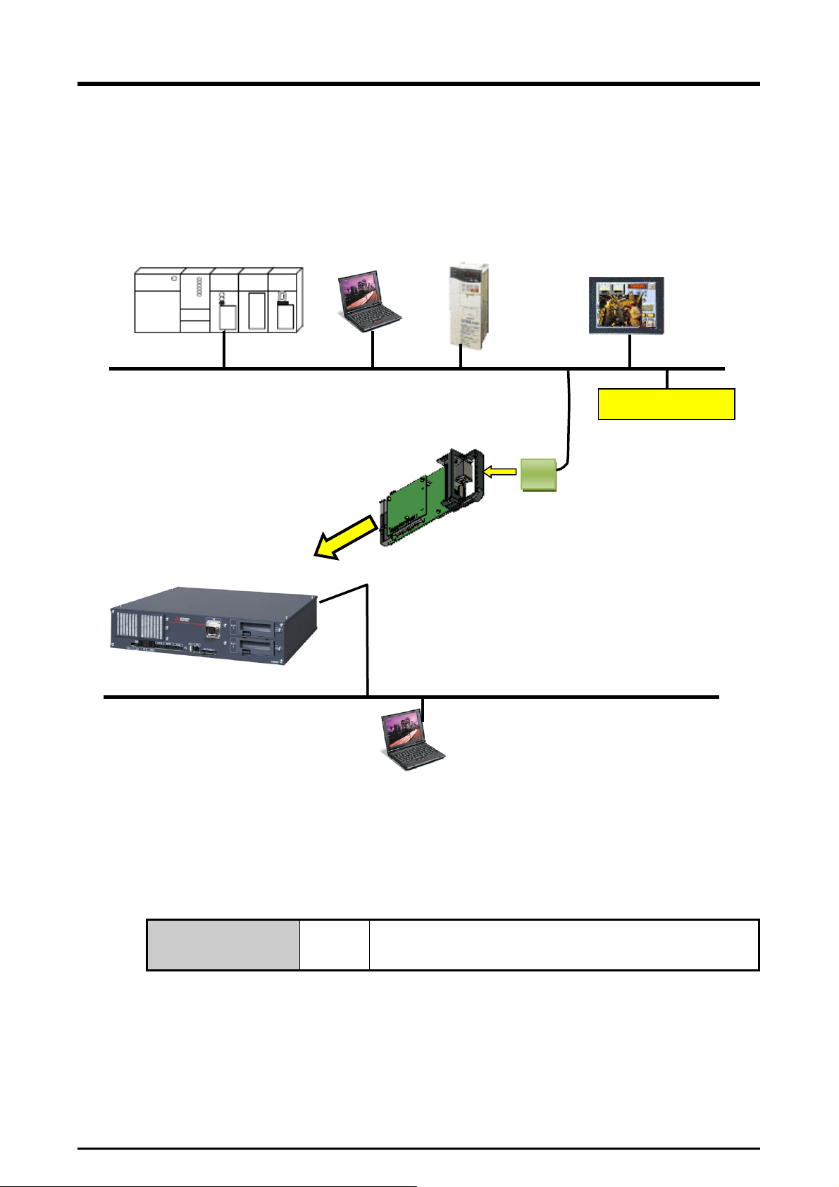
PLC
Inverter
Equipment by partner
manufacturer
Personal
computer
Network base card
Touch panel
Various communication lines
Ethernet
Personal
(RT ToolBox
Anybus-ComPactCom
CR800-D series
3. Features of Network Base Card (2F-DQ535)
3.1. What is a Network Base Card?
The network base card is an optional card for the robot controller.
By mounting a HMS's Anybus-CompactCom module on the card, various communication interfaces can
be realized.
controller
(Prepared by user)
module
(2F-DQ535)
Mountable to the
option slot 2
(Up to one card)
computer
3, etc.)
Figure 3-1 Example of configuring CC-Link IE Field with network base card
3.2. Mountable Modules
The modules which can be mounted on the network base card (2F-DQ535) are shown below.
Mountable module
3-4 What is a Network Base Card?
CC-Link IE Field module (AB6709)

3 Features of Network Base Card (2F-DQ535)
CC-Link IE
module
Standard
interface
Handling of data using I/O signals and
above.
Communication
with RT3
Communication with RT ToolBox3 by
Ethernet
Communication with other devices, such
as a network vision sensor, by Ethernet
Real-time
external control
Robot control from a personal computer,
etc.
Only cyclic transmission is supported. Transient transmission is not
CAUTION
3.3. Features when Module is Mounted
CC-Link IE Field
3.3.1. Features when CC-Link IE Field module is mounted
The following features are enabled when the CC-Link IE Field module is mounted on the 2F-DQ535 card.
(1) Connection
Connection to CC-Link IE Field Network is enabled.
CC-Link IE Field Network is an all-around field network based on Gigabit Ethernet that integrates the
controller-distributed control, I/O control, safety control, and motion control.
It enables flexible wiring with the topology such as star, line, or ring depending on the production line
or the layout of equipment or devices.
(2) Transmission style
IEE 802.3ab (1000BASE-T) Ethernet standard compatible, shielded twisted pair cable (Category 5e),
RJ-45 connector
(3) Data
Maximum 256-byte data communication using the real-time I/O signals (bit devices) and maximum
512-byte data communication using I/O registers (word devices) are available. The allocation can be
set with parameters described later.
Example 1) 128 bits (16 bytes) for input signals, 64 words (128 bytes) for input registers, 144 bytes in
total
128 bits (16 bytes) for output signals, 64 words (128 bytes) for output registers, 144 bytes
in total
Example 2) 2048 bits (256 bytes) for input signals, 0 words (0 bytes) for input registers, 256 bytes in
total
2048 bits (256 bytes) for output signals, 0 words (0 bytes) for output registers, 256 bytes
in total
(4) The table below shows differences of the functions available when the CC-link IE Field module is used
and those available with the standard Ethernet interface of the robot controller.
No. Function name Explanation
1 General-purpose I/O signal
2
TCP/IP
3 Data link
communication
4
I/O registers by Ethernet.
*For details of the data, refer to (3)
supported.
Although two types of transmission, cyclic transmission (periodic) and transient
transmission (non-periodic), are possible, this controller does not support the transient
transmission (as of April 2017).
Field
−
−
−
Ethernet
−
Features when Module is Mounted 3-5
3 Features of Network Base Card (2F-DQ535)
(Prepared by user)
(Red)
(Green)
Status
(Red) (Green)
Status
(Green)
Activity
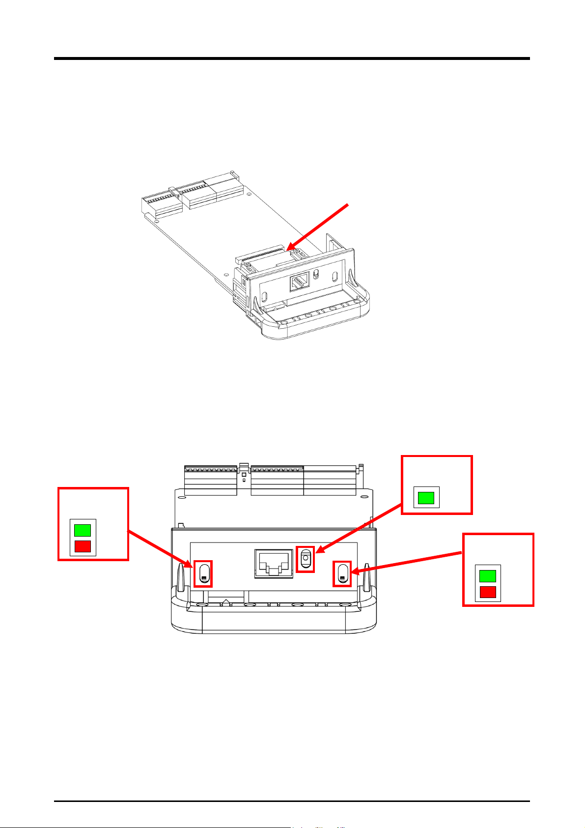
3.4. Hardware of the 2F-DQ535 Card
The 2F-DQ535 card hardware is explained in this section. An Anybus-CC module is mounted on the
network base card.
3.4.1. Card overview
Anybus-CC module
Figure 3-2 Overall view of 2F-DQ535 card
3.4.2. LED
There are three LEDs on the 2F-DQ535 card, and the operating state of the interface card can be
confirmed by each on/off.
* The shape and specifications of the Anybus-CC module vary depending on its type. (The following
figure shows an example of a CC-Link IE Field module.)
Network
LINK/
Module
3-6 Hardware of the 2F-DQ535 Card
Figure 3-3 Layout of LEDs
LED status
Details
Off
Power is not ON, or there is no IP address.
Green (on)
Online with one or more connection established (CIP Class 1 or 3).
Red (on)
IP address duplicate, FATAL error.
LED status
Details
Off
Power is not ON.
Green (on)
Controlling with RUN state scanner.
Red (on)
Serious error (EXCEPTION state, FATAL error, etc.).
It takes some time for the communication line to be established after the cable is
CAUTION
It takes some time for the communication line to be established after the robot
CAUTION
The meaning of each LED on, flash and off state is shown below.
Please confirm specifications of the HMS Co. about details.
Table 3-1
Details of Network Status LED
Details of Module Status LED
Description of LED
3 Features of Network Base Card (2F-DQ535)
controller power is turned ON.
It takes about one minute for the communication line to be established (for the Network Status LED to
turn on) after the robot controller power is turned ON. If automatic operation is started immediately
after turning the power ON, L6130 (network communication error) will occur. Wait for a short time
before starting automatic operation.
connected.
It takes about one minute for the communication line to be established (for the Network Status LED to
turn on) after the cable is connected to the Anybus-CC module on the DQ535 card.
Hardware of the 2F-DQ535 Card 3-7
 Loading...