

Page 1

AIR-COOLED ROOFTOP PACKAGED AIR CONDITIONERS
Series
COOLING ONLY
:
PR-5,8,10,15,20
HEAT PUMP
:
PRH-5,8,10,15,20
PRH-5,8,10,15,20-L
DATA BOOK
Page 2

- 1 -
CONTENTS
SAFETY FOR USE-----------------------------------------------------2
A COMPLETE LINE UP-----------------------------------------------4
FEATURES ---------------------------------------------------------------5
DESCRIPTIONS --------------------------------------------------------6
MECHANICAL SPECIFICATIONS----------------------------------6
TYPICAL INSTALLATION EXAMPLE------------------------------7
SPECIFICATIONS ------------------------------------------------------8
ELECTRICAL DATA ----------------------------------------------------9
CAPACITY TABLES---------------------------------------------------10
FAN PERFORMANCE-----------------------------------------------21
NC CURVES------------------------------------------------------------25
OUTLINE DIMENSIONS --------------------------------------------27
WIRING DIAGRAMS-------------------------------------------------29
ELECTRICAL OPERATION FLOW CHARTS------------------41
REFRIGERANT CYCLE SCHEMATICS-------------------------45
SAFETY & CONTROL DEVICES---------------------------------48
ACCESSORY AVAILABILITY --------------------------------------48
PHYSICAL DATA ------------------------------------------------------49
INSTALLATION --------------------------------------------------------51
INSTRUCTIONS FOR USE ----------------------------------------54
SPECIFICATION GUIDELINES -----------------------------------57
Specifications subject to change without notice.
Page 3
SAFETY FOR USE
- 2 -
fire may result. If you need to have the unit
The unit should not be installed by the user.
For installation, conduct the work correctly by
following the Installation Manual.
Install the unit on a spot sufficiently durable against
the unit weight.
All electric work must be performed by licensed
technician, according to local regulations and the
instructions given in this manual.
The units should be powered by dedicated power lines.
Use only the specified cables for wiring.
The connections must be made secured without
tension the terminals.
The unit should be installed according to the
instructions in order to minimize the risk of damage
from earthquakes, typhoons or strong winds.
The unit must be installed on stable, flat surface,
in a place where there is no accumulation of snow,
leaves or rubbish.
The unit should be installed in a location where air
and noise emitted by the unit will not disturb the
neighbors.
Never repair the unit, remodel or transfer it to
another site by yourself.
Use only the specified refrigerant (R-22) to charge
the refrigerant circuit.
Do not mix it with any other refrigerant and do not allow
air to remain in the circuit.
After completing installation work, make sure that
refrigerant gas has not leaked.
Take a proper measure to suppress the critical
concentration of refrigerant if leaked when
installing the unit in a small room.
The terminal block cover of unit must be firmly
attached to prevent entry of dust and moisture.
Use only optional parts authorised by Mitsubishi
Electric.
Before conducting installation work, please read this ''SAFETY FOR USE'' carefully
for
correct installation.
Since the caution items shown here contain important description relative to safety, please
observe them without fail.
After reading, please keep it with you together the Instruction Manual, and read it again at the
movement of the unit.
If the unit is installed improperly, explosion, water
leakage, electric shock or fire may be result.
Consult your dealer or specialist subcontractor for
repair and movement.
Improper installation may cause a fire, electrical shock
or water leakage.
Insufficient durability can cause an injury by the falling
down of unit.
Power lines with insufficient capacity or improper
electrical work may result in electric shock or fire.
Improper connection or fastening can cause a fire or
electrical shock.
Improper installation work can cause an injury by the
falling down of the unit.
If the unit is loosely mounted, it may fall, and cause injury.
If they are performed improperly, water leakage, electric
shock or
repaired or moved, consult your dealer.
Air enclosed in the circuit can cause high pressure resulting
in a rupture and other hazards.
If refrigerant gas has leaked and exposed to fan heater,
stove, oven and so on, it may generate noxious gases.
The limit density is made not to be exceeded even if the
refrigerant leaks by any chance.
You are necessary to ventilation measures to prevent
the accident. If the refrigerant leaks, hypoxia accident
may caused.
For the countermeasure to be taken, consult your
dealer.
Improper mounting of the cover cause electric shock or
fire.
If the accessories are installed improperly, water
leakage, electric shock or fire may result.
Ask your dealer or an authorised company to install
them.
Erroneous handling gives a high possibility to induce serious results such as
death or heavy injury.
Erroneous handling may induce serious injury depending on the situation.
Warning
Warning
Caution
Page 4
- 3 -
If the flammable gas can accumulate around the unit, an
explosion can occur.
The erroneous operation of air conditioner may be
induced by inverter equipment, independent power
device, medical equipment or communication
equipment.
While the erroneous operation of medical equipment or
communication equipment may caused by the air
conditioner.
As the use for the applications other than that
designed originally may result in the deterioration of the
quality. Consult your dealer in this regard.
Installing the unit at the following places may cause a
trouble, a place where much machine oil, salt sonnet,
humidity or dust, spa district, a place full of sulfur gas,
volatile gas, or corrosive gas, a place near high
frequency processing machine.
If the drain pipes are not properly insulated,
condensation will result and drip on ceiling, floor or other
possessions.
When the room humidity exceeds 80% or when the
drain pipe is clogged, water may drip from the indoor
unit. The outdoor unit produces condensation during the
heating operation.
Make sure to provide drainage around the outdoor unit if
such condensation is likely to cause damage.
Improper drain piping may cause water leakage and
damage to furniture or other possessions.
Do not connect the earth wire to gas pipe, city water
pipe, lightning rod or telephone earth wire.
Improper earth connection may cause electrical shock.
Failure to mount the electric leak breaker may cause
electrical shock.
Using a wire or a copper wire instead of proper capacity
of fuse can cause fire or trouble.
Other appliances connected to the same line could cause
an overload.
Otherwise, current leakage, overheating or fire may
occur.
The tighten or loosen the connections may cause generate
heat and cause fire.
The poor mounting of the panel or terminal cover may
cause the heat generation of the terminal connection,
a fire or electrical shock.
Otherwise electrical shock can be resulted.
When carrying in outdoor unit, be sure to support it at
four points.
Carrying in and lifting with 3-point support may make
outdoor unit unstable, resulting in a fall of it.
The unit should not be carried by only one person if it is
more than 20kg.
Some units use PP bands for packing.
Do not use any PP band for delivery purpose.
Do not touch the heat exchanger fins with your bear
hands.
Doing so may cut your hands.
Be sure to safely dispose the packaging materials.
Packaging materials, such as catches and other metal
or wooden parts, may cause stabs or other injuries.
Tear off and discard plastic packing bags so that
children will not play any of them.
If children play with a plastic bag which was not torn off,
it may cause a risk of suffocation.
If such defects are left uncorrected, the unit may fall and
cause personal injury or property damage.
Do not turn the main power switch OFF during seasons
of heavy use, doing so can result In failure.
Touching directly such part can cause a burn or
frostbite as it becomes high or low temperature
according to the refrigerant state.
Touching directly it may injure your hands.
You could be injured if you touch rotating, hot or highvoltage parts.
Dust may accumulate, and cause a failure.
Continuing the operation without eliminating the
emergency state may cause a machine trouble, fire, or
electrical shock.
Otherwise, water leakage or unit failure may occur.
If washed with water, electrical shock may be caused.
Do not wash the unit with water.
Refrain from installing the unit in an area where
flammable gas can accumulate around the unit.
When the unit is installed at telecommunication
centers or hospitals, take a proper provision
against noise.
For special use as for foods, animals/plants,
precision equipment or art objects, the applicability
should be confirmed beforehand.
Do not use the unit under a special atmosphere.
Thermal insulation of the drain pipes is necessary
prevent dew condensation.
The drain piping must process by surely,and insulate
the drain piping not to be dewy.
Install drain piping according to this Installation
Manual to ensure proper drainage.
Place thermal insulation on the pipes to prevent
condensation.
The unit must be properly earth connected.
When installing at a watery place, provide an
electric leak breaker.
Make sure that there is a main power switch.
Use breaker or fuse with proper capacity.
For the power lines, use standard cables of
sufficient current capacity.
When installing the power lines, do not apply
tension to the cables.
Arrange the configuration of wiring not to bring up
the panel and terminal cover, and fasten the panel
and terminal cover securely.
Do not handle the switch with wet hands.
Be very careful on handling the unit.
The base and attachments of the unit should be
periodically checked for looseness, cracks or other
damage.
Turn on the main power switch more than 6 hours
before starting operation.
Do not touch the compressor or refrigerant piping
without wearing glove on your hands.
Do not touch the metal edges inside the unit
without wearing glove on your hands.
Do not remove the front panel or the fan guard from
the unit when it is running.
Do not operate the air conditioner without the air
filter set place.
At emergency (if you smell something burning), stop
operation and turn the power source switch off.
After stopping operation, be sure to wait for five
minutes before turning off the main power switch.
Caution
Page 5
- 4 -
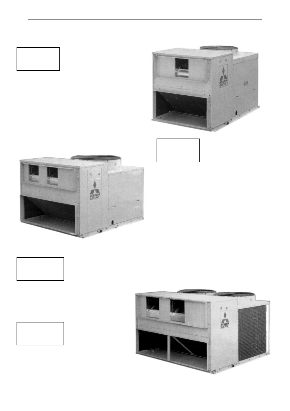
A COMPLETE LINE UP
Cooling capacity
14,000 kcal/h
55,600 BTU/h
16.3 kW
Cooling capacity
20,500 kcal/h
81,300 BTU/h
23.8 kW
PR-5YC
PRH-5YA
PRH-5YA-L
Cooling capacity
39,800 kcal/h
157,900 BTU/h
46.3 kW
Cooling capacity
52,300 kcal/h
207,500 BTU/h
60.8 kW
Cooling capacity
25,500 kcal/h
101,200 BTU/h
29.7 kW
Heatling capacity
19,800 kcal/h
78,600 BTU/h
23 kW
Heatling capacity
27,500 kcal/h
109,100 BTU/h
32 kW
Heatling capacity
39,100 kcal/h
155,100 BTU/h
45.5 kW
Heatling capacity
52,600 kcal/h
208,700 BTU/h
61.2 kW
Heatling capacity
13,000 kcal/h
51,600 BTU/h
15.1 kW
PR-8YC
PRH-8YA
PRH-8YA-L
PR-10YC
PRH-10YA
PRH-10YA-L
PR-15YC
PRH-15YA
PRH-15YA-L
PR-20YC
PRH-20YA
PRH-20YA-L
(PRH ONLY)
(PRH ONLY)
(PRH ONLY)
(PRH ONLY)
(PRH ONLY)
Page 6

FEATURES
- 5 -
High Sensible Cooling Capacity
The sensible cooling capacity has been significantly
improved through optimized heat exchanger design.
Comfort Heating
The PRH series are designed to provide effective heating
even when the outside temperature is down to 0˚C. The
PRH-L series are designed to provide effective heating
even when the outside temperature is down to -10˚C.In
addition, the twin circuit models, PRH-15,20YA,
PRH-15,20YA-L are provided with control features that
prevents both refrigeration circuits defrosting at the same
time. This ensures constant comfort conditions during
defrost and varying loads.
Highly Efficient Operation
The EER (Energy Efficiency Ratio) on these models is
greatly improved by revised design specifications and by
being manufactured stringently to Mitsubishi Electric
high quality standards.
Flexibility of Supply Air Delivery
All series feature belt driven Supply Air fans enabling
accurate matching of actual airflow rates to the specified
quantities. Accurate commissioning is assisted by the
capability to exchange pulleys and belts if necessary to
achieve the desired air balance.
Low Ambient Cooling
In applications with relatively high internal loads,
there may be a requirement for all series to operate
on cooling at low ambient conditions. An optional
accessory is available to maintain the refrigeration
circuit in balance at outdoor temperatures as low as
0˚C (PRH only).In case of PR,PRH-L is -5˚C.
Please consult your local Mitsubishi Electric Sales
office for application advice on this accessory.
Wide Electrical Control Capability
All series may be ordered in either of two control
configurations.
The factory standard is for provision of a 24 volt
terminal block to enable a field wired control of the
contractors choice to be connected.
Alternatively, for models PR-5-10YC,PRH-5-10YA,
PRH-5-10YA-L the intelligent "K" series remote
control system may be ordered. The K control
utilizes a microprocessor and includes liquid crystal
display with touch pad for adjustment of control
parameters.
These options give the flexibility to enable
connection to Building Management Systems,
smoke spill cycles, economy cycles, remote
monitoring etc.
Please consult your local Mitsubishi Electric Sales
office for application advice on these controls.
Labor Saving Installation
Because of the single unit configuration, all
refrigeration work can be omitted. The unit operation
can commence immediately after connection to the
power supply, drain piping, ducting and control
system.
Page 7

MECHANICAL SPECIFICATIONS
- 6-
General
All units are factory assembled, piped, internally
wired and fully charged with R-22. They are also
tested and checked under a strict quality control
system in the factory. All units are designed for
outdoor rooftop or ground level installation. Exterior
surfaces of all units are phosphatized, zinc-coated
steel with acrylic resin primer and ivory white baked
enamel finish.
Condenser Coils
Unnecessary power input due to higher
discharge pressure is avoided by high
performance designs of cross-finned coils.
Condenser coils are made of 9.52mm OD,
0.35mm thick seamless copper tubes
mechanically bonded to 0.12mm thick aluminium
plate fins. Each coil is factory pressure and leak
tested at 3.3MPa.
Refrigeration Controls
Refrigeration controls include condenser fan,
evaporator fan and compressor contactor. Each
circuit of the unit has a separate set of refrigeration
controls. PR, PRH,PRH-L-15,20 units have two
independent circuits.
Evaporator Fans
Belt-drive, forward curved, centrifugal type fans
made of galvanized steel are used to deliver an
accurate airflow at low noise level.
Compressors
All units have high efficiency type hermetic line
starting compressors. Compressors are equipped
with thermal overload protector, overcurrent relay
and high pressure protection controls. Crankcase
heaters are standard .
Condenser Fan
This direct-drive propeller fan is dynamically
balanced, to ensure smooth airflow. A weatherproof three-phase squirrel cage induction motor
is used to drive the condenser fan.
Evaporator Coils
Highly efficient cross-finned coils are applied to
provide a larger cooling capacity with low air speed
on the coil. Coils are made of 9.52mm OD and
0.35mm thick seamless copper tubing
mechanically bonded to 0.12mm thick aluminium
fins and are factory leak tested at a pressure of
3.3MPa. They are provided with strainers attached
to the capillary tubes to further ensure a clean
system.
DESCRIPTIONS
MITSUBISHI ELECTRIC Rooftop Air Conditioners
Series PR,PRH,RPH-L are available in a wide
range of sizes and models to enable the designer
to select the best model for each application.
The complete range has been designed for
outdoor installation, and the units are provided with
the latest technological features to ensure
economical, reliable and comfortable ducted type
air conditioning.
All series units are completely assembled, wired
and strictly tested at the factory. They consist of a
compressors, air-cooled condensers, evaporator
fans, condenser fans and auxiliary and control
equipment, completely packaged in a water-proof
enclosure.
With the development of all series demands for
such features as light weight, compactness,
increased capacity, appropriate static pressure , air
flow control, and having flexibility of inter-facing
energy saving electronic controls Mitsubishi
Electric have met market expectations.
Page 8
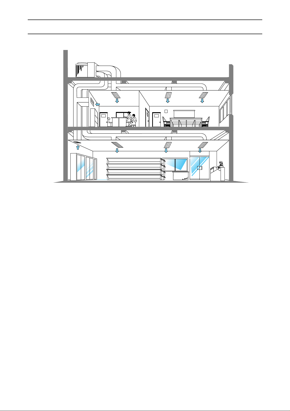
TYPICAL INSTALLATION EXAMPLE
- 7-
PR
PRH
PRH-L
Page 9
- 8 -
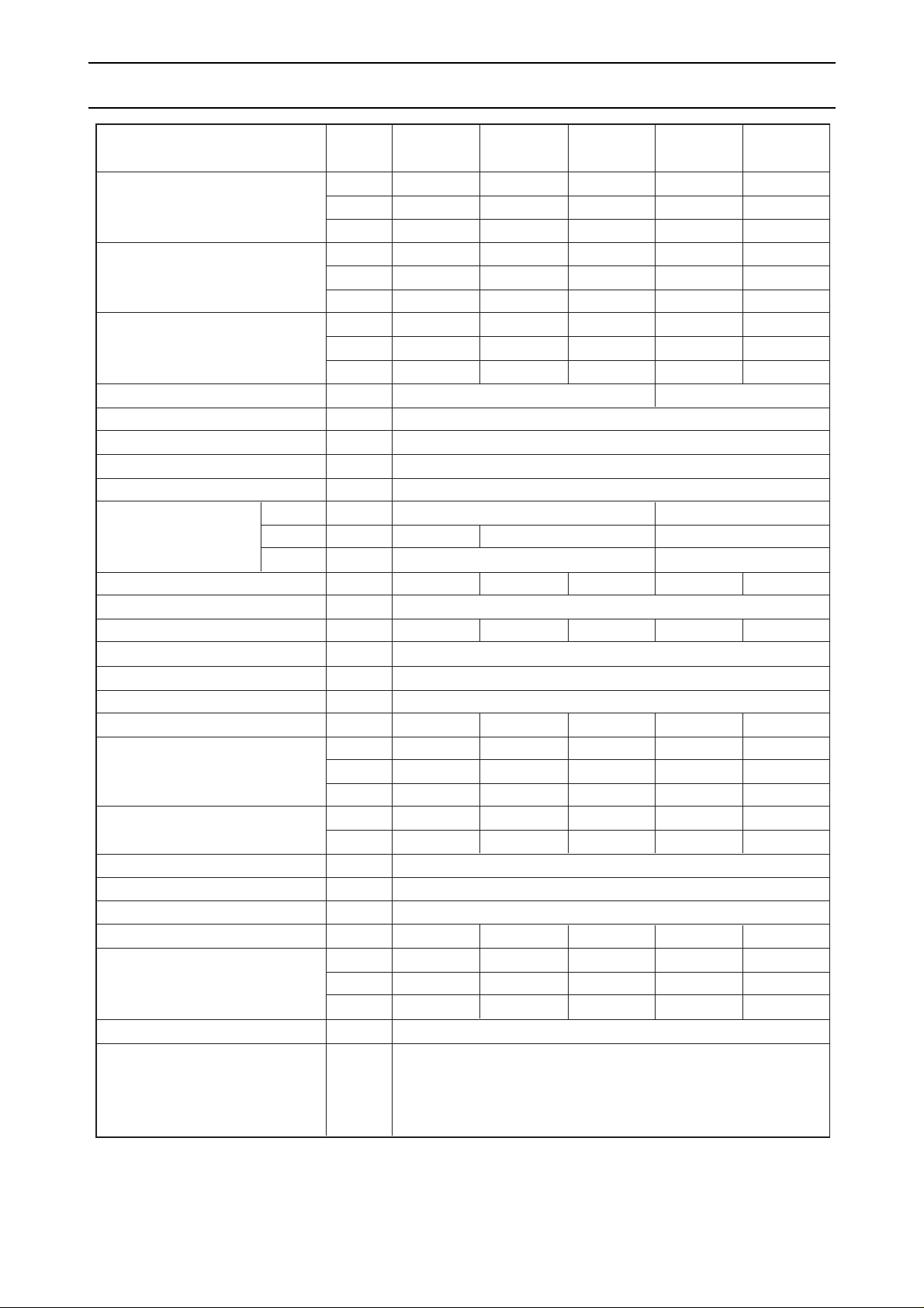
SPECIFICATIONS
ITEM
PR-5YC
PRH-5YA
PRH-5YA-L
PR-8YC
PRH-8YA
PRH-8YA-L
PR-10YC
PRH-10YA
PRH-10YA-L
PR-15YC
PRH-15YA
PRH-15YA-L
PR-20YC
PRH-20YA
PRH-20YA-L
16.3 23.8 29.7 46.3 60.8
TOTAL COOLING CAPACITY
BTU/h 55,600 81,300 101,200 157,900 207,500
(GROSS)
kcal/h 14,000 20,500 25,500 39,800 52,300
kW
kW
13 19.7 25.3 38.4 50.2
SENSIBLE COOLING CAPACITY
BTU/h 44,400 67,100 86,500 130,900 171,400
(GROSS)
kcal/h 11,200 16,900 21,800 33,000 43,200
kW 15.1 23 32 45.5 61.2
TOTAL HEATING CAPACITY
BTU/h 51,600 78,600 109,100 155,100 208,700
(GROSS)
(PRH-YA,PRH-YA-L ONLY)
kcal/h 13,000 19,800 27,500 39,100 52,600
CAPACITY STEPS % 0-100 0-50-100
REFRIGERANT R22 (FACTORY CHARGED)
REFRIGERANT CONTROL CAPILLARY TUBE
EXTERNAR FINISH ACRYLIC RESIN COATING
COLOR (MUNSELL NO.) MUNSELL 5Y8/1
HEIGHT mm 1,000 1,200
DIMENSION
WIDTH mm 1,000 1,300 1,990
DEPTH mm 1,600 1,840
NET WEIGHT kg 29 9 39 3 41 3 69 8 72 9
COMPRESSOR HERMETIC LINE START (RECIPROCATING)
MOTOR OUTPUT kW 3.73 5.6 7.5 2
XX
XX
XX
XX
XX
5.6 2 7.5
INDOOR COIL CROSS FIN COIL
FAN CENTRIFUGAL (GALVANIZED STEEL) - BELT DRIVE
FAN MOTOR THREE PHASE CAGE INDUCTION MOTOR
FAN MOTOR OUTPUT kW 0.75 1.1 1.5 2.2 3
CM M 54 84 100 168 190
NOMINAL AIR FLOW CFM 1,907 2,967 3,532 5,934 6,711
L/ S 900 1,400 1,660 2,800 3,160
EXTERNAL STATIC mmAq 10 10 10 20 20
PRESSURE Pa 100 100 100 200 200
OUTDOOR COIL CROSS FIN COIL
FAN PROPELLER - DIRECT DRIVE
FAN MOTOR THREE PHASE CAGE INDUCTION MOTOR
FAN MOTOR OUTPUT kW 0.15 0.35 0.35 2 0.35 2 0.35
CMM 95 185 185 2 185 2 185
NOMINAL AIR FLOW
C F M 3,355 6,534 6,534 2 6,534 2 6,534
L/ S 1,583 3,083 3,083 2 3,083 2 3,083
DRAIN CONNECTION mm 25.4
HIGH PRESSURE SWITCH,FUSE
PROTECTION DEVICES
OVER CURRENT RELAY (COMP. & INDOOR FAN,OUTDOOR FAN )
INTERNAL THERMOSTAT (COMP. & OUTDOOR FAN )
ANTI SHORT-CYCLE TIMER, FREEZE & FROST PROTECTOR
NOTE 1. NOMINAL COOLING & HEATING CAPACITIES ARE BASED FOLLOWING CONDITIONS.
COOLING : INDOOR:27˚CDB, 19˚C WB ; OUTDOOR:35˚CDB.
HEATING : INDOOR:21˚CDB ; OUTDOOR:7DB, 6˚C WB.
2. CAPACITIES ARE GROSS CAPACITIES WHICH DO NOT INCLUDE A DEDUCTION FOR EVAPORATOR
FAN MOTOR HEAT.
Page 10
- 9 -
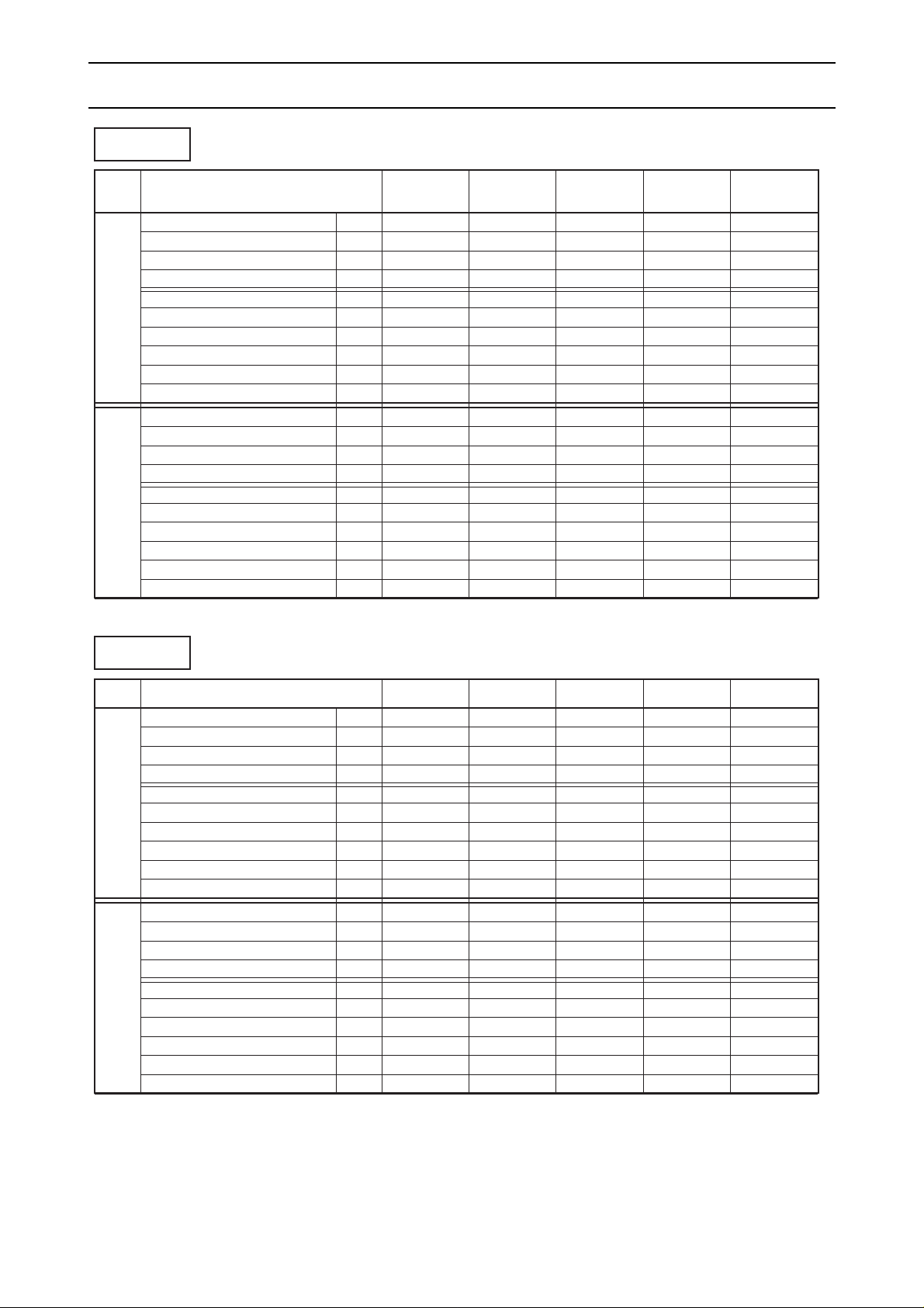
ELECTRICAL DATA
Heating
VOLT ITEM
PR-5YC
PRH-5YA
PRH-5YA-L
PR-8YC
PRH-8YA
PRH-8YA-L
PR-10YC
PRH-10YA
PRH-10YA-L
PR-15YC
PRH-15YA
PRH-15YA-L
PR-20YC
PRH-20YA
PRH-20YA-L
TOTAL INPUT kW 5.4 8.3 11.4 16.8 22.7
TOTAL RUN CURRENT A 10.3 15.9 20.2 30.8 39.1
POWER FACTOR % 73 73 79 76 81
START CURRENT A 62 87 100 11 5 13 5
415V COMPRESSOR INPUT kW 3.92 6.46 9.22 2 X 6.55 2 X 9.30
RUN CURRENT A 7.44 11.70 15.62 2 X 11.74 2 X 15.22
I/D FAN INPUT kW 1.24 1.30 1.64 2.62 3.02
RUN CURRENT A 2.26 2.90 3.28 4.72 6.06
O/D FAN INPUT kW 0.24 0.54 0.54 2 X 0.54 2 X 0.54
RUN CURRENT A 0.6 1.3 1.3 2 X 1.3 2 X 1.3
TOTAL INPUT kW 5.4 8.3 11.4 16.8 22.7
TOTAL RUN CURRENT A 11.2 17.3 21.9 33.6 42.6
POWER FACTOR % 73 73 79 76 81
START CURRENT A 68 95 109 12 6 14 7
380V COMPRESSOR INPUT kW 3.92 6.46 9.22 2 X 6.55 2 X 9.30
RUN CURRENT A 8.06 12.71 16.90 2 X 12.80 2 X 16.57
I/D FAN INPUT kW 1.24 1.30 1.64 2.62 3.02
RUN CURRENT A 2.48 3.17 3.58 5.16 6.62
O/D FAN INPUT kW 0.24 0.54 0.54 2 X 0.54 2 X 0.54
RUN CURRENT A 0.66 1.42 1.42 2 X 1.42 2 X 1.42
Cooling
VOLT ITEM
PRH-5YA
PRH-5YA-L
PRH-8YA
PRH-8YA-L
PRH-10YA
PRH-10YA-L
PRH-15YA
PRH-15YA-L
PRH-20YA
PRH-20YA-L
TOTAL INPUT
kW 4.8 7.0 9.6 14.4 19.3
TOTAL RUN CURRENT
A 9.8 14.1 18.2 27.2 34.8
POWER FACTOR
%6869737477
START CURRENT
A 62 87 100 111 131
415V COMPRESSOR INPUT kW 3.32 5.16 7.42 2 X 5.35 2 X 7.60
RUN CURRENT A 6.94 9.90 13.62 2 X 9.94 2 X 1 3 . 0 7
I/D FAN INPUT kW 1.24 1.30 1.64 2.62 3.02
RUN CURRENT A 2.26 2.90 3.28 4.72 6.06
O/D FAN INPUT kW 0.24 0.54 0.54 2 X 0.54 2 X 0.54
RUN CURRENT A 0.6 1.3 1.3 2 X 1.3 2 X 1.3
TOTAL INPUT
kW 4.8 7.0 9.6 14.4 19.3
TOTAL RUN CURRENT
A 10.7 15.4 20.0 29.6 38.1
POWER FACTOR
%6869737477
START CURRENT
A 68 95 109 121 143
380V COMPRESSOR INPUT kW 3.32 5.16 7.42 2 X 5.35 2 X 7.60
RUN CURRENT A 7.56 10.81 15.00 2 X 10.8 2 X 14.32
I/D FAN INPUT kW 1.24 1.30 1.64 2.62 3.02
RUN CURRENT A 2.48 3.17 3.58 5.16 6.62
O/D FAN INPUT kW 0.24 0.54 0.54 2 X 0.54 2 X 0.54
RUN CURRENT A 0.66 1.42 1.42 2 X 1.42 2 X 1.42
(PRH,PRH-L Only)
Page 11
OUTDOOR DB ˚C
INDOOR INDOOR 20.0 25.0 30.0 35.0 40.0 46.0
DB ˚ C WB ˚C Q kW SHC kW S H F T/I kW Q kW SHC kW SHF T/I kW Q kW SHC kW SHF T/I kW Q kW SHC kW SHF T/I kW Q kW SHC kW SHF T/I kW Q kW SHC kW SHF T/I kW
15 16.4 11.3 0.69 4.5 15.8 11.1 0.70 4.7 15.2 10.8 0.71 4.9 14.5 10.4 0.72 5.1 13.8 10.1 0.73 5.4 13.0 9.8 0.75 5.7
20 16 16.9 10.3 0.61 4.6 16.3 10.1 0.62 4.8 15.6 9.8 0.63 5.0 15.0 9.6 0.64 5.2 14.2 9.2 0.65 5.5 13.3 8.9 0.67 5.8
17 17.4 9.4 0.54 4.6 16.8 9.1 0.54 4.8 16.1 8.9 0.55 5.0 15.4 8.5 0.55 5.3 14.7 8.2 0.56 5.5 13.7 7.8 0.57 5.8
15 16.4 13.1 0.80 4.5 15.8 12.8 0.81 4.7 15.2 12.5 0.82 4.9 14.5 12.2 0.84 5.1 13.8 11.9 0.86 5.4 13.0 11.6 0.89 5.7
16 16.9 12.2 0.72 4.6 16.3 11.9 0.73 4.8 15.6 11.5 0.74 5.0 15.0 11.4 0.76 5.2 14.2 11.1 0.78 5.5 13.3 10.6 0.80 5.8
22 17 17.4 11.1 0.64 4.6 16.8 10.9 0.65 4.8 16.1 10.6 0.66 5.0 15.4 10.3 0.67 5.3 14.7 10.1 0.69 5.5 13.7 9.7 0.71 5.8
18 17.9 10.2 0.57 4.7 17.3 10.0 0.58 4.9 16.6 9.8 0.59 5.1 15.9 9.4 0.59 5.3 15.1 9.1 0.60 5.6 14.2 8.8 0.62 5.9
19 18.5 9.4 0.51 4.7 17.8 9.1 0.51 4.9 17.1 8.9 0.52 5.2 16.3 8.5 0.52 5.4 15.6 8.3 0.53 5.7 14.6 7.9 0.54 6.0
16 16.9 14.0 0.83 4.6 16.3 13.7 0.84 4.8 15.6 13.4 0.86 5.0 15.0 13.2 0.88 5.2 14.2 12.8 0.90 5.5 13.3 12.5 0.94 5.8
17 17.4 13.1 0.75 4.6 16.8 12.8 0.76 4.8 16.1 12.4 0.77 5.0 15.4 12.2 0.79 5.3 14.7 11.9 0.81 5.5 13.7 11.5 0.84 5.8
24 18 17.9 12.2 0.68 4.7 17.3 11.9 0.69 4.9 16.6 11.6 0.70 5.1 15.9 11.3 0.71 5.3 15.1 11.0 0.73 5.6 14.2 10.7 0.75 5.9
19 18.5 11.1 0.60 4.7 17.8 10.9 0.61 4.9 17.1 10.6 0.62 5.2 16.3 10.3 0.63 5.4 15.6 10.0 0.64 5.7 14.6 9.6 0.66 6.0
20 19.0 10.1 0.53 4.8 18.3 9.7 0.53 5.0 17.6 9.5 0.54 5.2 16.8 9.2 0.55 5.5 16.0 9.0 0.56 5.8 15.0 8.6 0.57 6.1
21 19.5 9.2 0.47 4.8 18.8 8.8 0.47 5.1 18.0 8.6 0.48 5.3 17.3 8.5 0.49 5.6 16.4 8.2 0.50 5.9 15.4 7.9 0.51 6.2
18 17.9 14.0 0.78 4.7 17.3 13.7 0.79 4.9 16.6 13.4 0.81 5.1 15.9 13.2 0.83 5.3 15.1 12.8 0.85 5.6 14.2 12.5 0.88 5.9
19 18.5 13.0 0.70 4.7 17.8 12.6 0.71 4.9 17.1 12.3 0.72 5.2 16.3 12.1 0.74 5.4 15.6 11.9 0.76 5.7 14.6 11.4 0.78 6.0
26 20 19.0 12.0 0.63 4.8 18.3 11.7 0.64 5.0 17.6 11.4 0.65 5.2 16.8 11.1 0.66 5.5 16.0 10.7 0.67 5.8 15.0 10.4 0.69 6.1
21 19.5 10.9 0.56 4.8 18.8 10.7 0.57 5.1 18.0 10.4 0.58 5.3 17.3 10.2 0.59 5.6 16.4 9.8 0.60 5.9 15.4 9.5 0.62 6.2
22 20.1 10.1 0.50 4.9 19.3 9.7 0.50 5.1 18.5 9.4 0.51 5.4 17.7 9.2 0.52 5.7 16.9 9.0 0.53 6.0 15.9 8.6 0.54 6.3
23 20.7 9.1 0.44 4.9 19.9 8.8 0.44 5.2 19.1 8.6 0.45 5.5 18.3 8.2 0.45 5.8 17.4 8.0 0.46 6.1 16.4 7.5 0.46 6.4
19 18.5 14.8 0.80 4.7 17.8 14.4 0.81 4.9 17.1 14.2 0.83 5.2 16.3 13.9 0.85 5.4 15.6 13.6 0.87 5.7 14.6 13.1 0.90 6.0
20 19.0 13.7 0.72 4.8 18.3 13.4 0.73 5.0 17.6 13.2 0.75 5.2 16.8 12.8 0.76 5.5 16.0 12.5 0.78 5.8 15.0 12.2 0.81 6.1
28 21 19.5 12.9 0.66 4.8 18.8 12.6 0.67 5.1 18.0 12.2 0.68 5.3 17.3 11.9 0.69 5.6 16.4 11.6 0.71 5.9 15.4 11.2 0.73 6.2
22 20.1 11.9 0.59 4.9 19.3 11.6 0.60 5.1 18.5 11.3 0.61 5.4 17.7 11.0 0.62 5.7 16.9 10.6 0.63 6.0 15.9 10.3 0.65 6.3
23 20.7 11.0 0.53 4.9 19.9 10.5 0.53 5.2 19.1 10.3 0.54 5.5 18.3 10.1 0.55 5.8 17.4 9.7 0.56 6.1 16.4 9.3 0.57 6.4
24 21.4 10.1 0.47 5.0 20.6 9.7 0.47 5.3 19.8 9.5 0.48 5.6 18.9 9.1 0.48 5.9 18.0 8.8 0.49 6.2 16.8 8.4 0.50 6.5
20 19.0 15.6 0.82 4.8 18.3 15.2 0.83 5.0 17.6 15.0 0.85 5.2 16.8 14.6 0.87 5.5 16.0 14.2 0.89 5.8 15.0 14.0 0.93 6.1
21 19.5 14.6 0.75 4.8 18.8 14.3 0.76 5.1 18.0 14.0 0.78 5.3 17.3 13.8 0.80 5.6 16.4 13.4 0.82 5.9 15.4 13.1 0.85 6.23022 20.1 13.7 0.68 4.9 19.3 13.3 0.69 5.1 18.5 13.0 0.70 5.4 17.7 12.7 0.72 5.7 16.9 12.5 0.74 6.0 15.9 12.1 0.76 6.3
23 20.7 12.6 0.61 4.9 19.9 12.3 0.62 5.2 19.1 12.0 0.63 5.5 18.3 11.9 0.65 5.8 17.4 11.7 0.67 6.1 16.4 11.3 0.69 6.4
24 21.4 11.8 0.55 5.0 20.6 11.5 0.56 5.3 19.8 11.3 0.57 5.6 18.9 11.0 0.58 5.9 18.0 10.6 0.59 6.2 16.8 10.2 0.61 6.5
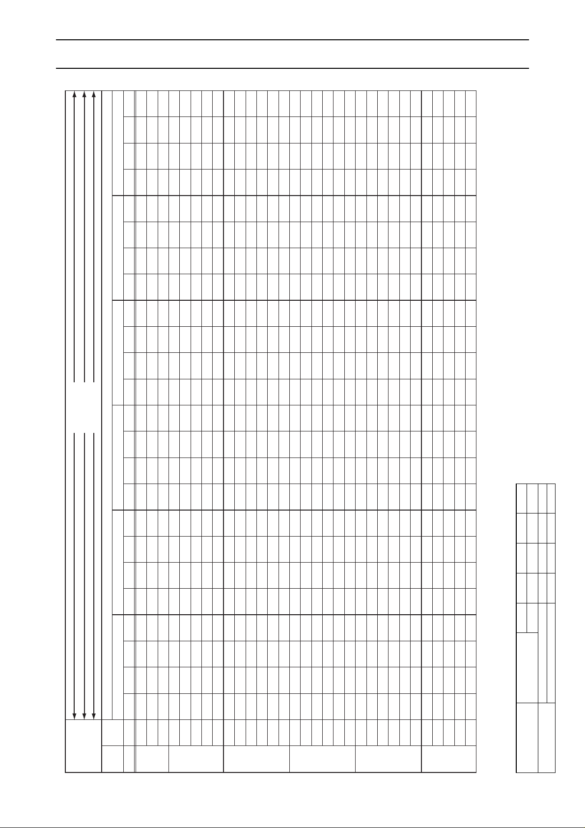
PR-5YC
PRH-5YA
PRH-5YA-L
AIR VOLUME
CMM 45 50 55 60
L/S 750 830 920 1,000
COOLING
CAPACITY 0.975 0.988 1.0 1.013
TOTAL INPUT 0.987 0.994 1.0 1.005
OPERATION
RANGE
PR-5YC
PRH-5YA-L
PRH-5YA
- 10 -
CAPACITY TABLES
Cooling Capacity (Nominal Air Flow):PR-5YC, PRH-5YA, PRH-5YA-L
Note1. * Q :COOLING CAPACITY SHC:SENSIBLE HEAT CAPACITY T/I:TOTAL INPUT
Factor for Various Air Flow
Page 12
OPERATION
RANGE
OPERATION
RANGE
OPERATION
RANGE
OUTDOOR DB
˚C
INDOOR INDOOR
-5.0
0.0 5.0 10.0 15.0
DB
˚C
WB
˚C
Q kW SHC kW SH F T/I kW
Q kW SHC kW SH F T/I kW Q kW SHC kW SHF T/I kW Q kW SHC kW SH F T/I kW Q kW SHC kW SHF T/I kW
15
18.0 12.1 0.67 4.0
17.9 12.0 0.67 4.0 17.7 12.0 0.68 4.1 17.4 11.8 0.68 4.2 16.9 11.7 0.69 4.3
20 16
18.5 11.1 0.60 4.0
18.4 11.0 0.60 4.0 18.2 10.9 0.60 4.1 17.9 10.9 0.61 4.2 17.4 10.6 0.61 4.4
17
19.1 10.1 0.53 4.1
19.0 10.1 0.53 4.1 18.7 9.9 0.53 4.2 18.3 9.7 0.53 4.3 17.9 9.7 0.54 4.4
15
18.0 13.9 0.77 4.0
17.9 13.8 0.77 4.0 17.7 13.8 0.78 4.1 17.4 13.6 0.78 4.2 16.9 13.4 0.79 4.3
16
18.5 13.0 0.70 4.0
18.4 12.9 0.70 4.0 18.2 12.9 0.71 4.1 17.9 12.7 0.71 4.2 17.4 12.5 0.72 4.4
22 17
19.1 12.0 0.63 4.1
19.0 12.0 0.63 4.1 18.7 11.8 0.63 4.2 18.3 11.7 0.64 4.3 17.9 11.5 0.64 4.4
18
19.7 11.0 0.56 4.1
19.6 11.0 0.56 4.1 19.3 10.8 0.56 4.2 18.9 10.8 0.57 4.3 18.5 10.5 0.57 4.5
19
20.3 10.2 0.50 4.2
20.2 10.1 0.50 4.2 19.9 10.0 0.50 4.3 19.5 9.8 0.50 4.4 19.1 9.7 0.51 4.5
16
18.5 14.8 0.80 4.0
18.4 14.7 0.80 4.0 18.2 14.7 0.81 4.1 17.9 14.5 0.81 4.2 17.4 14.3 0.82 4.4
17
19.1 13.9 0.73 4.1
19.0 13.9 0.73 4.1 18.7 13.8 0.74 4.2 18.3 13.5 0.74 4.3 17.9 13.4 0.75 4.4
24 18
19.7 13.0 0.66 4.1
19.6 12.9 0.66 4.1 19.3 12.9 0.67 4.2 18.9 12.7 0.67 4.3 18.5 12.6 0.68 4.5
19
20.3 12.0 0.59 4.2
20.2 11.9 0.59 4.2 19.9 11.7 0.59 4.3 19.5 11.7 0.60 4.4 19.1 11.5 0.60 4.5
20
20.9 10.9 0.52 4.2
20.8 10.8 0.52 4.2 20.5 10.7 0.52 4.3 20.1 10.7 0.53 4.4 19.6 10.4 0.53 4.6
21
21.6 9.9 0.46 4.3
21.5 9.9 0.46 4.3 21.2 9.8 0.46 4.4 20.8 9.8 0.47 4.5 20.2 9.5 0.47 4.6
18
19.7 14.8 0.75 4.1
19.6 14.7 0.75 4.1 19.3 14.7 0.76 4.2 18.9 14.4 0.76 4.3 18.5 14.2 0.77 4.5
19
20.3 13.8 0.68 4.2
20.2 13.7 0.68 4.2 19.9 13.7 0.69 4.3 19.5 13.5 0.69 4.4 19.1 13.4 0.70 4.5
26 20
20.9 12.7 0.61 4.2
20.8 12.7 0.61 4.2 20.5 12.7 0.62 4.3 20.1 12.5 0.62 4.4 19.6 12.3 0.63 4.6
21
21.6 11.9 0.55 4.3
21.5 11.8 0.55 4.3 21.2 11.7 0.55 4.4 20.8 11.6 0.56 4.5 20.2 11.3 0.56 4.6
22
22.3 10.9 0.49 4.3
22.1 10.8 0.49 4.3 21.8 10.7 0.49 4.4 21.4 10.7 0.50 4.5 20.8 10.4 0.50 4.7
23
23.0 9.9 0.43 4.4
22.8 9.8 0.43 4.4 22.5 9.7 0.43 4.5 22.0 9.7 0.44 4.6 21.4 9.4 0.44 4.7
19
20.3 15.6 0.77 4.2
20.2 15.6 0.77 4.2 19.9 15.5 0.78 4.3 19.5 15.2 0.78 4.4 19.1 15.1 0.79 4.5
20
20.9 14.6 0.70 4.2
20.8 14.6 0.70 4.2 20.5 14.6 0.71 4.3 20.1 14.3 0.71 4.4 19.6 14.1 0.72 4.6
28 21
21.6 13.6 0.63 4.3
21.5 13.5 0.63 4.3 21.2 13.6 0.64 4.4 20.8 13.3 0.64 4.5 20.2 13.1 0.65 4.6
22
22.3 12.7 0.57 4.3
22.1 12.6 0.57 4.3 21.8 12.6 0.58 4.4 21.4 12.4 0.58 4.5 20.8 12.3 0.59 4.7
23
23.0 11.7 0.51 4.4
22.8 11.6 0.51 4.4 22.5 11.5 0.51 4.5 22.0 11.4 0.52 4.6 21.4 11.1 0.52 4.7
24
23.7 10.7 0.45 4.4
23.5 10.6 0.45 4.4 23.2 10.4 0.45 4.5 22.7 10.4 0.46 4.6 22.1 10.2 0.46 4.8
20
20.9 16.3 0.78 4.2
20.8 16.2 0.78 4.2 20.5 16.2 0.79 4.3 20.1 16.1 0.80 4.4 19.6 15.9 0.81 4.6
21
21.6 15.3 0.71 4.3
21.5 15.3 0.71 4.3 21.2 15.3 0.72 4.4 20.8 15.2 0.73 4.5 20.2 14.9 0.74 4.6
30 22
22.3 14.5 0.65 4.3
22.1 12.2 0.55 4.3 21.8 14.4 0.66 4.4 21.4 14.1 0.66 4.5 20.8 13.9 0.67 4.7
23
23.0 13.6 0.59 4.4
22.8 13.5 0.59 4.4 22.5 13.5 0.60 4.5 22.0 13.2 0.60 4.6 21.4 13.1 0.61 4.7
24
23.7 12.6 0.53 4.4
23.5 12.5 0.53 4.4 23.2 12.5 0.54 4.5 22.7 12.3 0.54 4.6 22.1 12.2 0.55 4.8
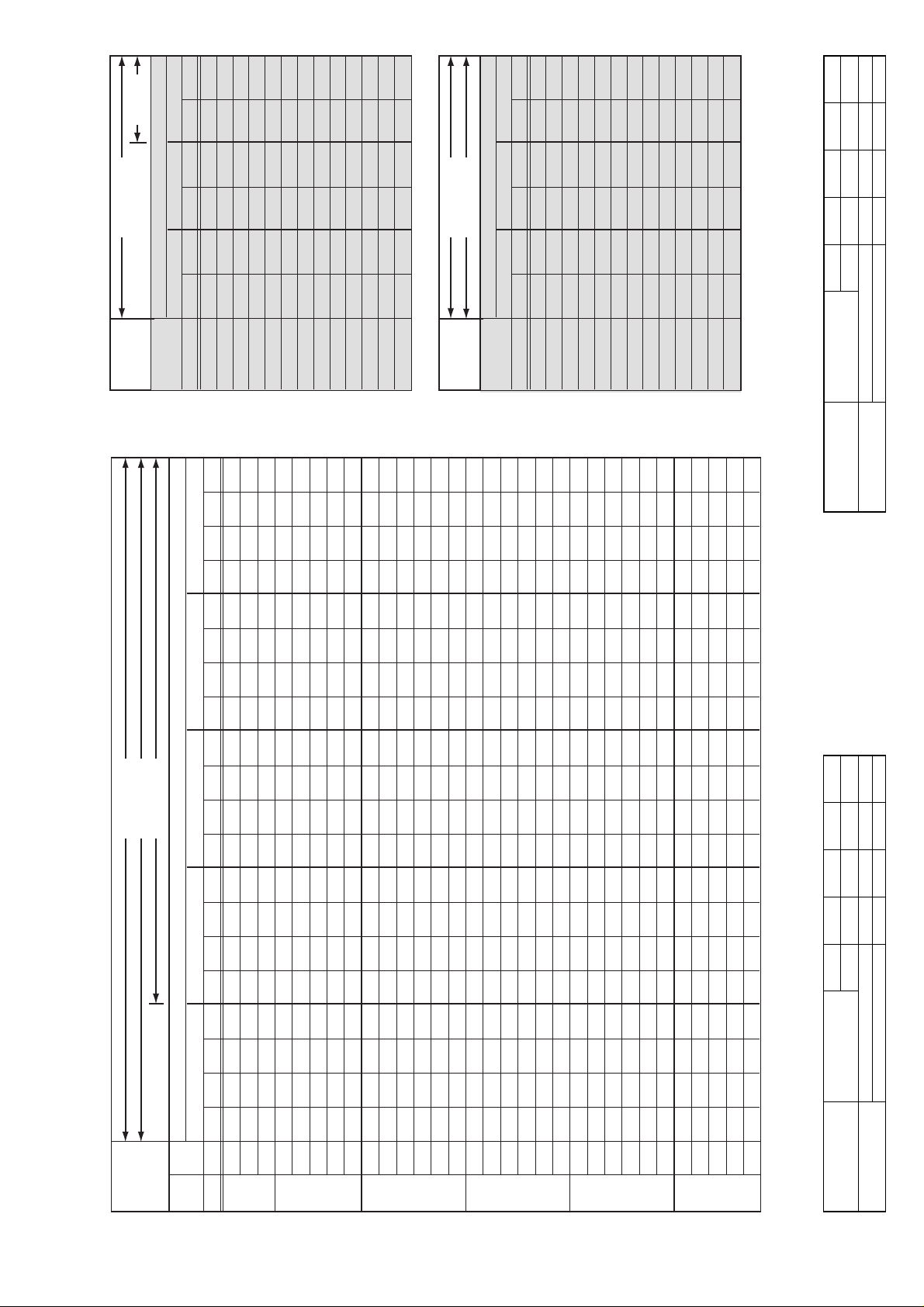
PR-5YC
PRH-5YA
PRH-5YA-L
AIR VOLUME
CMM 45 50 55 60
L/S 750 830 920 1,000
COOLING
CAPACITY 0.975 0.988 1.0 1.013
TOTAL INPUT 0.987 0.994 1.0 1.005
PRH-5YA
PRH-5YA-L
AIR VOLUME
CMM 45 50 55 60
L/S 750 830 920 1,000
HEATING
CAPACITY
0.975 0.988 1.0 1.008
TOTAL INPUT
1.035 1.018 1.0 0.990
PR-5YC
PRH-5YA-L
PRH-5YA
PRH-5YA-L
PRH-5YA
PRH-5YA-L
PRH-5YA
- 11 -
Cooling Capacity (Nominal Air Flow)
(Use for low ambient temp. parts):
PR-5YC, PRH-5YA, PRH-5YA-L
Note1. * Q :COOLING CAPACITY SHC:SENSIBLE HEAT CAPACITY T/I:TOTAL INPUT
Heating Capacity
(Nominal Air Flow):
PRH-5YA, PRH-5YA-L
* Q : HEATING CAPACITY T/I : TOTAL INPUT
Factor for Various Air Flow
Factor for Various Air Flow
˚C
OUTDOOR WB ˚C
OUTDOOR WB
15 9.5 3.7 11.2 3.8 13.1 4.0
16 9.5 3.7 11.2 3.8 13.0 4.0
DB ˚C Q kW T/I kW Q kW T/I kW Q kW T/I kW
INDOOR -10.0 -5.0 0.0
17 9.4 3.7 11.1 3.8 12.9 4.1
18 9.4 3.7 11.1 3.8 12.9 4.1
19 9.3 3.7 11.0 3.9 12.8 4.2
20 9.3 3.7 10.9 3.9 12.7 4.2
21 9.2 3.7 10.9 3.9 12.7 4.2
22 9.2 3.8 10.8 4.0 12.6 4.3
23 9.1 3.8 10.7 4.0 12.5 4.3
24 9.1 3.8 10.7 4.0 12.5 4.3
25 9.0 3.8 10.6 4.1 12.4 4.4
26 8.9 3.8 10.5 4.1 12.3 4.4
27 8.9 3.8 10.5 4.1 12.3 4.4
Q kW T/I kW Q kW T/I kW Q kW T/I kW
˚C
15 15.1 4.3 17.4 4.7 19.6 5.1
16 15.0 4.3 17.3 4.7 19.5 5.1
17 14.9 4.3 17.2 4.8 19.4 5.2
18 14.9 4.4 17.2 4.8 19.4 5.2
19 14.8 4.4 17.1 4.9 19.3 5.3
20 14.8 4.5 17.0 4.9 19.2 5.3
21 14.7 4.5 16.9 5.0 19.1 5.4
22 14.6 4.6 16.8 5.0 19.0 5.4
23 14.5 4.6 16.7 5.1 18.9 5.5
24 14.4 4.7 16.6 5.1 18.8 5.5
25 14.3 4.7 16.5 5.2 18.7 5.6
26 14.2 4.8 16.4 5.2 18.6 5.6
DB
INDOOR 5.0 10.0 15.0
27 14.2 4.8 16.3 5.3 18.4 5.7
Page 13
OUTDOOR DB
˚C
INDOOR INDOOR 20.0 25.0 30.0 35.0 40.0 46.0
DB
˚C
WB
˚C
Q kW SHC kW SHF T/I kW Q kW SHC kW SHF T/I kW Q kW SHC kW SHF T/I kW Q kW SHC kW SHF T/I kW Q kW SHC kW SHF T/I kW Q kW SHC kW SHF T/I kW
15 22.8
23.5
24.2
22.8
23.5
24.2
25.0
25.7
23.5
24.2
25.0
25.7
26.5
27.3
25.0
25.7
26.5
27.3
28.1
29.0
25.7
26.5
27.3
28.1
29.0
30.0
26.5
27.3
28.1
29.0
30.0
16.2
14.8
13.3
19.2
17.6
16.2
14.8
13.4
20.4
18.9
17.5
15.9
14.6
13.1
20.5
18.8
17.2
15.8
14.3
13.1
21.6
20.1
18.6
17.1
15.7
14.4
22.8
21.6
20.0
18.6
17.1
0.71
0.63
0.55
0.84
0.75
0.67
0.59
0.52
0.87
0.78
0.70
0.62
0.55
0.48
0.82
0.73
0.65
0.58
0.51
0.45
0.84
0.76
0.68
0.61
0.54
0.48
0.86
0.79
0.71
0.64
0.57
6.9
6.9
7.0
6.9
6.9
7.0
7.0
7.1
6.9
7.0
7.0
7.1
7.2
7.3
7.0
7.1
7.2
7.3
7.4
7.5
7.1
7.2
7.3
7.4
7.5
7.6
7.2
7.3
7.4
7.5
7.6
22.3
22.9
23.6
22.3
22.9
23.6
24.4
25.2
22.9
23.6
24.4
25.2
25.9
26.7
24.4
25.2
25.9
26.7
27.5
28.4
25.2
25.9
26.7
27.5
28.4
29.3
25.9
26.7
27.5
28.4
29.3
15.8
14.4
13.0
19.0
17.4
15.8
14.4
13.1
20.2
18.6
17.3
15.6
14.2
12.8
20.3
18.6
17.1
15.8
14.3
12.8
21.4
19.9
18.4
16.8
15.3
14.1
22.5
21.4
19.8
18.2
16.7
0.71
0.63
0.55
0.85
0.76
0.67
0.59
0.52
0.88
0.79
0.71
0.62
0.55
0.48
0.83
0.74
0.66
0.59
0.52
0.45
0.85
0.77
0.69
0.61
0.54
0.48
0.87
0.80
0.72
0.64
0.57
7.2
7.2
7.3
7.2
7.2
7.3
7.4
7.5
7.2
7.3
7.4
7.5
7.6
7.7
7.4
7.5
7.6
7.7
7.8
7.9
7.5
7.6
7.7
7.8
7.9
8.1
7.6
7.7
7.8
7.9
8.1
21.7
22.3
23.0
21.7
22.3
23.0
23.7
24.5
22.3
23.0
23.7
24.5
25.2
25.9
23.7
24.5
25.2
25.9
26.7
27.6
24.5
25.2
25.9
26.7
27.6
28.5
25.2
25.9
26.7
27.6
28.5
15.6
14.3
12.7
18.7
17.2
15.6
14.2
13.0
19.8
18.6
17.1
15.4
14.1
12.7
19.9
18.4
16.9
15.5
14.2
12.7
21.1
19.7
18.1
16.6
15.2
14.0
22.2
21.0
19.5
17.9
16.5
0.72
0.64
0.55
0.86
0.77
0.68
0.60
0.53
0.89
0.81
0.72
0.63
0.56
0.49
0.84
0.75
0.67
0.60
0.53
0.46
0.86
0.78
0.70
0.62
0.55
0.49
0.88
0.81
0.73
0.65
0.58
7.5
7.6
7.7
7.5
7.6
7.7
7.8
7.9
7.6
7.7
7.8
7.9
8.0
8.1
7.8
7.9
8.0
8.1
8.3
8.4
7.9
8.0
8.1
8.3
8.4
8.5
8.0
8.1
8.3
8.4
8.5
21.0
21.6
22.3
21.0
21.6
22.3
23.0
23.8
21.6
22.3
23.0
23.8
24.5
25.2
23.0
23.8
24.5
25.2
26.0
26.8
23.8
24.5
25.2
26.0
26.8
27.7
24.5
25.2
26.0
26.8
27.7
15.3
14.0
12.5
18.3
16.8
15.4
14.0
12.6
19.7
18.3
16.8
15.2
13.7
12.3
19.6
18.1
16.7
15.4
13.8
12.3
20.7
19.4
17.9
16.4
15.0
13.6
22.1
20.7
19.2
17.7
16.3
0.73
0.65
0.56
0.87
0.78
0.69
0.61
0.53
0.91
0.82
0.73
0.64
0.56
0.49
0.85
0.76
0.68
0.61
0.53
0.46
0.87
0.79
0.71
0.63
0.56
0.49
0.90
0.82
0.74
0.66
0.59
7.8
7.9
8.1
7.8
7.9
8.1
8.2
8.3
7.9
8.1
8.2
8.3
8.4
8.6
8.2
8.3
8.4
8.6
8.7
8.8
8.3
8.4
8.6
8.7
8.8
9.0
8.4
8.6
8.7
8.8
9.0
20.3
20.9
21.6
20.3
20.9
21.6
22.3
23.0
20.9
21.6
22.3
23.0
23.7
24.4
22.3
23.0
23.7
24.4
25.2
26.0
23.0
23.7
24.4
25.2
26.0
26.8
23.7
24.4
25.2
26.0
26.8
15.0
13.8
12.1
17.9
16.5
15.1
13.8
12.4
19.4
18.1
16.7
15.0
13.5
12.2
19.2
17.7
16.4
15.1
13.6
12.2
20.5
19.0
17.6
16.1
14.6
13.1
21.8
20.5
18.9
17.4
16.1
0.74
0.66
0.56
0.88
0.79
0.70
0.62
0.54
0.93
0.84
0.75
0.65
0.57
0.50
0.86
0.77
0.69
0.62
0.54
0.47
0.89
0.80
0.72
0.64
0.56
0.49
0.92
0.84
0.75
0.67
0.60
8.2
8.3
8.5
8.2
8.3
8.5
8.6
8.7
8.3
8.5
8.6
8.7
8.9
9.0
8.6
8.7
8.9
9.0
9.2
9.3
8.7
8.9
9.0
9.2
9.3
9.5
8.9
9.0
9.2
9.3
9.5
19.4
20.1
20.7
19.4
20.1
20.7
21.3
22.0
20.1
20.7
21.3
22.0
22.7
23.4
21.3
22.0
22.7
23.4
24.1
24.9
22.0
22.7
23.4
24.1
24.9
25.6
22.7
23.4
24.1
24.9
25.6
14.7
13.5
11.8
17.5
16.3
14.7
13.4
11.9
19.1
17.6
16.2
14.5
13.2
11.7
18.7
17.4
15.9
14.5
13.0
11.7
20.0
18.6
17.3
15.7
14.2
12.8
21.3
20.1
18.6
17.2
15.6
0.76
0.67
0.57
0.90
0.81
0.71
0.63
0.54
0.95
0.85
0.76
0.66
0.58
0.50
0.88
0.79
0.70
0.62
0.54
0.47
0.91
0.82
0.74
0.65
0.57
0.50
0.94
0.86
0.77
0.69
0.61
8.7
8.8
9.0
8.7
8.8
9.0
9.1
9.2
8.8
9.0
9.1
9.2
9.4
9.6
9.1
9.2
9.4
9.6
9.7
9.9
9.2
9.4
9.6
9.7
9.9
10.0
9.4
9.6
9.7
9.9
10.0
20 16
171516
22 17
181916
17
24 18
1920211819
26 20
2122231920
28 21
222324202130222324
PR-8YC
PRH-8YA
PRH-8YA-L
AIR VOLUME
CMM 60 70 80 95
L/S 1,000 1,580
COOLING
CAPACITY 0.940 0.963 0.987 1.022
TOTAL INPUT 0.978 0.987 0.996 1.010
90
1,5001,3301,170
1.010
1.005
OPERATION
RANGE
PR-8YC
PRH-8YA-L
PRH-8YA
- 12 -
Cooling Capacity (Nominal Air Flow):PR-8YC, PRH-8YA, PRH-8YA-L
Note1.* Q :COOLING CAPACITY SHC:SENSIBLE HEAT CAPACITY T/I:TOTAL INPUT
Factor for Various Air Flow
Page 14
OUTDOOR WB
˚C
INDOOR -1 0 -5 .0 0.0
DB
˚C
Q kW T/I kW Q kW T/I kW Q kW T/I kW
15 15.4 5.3 17.6 5.6 20.1 6.1
16 15.3 5.3 17.5 5.6 20.0 6.1
17 15.2 5.3 17.4 5.6 19.9 6.1
18 15.1 5.3 17.3 5.6 19.9 6.2
19 15.1 5.3 17.3 5.7 19.8 6.2
20 15.0 5.4 17.2 5.7 19.7 6.3
21 14.9 5.4 17.1 5.7 19.6 6.3
22 14.8 5.4 17.0 5.8 19.5 6.3
23 14.7 5.4 17.0 5.8 19.5 6.4
24 14.7 5.5 16.9 5.8 19.4 6.4
25 14.6 5.5 16.8 5.9 19.3 6.5
26 14.5 5.5 16.7 5.9 19.2 6.5
27 14.5 5.5 16.7 5.9 19.2 6.5
OUTDOOR DB
˚C
INDOOR INDOOR
-5.0
0.0 5.0 10.0 15.0
DB
˚C
WB
˚C
Q kW SHC kW SH F T/I kW
Q kW SHC kW SH F T/I kW Q kW SHC kW SH F T/I kW Q kW SHC kW SHF T/I kW Q kW SHC kW SH F T/I kW
15
24.4 15.1 0.70 6.1
24.2 15.0 0.70 6.1 24.0 14.9 0.70 6.2 23.7 14.9 0.71 6.4 23.3 14.7 0.71 6.6
20 16
25.2 13.6 0.62 6.1
25.0 13.5 0.62 6.1 24.8 13.4 0.62 6.2 24.4 13.4 0.63 6.4 24.0 13.2 0.63 6.6
17
25.8 20.9 0.54 6.2
25.7 21.1 0.54 6.2 25.5 20.9 0.54 6.3 25.2 20.9 0.55 6.5 24.8 20.8 0.55 6.7
15
24.4 17.8 0.81 6.1
24.2 17.9 0.82 6.1 24.0 17.8 0.82 6.2 23.7 17.8 0.83 6.4 23.3 17.5 0.84 6.6
16
25.2 16.4 0.73 6.1
25.0 16.5 0.74 6.1 24.8 16.4 0.74 6.2 24.4 16.3 0.75 6.4 24.0 16.1 0.75 6.6
22 17
25.8 15.0 0.65 6.2
25.7 14.9 0.66 6.2 25.5 14.8 0.66 6.3 25.2 14.9 0.67 6.5 24.8 14.6 0.67 6.7
18
26.5 13.5 0.58 6.2
26.4 13.5 0.58 6.2 26.2 13.4 0.58 6.3 25.9 13.2 0.59 6.5 25.5 13.3 0.59 6.7
19
27.4 23.3 0.51 6.3
27.3 23.5 0.51 6.3 27.1 23.3 0.51 6.4 26.8 23.3 0.51 6.6 26.3 22.9 0.52 6.8
16
25.2 19.4 0.85 6.1
25.0 19.3 0.86 6.1 24.8 19.1 0.86 6.2 24.4 19.0 0.87 6.4 24.0 18.7 0.87 6.6
17
25.8 17.8 0.77 6.2
25.7 17.7 0.77 6.2 25.5 17.6 0.77 6.3 25.2 17.6 0.78 6.5 24.8 17.4 0.78 6.7
24 18
26.5 16.2 0.69 6.2
26.4 16.1 0.69 6.2 26.2 16.0 0.69 6.3 25.9 16.1 0.70 6.5 25.5 15.8 0.70 6.7
19
27.4 14.8 0.61 6.3
27.3 14.7 0.61 6.3 27.1 14.6 0.61 6.4 26.8 14.5 0.62 6.6 26.3 14.5 0.62 6.8
20
28.3 13.3 0.54 6.3
28.2 13.3 0.54 6.3 27.9 13.1 0.54 6.4 27.6 13.0 0.54 6.6 27.1 13.0 0.55 6.9
21
29.2 23.4 0.47 6.4
29.0 23.2 0.47 6.4 28.7 23.2 0.47 6.5 28.4 23.0 0.47 6.7 27.9 22.9 0.48 7.0
18
26.5 18.8 0.80 6.2
26.4 18.7 0.80 6.2 26.2 18.9 0.81 6.3 25.9 18.6 0.81 6.5 25.5 18.6 0.82 6.7
19
27.4 17.5 0.71 6.3
27.3 17.5 0.71 6.3 27.1 17.3 0.72 6.4 26.8 17.4 0.72 6.6 26.3 17.1 0.73 6.8
26 20
28.3 16.1 0.64 6.3
28.2 16.1 0.64 6.3 27.9 15.9 0.64 6.4 27.6 16.0 0.65 6.6 27.1 15.7 0.65 6.9
21
29.2 14.6 0.57 6.4
29.0 14.5 0.57 6.4 28.7 14.4 0.57 6.5 28.4 14.5 0.58 6.7 27.9 14.2 0.58 7.0
22
30.1 13.2 0.50 6.5
29.9 13.2 0.50 6.5 29.6 13.0 0.50 6.6 29.2 12.8 0.51 6.8 28.7 12.9 0.51 7.1
23
31.0 25.1 0.44 6.6
30.8 24.9 0.44 6.6 30.5 25.0 0.44 6.7 30.1 24.7 0.44 6.9 29.6 24.6 0.45 7.2
19
27.4 20.0 0.81 6.3
27.3 19.9 0.81 6.3 27.1 20.1 0.82 6.4 26.8 19.8 0.82 6.6 26.3 19.7 0.83 6.8
20
28.3 18.7 0.73 6.3
28.2 18.6 0.73 6.3 27.9 18.7 0.74 6.4 27.6 18.5 0.74 6.6 27.1 18.4 0.75 6.9
28 21
29.2 17.2 0.66 6.4
29.0 17.1 0.66 6.4 28.7 16.9 0.67 6.5 28.4 17.0 0.67 6.7 27.9 16.7 0.68 7.0
22
30.1 16.0 0.59 6.5
29.9 15.8 0.59 6.5 29.6 15.7 0.59 6.6 29.2 15.5 0.60 6.8 28.7 15.5 0.60 7.1
23
31.0 14.6 0.53 6.6
30.8 14.5 0.53 6.6 30.5 14.3 0.53 6.7 30.1 14.1 0.53 6.9 29.6 14.2 0.54 7.2
24
32.0 26.6 0.47 6.7
31.8 26.4 0.47 6.7 31.5 26.5 0.47 6.8 31.1 26.1 0.47 7.0 30.6 26.0 0.48 7.3
20
28.3 21.5 0.83 6.3
28.2 21.4 0.83 6.3 27.9 21.5 0.84 6.4 27.6 21.3 0.84 6.6 27.1 21.1 0.85 6.9
21
29.2 20.1 0.76 6.4
29.0 20.0 0.76 6.4 28.7 20.1 0.77 6.5 28.4 19.9 0.77 6.7 27.9 19.8 0.78 7.0
30 22
30.1 18.7 0.69 6.5
29.9 18.5 0.69 6.5 29.6 18.6 0.70 6.6 29.2 18.4 0.70 6.8 28.7 18.4 0.71 7.1
23
31.0 17.1 0.62 6.6
30.8 16.9 0.62 6.6 30.5 16.8 0.63 6.7 30.1 16.9 0.63 6.9 29.6 16.6 0.64 7.2
24
32.0 0.0 0.55 6.7
31.8 0.0 0.55 6.7 31.5 0.0 0.55 6.8 31.1 0.0 0.56 7.0 30.6 0.0 0.56 7.3
PR-8YC
PRH-8YA
PRH-8YA-L
AIR VOLUME
CMM 60 70 80 90 95
L/S 1,000 1,170 1,330 1,500 1,580
COOLING
CAPACITY 0.940 0.963 0.987 1.010 1.022
TOTAL INPUT 0.978 0.987 0.996 1.005 1.010
PRH-8YA
PRH-8YA-L
AIR VOLUME CMM 60 70 80 90 95
L/S 1,000 1,170 1,330 1,500 1,580
HEATING
CAPACITY 0.970 0.981 0.992 1.003 1.008
TOTAL INPUT 1.070 1.050 1.020 0.995 0.982
OPERATION
RANGE
OPERATION
RANGE
OPERATION
RANGE
PR-8YC
PRH-8YA-L
PRH-8YA
PRH-8YA-L
PRH-8YA
PRH-8YA-L
PRH-8YA
Note1.* Q :COOLING CAPACITY SHC:SENSIBLE HEAT CAPACITY T/I:TOTAL INPUT
- 13 -
Cooling Capacity (Nominal Air Flow)
(Use for low ambient temp. parts):
PR-8YC, PRH-8YA, PRH-8YA-L
Heating Capacity
(Nominal Air Flow):
PRH-8YA, PRH-8YA-L
* Q : HEATING CAPACITY T/I : TOTAL INPUT
Factor for Various Air Flow
Factor for Various Air Flow
˚C
OUTDOOR WB
INDOOR 5.0 10.0 15.0
Q kW T/I kW Q kW T/I kW Q kW T/I kW
˚C
DB
15 22.9 6.5 26.0 7.1 29.5 7.7
16 22.8 6.6 25.9 7.2 29.5 7.8
17 22.7 6.6 25.9 7.2 29.4 7.9
18 22.6 6.7 25.8 7.3 29.3 8.0
19 22.6 6.8 25.7 7.4 29.2 8.1
20 22.5 6.8 25.6 7.5 29.1 8.2
21 22.4 6.9 25.5 7.5 29.1 8.3
22 22.3 6.9 25.5 7.6 29.0 8.4
23 22.2 7.0 25.4 7.6 28.9 8.4
24 22.2 7.0 25.3 7.7 28.8 8.5
25 22.1 7.1 25.2 7.8 28.7 8.6
26 22.0 7.1 25.1 7.9 28.6 8.7
27 22.0 7.1 25.1 7.9 28.6 8.7
Page 15
OUTDOOR DB
˚C
INDOOR INDOOR 20.0 25.0 30.0 35.0 40.0 46.0
DB
˚C
WB
˚C
Q kW SHC kW SHF T/I kW Q kW SHC kW SHF T/I kW Q kW SHC kW SHF T/I kW Q kW SHC kW SHF T/I kW Q kW SHC kW SHF T/I kW Q kW SHC kW SHF T/I kW
15 29.4 21.2 0.72 9.5 28.4 20.7 0.73 9.8 27.3 20.2 0.74 10.2 26.1 19.6 0.75 10.7 24.4 18.5 0.76 11.2 23.3 18.4 0.79 11.9
20 16 30.4 19.5 0.64 9.6 29.4 18.8 0.64 9.9 28.2 18.3 0.65 10.4 27.0 17.8 0.66 10.8 25.7 17.2 0.67 11.4 24.1 16.6 0.69 12.1
17 31.4 17.6 0.56 9.7 30.3 17.0 0.56 10.1 29.1 16.6 0.57 10.5 27.9 15.9 0.57 11.0 26.6 15.4 0.58 11.6 24.9 14.7 0.59 12.3
15 29.4 24.7 0.84 9.5 28.4 24.1 0.85 9.8 27.3 23.8 0.87 10.2 26.1 23.2 0.89 10.7 24.4 22.2 0.91 11.2 23.3 22.1 0.95 11.9
16 30.4 23.1 0.76 9.6 29.4 22.6 0.77 9.9 28.2 22.0 0.78 10.4 27.0 21.6 0.80 10.8 25.7 21.1 0.82 11.4 24.1 20.5 0.85 12.1
22 17 31.4 21.4 0.68 9.7 30.3 20.6 0.68 10.1 29.1 20.1 0.69 10.5 27.9 19.5 0.70 11.0 26.6 18.9 0.71 11.6 24.9 18.4 0.74 12.3
18 32.4 19.4 0.60 9.8 31.3 18.8 0.60 10.2 30.0 18.3 0.61 10.7 28.7 17.8 0.62 11.2 27.4 17.3 0.63 11.8 25.7 16.7 0.65 12.5
19 33.5 17.4 0.52 9.9 32.3 16.8 0.52 10.3 31.0 16.4 0.53 10.9 29.7 16.0 0.54 11.4 28.3 15.6 0.55 12.0 26.6 14.9 0.56 12.7
16 30.4 26.8 0.88 9.6 29.4 26.5 0.90 9.9 28.2 25.9 0.92 10.4 27.0 25.4 0.94 10.8 25.7 24.7 0.96 11.4 24.1 24.1 1.00 12.1
17 31.4 25.1 0.80 9.7 30.3 24.5 0.81 10.1 29.1 23.9 0.82 10.5 27.9 23.2 0.83 11.0 26.6 22.6 0.85 11.6 24.9 22.2 0.89 12.3
24 18 32.4 23.3 0.72 9.8 31.3 22.8 0.73 10.2 30.0 22.2 0.74 10.7 28.7 21.5 0.75 11.2 27.4 21.1 0.77 11.8 25.7 20.3 0.79 12.5
19 33.5 21.1 0.63 9.9 32.3 20.7 0.64 10.3 31.0 20.2 0.65 10.9 29.7 19.6 0.66 11.4 28.3 19.0 0.67 12.0 26.6 18.4 0.69 12.7
20 34.6 19.0 0.55 10.0 33.4 18.4 0.55 10.5 32.1 18.0 0.56 11.0 30.6 17.4 0.57 11.6 29.2 16.9 0.58 12.2 27.4 16.4 0.60 12.9
21 35.7 17.1 0.48 10.1 34.4 16.5 0.48 10.6 33.0 16.2 0.49 11.2 31.6 15.8 0.50 11.8 30.1 15.4 0.51 12.4 28.3 14.7 0.52 13.1
18 32.4 26.9 0.83 9.8 31.3 26.3 0.84 10.2 30.0 25.8 0.86 10.7 28.7 25.3 0.88 11.2 27.4 24.7 0.90 11.8 25.7 23.9 0.93 12.5
19 33.5 24.8 0.74 9.9 32.3 24.2 0.75 10.3 31.0 23.6 0.76 10.9 29.7 23.2 0.78 11.4 28.3 22.6 0.80 12.0 26.6 21.8 0.82 12.7
26 20 34.6 22.8 0.66 10.0 33.4 22.4 0.67 10.5 32.1 21.8 0.68 11.0 30.6 21.1 0.69 11.6 29.2 20.4 0.70 12.2 27.4 20.0 0.73 12.9
21 35.7 20.7 0.58 10.1 34.4 20.0 0.58 10.6 33.0 19.5 0.59 11.2 31.6 19.0 0.60 11.8 30.1 18.4 0.61 12.4 28.3 18.1 0.64 13.1
22 36.8 18.8 0.51 10.3 35.4 18.1 0.51 10.8 34.0 17.7 0.52 11.4 32.5 17.2 0.53 12.0 31.0 16.7 0.54 12.6 29.1 16.3 0.56 13.3
23 38.0 17.1 0.45 10.4 36.6 16.5 0.45 11.0 35.1 16.1 0.46 11.6 33.5 15.4 0.46 12.2 31.9 15.0 0.47 12.8 30.0 14.4 0.48 13.6
19 33.5 28.1 0.84 9.9 32.3 27.5 0.85 10.3 31.0 27.0 0.87 10.9 29.7 26.4 0.89 11.4 28.3 25.8 0.91 12.0 26.6 25.3 0.95 12.7
20 34.6 26.3 0.76 10.0 33.4 25.7 0.77 10.5 32.1 25.4 0.79 11.0 30.6 24.8 0.81 11.6 29.2 24.2 0.83 12.2 27.4 23.6 0.86 12.9
28 21 35.7 24.6 0.69 10.1 34.4 24.1 0.70 10.6 33.0 23.4 0.71 11.2 31.6 23.1 0.73 11.8 30.1 22.6 0.75 12.4 28.3 21.8 0.77 13.1
22 36.8 22.4 0.61 10.3 35.4 21.9 0.62 10.8 34.0 21.4 0.63 11.4 32.5 21.1 0.65 12.0 31.0 20.5 0.66 12.6 29.1 19.8 0.68 13.3
23 38.0 20.5 0.54 10.4 36.6 20.1 0.55 11.0 35.1 19.7 0.56 11.6 33.5 19.1 0.57 12.2 31.9 18.5 0.58 12.8 30.0 18.0 0.60 13.6
24 39.2 18.8 0.48 10.6 37.7 18.1 0.48 11.2 36.1 17.7 0.49 11.8 34.5 17.3 0.50 12.4 32.9 16.8 0.51 13.1 30.8 16.0 0.52 13.9
20 34.6 30.1 0.87 10.0 33.4 29.7 0.89 10.5 32.1 29.2 0.91 11.0 30.6 28.5 0.93 11.6 29.2 28.0 0.96 12.2 27.4 27.1 0.99 12.9
21 35.7 28.2 0.79 10.1 34.4 27.9 0.81 10.6 33.0 27.4 0.83 11.2 31.6 26.9 0.85 11.8 30.1 26.2 0.87 12.4 28.3 25.8 0.91 13.1
30 22 36.8 26.1 0.71 10.3 35.4 25.5 0.72 10.8 34.0 25.2 0.74 11.4 32.5 24.7 0.76 12.0 31.0 24.2 0.78 12.6 29.1 23.3 0.80 13.3
23 38.0 24.3 0.64 10.4 36.6 23.8 0.65 11.0 35.1 23.5 0.67 11.6 33.5 22.8 0.68 12.2 31.9 22.3 0.70 12.8 30.0 21.6 0.72 13.6
24 39.2 22.3 0.57 10.6 37.7 21.9 0.58 11.2 36.1 21.3 0.59 11.8 34.5 20.7 0.60 12.4 32.9 20.1 0.61 13.1 30.8 19.7 0.64 13.9
PR-10YC
PRH-10YA
PRH-10YA-L
AIR VOLUME
CMM 90 100 110 120
L/S 1,500 1,660 1,830 2,000
COOLING
CAPACITY 0.987 1.0 1.033 1.066
TOTAL INPUT 0.995 1.0 1.026 1.052
OPERATION
RANGE
PR-10YC
PRH-10YA-L
PRH-10YA
- 14 -
Cooling Capacity (Nominal Air Flow):PR-10YC, PRH-10YA, PRH-10YA-L
Note1.* Q :COOLING CAPACITY SHC:SENSIBLE HEAT CAPACITY T/I:TOTAL INPUT
Factor for Various Air Flow
Page 16
OUTDOOR DB
˚C
INDOOR INDOOR
-5.0
0.0 5.0 10.0 15.0
DB
˚C
WB
˚C
Q kW SHC kW SH F T/I kW
Q kW SHC kW SH F T/I kW Q kW SHC kW SH F T/I kW Q kW SHC kW SHF T/I kW Q kW SHC kW SH F T/I kW
15
32.7 22.6 0.69 8.6
32.3 22.3 0.69 8.6 31.8 22.3 0.70 8.7 31.2 22.2 0.71 8.9 30.4 21.9 0.72 9.1
20 16
33.6 20.8 0.62 8.6
33.2 20.6 0.62 8.6 32.7 20.3 0.62 8.7 32.2 20.3 0.63 8.9 31.4 19.8 0.63 9.2
17
34.7 18.7 0.54 8.7
34.3 18.5 0.54 8.7 33.8 18.3 0.54 8.8 33.2 18.3 0.55 9.0 32.4 17.8 0.55 9.3
15
32.7 26.5 0.81 8.6
32.3 26.5 0.82 8.6 31.8 26.1 0.82 8.7 31.2 25.9 0.83 8.9 30.4 25.2 0.83 9.1
16
33.6 24.5 0.73 8.6
33.2 24.6 0.74 8.6 32.7 24.2 0.74 8.7 32.2 24.2 0.75 8.9 31.4 23.6 0.75 9.2
22 17
34.7 22.6 0.65 8.7
34.3 22.6 0.66 8.7 33.8 22.3 0.66 8.8 33.2 22.2 0.67 9.0 32.4 21.7 0.67 9.3
18
35.7 20.7 0.58 8.8
35.3 20.5 0.58 8.8 34.8 20.2 0.58 8.9 34.2 20.2 0.59 9.1 33.4 19.7 0.59 9.4
19
36.8 18.8 0.51 8.9
36.5 18.6 0.51 8.9 36.0 18.4 0.51 9.0 35.3 18.0 0.51 9.2 34.5 17.9 0.52 9.5
16
33.6 28.6 0.85 8.6
33.2 28.6 0.86 8.6 32.7 28.1 0.86 8.7 32.2 28.0 0.87 8.9 31.4 27.6 0.88 9.2
17
34.7 26.4 0.76 8.7
34.3 26.1 0.76 8.7 33.8 26.0 0.77 8.8 33.2 25.9 0.78 9.0 32.4 25.6 0.79 9.3
24 18
35.7 24.6 0.69 8.8
35.3 24.4 0.69 8.8 34.8 24.4 0.70 8.9 34.2 23.9 0.70 9.1 33.4 23.7 0.71 9.4
19
36.8 22.4 0.61 8.9
36.5 22.3 0.61 8.9 36.0 22.3 0.62 9.0 35.3 21.9 0.62 9.2 34.5 21.7 0.63 9.5
20
38.1 20.6 0.54 9.0
37.8 20.4 0.54 9.0 37.3 20.1 0.54 9.1 36.6 19.8 0.54 9.3 35.7 19.6 0.55 9.6
21
39.4 18.5 0.47 9.1
39.1 18.4 0.47 9.1 38.6 18.1 0.47 9.2 37.8 17.8 0.47 9.4 36.8 17.7 0.48 9.7
18
35.7 28.2 0.79 8.8
35.3 27.9 0.79 8.8 34.8 27.8 0.80 8.9 34.2 27.4 0.80 9.1 33.4 27.1 0.81 9.4
19
36.8 26.1 0.71 8.9
36.5 25.9 0.71 8.9 36.0 25.9 0.72 9.0 35.3 25.4 0.72 9.2 34.5 25.2 0.73 9.5
26 20
38.1 24.0 0.63 9.0
37.8 24.2 0.64 9.0 37.3 23.9 0.64 9.1 36.6 23.8 0.65 9.3 35.7 23.2 0.65 9.6
21
39.4 22.1 0.56 9.1
39.1 22.3 0.57 9.1 38.6 22.0 0.57 9.2 37.8 21.9 0.58 9.4 36.8 21.3 0.58 9.7
22
40.7 20.4 0.50 9.2
40.4 20.2 0.50 9.2 39.8 19.9 0.50 9.4 39.1 19.9 0.51 9.6 38.1 19.4 0.51 9.9
23
42.1 18.5 0.44 9.3
41.8 18.4 0.44 9.3 41.2 18.1 0.44 9.5 40.4 17.8 0.44 9.7 39.3 17.7 0.45 10.0
19
36.8 29.8 0.81 8.9
36.5 29.6 0.81 8.9 36.0 29.5 0.82 9.0 35.3 28.9 0.82 9.2 34.5 28.6 0.83 9.5
20
38.1 27.8 0.73 9.0
37.8 27.6 0.73 9.0 37.3 27.6 0.74 9.1 36.6 27.1 0.74 9.3 35.7 26.8 0.75 9.6
28 21
39.4 26.0 0.66 9.1
39.1 25.8 0.66 9.1 38.6 25.9 0.67 9.2 37.8 25.3 0.67 9.4 36.8 25.0 0.68 9.7
22
40.7 24.0 0.59 9.2
40.4 23.8 0.59 9.2 39.8 23.9 0.60 9.4 39.1 23.5 0.60 9.6 38.1 23.2 0.61 9.9
23
42.1 21.9 0.52 9.3
41.8 21.7 0.52 9.3 41.2 21.8 0.53 9.5 40.4 21.4 0.53 9.7 39.3 21.2 0.54 10.0
24
43.4 20.0 0.46 9.4
43.1 19.8 0.46 9.4 42.5 20.0 0.47 9.6 41.6 19.6 0.47 9.8 40.5 19.0 0.47 10.2
20
38.1 31.2 0.82 9.0
37.8 31.4 0.83 9.0 37.3 31.3 0.84 9.1 36.6 31.1 0.85 9.3 35.7 30.7 0.86 9.6
21
39.4 29.6 0.75 9.1
39.1 29.3 0.75 9.1 38.6 29.3 0.76 9.2 37.8 29.1 0.77 9.4 36.8 28.7 0.78 9.7
30 22
40.7 27.7 0.68 9.2
40.4 27.5 0.68 9.2 39.8 27.5 0.69 9.4 39.1 27.0 0.69 9.6 38.1 26.7 0.70 9.9
23
42.1 25.7 0.61 9.3
41.8 25.5 0.61 9.3 41.2 25.5 0.62 9.5 40.4 25.0 0.62 9.7 39.3 24.8 0.63 10.0
24
43.4 23.9 0.55 9.4
43.1 23.7 0.55 9.4 42.5 23.8 0.56 9.6 41.6 23.3 0.56 9.8 40.5 23.1 0.57 10.2
PR-10YC
PRH-10YA-L
PRH-10YA
AIR VOLUME
CMM 90 100 110 120
L/S 1,500 1,660 1,830 2,000
COOLING
CAPACITY 0.987 1.0 1.033 1.066
TOTAL INPUT 0.995 1.0 1.026 1.052
PRH-10YA
PRH-10YA-L
AIR VOLUME CMM 90 100 110 120
L/S 1,500 1,660 1,830 2,000
HEATING
CAPACITY 0.992 1.0 1.025 1.050
TOTAL INPUT 1.016 1.0 0.971 0.942
OPERATION
RANGE
OPERATION
RANGE
OPERATION
RANGE
PR-10YC
PRH-10YA-L
PRH-10YA
PRH-10YA-L
PRH-10YA
PRH-10YA-L
PRH-10YA
Note1.* Q :COOLING CAPACITY SHC:SENSIBLE HEAT CAPACITY T/I:TOTAL INPUT
- 15 -
Cooling Capacity (Nominal Air Flow)
(Use for low ambient temp. parts):
PR-10YC, PRH-10YA, PRH-10YA-L
Heating Capacity
(Nominal Air Flow):
PRH-10YA, PRH-10YA-L
* Q : HEATING CAPACITY T/I : TOTAL INPUT
Factor for Various Air Flow
Factor for Various Air Flow
˚C
OUTDOOR WB ˚C
15 21.5 7.6 24.6 7.9 28.0 8.4
16 21.4 7.6 24.5 7.9 27.9 8.5
DB ˚C Q kW T/I kW Q kW T/I kW Q kW T/I kW
INDOOR -10.0 -5.0 0.0
17 21.3 7.6 24.4 8.0 27.8 8.5
18 21.2 7.7 24.3 8.0 27.7 8.6
19 21.1 7.7 24.2 8.1 27.6 8.7
20 21.0 7.7 24.1 8.1 27.5 8.7
21 20.9 7.8 24.0 8.2 27.4 8.8
22 20.8 7.8 23.9 8.2 27.3 8.9
23 20.7 7.8 23.8 8.3 27.2 8.9
24 20.6 7.9 23.7 8.3 27.1 9.0
25 20.5 7.9 23.5 8.4 26.9 9.0
26 20.5 7.9 23.5 8.4 26.9 9.1
27 20.4 7.9 23.4 8.4 26.8 9.1
OUTDOOR WB
Q kW T/I kW Q kW T/I kW Q kW T/I kW
˚C
15 31.9 9.0 36.5 9.8 41.1 10.5
DB
INDOOR 5.0 10.0 15.0
16 31.8 9.1 36.4 9.9 40.9 10.6
17 31.7 9.2 36.2 10.0 40.7 10.7
18 31.6 9.2 36.1 10.0 40.6 10.8
19 31.4 9.3 35.9 10.1 40.4 10.9
20 31.3 9.4 35.8 10.2 40.2 11.0
21 31.2 9.5 35.7 10.3 40.1 11.1
22 31.1 9.5 35.5 10.4 39.9 11.2
23 30.9 9.6 35.3 10.5 39.7 11.3
24 30.8 9.7 35.2 10.6 39.6 11.4
25 30.7 9.8 35.1 10.7 39.4 11.5
26 30.6 9.8 35.0 10.7 39.3 11.6
27 30.5 9.9 34.8 10.8 39.1 11.7
Page 17
OUTDOOR DB
˚C
INDOOR INDOOR 20.0 25.0 30.0 35.0 40.0 46.0
DB
˚C
WB
˚C
Q kW SHC kW SHF T/I kW Q kW SHC kW SHF T/I kW Q kW SHC kW SHF T/I kW Q kW SHC kW SHF T/I kW Q kW SHC kW SHF T/I kW Q kW SHC kW SHF T/I kW
15 44.5 32.0 0.72 13.9 43.3 31.2 0.72 14.5 42.0 30.7 0.73 15.2 40.8 30.2 0.74 15.9 39.5 29.6 0.75 16.6 37.8 29.1 0.77 17.5
20 16 45.7 29.2 0.64 14.0 44.5 28.5 0.64 14.7 43.2 28.1 0.65 15.4 42.0 27.7 0.66 16.1 40.7 27.3 0.67 16.9 39.0 26.5 0.68 17.8
17 47.2 26.0 0.55 14.1 46.0 25.3 0.55 14.9 44.7 25.0 0.56 15.6 43.3 24.7 0.57 16.3 41.9 23.9 0.57 17.1 40.1 23.3 0.58 18.1
15 44.5 37.8 0.85 13.9 43.3 37.2 0.86 14.5 42.0 36.5 0.87 15.2 40.8 35.9 0.88 15.9 39.5 35.2 0.89 16.6 37.8 34.4 0.91 17.5
16 45.7 34.7 0.76 14.0 44.5 34.3 0.77 14.7 43.2 33.7 0.78 15.4 42.0 33.2 0.79 16.1 40.7 32.6 0.80 16.9 39.0 32.0 0.82 17.8
22 17 47.2 31.6 0.67 14.1 46.0 31.3 0.68 14.9 44.7 30.8 0.69 15.6 43.3 30.3 0.70 16.3 41.9 29.7 0.71 17.1 40.1 28.9 0.72 18.1
18 48.9 28.9 0.59 14.3 47.6 28.1 0.59 15.0 46.2 27.7 0.60 15.8 44.8 27.3 0.61 16.6 43.2 26.8 0.62 17.4 41.2 26.0 0.63 18.4
19 50.5 26.3 0.52 14.5 49.2 25.6 0.52 15.2 47.8 25.3 0.53 16.0 46.3 24.5 0.53 16.8 44.7 24.1 0.54 17.7 42.6 23.4 0.55 18.7
16 45.7 40.2 0.88 14.0 44.5 39.6 0.89 14.7 43.2 39.3 0.91 15.4 42.0 39.1 0.93 16.1 40.7 38.7 0.95 16.9 39.0 37.8 0.97 17.8
17 47.2 37.3 0.79 14.1 46.0 36.8 0.80 14.9 44.7 36.2 0.81 15.6 43.3 35.9 0.83 16.3 41.9 35.6 0.85 17.1 40.1 34.9 0.87 18.1
24 18 48.9 34.7 0.71 14.3 47.6 34.3 0.72 15.0 46.2 33.7 0.73 15.8 44.8 33.2 0.74 16.6 43.2 32.4 0.75 17.4 41.2 31.7 0.77 18.4
19 50.5 31.8 0.63 14.5 49.2 31.0 0.63 15.2 47.8 30.6 0.64 16.0 46.3 30.1 0.65 16.8 44.7 29.5 0.66 17.7 42.6 28.5 0.67 18.7
20 52.1 28.7 0.55 14.6 50.7 27.9 0.55 15.4 49.3 27.6 0.56 16.2 47.7 27.2 0.57 17.0 46.1 26.7 0.58 17.9 44.1 26.0 0.59 19.0
21 53.9 26.4 0.49 14.8 52.3 25.6 0.49 15.6 50.8 25.4 0.50 16.4 49.2 24.6 0.50 17.2 47.6 24.3 0.51 18.2 45.5 23.2 0.51 19.3
18 48.9 40.6 0.83 14.3 47.6 40.0 0.84 15.0 46.2 39.7 0.86 15.8 44.8 39.0 0.87 16.6 43.2 38.4 0.89 17.4 41.2 37.1 0.90 18.4
19 50.5 37.4 0.74 14.5 49.2 36.9 0.75 15.2 47.8 36.3 0.76 16.0 46.3 35.7 0.77 16.8 44.7 34.9 0.78 17.7 42.6 34.1 0.80 18.7
26 20 52.1 34.4 0.66 14.6 50.7 33.5 0.66 15.4 49.3 33.0 0.67 16.2 47.7 32.4 0.68 17.0 46.1 31.8 0.69 17.9 44.1 31.3 0.71 19.0
21 53.9 31.8 0.59 14.8 52.3 30.9 0.59 15.6 50.8 30.5 0.60 16.4 49.2 30.0 0.61 17.2 47.6 29.5 0.62 18.2 45.5 28.7 0.63 19.3
22 55.7 29.0 0.52 15.0 54.0 28.1 0.52 15.8 52.4 27.8 0.53 16.6 50.7 26.9 0.53 17.5 49.0 26.5 0.54 18.4 47.0 25.9 0.55 19.6
23 57.3 25.8 0.45 15.1 55.7 25.1 0.45 16.0 54.0 24.3 0.45 16.8 52.3 24.1 0.46 17.7 50.5 23.2 0.46 18.6 48.4 22.7 0.47 19.8
19 50.5 43.4 0.86 14.5 49.2 42.8 0.87 15.2 47.8 42.1 0.88 16.0 46.3 41.2 0.89 16.8 44.7 40.7 0.91 17.7 42.6 39.6 0.93 18.7
20 52.1 40.1 0.77 14.6 50.7 39.5 0.78 15.4 49.3 38.9 0.79 16.2 47.7 38.2 0.80 17.0 46.1 37.3 0.81 17.9 44.1 36.6 0.83 19.0
28 21 53.9 37.2 0.69 14.8 52.3 36.6 0.70 15.6 50.8 36.1 0.71 16.4 49.2 35.4 0.72 17.2 47.6 34.7 0.73 18.2 45.5 34.1 0.75 19.3
22 55.7 34.5 0.62 15.0 54.0 34.0 0.63 15.8 52.4 33.5 0.64 16.6 50.7 32.4 0.64 17.5 49.0 31.9 0.65 18.4 47.0 31.0 0.66 19.6
23 57.3 31.5 0.55 15.1 55.7 31.2 0.56 16.0 54.0 30.2 0.56 16.8 52.3 29.8 0.57 17.7 50.5 28.8 0.57 18.6 48.4 28.1 0.58 19.8
24 59.0 28.3 0.48 15.3 57.4 28.1 0.49 16.2 55.6 27.2 0.49 17.1 53.9 27.0 0.50 18.0 52.0 26.0 0.50 18.9 49.8 25.4 0.51 20.0
20 52.1 45.8 0.88 14.6 50.7 45.1 0.89 15.4 49.3 44.4 0.90 16.2 47.7 43.9 0.92 17.0 46.1 43.3 0.94 17.9 44.1 41.9 0.95 19.0
21 53.9 43.1 0.80 14.8 52.3 42.4 0.81 15.6 50.8 41.7 0.82 16.4 49.2 41.3 0.84 17.2 47.6 40.9 0.86 18.2 45.5 40.0 0.88 19.3
30 22 55.7 40.7 0.73 15.0 54.0 39.4 0.73 15.8 52.4 38.8 0.74 16.6 50.7 38.0 0.75 17.5 49.0 37.2 0.76 18.4 47.0 36.7 0.78 19.6
23 57.3 37.2 0.65 15.1 55.7 36.2 0.65 16.0 54.0 35.6 0.66 16.8 52.3 35.0 0.67 17.7 50.5 34.3 0.68 18.6 48.4 33.9 0.70 19.8
24 59.0 33.6 0.57 15.3 57.4 32.7 0.57 16.2 55.6 32.2 0.58 17.1 53.9 31.8 0.59 18.0 52.0 31.2 0.60 18.9 49.8 30.9 0.62 20.0
PR-15YC
PRH-15YA
PRH-15YA-L
AIR VOLUME CMM 120 130 140 150 160 170 180
L/S 2,000 2,170 2,330 2,500 2,670 2,830 3,000
COOLING
CAPACITY 0.944 0.955 0.966 0.978 0.981 1.0 1.011
TOTAL INPUT 0.980 0.984 0.988 0.992 0.996 1.0 1.005
OPERATION
RANGE
PR-15YC
PRH-15YA-L
PRH-15YA
- 16 -
Cooling Capacity (Nominal Air Flow):PR-15YC, PRH-15YA, PRH-15YA-L
Note1.* Q :COOLING CAPACITY SHC:SENSIBLE HEAT CAPACITY T/I:TOTAL INPUT
Factor for Various Air Flow
Page 18
OUTDOOR DB
˚C
INDOOR INDOOR
-5.0
0.0 5.0 10.0 15.0
DB
˚C
WB
˚C
Q kW SHC kW SH F T/I kW
Q kW SHC kW SH F T/I kW Q kW SHC kW SHF T/I kW Q kW SHC kW SHF T/I kW Q kW SHC kW SHF T/I kW
15
47.6 33.8 0.71 12.4
47.2 33.5 0.71 12.5 46.8 33.2 0.71 12.7 46.2 33.3 0.72 13.0 45.4 32.7 0.72 13.4
20 16
49.0 29.9 0.61 12.5
48.6 30.1 0.62 12.6 48.1 29.8 0.62 12.8 47.4 29.9 0.63 13.1 46.6 29.4 0.63 13.5
17
50.9 27.0 0.53 12.6
50.5 26.8 0.53 12.7 49.9 26.4 0.53 12.9 49.2 27.1 0.55 13.2 48.3 26.6 0.55 13.6
15
47.6 39.5 0.83 12.4
47.2 39.2 0.83 12.5 46.8 38.8 0.83 12.7 46.2 38.8 0.84 13.0 45.4 38.1 0.84 13.4
16
49.0 36.3 0.74 12.5
48.6 36.0 0.74 12.6 48.1 35.6 0.74 12.8 47.4 35.6 0.75 13.1 46.6 35.0 0.75 13.5
22 17
50.9 33.6 0.66 12.6
50.5 33.3 0.66 12.7 49.9 32.9 0.66 12.9 49.2 33.0 0.67 13.2 48.3 32.4 0.67 13.6
18
52.7 30.6 0.58 12.7
52.3 30.3 0.58 12.8 51.7 30.0 0.58 13.0 51.0 30.1 0.59 13.3 50.0 29.5 0.59 13.7
19
54.7 27.9 0.51 12.8
54.2 27.6 0.51 12.9 53.6 27.3 0.51 13.1 52.8 27.5 0.52 13.4 51.7 26.9 0.52 13.8
16
49.0 42.1 0.86 12.5
48.6 42.3 0.87 12.6 48.1 41.8 0.87 12.8 47.4 41.7 0.88 13.1 46.6 41.0 0.88 13.5
17
50.9 39.7 0.78 12.6
50.5 39.4 0.78 12.7 49.9 38.9 0.78 12.9 49.2 38.9 0.79 13.2 48.3 38.2 0.79 13.6
24 18
52.7 36.9 0.70 12.7
52.3 36.6 0.70 12.8 51.7 36.2 0.70 13.0 51.0 36.2 0.71 13.3 50.0 35.5 0.71 13.7
19
54.7 33.4 0.61 12.8
54.2 33.1 0.61 12.9 53.6 32.7 0.61 13.1 52.8 32.7 0.62 13.4 51.7 32.1 0.62 13.8
20
56.7 30.6 0.54 12.9
56.2 30.3 0.54 13.0 55.5 30.0 0.54 13.2 54.6 30.0 0.55 13.6 53.5 29.4 0.55 14.0
21
58.6 27.5 0.47 13.0
58.0 27.3 0.47 13.1 57.3 26.9 0.47 13.3 56.3 27.0 0.48 13.7 55.2 26.5 0.48 14.1
18
52.7 42.2 0.80 12.7
52.3 41.8 0.80 12.8 51.7 41.9 0.81 13.0 51.0 41.3 0.81 13.3 50.0 41.0 0.82 13.7
19
54.7 38.8 0.71 12.8
54.2 38.5 0.71 12.9 53.6 38.6 0.72 13.1 52.8 38.0 0.72 13.4 51.7 37.7 0.73 13.8
26 20
56.7 36.3 0.64 12.9
56.2 36.0 0.64 13.0 55.5 35.5 0.64 13.2 54.6 35.5 0.65 13.6 53.5 34.8 0.65 14.0
21
58.6 33.4 0.57 13.0
58.0 33.1 0.57 13.1 57.3 32.7 0.57 13.3 56.3 32.7 0.58 13.7 55.2 32.0 0.58 14.1
22
60.3 30.2 0.50 13.1
59.9 30.0 0.50 13.2 59.1 29.6 0.50 13.4 58.1 29.6 0.51 13.8 57.0 29.1 0.51 14.3
23
62.4 27.5 0.44 13.2
61.8 27.2 0.44 13.3 61.0 26.8 0.44 13.5 60.0 27.0 0.45 13.9 58.8 26.5 0.45 14.4
19
54.7 44.9 0.82 12.8
54.2 44.4 0.82 12.9 53.6 44.5 0.83 13.1 52.8 44.4 0.84 13.4 51.7 43.9 0.85 13.8
20
56.7 42.0 0.74 12.9
56.2 41.6 0.74 13.0 55.5 41.6 0.75 13.2 54.6 41.0 0.75 13.6 53.5 40.7 0.76 14.0
28 21
58.6 39.3 0.67 13.0
58.0 38.9 0.67 13.1 57.3 39.0 0.68 13.3 56.3 38.3 0.68 13.7 55.2 38.1 0.69 14.1
22
60.3 36.2 0.60 13.1
59.9 35.9 0.60 13.2 59.1 36.1 0.61 13.4 58.1 35.4 0.61 13.8 57.0 35.3 0.62 14.3
23
62.4 33.1 0.53 13.2
61.8 32.8 0.53 13.3 61.0 32.9 0.54 13.5 60.0 32.4 0.54 13.9 58.8 32.3 0.55 14.4
24
64.3 30.2 0.47 13.3
63.6 29.9 0.47 13.4 62.8 29.5 0.47 13.7 61.8 29.7 0.48 14.1 60.5 29.0 0.48 14.6
20
56.7 47.6 0.84 12.9
56.2 47.8 0.85 13.0 55.5 47.2 0.85 13.2 54.6 47.0 0.86 13.6 53.5 46.5 0.87 14.0
21
58.6 44.5 0.76 13.0
58.0 44.7 0.77 13.1 57.3 44.1 0.77 13.3 56.3 43.9 0.78 13.7 55.2 43.6 0.79 14.1
30 22
60.3 41.6 0.69 13.1
59.9 41.3 0.69 13.2 59.1 41.4 0.70 13.4 58.1 41.3 0.71 13.8 57.0 41.0 0.72 14.3
23
62.4 38.7 0.62 13.2
61.8 38.3 0.62 13.3 61.0 37.8 0.62 13.5 60.0 37.8 0.63 13.9 58.8 37.6 0.64 14.4
24
64.3 36.0 0.56 13.3
63.6 35.6 0.56 13.4 62.8 35.2 0.56 13.7 61.8 35.2 0.57 14.1 60.5 34.5 0.57 14.6
12.2
PR-15YC
PRH-15YA
PRH-15YA-L
AIR VOLUME CMM 120 130 140 150 160 170 180
L/S 2,000 2,170 2,330 2,500 2,670 2,830 3,000
COOLING
CAPACITY 0.944 0.955 0.966 0.978 0.981 1.0 1.011
TOTAL INPUT 0.980 0.984 0.988 0.992 0.996 1.0 1.005
PRH-15YA
PRH-15YA-L
AIR VOLUME CMM 120 130 140 150 160 170 180
L/S 2,000 2,170 2,330 2,500 2,670 2,830 3,000
HEATING
CAPACITY 0.976 0.981 0.986 0.990 0.995 1.0 1.004
TOTAL INPUT 1.070 1.056 1.042 1.028 1.014 1.0 0.991
OPERATION
RANGE
OPERATION
RANGE
OPERATION
RANGE
PR-15YC
PRH-15YA-L
PRH-15YA
PRH-15YA-L
PRH-15YA
PRH-15YA-L
PRH-15YA
- 17 -
Cooling Capacity (Nominal Air Flow)
(Use for low ambient temp. parts):
PR-15YC, PRH-15YA, PRH-15YA-L
Note1.* Q :COOLING CAPACITY SHC:SENSIBLE HEAT CAPACITY T/I:TOTAL INPUT
Heating Capacity
(Nominal Air Flow):
PPRH-15YA, PRH-15YA-L
* Q : HEATING CAPACITY T/I : TOTAL INPUT
Factor for Various Air Flow
Factor for Various Air Flow
39.9
12.3
39.7
12.4
39.5
12.5
39.3
12.6
39.2
12.7
39.0
12.8
38.9
12.8
38.8
12.9
38.7
13.0
38.5
13.1
38.4
13.2
38.2
13.3
38.0
kW T/I kW
15.5
58.8
15.7
58.6
15.8
58.3
16.0
58.1
16.2
57.8
16.3
57.6
16.5
57.4
16.6
57.2
16.8
57.0
16.9
56.7
17.1
56.5
17.3
56.2
17.4
56.0
11.4
11.4
kW T/I kW Q kW T/I kW
35.1
OUTDOOR WB ˚C
INDOOR -10.0 -5.0 0.0
34.9
10.7
10.7
30.8
15 31.0
1617181920212223242526
DB ˚C Q kW T/I kW Q
11.5
34.7
10.8
30.6
11.5
34.5
10.8
30.4
11.6
34.4
10.9
30.2
11.7
34.3
10.9
30.1
11.7
34.1
11.0
29.9
11.8
34.0
11.0
29.8
11.8
33.8
11.1
29.6
11.9
33.7
11.1
29.5
12.0
33.6
11.2
29.4
12.1
33.5
11.2
29.3
12.2
33.3
11.3
29.1
27
˚C
OUTDOOR WB
14.3
kW T/I kW Q
51.6
13.2
kW T/I kW Q
Q
˚C
15 45.4
DB
INDOOR 5.0 10.0 15.0
14.4
14.6
14.7
14.8
15.0
15.1
15.2
15.3
15.5
15.6
51.4
51.2
51.0
50.8
50.6
50.5
50.3
50.2
50.0
49.8
13.3
13.4
13.5
13.6
13.8
13.9
14.0
14.1
14.2
14.3
45.2
45.0
44.8
44.6
44.5
44.3
44.2
44.1
43.9
43.8
1617181920212223242526
15.7
15.9
49.6
49.4
14.4
14.5
43.6
43.4
27
Page 19
OUTDOOR DB
˚C
INDOOR INDOOR 20.0 25.0 30.0 35.0 40.0 46.0
DB
˚C
WB
˚C
Q kW SHC kW SHF T/I kW Q kW SHC kW SHF T/I kW Q kW SHC kW SHF T/I kW Q kW SHC kW SHF T/I kW Q kW SHC kW SHF T/I kW Q kW SHC kW SHF T/I kW
15 59.3 42.7 0.72 18.7 57.4 41.9 0.73 19.5 55.4 40.4 0.73 20.3 53.4 39.5 0.74 21.3 51.4 38.6 0.75 22.3 48.8 37.6 0.77 23.6
20 16 61.3 39.2 0.64 19.0 59.5 38.1 0.64 19.8 57.6 37.4 0.65 20.7 55.5 36.1 0.65 21.7 53.2 35.1 0.66 22.7 50.4 34.3 0.68 24.0
17 63.2 34.8 0.55 19.1 61.2 33.7 0.55 20.0 59.2 33.2 0.56 21.0 57.0 31.9 0.56 22.0 54.8 31.2 0.57 23.1 51.9 30.1 0.58 24.5
15 59.3 50.4 0.85 18.7 57.4 49.4 0.86 19.5 55.4 48.2 0.87 20.3 53.4 47.0 0.88 21.3 51.4 46.3 0.90 22.3 48.8 44.9 0.92 23.6
16 61.3 46.6 0.76 19.0 59.5 45.8 0.77 19.8 57.6 44.9 0.78 20.7 55.5 43.8 0.79 21.7 53.2 43.1 0.81 22.7 50.4 41.8 0.83 24.0
22 17 63.2 43.0 0.68 19.1 61.2 41.6 0.68 20.0 59.2 40.8 0.69 21.0 57.0 39.9 0.70 22.0 54.8 38.9 0.71 23.1 51.9 37.9 0.73 24.5
18 65.0 39.0 0.60 19.3 63.0 37.8 0.60 20.3 60.9 37.1 0.61 21.3 58.7 35.8 0.61 22.4 56.4 35.0 0.62 23.5 53.4 33.6 0.63 24.9
19 67.0 34.8 0.52 19.5 64.9 34.4 0.53 20.5 62.7 33.2 0.53 21.6 60.8 32.2 0.53 22.7 58.0 31.3 0.54 23.9 54.9 29.6 0.54 25.3
16 61.3 54.6 0.89 19.0 59.5 53.6 0.90 19.8 57.6 53.0 0.92 20.7 55.5 51.6 0.93 21.7 53.2 50.5 0.95 22.7 50.4 49.4 0.98 24.0
17 63.2 50.6 0.80 19.1 61.2 49.6 0.81 20.0 59.2 48.5 0.82 21.0 57.0 47.3 0.83 22.0 54.8 46.6 0.85 23.1 51.9 45.7 0.88 24.5
24 18 65.0 46.2 0.71 19.3 63.0 45.4 0.72 20.3 60.9 44.5 0.73 21.3 58.7 43.4 0.74 22.4 56.4 42.3 0.75 23.5 53.4 41.7 0.78 24.9
19 67.0 42.2 0.63 19.5 64.9 41.5 0.64 20.5 62.7 40.8 0.65 21.6 60.8 40.1 0.66 22.7 58.0 38.9 0.67 23.9 54.9 37.3 0.68 25.3
20 69.0 38.0 0.55 19.8 66.8 37.4 0.56 20.8 64.6 36.8 0.57 21.9 62.2 35.5 0.57 23.1 59.7 34.6 0.58 24.3 56.5 33.3 0.59 25.7
21 71.2 34.2 0.48 20.0 68.9 33.8 0.49 21.2 66.6 32.6 0.49 22.3 64.0 32.0 0.50 23.5 61.4 31.3 0.51 24.7 58.2 30.3 0.52 26.2
18 65.0 54.0 0.83 19.3 63.0 52.9 0.84 20.3 60.9 51.8 0.85 21.3 58.7 51.1 0.87 22.4 56.4 50.2 0.89 23.5 53.4 48.6 0.91 24.9
19 67.0 49.6 0.74 19.5 64.9 48.7 0.75 20.5 62.7 47.7 0.76 21.6 60.8 46.8 0.77 22.7 58.0 45.8 0.79 23.9 54.9 44.5 0.81 25.3
26 20 69.0 45.5 0.66 19.8 66.8 44.8 0.67 20.8 64.6 43.9 0.68 21.9 62.2 42.9 0.69 23.1 59.7 41.8 0.70 24.3 56.5 40.7 0.72 25.7
21 71.2 42.0 0.59 20.0 68.9 41.3 0.60 21.2 66.6 40.6 0.61 22.3 64.0 39.7 0.62 23.5 61.4 38.7 0.63 24.7 58.2 37.8 0.65 26.2
22 73.4 38.2 0.52 20.3 71.0 37.6 0.53 21.5 68.6 37.0 0.54 22.7 66.0 35.6 0.54 23.9 63.3 34.8 0.55 25.2 59.8 33.5 0.56 26.8
23 75.7 34.1 0.45 20.6 73.3 33.0 0.45 21.8 70.8 32.6 0.46 23.1 68.0 31.3 0.46 24.4 65.0 30.6 0.47 25.6 61.1 28.7 0.47 27.3
19 67.0 57.0 0.85 19.5 64.9 55.8 0.86 20.5 62.7 54.5 0.87 21.6 60.8 54.1 0.89 22.7 58.0 52.8 0.91 23.9 54.9 52.2 0.95 25.3
20 69.0 53.1 0.77 19.8 66.8 52.1 0.78 20.8 64.6 51.0 0.79 21.9 62.2 50.4 0.81 23.1 59.7 49.6 0.83 24.3 56.5 48.0 0.85 25.7
28 21 71.2 49.8 0.70 20.0 68.9 48.9 0.71 21.2 66.6 48.0 0.72 22.3 64.0 46.7 0.73 23.5 61.4 45.4 0.74 24.7 58.2 44.2 0.76 26.2
22 73.4 45.5 0.62 20.3 71.0 44.7 0.63 21.5 68.6 43.9 0.64 22.7 66.0 42.9 0.65 23.9 63.3 41.8 0.66 25.2 59.8 40.7 0.68 26.8
23 75.7 41.6 0.55 20.6 73.3 41.0 0.56 21.8 70.8 39.6 0.56 23.1 68.0 38.8 0.57 24.4 65.0 37.7 0.58 25.6 61.1 36.7 0.60 27.3
24 78.0 37.4 0.48 20.9 75.6 37.0 0.49 22.2 72.8 35.7 0.49 23.5 69.9 35.0 0.50 24.8 66.7 34.0 0.51 26.2 62.5 32.5 0.52 27.8
20 69.0 60.0 0.87 19.8 66.8 58.8 0.88 20.8 64.6 58.1 0.90 21.9 62.2 57.2 0.92 23.1 59.7 56.1 0.94 24.3 56.5 55.4 0.98 25.7
21 71.2 56.2 0.79 20.0 68.9 55.1 0.80 21.2 66.6 54.6 0.82 22.3 64.0 53.8 0.84 23.5 61.4 52.8 0.86 24.7 58.2 51.8 0.89 26.2
30 22 73.4 52.1 0.71 20.3 71.0 51.1 0.72 21.5 68.6 50.1 0.73 22.7 66.0 49.5 0.75 23.9 63.3 48.7 0.77 25.2 59.8 47.8 0.80 26.8
23 75.7 48.4 0.64 20.6 73.3 47.6 0.65 21.8 70.8 46.7 0.66 23.1 68.0 45.6 0.67 24.4 65.0 44.9 0.69 25.6 61.1 43.4 0.71 27.3
24 78.0 44.5 0.57 20.9 75.6 43.8 0.58 22.2 72.8 43.0 0.59 23.5 69.9 41.9 0.60 24.8 66.7 41.4 0.62 26.2 62.5 40.0 0.64 27.8
PR-20YC
PRH-20YA
PRH-20YA-L
AIR VOLUME
CMM 170 180 190 200 210 220
L/S 2,830 3,000 3,160 3,330 3,500 3,670
COOLING CAPACITY 0.980 0.990 1.0 1.008 1.017 1.025
TOTAL INPUT 0.990 0.995 1.0 1.003 1.007 1.010
OPERATION
RANGE
PR-20YC
PRH-20YA-L
PRH-20YA
- 18 -
Cooling Capacity (Nominal Air Flow):PR-20YC, PRH-20YA, PRH-20YA-L
Note1.* Q :COOLING CAPACITY SHC:SENSIBLE HEAT CAPACITY T/I:TOTAL INPUT
Factor for Various Air Flow
Page 20
OUTDOOR DB
˚C
INDOOR INDOOR
-5.0
0.0 5.0 10.0 15.0
DB
˚C
WB
˚C
Q kW SHC kW SH F T/I kW
Q kW SHC kW SH F T/I kW Q kW SHC kW SHF T/I kW Q kW SHC kW SH F T/I kW Q kW SHC kW SHF T/I kW
15
64.2 44.9 0.70 16.7
63.9 44.7 0.70 16.9 63.2 44.2 0.70 17.2 62.3 43.6 0.70 17.6 61.0 43.3 0.71 18.1
20 16
66.2 41.0 0.62 16.9
65.9 40.9 0.62 17.1 65.2 40.4 0.62 17.4 64.2 40.4 0.63 17.8 62.8 39.6 0.63 18.3
17
68.4 37.6 0.55 17.0
68.0 37.4 0.55 17.2 67.2 37.0 0.55 17.5 66.2 36.4 0.55 17.9 64.7 35.6 0.55 18.4
15
64.2 52.6 0.82 16.7
63.9 52.4 0.82 16.9 63.2 52.5 0.83 17.2 62.3 51.7 0.83 17.6 61.0 51.2 0.84 18.1
16
66.2 49.0 0.74 16.9
65.9 48.8 0.74 17.1 65.2 48.9 0.75 17.4 64.2 48.2 0.75 17.8 62.8 47.7 0.76 18.3
22 17
68.4 45.1 0.66 17.0
68.0 44.9 0.66 17.2 67.2 44.4 0.66 17.5 66.2 44.4 0.67 17.9 64.7 43.3 0.67 18.4
18
70.6 40.9 0.58 17.2
70.0 40.6 0.58 17.3 69.3 40.2 0.58 17.6 68.2 40.2 0.59 18.0 66.6 39.3 0.59 18.6
19
72.9 37.2 0.51 17.4
72.4 36.9 0.51 17.5 71.4 36.4 0.51 17.8 70.2 36.5 0.52 18.2 68.7 35.7 0.52 18.8
16
66.2 56.3 0.85 16.9
65.9 56.0 0.85 17.1 65.2 56.1 0.86 17.4 64.2 55.9 0.87 17.8 62.8 55.3 0.88 18.3
17
68.4 52.7 0.77 17.0
68.0 52.4 0.77 17.2 67.2 52.4 0.78 17.5 66.2 51.6 0.78 17.9 64.7 51.1 0.79 18.4
24 18
70.6 48.7 0.69 17.2
70.0 48.3 0.69 17.3 69.3 48.5 0.70 17.6 68.2 47.7 0.70 18.0 66.6 47.3 0.71 18.6
19
72.9 44.5 0.61 17.4
72.4 44.2 0.61 17.5 71.4 44.3 0.62 17.8 70.2 43.5 0.62 18.2 68.7 43.3 0.63 18.8
20
75.3 40.7 0.54 17.5
74.8 40.4 0.54 17.6 73.7 39.8 0.54 17.9 72.6 39.9 0.55 18.4 71.0 39.1 0.55 19.0
21
77.8 36.6 0.47 17.7
77.2 36.3 0.47 17.8 76.0 35.7 0.47 18.1 75.0 36.0 0.48 18.6 73.3 35.2 0.48 19.2
18
70.6 55.8 0.79 17.2
70.0 55.3 0.79 17.3 69.3 55.4 0.80 17.6 68.2 55.2 0.81 18.0 66.6 54.6 0.82 18.6
19
72.9 51.8 0.71 17.4
72.4 51.4 0.71 17.5 71.4 51.4 0.72 17.8 70.2 50.5 0.72 18.2 68.7 50.2 0.73 18.8
26 20
75.3 48.2 0.64 17.5
74.8 47.9 0.64 17.6 73.7 47.9 0.65 17.9 72.6 47.2 0.65 18.4 71.0 46.9 0.66 19.0
21
77.8 44.3 0.57 17.7
77.2 44.0 0.57 17.8 76.0 44.1 0.58 18.1 75.0 43.5 0.58 18.6 73.3 43.2 0.59 19.2
22
80.4 40.2 0.50 17.8
79.6 39.8 0.50 17.9 78.8 40.2 0.51 18.3 77.4 39.5 0.51 18.8 75.6 39.3 0.52 19.5
23
83.0 36.5 0.44 18.0
82.4 36.3 0.44 18.1 81.2 35.7 0.44 18.5 79.8 35.9 0.45 19.0 78.0 35.1 0.45 19.7
19
72.9 59.0 0.81 17.4
72.4 58.6 0.81 17.5 71.4 58.5 0.82 17.8 70.2 58.3 0.83 18.2 68.7 57.7 0.84 18.8
20
75.3 55.0 0.73 17.5
74.8 54.6 0.73 17.6 73.7 54.5 0.74 17.9 72.6 54.5 0.75 18.4 71.0 54.0 0.76 19.0
28 21
77.8 51.3 0.66 17.7
77.2 51.0 0.66 17.8 76.0 50.9 0.67 18.1 75.0 51.0 0.68 18.6 73.3 50.6 0.69 19.2
22
80.4 47.4 0.59 17.8
79.6 47.8 0.60 17.9 78.8 48.1 0.61 18.3 77.4 47.2 0.61 18.8 75.6 46.9 0.62 19.5
23
83.0 44.0 0.53 18.0
82.4 43.7 0.53 18.1 81.2 43.8 0.54 18.5 79.8 43.1 0.54 19.0 78.0 42.9 0.55 19.7
24
85.6 40.2 0.47 18.1
84.8 39.9 0.47 18.3 83.6 39.3 0.47 18.7 82.2 39.5 0.48 19.2 80.4 38.6 0.48 20.0
20
75.3 62.5 0.83 17.5
74.8 62.1 0.83 17.6 73.7 61.9 0.84 17.9 72.6 61.7 0.85 18.4 71.0 61.1 0.86 19.0
21
77.8 59.1 0.76 17.7
77.2 58.7 0.76 17.8 76.0 58.5 0.77 18.1 75.0 57.8 0.77 18.6 73.3 57.2 0.78 19.2
30 22
80.4 55.5 0.69 17.8
79.6 54.9 0.69 17.9 78.8 55.2 0.70 18.3 77.4 54.2 0.70 18.8 75.6 53.7 0.71 19.5
23
83.0 51.5 0.62 18.0
82.4 51.1 0.62 18.1 81.2 51.2 0.63 18.5 79.8 50.3 0.63 19.0 78.0 49.9 0.64 19.7
24
85.6 47.1 0.55 18.1
84.8 47.5 0.56 18.3 83.6 46.8 0.56 18.7 82.2 46.9 0.57 19.2 80.4 45.8 0.57 20.0
16.7
PR-20YC
PRH-20YA
PRH-20YA-L
AIR VOLUME
CMM 170 180 190 200 210 220
L/S 2,830 3,000 3,160 3,330 3,500 3,670
COOLING
CAPACITY 0.980 0.990 1.0 1.008 1.017 1.025
TOTAL INPUT 0.990 0.995 1.0 1.003 1.007 1.010
PRH-20YA
PRH-20YA-L
AIR VOLUME
CMM 170 180 190 200 210 220
L/S 2,830 3,000 3,160 3,330 3,500 3,670
HEATING
CAPACITY 0.990 0.995 1.0 1.003 1.007 1.010
TOTAL INPUT 1.025 1.013 1.0 0.993 0.987 0.980
OPERATION
RANGE
OPERATION
RANGE
OPERATION
RANGE
PR-20YC
PRH-20YA-L
PRH-20YA
PRH-20YA-L
PRH-20YA
PRH-20YA-L
PRH-20YA
- 19 -
Cooling Capacity (Nominal Air Flow)
(Use for low ambient temp. parts):
PR-20YC, PRH-20YA, PRH-20YA-L
Note1.* Q :COOLING CAPACITY SHC:SENSIBLE HEAT CAPACITY T/I:TOTAL INPUT
Heating Capacity
(Nominal Air Flow):
PRH-20YA, PRH-20YA-L
* Q : HEATING CAPACITY T/I : TOTAL INPUT
Factor for Various Air Flow
Factor for Various Air Flow
53.5
16.8
53.3
16.9
53.1
17.0
52.8
17.1
52.6
17.2
52.4
17.3
52.2
17.4
52.0
17.6
51.8
17.7
51.6
17.8
51.4
17.9
51.2
18.0
50.9
21.7
78.8
21.9
78.5
22.1
78.2
22.3
77.9
22.5
77.6
22.7
77.3
22.9
77.0
23.1
76.6
23.3
76.3
23.6
76.0
23.8
75.6
24.1
75.3
24.3
75.0
15.4
OUTDOOR WB ˚C
46.9
14.3
15 41.2
DB ˚C Q kW T/I kW Q kW T/I kW Q kW T/I kW
INDOOR -10.0 -5.0 0.0
15.5
15.6
15.7
15.8
15.9
16.0
16.1
16.2
16.3
16.3
46.7
46.5
46.3
46.1
45.9
45.7
45.5
45.3
45.1
44.9
14.3
14.4
14.5
14.6
14.7
14.7
14.8
14.9
15.0
15.0
40.9
40.6
40.4
40.2
40.0
39.8
39.6
39.4
39.2
39.1
1617181920212223242526
16.4
16.5
44.7
44.4
15.1
15.2
38.9
38.6
27
˚C
OUTDOOR WB
19.8
69.4
18.1
Q kW T/I kW Q kW T/I kW Q kW T/I kW
˚C
15 60.9
DB
INDOOR 5.0 10.0 15.0
20.0
20.2
20.3
20.5
20.6
20.8
21.0
21.2
21.4
21.5
21.7
69.1
68.8
68.5
68.3
68.0
67.8
67.6
67.3
67.0
66.7
66.4
18.3
18.4
18.6
18.7
18.8
19.0
19.1
19.2
19.4
19.5
19.7
60.6
60.4
60.2
60.0
59.8
59.6
59.4
59.2
59.0
58.7
58.4
1617181920212223242526
21.9
66.1
19.8
58.1
27
Page 21
10 15 20
25
30
20
30
40
50
24
46
-10
1510 302520
Indoor temp.(˚CWB)
Outdoor temp.(˚CDB)
Indoor temp.(˚CDB)
Outdoor temp.(˚CWB)
0
- 5
10
5
15
27
10
0
-10
Range for
continuous operation
Range for
continuous
operation
Use for Low
temp.parts
Range for
continuous operation
10 15 20
25
30
20
30
40
50
24
46
-10
1510 302520
Indoor temp.(˚CWB)
Outdoor temp.(˚CDB)
Indoor temp.(˚CDB)
Outdoor temp.(˚CWB)
0
- 5
10
5
15
27
10
0
-10
Range for
continuous operation
Range for
continuous
operation
Use for Low
temp.parts
Range for
continuous operation
10 15 20
25
30
20
30
40
50
24
46
Indoor temp.(˚CWB)
Outdoor temp.(˚CDB)
10
0
-10
Range for
continuous
operation
Use for Low
temp.parts
Range for
continuous operation
PRH-YA
- 20-
Operation range
Cooling
PR-YC
Cooling
Heating
PRH-YA-L
Cooling
Heating
Page 22
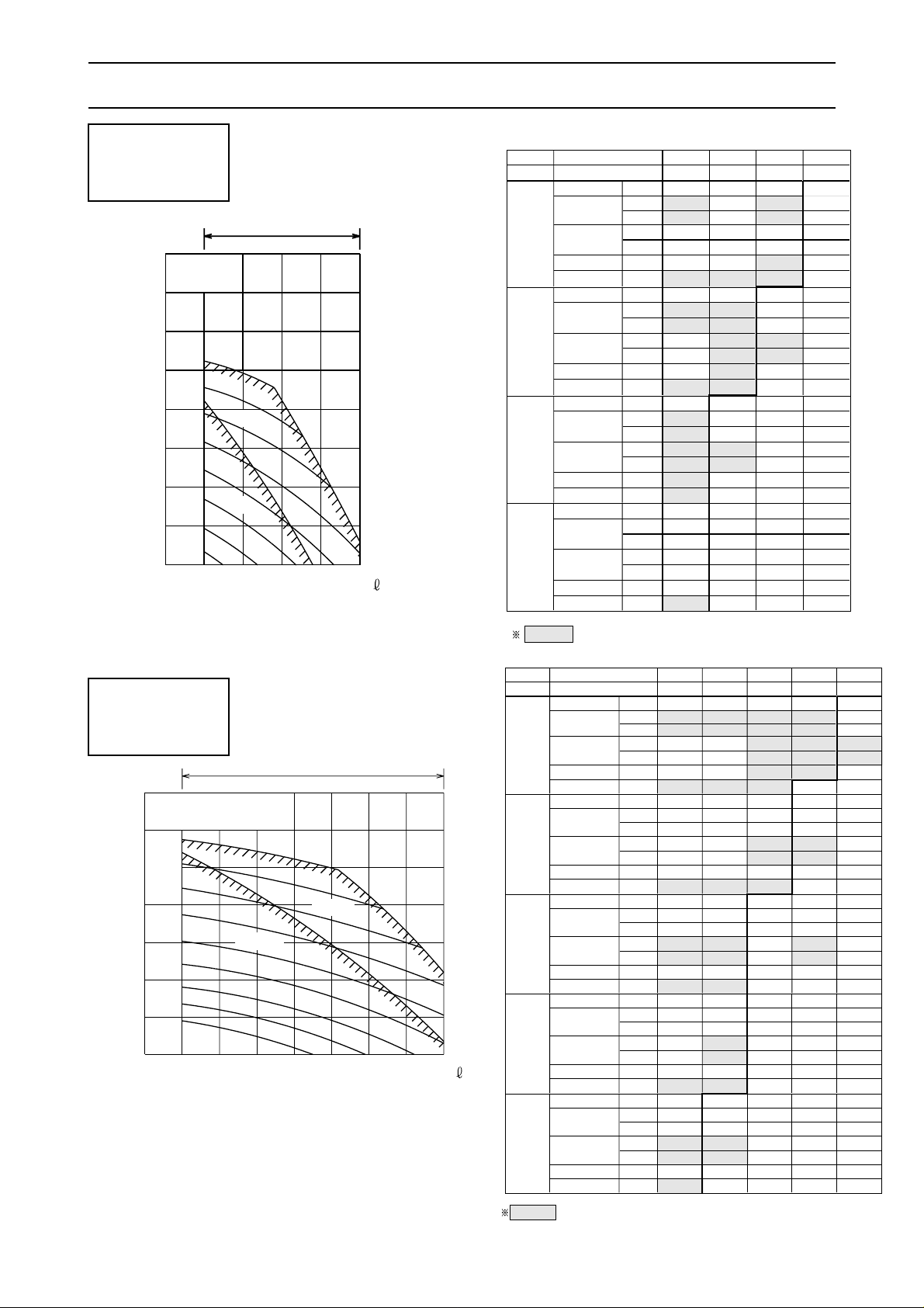
External static pressure (Pa)
(CMM)
Airflow
11701000 15001330
1800
1700
1600
1500
600
500
100
200
300
400
1100
1300
Operation range
Fan speed (rpm)
80 90
1000
1200
1400
60 70
1.5kW
1.1kW
( / s)
- 21 -
FAN PERFORMANCE
Airflow
750
( / s)
(CMM)
45
830
50
1000
60
Fan speed
(rpm)
1800
1700
1600
1500
1400
1300
1200
1100
100
200
300
400
500
External static pressure (Pa)
600
700
Operation range
0.75kW
1.1kW
External
static
pressure
(Pa)
CMM
45 50 55 60
L/S
750 830 920 1000
100
FAN SPEED rpm
1230 1320 1450 1450
PULLEY SIZE mm
139.7 127 139.7 139.7
(MOTOR SIDE) inch
5.5 5 5.5 5.5
PULLEY SIZE mm
165.1 139.7 139.7 139.7
(FAN SIDE) inch
6.5 5.5 5.5 5.5
BELT SIZE inch
B39 B36 B37 B39
MOTOR kw
0.75 0.75 0.75 1.1
200
FAN SPEED rpm
1330 1450 1580 1600
PULLEY SIZE mm
139.7 139.7 152.4 139.7
(MOTOR SIDE) inch
5.5 5.5 6 5.5
PULLEY SIZE mm
152.4 139.7 139.7 127
(FAN SIDE) inch
6 5.5 5.5 5
BELT SIZE inch
B38 B37 B40 B39
MOTOR kw
0.75 0.75 1.1 1.1
300
FAN SPEED rpm
1450 1580 1610 -
PULLEY SIZE mm
139.7 152.4 127 -
(MOTOR SIDE) inch
5.5 6 5 -
PULLEY SIZE mm
139.7 139.7 114.3 -
(FAN SIDE) inch
5.5 5.5 4.5 -
BELT SIZE inch
B37 B40 B37 -
MOTOR kw
0.75 1.1 1.1 -
400
FAN SPEED rpm
1610 - - -
PULLEY SIZE mm
127 - - -
(MOTOR SIDE) inch
5.0 - - -
PULLEY SIZE mm
114.3 - - -
(FAN SIDE) inch
4.5 - - -
BELT SIZE inch
B35 - - -
MOTOR kw
0.75 - - -
Std.
Airflow
CMM
60 70 80 90 95
L/S
1000 1170 1330 1500 1580
100
FAN SPEED rpm
1000 1090 1310 1310 1450
PULLEY SIZE mm
114.3 114.3 114.3 114.3 127
(MOTOR SIDE) inch
4.5 4.5 4.5 4.5 5.0
PULLEY SIZE mm
165.1 152.4 127 127 127
(FAN SIDE) inch
6.5 6.0 5.0 5.0 5.0
BELT SIZE inch
B39 B39 B37 B37 B35
MOTOR kw
1.1 1.1 1.1 1.5 1.5
200
FAN SPEED rpm
1230 1320 1450 1450 1580
PULLEY SIZE mm
139.7 127 127 127 152.4
(MOTOR SIDE) inch
5.5 5.0 5.0 5.0 6.0
PULLEY SIZE mm
165.1 139.7 127 127 139.7
(FAN SIDE) inch
6.5 5.5 5.0 5.0 5.5
BELT SIZE inch
B41 B39 B38 B35 B37
MOTOR kw
1.1 1.1 1.1 1.5 1.5
300
FAN SPEED rpm
1450 1450 1580 1600 -
PULLEY SIZE mm
127 127 152.4 139.7 -
(MOTOR SIDE) inch
5.0 5.0 6 5.5 -
PULLEY SIZE mm
127 127 139.7 127 -
(FAN SIDE) inch
5.0 5.0 5.5 5.0 -
BELT SIZE inch
B38 B38 B37 B35 -
MOTOR kw
1.1 1.1 1.5 1.5 -
400
FAN SPEED rpm
1580 1600 1690 - -
PULLEY SIZE mm
152.4 139.7 177.8
--
(MOTOR SIDE) inch
6.0 5.5 7.0 - -
PULLEY SIZE mm
139.7 127 152.4 - -
(FAN SIDE) inch
5.5 5.0 6.0 - -
BELT SIZE inch
B40 B39 B39
--
MOTOR kw
1.1 1.1 1.5 - -
500
FAN SPEED rpm
1740 1740 - - -
PULLEY SIZE mm
152.4 152.4
---
(MOTOR SIDE) inch
6.0 6.0 - - -
PULLEY SIZE mm
127 127 - - -
(FAN SIDE) inch
5.0 5.0 - - -
BELT SIZE inch
B39 B36
---
MOTOR kw
1.1 1.5 - - -
Airflow
External
static
pressure
(Pa)
Std.
PR-8YC
PRH-8YA
PRH-8YA-L
PR-5YC
PRH-5YA
PRH-5YA-L
Page 23
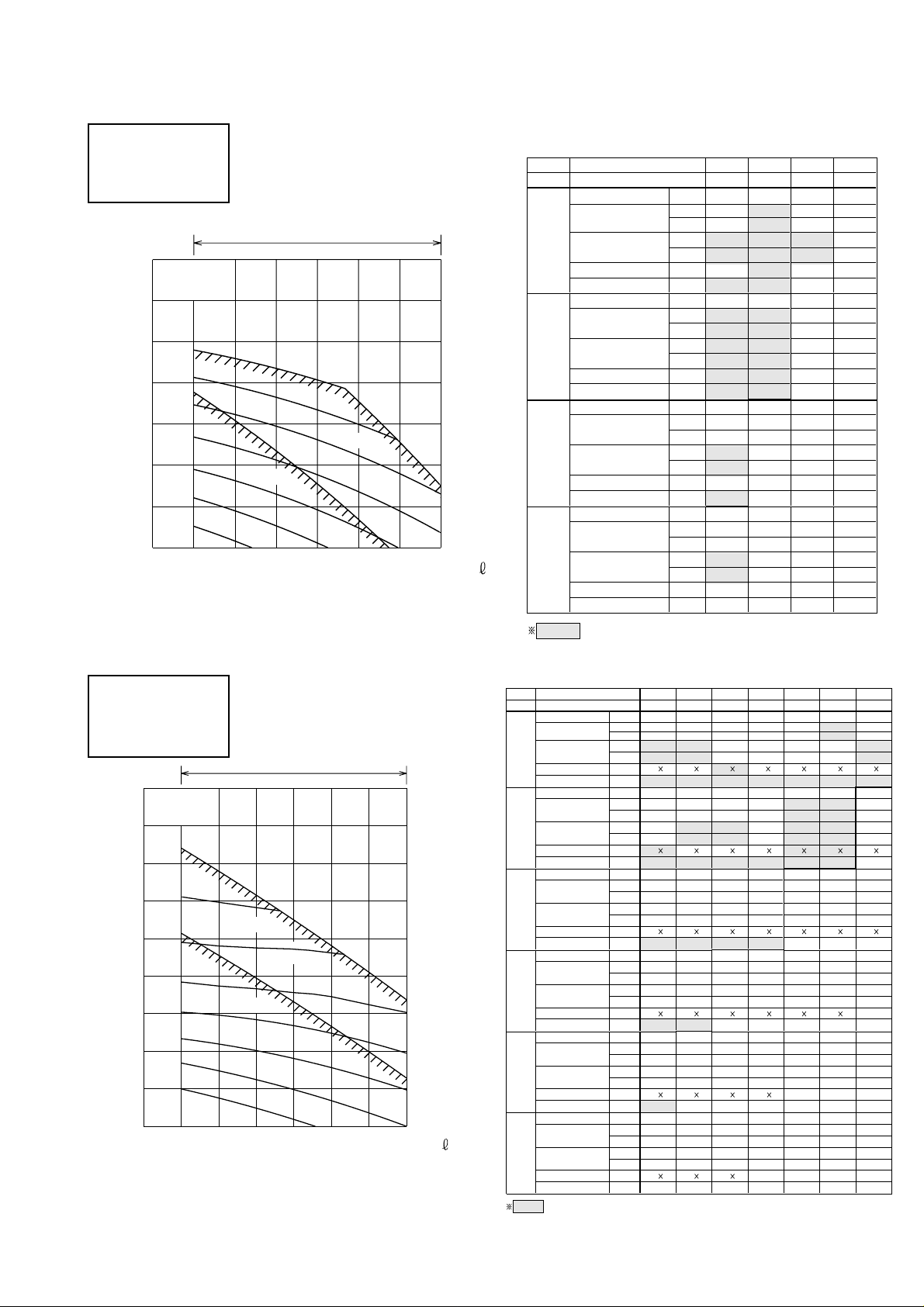
- 22 -
100
External static pressure (Pa)
(CMM)
( / s)
Airflow
183016701500 2000
200
1800
1700
1600
1500
120
600
400
300
500
Fan speed
(rpm)
1200
1400
90 100
1300
110
Operation range
2.2kW
1.5kW
CMM
90 100 110 120
L/S
1500 1660 1830 2000
100
FAN SPEED rpm
1320 1450 1450 1550
PULLEY SIZE mm
127 139.7 139.7 190.5
(MOTOR SIDE)
inch
5.0 5.5 5.5 7.5
PULLEY SIZE mm
139.7 139.7 139.7 177.8
(FAN SIDE) inch
5.5 5.5 5.5 7.0
BELT SIZE inch
B35 B36 B33 B39
MOTOR kw
1.5 1.5 2.2 2.2
200
FAN SPEED rpm
1450 1450 1600 -
PULLEY SIZE mm
139.7 139.7 139.7 -
(MOTOR SIDE) inch
5.5 5.5 5.5 -
PULLEY SIZE mm
139.7 139.7 127 -
(FAN SIDE) inch
5.5 5.5 5.0 -
BELT SIZE inch
B36 B36 B33 -
MOTOR kw
1.5 1.5 2.2 -
300
FAN SPEED rpm
1580 1600 1740 -
PULLEY SIZE mm
152.4 139.7 152.4 -
(MOTOR SIDE) inch
65.56.0-
PULLEY SIZE mm
139.7 127 127 -
(FAN SIDE) inch
5.5 5.0 5.0 -
BELT SIZE inch
B37 B33 B34 -
MOTOR kw
1.5 2.2 2.2 -
400
FAN SPEED rpm
1710 1740 - -
PULLEY SIZE mm
165.1 152.4 - -
(MOTOR SIDE) inch
6.5 6.0 - -
PULLEY SIZE mm
139.7 127 - -
(FAN SIDE) inch
5.5 5.0 - -
BELT SIZE inch
B35 B34 - -
MOTOR kw
2.2 2.2 - -
Airflow
External
static
pressure
(Pa)
Std.
800
100
External static pressure (Pa)
(CMM)
Airflow
2330 2670 30002000
Operation range
1200
1100
1000
900
800
700
600
120
700
500
300
600
400
200
180160140
Fan speed
(rpm)
2.2kW
3.0kW
( / s)
CMM
120 130 140 150 160 170 180
L/S
2000 2170 2330 2500 2670 2830 3000
100
FAN SPEED rpm
640 640 690 730 730 760 810
PULLEY SIZE mm
101.6 101.6 114.3 127 127 127 127
(MOTOR SIDE)
inch
4.0 4.0 4.5 5.0 5.0 5.0 5.0
PULLEY SIZE mm
228.6 228.6 241.3 254 254 241.3 228.6
(FAN SIDE) inch
9.0 9.0 9.5 10.0 10.0 9.5 9.0
BELT SIZE inch
B37 2 B37 2 B39 2 B41 2 B41 2 B40 2 B39 2
MOTOR kw
2.2 2.2 2.2 2.2 2.2 2.2 2.2
200
FAN SPEED rpm
760 810 810 850 890 890 910
PULLEY SIZE mm
127 127 127 127 139.7 139.7 127
(MOTOR SIDE) inch
5.0 5.0 5.0 5.0 5.5 5.5 5.0
PULLEY SIZE mm
241.3 228.6 228.6 215.9 228.6 228.6 203.2
(FAN SIDE) inch
9.5 9.0 9.0 8.5 9.0 9.0 8.0
BELT SIZE inch
B40 2 B39 2 B39 2 B38 2 B39 2 B39 2 B37 2
MOTOR kw
2.2 2.2 2.2 2.2 2.2 2.2 3.0
300
FAN SPEED rpm
910 910 910 970 1000 970 1040
PULLEY SIZE mm
127 127 127 127 139.7 127 127
(MOTOR SIDE) inch
5.0 5.0 5.0 5.0 5.5 5.0 5.0
PULLEY SIZE mm
203.2 203.2 203.2 190.5 203.2 190.5 177.8
(FAN SIDE) inch
8.0 8.0 8.0 7.5 8.0 7.5 7.0
BELT SIZE inch
B37 B37 B37 B36 B37 B36 B35
MOTOR kw
2.2 2.2 2.2 2.2 3.0 3.0 3.0
400
FAN SPEED rpm
1040 1040 1040 1040 1040 1040 -
PULLEY SIZE mm
127 127 127 127 127 127 -
(MOTOR SIDE) inch
5.0 5.0 5.0 5.0 5.0 5.0 -
PULLEY SIZE mm
177.8 177.8 177.8 177.8 177.8 177.8 -
(FAN SIDE) inch
7.0 7.0 7.0 7.0 7.0 7.0 -
BELT SIZE inch
B35 B35 B35 B35 B35 B35 -
MOTOR kw
2.2 2.2 3.0 3.0 3.0 3.0 -
500
FAN SPEED rpm
1120 1140 1120 1120 - - -
PULLEY SIZE mm
127 139.7 127 127 - - -
(MOTOR SIDE) inch
5.0 5.5 5.0 5.0 - - -
PULLEY SIZE mm
165.1 177.8 165.1 165.1 - - -
(FAN SIDE) inch
6.5 7.0 6.5 6.5 - - -
BELT SIZE inch
B34 B36 B34 B34 - - -
MOTOR kw
2.2 3.0 3.0 3.0 - - -
600
FAN SPEED rpm
1210 1230 1230 ----
PULLEY SIZE mm
127 139.7 139.7 ----
(MOTOR SIDE) inch
5.05.55.5----
PULLEY SIZE mm
152.4 165.1 165.1 ----
(FAN SIDE) inch
6.06.56.5----
BELT SIZE inch
B33B35B35 ----
MOTOR kw
333----
Airflow
External
static
pressure
(Pa)
Std.
2 2 2 2 2 2
2
2
2 2 2 2 2
2 2 2 2
2 2 2
PR-10YC
PRH-10YA
PRH-10YA-L
PR-15YC
PRH-15YA
PRH-15YA-L
Page 24
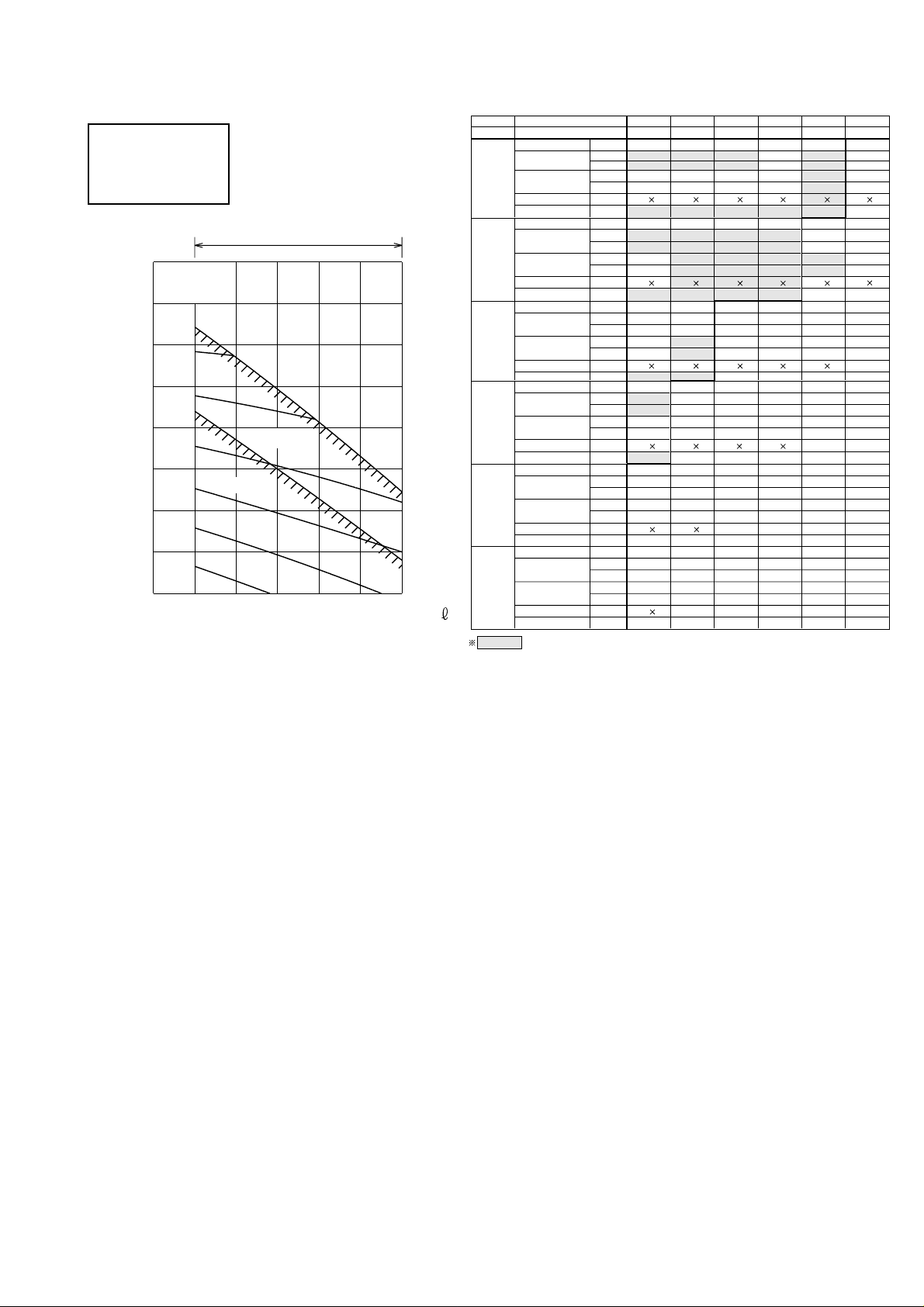
- 23 -
100
200
External static pressure (Pa)
(CMM)
Airflow
2830 367033303000
Operation range
400
600
300
500
700
1200
1100
1000
900
800
700
180
200 220170
Fan speed
(rpm)
4.0kW
3.0kW
( / s)
CMM 170 180 190 200 210 220
L/S 2830 3000 3170 3330 3500 3670
100
FAN SPEED rpm
730 810 810 840 910 940
PULLEY SIZE
mm
127 127 127 139.7 127 139.7
(MOTOR SIDE) inch
5.0 5.0 5.0 5.5 5.0 5.5
PULLEY SIZE mm 254 228.6 228.6 241.3 203.2 215.9
(FAN SIDE) inch 10.0 9.0 9.0 9.5 8.0 8.5
BELT SIZE inch B43 B41 B41 B42 B39 B41
MOTOR kw 3.0 3.0 3.0 3.0 3.0 4.0
200
FAN SPEED rpm
850 910 910 910 1000 970
PULLEY SIZE mm 127 127 127 127 139.7 127
(MOTOR SIDE) inch 5.0 5.0 5.0 5.0 5.5 5.0
PULLEY SIZE mm 215.9 203.2 203.2 203.2 203.2 190.5
(FAN SIDE) inch 8.5 8.0 8.0 8.0 8.0 7.5
BELT SIZE inch B40 B39 B39 B39 B40 B38
MOTOR kw 3.0 3.0 3.0 3.0 4.0 4.0
300
FAN SPEED rpm
940 1000 1040 1040 1040 -
PULLEY SIZE mm 139.7 139.7 127 127 127 -
(MOTOR SIDE) inch 5.5 5.5 5.0 5.0 5.0 -
PULLEY SIZE mm 215.9 203.2 177.8 177.8 177.8 -
(FAN SIDE) inch 8.5 8.0 7.0 7.0 7.0 -
BELT SIZE inch B41 B40 B37 B37 B37 -
MOTOR kw
3.0 3.0 4.0 4.0 4.0
-
400
FAN SPEED rpm
1040 1040 1060 1120 - -
PULLEY SIZE mm 127 127 139.7 127 - -
(MOTOR SIDE) inch 5.0 5.0 5.5 5.0 - -
PULLEY SIZE mm 177.8 177.8 190.5 165.1 - -
(FAN SIDE) inch 7.0 7 7.5 6.5 - -
BELT SIZE inch B37 B37 B39 B36 - -
MOTOR kw 3.0 4.0 4.0 4.0 - -
500
FAN SPEED rpm
1140 1120 ----
PULLEY SIZE mm 139.7 127 ----
(MOTOR SIDE) inch 5.55.0----
PULLEY SIZE mm 177.8 165.1 ----
(FAN SIDE) inch 7.06.5----
BELT SIZE inch B38 2B36 2----
MOTOR kw 44----
600
FAN SPEED rpm
1230 -----
PULLEY SIZE mm 139.7 -----
(MOTOR SIDE) inch 5.5-----
PULLEY SIZE mm 165.1 -----
(FAN SIDE) inch 6.5-----
BELT SIZE inch B37-----
MOTOR kw 4.0-----
2 2 2 2
2 2 2 2 2
2 2 2 2 2
2 2 2
2
2 2 2
2
Airflow
External
static
pressure
(Pa)
Std.
PR-20YC
PRH-20YA
PRH-20YA-L
Page 25
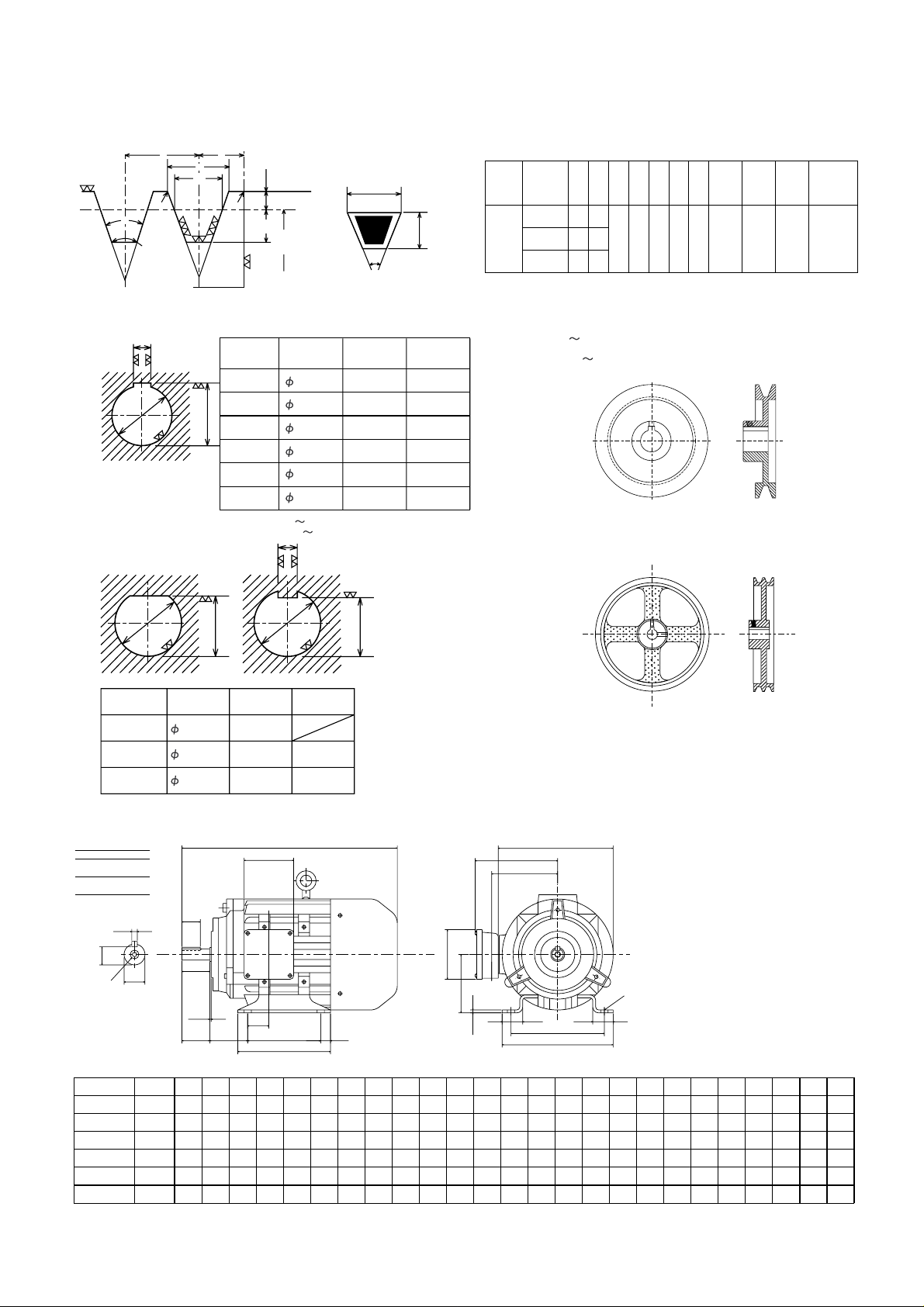
- 24 -
e
a
r1 r3
f
w
L0
r2 r2
K
K0
øP.C
16.5mm
B type
11.0mm
40˚
Sectional plan of V-belt
Shape of
V-belt
Nominal
Dia. øP.Ca( ˚
)
L0W K K0 e f r1 r2 r3
V-belt
thickness
(Reference)
B
Over 125
Under 160
Over 160
Under 200
Over 200
34
15.86
36
38
16.07
16.29
12.5 5.5 9.5 19.0 12.5 0.2~0.5 0.5~1.0 1~2 11
Pulley outside dimensions are shown below: (Unit : mm)
(1) Shape of belt groove
(2) Shape of motor pulley boss (Unit : mm)
PR-5 10
PRH-5 10 Pulley for blower & motor
b
c
a
b
a
cba
20
20
25
-0.020
-0.007
19
16.5
21.0
0
- 0.1
0
- 0.1
0
- 0.1
6
8
0
- 0.036
MODEL
PR-5
PRH-5
PR-8,10
PRH-8, 10
PR-15,20
PRH-15, 20
-0.020
-0.007
-0.020
-0.007
0
- 0.036
PR-5
PRH-5
CBA
MOTOR
CAPACITY
(kW)
0.75
1.1
1.5
2.2, 3.0
4.0
5.5
19
24
24
28
28
38
+0.009
- 0.004
+0.009
- 0.004
+0.009
- 0.004
+0.009
- 0.004
+0.009
- 0.004
+0.018
- 0.002
15.5
20.0
20.0
23.9
23.9
33.0
0
- 0.2
0
- 0.2
0
- 0.2
0
- 0.2
0
- 0.2
0
- 0.2
6
8
8
8
8
10
+0.073
+0.040
+0.073
+0.040
+0.073
+0.040
+0.073
+0.040
+0.073
+0.040
+0.089
+0.050
B
C
A
PR-8 20
PRH-8 20
PR-15,20
PRH-15, 20 Pulley for blower & motor
ED
L
E
EB
E C B CRS
BB
BC
LL
øD
F
Shaft
tapped
DH x EH
deep
AC
TBH
H
+0
-0.5
AB
A CRS
AAAA
HA
TBW
AE
AD
G
+0
-0.2
SHAFT
Diameter
19 to 28
Limits
+0.009
-0.004
+0.018
-0.002
32 to 48
Holes
K Dia.
OUT PUT
0.75
1.1
1.5
2.2,3.0
4.0
5.5 132S
112M
100L
90N
90SN
80
Size
Frame
125
140
140
160
190
216
AB
100
100
125
140
140
140
C
50
56
56
63
70
89
H
80
90
90
100
112
132
K
10
10
10
12
12
12
D
19
24
24
28
28
38
E
40
50
50
60
60
80
F
6
8
8
8
8
10
G
15.5
20
20
23.9
23.9
33
ED
25
32
32
40
40
56
DH
M6
M8
M8
M10
M10
M12
EH
16
19
19
22
22
28
AA
27
28
28
28
35
38
AB
157
174
174
184
218
243
BB
127
152
152
170
170
208
BC
13.5
38.5
13.5
15
15
53
L
295
320
320
371
377
458
HA
4
4
4
4
4
5
AC
158
178
178
208
215
257
AD
132
140
140
138
164
189
AE
102
110
110
120
130
154
EB
1.5
1.5
1.5
1.6
1.6
1.6
LL
75
100
100
23
23
26
TBW
103
103
103
103
131
131
TBH
103
103
103
103
131
131
Shaft GeneralFixing
(3) Shape of motor (Unit : mm)
Page 26

- 25 -
NC CURVES
NC-20
NC-30
NC-40
NC-50
NC-60
NC-70
50Hz
Note. The measuring point is 1m from the comp. service panel.
20
30
40
50
60
70
80
90
45
octave-band frequency [Hz]
octave-band lebel db (0db=0.0002ubar)
over
all
63 90 125 180 250 355 500 710
1000 1400 2000 2800 4000 5600 8000
10
7064db
COOLING &
HEATING
50525658606267
500 Hz250 Hz125 Hz
8000 Hz4000 Hz2000 Hz1000 Hz
63 HzCONDITION A scale
NC-70
NC-60
NC-50
NC-40
NC-30
NC-20
50Hz
Note. The measuring point is 1m from the comp. service panel.
20
30
40
50
60
70
80
90
45
octave-band frequency [Hz]
octave-band lebel db (0db=0.0002ubar)
over
all
63 90 125 180 250 355 500 710
1000 1400 2000 2800 4000 5600 8000
10
COOLING &
HEATING
6762db 43455057616263
500 Hz250 Hz125 Hz 8000 Hz4000 Hz2000 Hz1000 Hz63 HzCONDITION A scale
PR-5YC
PRH-5YA
PRH-5YA-L
PR-8YC
PRH-8YA
PRH-8YA-L
Page 27

NC-20
NC-30
NC-40
NC-50
NC-60
NC-70
50Hz
Note. The measuring point is 1m from the comp. service panel.
COOLING &
HEATING
71 4449575961636964db
500 Hz250 Hz125 Hz
8000 Hz4000 Hz2000 Hz1000 Hz
63 HzCONDITION A scale
20
30
40
50
60
70
80
90
45
octave-band frequency [Hz]
octave-band lebel db (0db=0.0002ubar)
over
all
63 90 125 180 250 355 500 710
1000 1400 2000 2800 4000 5600 8000
10
68db
COOLING &
HEATING
NC-20
NC-30
NC-40
NC-50
NC-60
NC-70
50Hz
76
Note. The measuring point is 1m from the comp. service panel.
48515962656876
500 Hz250 Hz125 Hz 8000 Hz4000 Hz2000 Hz1000 Hz63 Hz
CONDITION
A scale
20
30
40
50
60
70
80
90
45
octave-band frequency [Hz]
octave-band lebel db (0db=0.0002ubar)
over
all
63 90 125 180 250 355 500 710
1000 1400 2000 2800 4000 5600 8000
10
- 26 -
PR-10YC
PRH-10YA
PRH-10YA-L
PR-15YC
PRH-15YA
PRH-15YA-L
Page 28

68db
COOLING &
HEATING
NC-20
NC-30
NC-40
NC-50
NC-60
NC-70
50Hz
10
8000560040002800200014001000
7105003552501801259063
all
over
octave-band lebel db (0db=0.0002ubar)
octave-band frequency [Hz]
45
90
80
70
60
50
40
30
20
A scale
CONDITION
63 Hz 1000 Hz 2000 Hz 4000 Hz 8000 Hz125 Hz 250 Hz 500 Hz
77 70 65 60 58 51 48
Note. The measuring point is 1m from the comp. service panel.
73.5
OUTLINE DIMENSIONS
- 27 -
25103025
25
WIRING HOLE
1534
80
80
25
26.5
424
25(1030)
25
15
742 742
22
22
42
30019941049
1000
49
1600
944
470
607
16-ø3.5 HOLES
16-ø3.5 HOLES
30
21021021021030
900
10
25
200200
20020025
A
65
10
65
10
410
25 180 180 25
65
300
20 130 130
20
65
10
850
54.5 971 54.5
1080
50
40 1000 40
900 50
75
850 75
4- ø25
SASPENSION HOLES
DRAIN 1B PT
A(DETAIL)
CONDENSER AIR OUTLET
SUPPLY AIR
RETURN AIR
6-15X25 MTG HOLES
CONDENSER AIR INLET
(2 SIDES)
CONTROL BOX
RETURN AIR DUCT FLANGE
SUPPLY AIR DUCT FLANGE
PR-5YC
PRH-5YA
PRH-5YA-L
PR-20YC
PRH-20YA
PRH-20YA-L
Page 29

- 28 -
55.5
85
1820
85
55.5
35
35
1990
1742.7
25
25 37
556.5
49
464
24
235
717
10
2010
10
464 428
1879
62
990
540
428
1200
54.5
22
54.5
2060
1951
22
1080
1840
25
25
2010
1879
1820
60
60
150150 200 200 200 200200200200
200 200
32
14 200 200 14
10
62
62
32
62
WIRING HOLE
DRAIN 1B PT
CONDENSER
AIR INLET
(3 SIDES)
SUPPLY AIR
RETURN AIRRETURN AIR
A (DETAIL)
A
6-15X25 MTG HOLES
26-ø3.5 HOLES
26-ø3.5 HOLES
CONTROL BOX
RETURN AIR DUCT FLANGE
SUPPLY AIR DUCT FLANGE
CONDENSER AIR OUTLET
39.5
200 200 200 200200200200200 200
39.5
25
15
37
101 131
4-ø25
26.5
25
827
43
862
SUSPENSION HOLES
10
PR-15,20YC
PRH-15, 20YA
PRH-15, 20YA-L
424
1534
80
25133025
25
80
40 40
75
25 742 742
26.5
49
607
15
25
(1330)
25
50 1200 50
65
10
1200
30
30
190 190 190 190 190 190
65
10
410
25 180 180 25
65
10
300
20 130 130 20
65
10
1150
35 180 180 180 180 180 180 35
1600
470
944
1000
49 410 199 300 42
75
1300
1150
1380
127154.5
54.5
22
22
CONTROL BOX
4-ø25
SASPENSION HOLES
WIRING HOLE
DRAIN 1B PT
CONDENSER AIR INLET
(2 SIDES)
20-ø3.5 HOLES
20-ø3.5 HOLES
6-15X25 MTG HOLES
A(DETAIL)
A
RETURN AIR DUCT FLANGE
SUPPLY AIR DUCT FLANGE
RETURN AIR
SUPPLY AIR
CONDENSER AIR
OUTLET
PR-8,10YC
PRH-8, 10YA
PRH-8, 10YA-L
Page 30

- 29 -
WIRING DIAGRAMS
FZ0
FZ1
30
CZ
FZ0
30
CZ
30
CZ
FZ1
CZ
52C
(3MIN)
TM
52C
FZ1
CH
PR-10YC ···60A
MF2
INTERNAL
PROTECTOR
11
PR- 8YC ···50A
7
51F1
CIRCUIT BREAKER
(FIELD SUPPLY)
MC
INTERNAL
PROTECTOR
C
51
1
51C
3
2
1
51F2
3
26L
23
WA
CZ
WHITE
TB2
BLACK
RED
51F1
MF1
WHITE
RED
52F
TB2
T1
T2
S1
S2
R1
R2
RED
RED
RED
WHITE
WHITE
BLACK
BLACK
BLACK
BLACK
F
52C
WHITE
(3.15A)
BLACK
WHITE
RED
BLACK
RED
BLUE
WHITE
RED
TB1
L1
L2
L3
N
PE
F
Power Supply
50Herts
380~415Volt
3Phase
<SW2>
51C
MF2
<23WA>
30CZ
51F1, 2
Name
Symbol
TM
Tr
TB1~4
<SW1>
FZ0·1
CZ
<RL>
<GL>
F
26L
CH
MC
MF1
52C
63H
52F
52F
12
TB3
11
TB3
52C
CZ
TM
(3.15A)
F
5
RL
51F2
AC
220~
240V
AC
24V
Tr
3
TB4
TB4
SWITCH BOX
(FIELD SUPPLY)
1
SW1
SW2
246
GL
63H
TB3
12
Note:
1.The dotted lines show field wiring.
2.The figure in the parentheses show field supply parts.
3.Color of earth wire is yellow and green twisting.
4.Not specified color of wire is brown.
5.Specification subject to change without notice.
Caution,
1.To protect each Fan motors and Compressors from abnormal current,
these Over current relays<51C>,<51F1,2>are installed.
Therefore,do not change factory set value of these Over current relays.
2.To protect the compressor from frequently "ON-OFF" ,timer<TM>is
installed. Therefore,do not change factory set value of this timer.
PR- 5YC ···40A
Thermostat(freeze protection)
Fan motor (in door)
Fuse
Transformer
Crankcase heater
Contactor (fan I/D)
Over current relay (fan I/D,O/D)
Contactor (compressor)
Fan motor (out door)
Over current relay(compressor)
High-pressure switch
Terminal block
Thermostat (room temp.)
Timer (anti short cycle)
Lamp (operation)
Lamp (check)
Switch (off)
Switch (on)
Auxiliary relay (check)
Auxiliary relay (compressor)
Auxiliary relay (fan)
Compressor motor
15
8,20YC ONLY
PR-5, 8, 10YC (STANDARD)
Page 31

- 30 -
FZ0
2
GL
MF1
52
C2
52
C1
52
F
TM
CZ1
CZ2
FZ1
CZ2
FZ1
63
H2
51F3
3
1
51C2
26
L2
CZ2-2
CZ1-2
30
FZ0
50Hertz
380~415Volt
3Phase
Power supply
CH2
CH1
PR -15YC···100A
PR -20YC···125A
TM
(3MIN)
CZ2-1
30
FZ0
CZ1-1
30
L3
PE
L2
L1
CIRCUIT BREAKER
(FIELD SUPPLY)
CZ2
L1
C1
26
51
1
3
51F2
H1
63
9
CZ2
30
CZ1
30
FZ1
51F3
51F2
52
52
C1
C2
RL2
RL1
Low
High
CZ2-1
CZ1-1
AC
24V
AC
220~
240V
Tr
23 45
6
8
7
1
23WA
SWITCH BOX
(FIELD SUPPLY)
F
TB4 12
TB412
(2SEC)
C2C1
TB4 11
TB5
TB5
CZ1
CZ1
SW
2
SW1
52
52
2
30
30
1
2
3
51F1
F(3.15A)
F
(3.15A)
52F
51F1
51C1
51C2
52C1
52C2
N
TB1
TB2
TB3
21 22
21 22
21 22
T
TT
S
SS
R
RR
Blue
Black
Black
Black
Black
Black
Black
Black
Black
Black
Black
Black
White
White
White
White
White
White
White
White
White
White
Red
Red Red
Red
Red
Red
Red
Red
Red
Red
Red
Red
Red
Note:
1.The dotted lines show field wiring.
2.The figure in the parentheses show field supply parts.
3.Color of earth wire is yellow and green twisting.
4.Not specified color of wire is brown.
5.Specification subject to change without notice.
Caution,
1.To protect each Fan motors and Compressors from abnormal current,
these Over current relays <51C1,2> , <51F1,2,3> are installed.
Therefore,do not change factory set value of these Over current relays.
2.To protect the compressors from frequently "ON-OFF" ,timer <TM> is
installed. Therefore,do not change factory set value of this timer.
3.This timer <2> installed so that two compressors may never start at
the same time. The unit stop if the set value of the timer is changed.
INTERNAL
PROTECTOR
MF2
MF3
INTERNAL
PROTECTOR
MC1
INTERNAL
PROTECTOR
INTERNAL
PROTECTOR
MC2
C1
52
1
2
3
11
12
11
12
12
T
S
R
11
TB4 14
Black
CZ1-2
30
CZ2-2
30
30
TM
(3MIN)
C2
52
Thermostat(freeze protection)
26L1·2
Name
F
51C1·2
Tr
CH1·2
52F
51F1~3
52C1·2
MF2·3
MF1
MC1·2
63H1·2
TB1~5
Fan motor (in door)
Fuse
Transformer
Crankcase heater
Contactor (fan I/D)
Over current relay (fan I/D,O/D)
Contactor (compressor)
Fan motor (out door)
Over current relay(compressor)
High-pressure switch
Terminal block
Thermostat (room temp.)
Timer (anti short cycle)
Timer
Lamp (power on)
Lamp (check)
<23WA>
<RL1·2>
<GL>
TM
2
FZ0·1
<SW1>
<SW2>
30CZ1-1,2
CZ1·2
Switch (off)
Switch (on)
Auxiliary relay (check)
Auxiliary relay (compressor)
Auxiliary relay (fan)
Symbol
Compressor motor
30CZ2-1,2
Auxiliary relay (check)
PR-15, 20YC (STANDARD)
Page 32
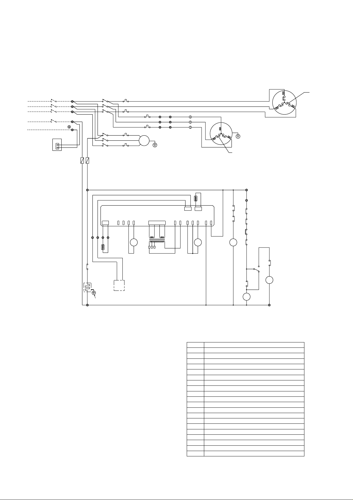
- 31 -
PR- 8YC ···50A
30
CZ
30
CZ
52C
30
CZ
MF1
52F
FZCZ
Over current relay(compressor)
High-pressure switch
Terminal block
Fuse
Transformer
Crankcase heater
Contactor(fan I/D)
Over current relay(fanI/D,O/D)
Contactor(compressor)
Fan motor(outdoor)
Fan motor(indoor)
Compressor motor
63H
TB1~4
51C
Surge absorber circuit boardDSA
R/C
TH5 Thermistor(room temp.)
Remote controller
Thermistor(pipe)
Indoor board
FZ
Auxiliary relay(check)
Auxiliary relay(compressor)
Auxiliary relay(fan)
TH2
IB
30CZ
CZ
Tr
F
CH
52F
51F1,2
52C
MF2
MF1
MC
Name
Symbol
DCBA
TB4
Green/Yellow
Blue
CN
DSA
3
1
CZ
FZ
CH
PR- 5YC ···40A
15
3Phase
Power supply
TB1
L1
L2
L3
PE
380~415Volt
50Hertz
N
CIRCUIT BREAKER
(FIELD SUPPLY)
51C
51F1
63H
51F2
TH5
R/C
51F2
Red
White
Black
51C
Black
Red
Black
White
Red
3
2
1
TB3 12
TB3 12
TB3 11
T
S
R
2
T
2
S
2
R
FZ
TH2
Tr
IB
52C
F(3.15A)
52F
51F1
52C
TB2
1
1
1
Black
Black
White
Blue
RedRed
Black
White
Red
MF2
INTERNAL
PROTECTOR
INTERNAL
PROTECTOR
MC
Note:
1.The dotted lines show field wiring.
2.The figure in the parentheses show field supply parts.
3.Color of earth wire is yellow and green twisting.
4.Not specified color of wire is brown.
5.Specification subject to change without notice.
Caution,
To protect each Fan motors and Compressor from abnormal current,
these Over current relays<51C>,<51F1,2>are installed.
Therefore,do not change factory set value of these Over current relays.
PR-10YC ···60A
11
8,10YC ONLY
PR-5, 8, 10YC
(SPECIAL ORDER : K CONTROL)
Page 33
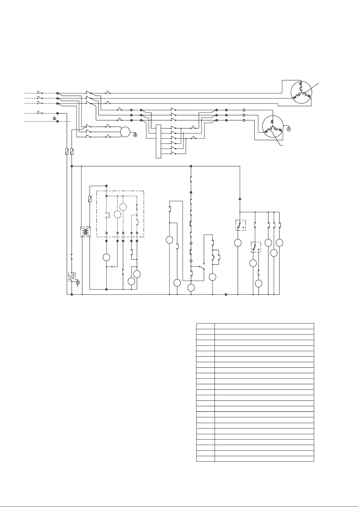
- 32 -
52C
30
CZ
30
CZ
C
FZ1
FZ0
FZ4
FZ3
52F252
F4
52
F3
FZ2
52
F1
GL
RL
TM
MF1
CZ
Timer (anti short cycle)TM
<GL>
<RL>
Lamp (operation)
Lamp (check)
Thermostat (room temp.)
<23WA>
Switch (on)
<SW1>
Switch (off)
30CZCZAuxiliary relay (check)
Auxiliary relay (compressor)
Auxiliary relay (fan)FZ0,1
Contactor (fan O/D)
Auxiliary relay (fan O/D)
FZ2~4
52F2~4
<SW2>
52F1
Thermostat(freeze protection)26L
High-pressure switch
63H
Name
F
51C
Tr1·2
CH
51F1,2,3
52C
MF2
MF1
MC
TB1~4
Fan motor (indoor)
Fuse
Transformer
Crankcase heater
Contactor (fan I/D)
Over current relay(fanI/D,O/D)
Contactor (compressor)
Fan motor (outdoor)
Over current relay(compressor)
Terminal block
Symbol
Compressor motor
15
11
12
51F3
14
FZ1
(3MIN)
TM
C
52
CZ
3
51
26L
1
51F2
63H
51F1
FZ1
FZ0
CZ
30
CH
PR -10YC ···60A
PR - 8YC ···50A
(3.15A)
F
Power supply
3Phase
TB1
CIRCUIT BREAKER
(FIELD SUPPLY)
N
PE
50Hertz
380~415Volt
L3
L2
L1
7
3
FZ
FZ
2
4
FZ
2
FZ
3
FZ
26D4
26D3
51F2
White
51F3
2
T
2
S
2
R
TB2
T
2
S
2
2
R
Black
Black
White
Red
Red
3
2
1
Black
Red
Tr1
52F4
52F3
TB2
R
S
T
1
1
1
52F2
Black
White
Red
T
S
R
1
1
1
CZ
AC
24V
AC
220~
240V
Tr2
6
5432
1
23WA
SWITCH BOX
(FIELD SUPPLY)
TB4
TB4
SW1
SW2
TB3 12
TB3 11
52C
F(3.15A)
52F1
51F1
51C
52C
Black
Black
Black
White
White
Blue
RedRed
Red
Black
White
Red
MF2
INTERNAL
PROTECTOR
INTERNAL
PROTECTOR
MC
Note:
1.The dotted lines show field wiring.
2.The figure in the parentheses show field supply parts.
3.Color of earth wire is yellow and green twisting.
4.Not specified color of wire is brown.
5.Specification subject to change without notice.
Caution,
1.To protect each Fan motors and Compressor from abnormal current,
these Over current relays<51C>,<51F1,2,3>are installed.
Therefore,do not change factory set value of these Over current relays.
2.To protect the compressor from frequently "ON-OFF" ,timer<TM>is
installed. Therefore,do not change factory set value of this timer.
PR - 5YC ···40A
8,10YC ONLY
PR-5, 8, 10YC
(SPECIAL ORDER : LOW TEMPERATURE)
Page 34
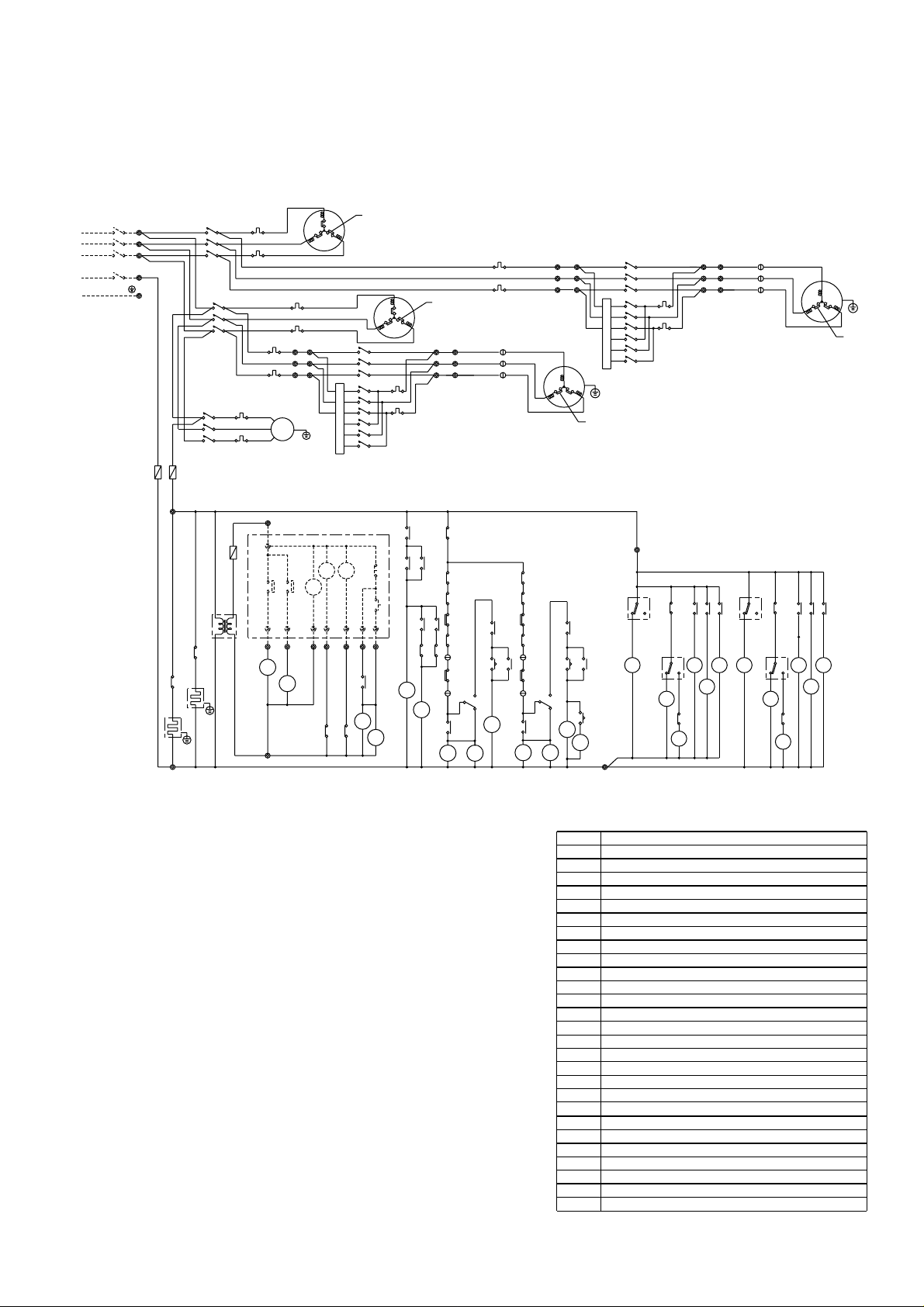
- 33 -
Note:
1.The dotted lines show field wiring.
2.The figure in the parentheses show field supply parts.
3.Color of earth wire is yellow and green twisting.
4.Not specified color of wire is brown.
5.Specification subject to change without notice.
Caution,
1.To protect each Fan motors and Compressors
from abnormal current,these Over current relays<51C1,2>,
<51F1~5>are installed.
Therefore,do not change factory set value of these Over current relays.
2.To protect the compressors from frequently "ON-OFF",timer<TM>is
installed. Therefore,do not change factory set value of this timer.
3.This timer<2>installed so that two compressors may never start at
the same time. The unit stop if the set value of the timer is changed.
C1
52
1
2
3
11 12
11 12
12
T
S
R
11
Black
T
S
R
Thermostat (room temp.)
Thermostat(freeze protection)
Timer (anti short cycle)
Timer
Lamp (operation)
Lamp (check)
26L1·2
<23WA>
<RL1·2>
<GL>
TM
2
Name
F
51C1·2
Tr1~3
CH1·2
52F1
51F1~5
52C1·2
MF2·3
MF1
MC1·2
FZ0·1
<SW1>
<SW2>
30CZ1-1, 2
CZ1·2
63H1·2
TB1~5
Fan motor (indoor)
Fuse
Transformer
Crankcase heater
Contactor (fan I/D)
Over current relay (fan I/D,O/D)
Contactor (compressor)
Fan motor (outdoor)
Over current relay(compressor)
Switch (off)
Switch (on)
Auxiliary relay (check)
Auxiliary relay (compressor)
Auxiliary relay (fan)
High-pressure switch
Terminal block
Symbol
Compressor motor
Thermostat (ambiemt temp.)
FZ0
2
GL
MF1
52
C2
52
C1
52
F
TM
CZ1
CZ2
FZ1
CZ2
FZ1
63
H2
51F3
3
1
51
26
C2
L2
CZ2-2CZ1-2
30
FZ0
50Hertz
380~415Volt
3Phase
Power supply
CH2
CH1
PR -15YC···100A
PR -20YC···125A
TM
(3MIN)
CZ2-1
30
FZ0
CZ1-1
30
L3
L2
L1
CIRCUIT BREAKER
(FIELD SUPPLY)
CZ2
L1
26
51C1
1
3
51F2
H1
63
10
CZ2
30
CZ1
30
FZ1
51F3
51F2
52
52
C1
C2
RL2
RL1
CZ2-1
CZ1-1
AC
24V
AC
220 ~
240V
Tr
23 5
4
6
8
7
1
SWITCH BOX
(FIELD SUPPLY)
F
TB4 12
11
(2SEC)
C2C1
TB4 11
TB5
TB5
CZ1
CZ1
SW
2
SW1
52
52
2
30
30
1
2
3
51F1
F(3.15A)
F
(3.15A)
52F
51F1
51C1
51C2
52C1
52C2
N
TB1
TB2
TB3
22
22
22
T
T
S
S
R
R
Blue
Black
Black
Black
Black
Black
Black
Black
Black
Black
White
White
White
White
White
White
White
White
Red
Red Red
Red
Red
Red
Red
Red
Red
Red
Red
INTERNAL
PROTECTOR
MF2
MF3
INTERNAL
PROTECTOR
MC1
INTERNAL
PROTECTOR
INTERNAL
PROTECTOR
MC2
30
TM
(3MIN)
C2
52
22
22
22
T
S
R
TB2
CZ1-2
30
CZ2-2
30
51F4 51F5
52
F3
52
F6
52
F4
52
F7
52
F2
52
F5
FZ4
FZ7
FZ3
FZ6
FZ2 FZ5
52F2~7
FZ2~7
26D1~4
Contactor (fan O/D)
Auxiliary relay (fan O/D)
TB4 12
36
25
47
25
3
6
FZ FZ
FZ FZ
FZ FZ
FZ FZ
FZ FZ
26D2
26D4
26D1
26D3
TB3
21
21
21
T
S
R
21
21
21
51F5
Red
White
Black
Tr2
52F7
52F5
Black
White
Red
52F6
11
11
11
T
S
R
51F4
Red
White
Black
Tr1
52F4
52F2
Black
White
Red
52F3
12
12
12
T
S
R
30CZ2-1, 2
Auxiliary relay (check)
TB4
Low
High
23WA
PE
PR-15, 20YC
(SPECIAL ORDER : LOW TEMPERATURE)
Page 35
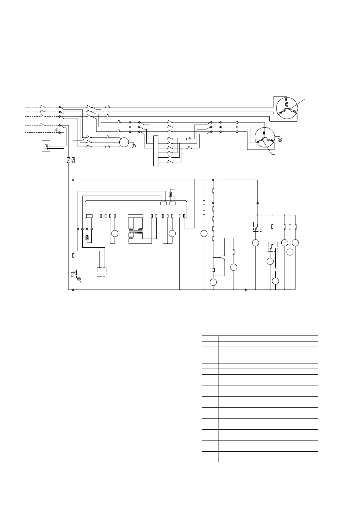
- 34 -
30
CZ
30
CZ
52C
30
CZ
FZ4
FZ3
52
F1
MF1
52F252
F4
52
F3
FZ2
FZ1
CZ
Surge absorber circuit board
DSA
Thermistor(room temp)
TH5
Remote controller
R/C
FZ2~4
Auxiliary relay(fan O/D)
52F2~4
Contactor(fan O/D)
Thermistor(pipe)
Indoor board
(compressor)
Over current relay
FZ1
Auxiliary relay(check)
Auxiliary relay(compressor)
Auxiliary relay(fan)
High-pressure switch
Terminal block
Fuse
Transformer
Crankcase heater
Contactor(fan I/D)
Over current relay(fanI/D,O/D)
Contactor(compressor)
Fan motor(outdoor)
Fan motor(indoor)
Compressor motor
TH2
IB
30CZ
CZ
63H
TB1~4
51C
Tr1·2
F
CH
52F1
51F1,2,3
52C
MF2
MF1
MC
Name
Symbol
15
11
12
14
51F3
TB4
DCBA
Green/Yellow
Blue
DSA
CN
3
1
PR -10YC ···60A
PR - 8YC ···50A
CIRCUIT BREAKER
(FIELD SUPPLY)
CZ
FZ1
CH
51F1
51F2
White
51F2
51F3
R/C
TH5
51C
63H
3
FZ
FZ
2
Tr1
52F4
52F3
R
S
T
TB2
1
1
1
2
T
2
S
2
R
TB2
T
2
S
2
2
R
52F2
Black
Black
Black
White
White
Red
Red
Red
3
2
1
TB3 12
TB3 11
T
S
R
4
FZ
2
FZ
3
FZ
26D4
26D3
FZ1
TH2
Tr2
IB
52C
F(3.15A)
52F1
51F1
51C
52C
N
PE
50Hertz
380~415Volt
3Phase
Power supply
L3
L2
L1
TB1
1
1
1
Black
Black
Black
Black
White
White
Black
Red
Red
RedRed
Blue
White
Red
MF2
INTERNAL
PROTECTOR
MC
INTERNAL
PROTECTOR
Note:
1.The dotted lines show field wiring.
2.The figure in the parentheses show field supply parts.
3.Color of earth wire is yellow and green twisting.
4.Not specified color of wire is brown.
5.Specification subject to change without notice.
Caution,
To protect each Fan motors and Compressor from abnormal current,
these Over current relays<51C>,<51F1,2,3>are installed.
Therefore,do not change factory set value of these Over current relays.
PR - 5YC ···40A
8,10YC ONLY
PR-5, 8, 10YC
(SPECIAL ORDER : K CONTROL & LOW TEMPERATURE)
Page 36
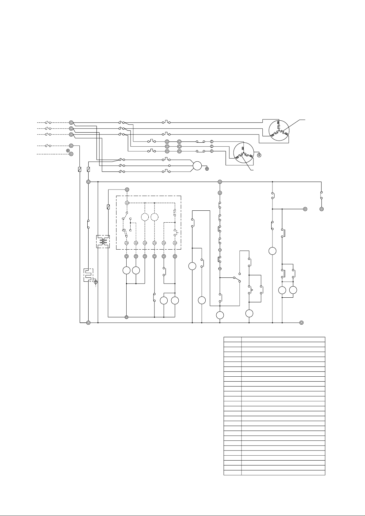
HZ
14
FZ0
FZ1
30
CZ
FZ0
30
CZ
30
CZ
FZ1
CZ
52C
(3MIN)
TM
52C
FZ1
CH
PRH-10YA,
PRH-10YA-L
···
60A
MF2
INTERNAL
PROTECTOR
11
PRH- 8YA,
PRH- 8YA-L
···
50A
8
51F1
CIRCUIT BREAKER
(FIELD SUPPLY)
MC
INTERNAL
PROTECTOR
C
51
1
51C
3
2
1
51F2
3
26L
23
WA
D1
26
CZ
WHITE
TB2
BLACK
RED
51F1
MF1
WHITE
RED
52F
TB2
X1
T1
T2
S1
S2
R1
R2
RED
RED
RED
WHITE
WHITE
BLACK
BLACK
BLACK
BLACK
F
52C
WHITE
(3.15A)
BLACK
WHITE
RED
BLACK
RED
BLUE
WHITE
RED
TB1
L1
L2
L3
N
PE
F
Power Supply
50Hertz
380~415Volt
3Phase
<SW3>
51C
MF2
<23WA>
30CZ
21S4
X1·2
51F1, 2
26D1·2
Name
Symbol
TM
Tr
TB1~4
<SW2>
HZ
FZ0·1
CZ
<SW1>
<RL>
<GL>
F
26L
CH
MC
MF1
52C
63H
52F
H
C
13
X2
26
D2
X2X1
X1
S4
21
52F
12
TB3
11
TB3
52C
CZ
TM
(3.15A)
F
SW1
HEAT
COOL
5
RL
51F2
AC
220~
240V
AC
24V
Tr
HZ
3
TB4
TB4
SWITCH BOX
(FIELD SUPPLY)
1
SW2
SW3
24 67
GL
HZ
63H
TB3
12
Note:
1.The dotted lines show field wiring.
2.The figure in the parentheses show field supply parts.
3.Color of earth wire is yellow and green twisting.
4.Not specified color of wire is brown.
5.Specification subject to change without notice.
Caution,
1.To protect each Fan motors and Compressors from abnormal current,
these Over current relays<51C>,<51F1,2>are installed.
Therefore,do not change factory set value of these Over current relays.
2.To protect the compressor from frequently "ON-OFF" ,timer<TM>is
installed. Therefore,do not change factory set value of this timer.
PRH- 5YA,
PRH- 5YA-L
···
40A
Thermostat(freeze protection)
Fan motor (in door)
Fuse
Transformer
Crankcase heater
Contactor (fan I/D)
Over current relay (fan I/D,O/D)
Contactor (compressor)
Fan motor (out door)
Over current relay(compressor)
Thermostat (defrost)
High-pressure switch
Terminal block
4-Way valve
Thermostat (room temp.)
Timer (anti short cycle)
Lamp (operation)
Lamp (check)
Switch (operation mode)
Switch (off)
Switch (on)
Auxiliary relay (check)
Auxiliary relay (heater)
Auxiliary relay (compressor)
Auxiliary relay (fan)
Auxiliary relay (defrost)
Compressor motor
15
8,10YA,
YA-L
ONLY
- 35 -
PRH-5, 8, 10YA
PRH-5, 8, 10YA-L (STANDARD)
Page 37
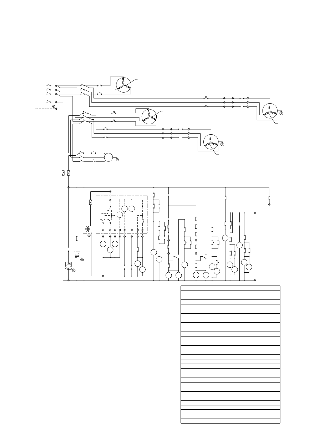
- 36 -
FZ0
X3
X1
2
GL
MF1
52
C2
52
C1
21
S41
21
S42
52
F
TM
CZ1
CZ2
FZ1
HZ
X4
X2
CZ2
FZ1
63
H2
51F3
3
1
51
26
C2
L2
CZ2-2
CZ1-2
30
FZ0
50Herts
380~415Volt
3Phase
Power supply
CH2
CH1
PRH-15YA
PRH-15YA-L
···100A
PRH-20YA
PRH-20YA-L
···125A
TM
(3MIN)
CZ2-1
30
FZ0
CZ1-1
30
L3
L2
L1
CIRCUIT BREAKER
(FIELD SUPPLY)
CZ2
L1
C1
26
51
1
3
51F2
H1
63
10
CZ2
30
CZ1
30
FZ1
D1
26
26
D3
51F3
51F2
52
52
C1
C2
RL2
RL1
Low
High
CZ2-1
CZ1-1
AC
24V
AC
220~
240V
Tr
HCHC
2345
6
8
97
1
HEAT
COOL
23WA
SWITCH BOX
(FIELD SUPPLY)
F
TB4 12
TB4 12
TB4 13
14
(2SEC)
C2C1
X1
X2
TB4 11
TB5
TB5
X1 X2
X2
26
D2
X4
CZ1
CZ1
SW3
SW2
SW1
52
52
2
30
30
1
2
3
51F1
HZ
HZ
F(3.15A)
F
(3.15A)
52F
51F1
51C1
51C2
52C1
52C2
N
TB1
TB2
TB3
21 22
21 22
21 22
T
TT
S
SS
R
RR
Blue
Black
Black
Black
Black
Black
Black
Black
Black
Black
Black
Black
White
White
White
White
White
White
White
White
White
White
Red
Red Red
Red
Red
Red
Red
Red
Red
Red
Red
Red
Red
Note:
1.The dotted lines show field wiring.
2.The figure in the parentheses show field supply parts.
3.Color of earth wire is yellow and green twisting.
4.Not specified color of wire is brown.
5.Specification subject to change without notice.
Caution,
1.To protect each Fan motors and Compressors from abnormal current,
these Over current relays<51C1,2>,<51F1,2,3>are installed.
Therefore,do not change factory set value of these Over current relays.
2.To protect the compressors from frequently "ON-OFF" ,timer<TM>is
installed. Therefore,do not change factory set value of this timer.
3.This timer<2>installed so that two compressors may never start at
the same time. The unit stop if the set value of the timer is changed.
INTERNAL
PROTECTOR
MF2
MF3
INTERNAL
PROTECTOR
MC1
INTERNAL
PROTECTOR
INTERNAL
PROTECTOR
MC2
C1
52
1
2
3
11 12
11 12
12
T
S
R
X3
11
Black
CZ1-2
30
CZ2-2
30
30
TM
(3MIN)
C2
52
26
D4
Thermostat(freeze protection)
26L1·2
Name
F
51C1·2
Tr
CH1·2
52F
51F1~3
52C1·2
MF2·3
MF1
MC1·2
26D1~4
63H1·2
TB1~5
Fan motor (in door)
Fuse
Transformer
Crankcase heater
Contactor (fan I/D)
Over current relay (fan I/D,O/D)
Contactor (compressor)
Fan motor (out door)
Over current relay(compressor)
Thermostat (defrost)
High-pressure switch
Terminal block
4-Way valve
Thermostat (room temp.)
Timer (anti short cycle)
Timer
Lamp (operation)
Lamp (check)
<23WA>
<RL1·2>
<GL>
TM
2
FZ0·1
21S41·42
<SW1>
<SW2>
<SW3>
30CZ1-1,2
HZ
CZ1·2
X1~4
Switch (operation mode)
Switch (off)
Switch (on)
Auxiliary relay (check)
Auxiliary relay (heater)
Auxiliary relay (compressor)
Auxiliary relay (fan)
Auxiliary relay (defrost)
Symbol
Compressor motor
30CZ2-1,2
Auxiliary relay (check)
PRH-15, 20YA
PRH-15, 20YA-L (STANDARD)
Page 38
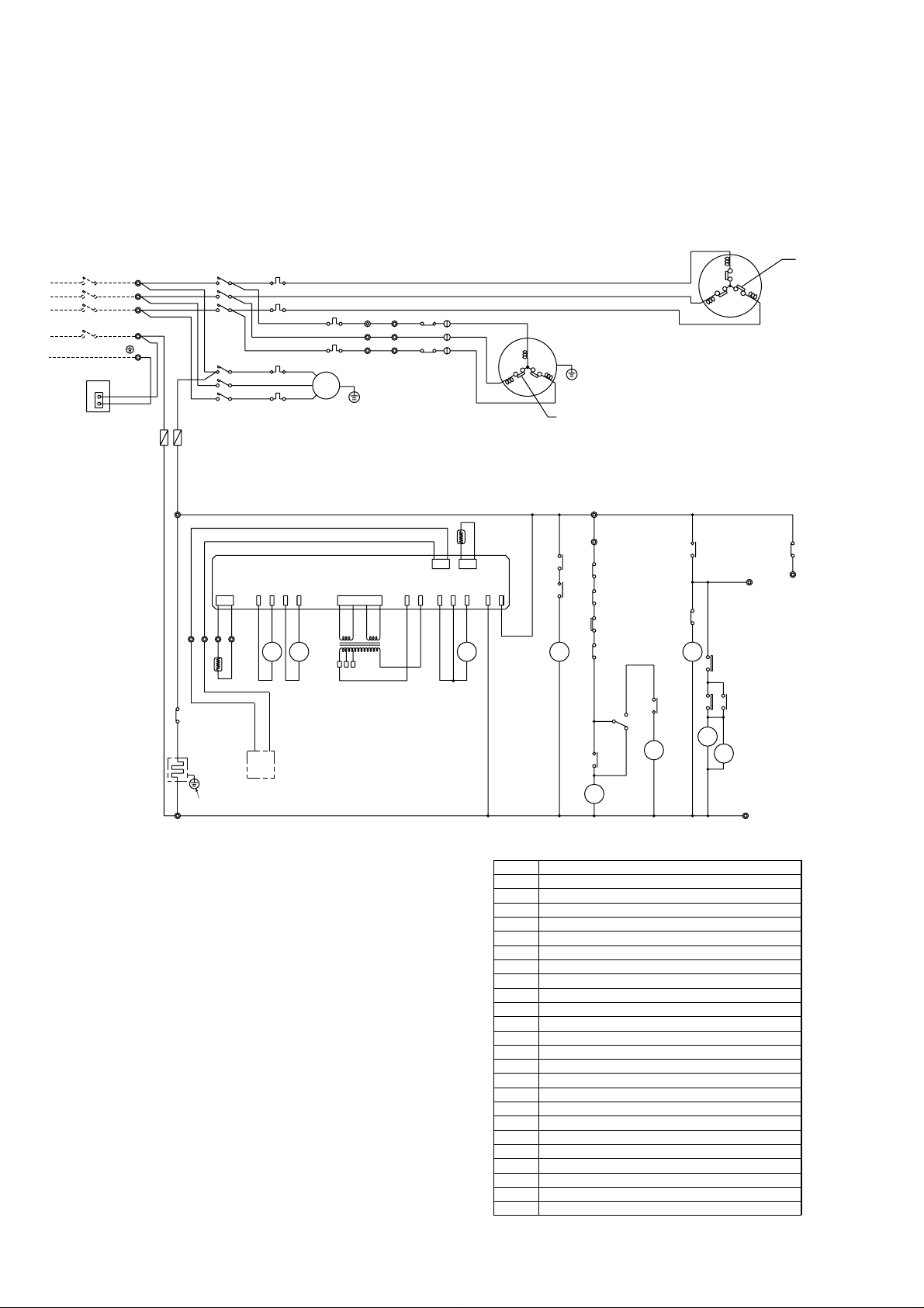
- 37 -
PRH- 8YA,
PRH- 8YA-L···50A
30
CZ
30
CZ
52C
CM
X1
X2
21
S4
30
CZ
MF1
52F
FZCZHZ
Over current relay(compressor)
High-pressure switch
Terminal block
Fuse
Transformer
Crankcase heater
Contactor(fan I/D)
Over current relay(fanI/D,O/D)
Contactor(compressor)
Fan motor(outdoor)
Fan motor(indoor)
Compressor motor
63H
TB1~4
51C
Surge absorber circuit boardDSA
R/C
TH5 Thermistor(room temp.)
Remote controller
4-Way valve
Thermistor(pipe)
Indoor board
FZ
Auxiliary relay(check)
Auxiliary relay(heater)
Auxiliary relay(compressor)
Auxiliary relay(fan)
Thermostat(defrost)
Auxiliary relay(defrost)
21S4
TH2
IB
30CZ
HZ
CZ
26D1·2
X1·2
Tr
F
CH
52F
51F1,2
52C
MF2
MF1
MC
Name
Symbol
14
HZ
DCBA
TB4
Green/Yellow
Blue
CN
DSA
3
1
CZ
FZ
CH
PRH- 5YA,
PRH- 5YA-L
···40A
15
3Phase
Power supply
TB1
L1
L2
L3
PE
380~415Volt
50Herts
N
CIRCUIT BREAKER
(FIELD SUPPLY)
51
51F1
63H
51F2
26
D1
X2
X1
D2
26
HZ
TH5
R/C
51F2
Red
White
Black
51C
Black
Red
Black
White
Red
3
2
1
13
TB3 12
TB3 12
X1
TB3 11
T
S
R
2
T
2
S
2
R
FZ
TH2
Tr
IB
52C
F(3.15A)
52F
51F1
52C
TB2
1
1
1
Black
Black
White
Blue
RedRed
Black
White
Red
MF2
INTERNAL
PROTECTOR
INTERNAL
PROTECTOR
MC
Note:
1.The dotted lines show field wiring.
2.The figure in the parentheses show field supply parts.
3.Color of earth wire is yellow and green twisting.
4.Not specified color of wire is brown.
5.Specification subject to change without notice.
Caution,
To protect each Fan motors and Compressor from abnormal current,
these Over current relays<51C>,<51F1,2>are installed.
Therefore,do not change factory set value of these Over current
relays.
PRH-10YA,
PRH-10YA-L···60A
11
8,10YA,YA-L ONLY
PRH-5, 8, 10YA
PRH-5, 8, 10YA-L
(SPECIAL ORDER : K CONTROL)
Page 39
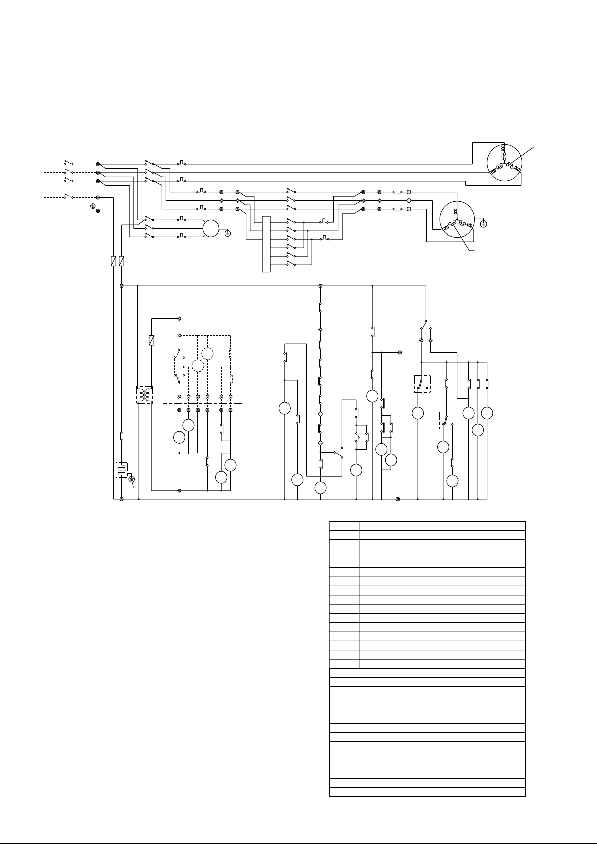
- 38 -
52C
30
CZ
30
CZ
C
21
S4
FZ1
FZ0
X1
X2
FZ4
FZ3
52F252
F4
52
F3
FZ2
52
F1
GL
RL
TM
MF1
CZ
HZ
Timer (anti short cycle)TM
<GL>
<RL>
Lamp (operation)
Lamp (check)
4-Way valve
Thermostat (room temp.)
<23WA>
Switch (on)
<SW2>
Switch (off)
<SW1>
21S4
30CZ
HZ
CZ
X1·2
Switch (operatin mode)
Auxiliary relay (check)
Auxiliary relay (heater)
Auxiliary relay (compressor)
Auxiliary relay (fan)
Auxiliary relay (defrost)
FZ0,1
Contactor (fan O/D)
Auxiliary relay (fan O/D)
FZ2~4
52F2~4
<SW3>
52F1
Thermostat(freeze protection)26L
Thermostat (defrost)
26D1~4
High-pressure switch63H
Name
F
51C
Tr1·2
CH
51F1,2,3
52C
MF2
MF1
MC
TB1~4
Fan motor (indoor)
Fuse
Transformer
Crankcase heater
Contactor (fan I/D)
Over current relay(fanI/D,O/D)
Contactor (compressor)
Fan motor (outdoor)
Over current relay(compressor)
Terminal block
Symbol
Compressor motor
15
11
12
51F3
HZ
14
16
FZ1
(3MIN)
TM
C
52
CZ
3
51
26L
1
51F2
63H
51F1
FZ1
FZ0
CZ
30
CH
PRH-10YA,
PRH-10YA-L
···60A
PRH- 8YA,
PRH- 8YA-L
···50A
(3.15A)
F
Power supply
3Phase
TB1
CIRCUIT BREAKER
(FIELD SUPPLY)
N
50Herts
380~415Volt
L3
L2
L1
8
D2
26
26
D1
X2
TB313
X1
HZ
3
FZ
FZ
2
4
FZ
2
FZ
3
FZ
26D4
26D3
51F2
White
51F3
X1
2
T
2
S
2
R
TB2
T
2
S
2
2
R
Black
Black
White
Red
Red
3
2
1
Black
Red
Tr1
52F4
52F3
TB2
R
S
T
1
1
1
52F2
Black
White
Red
T
S
R
1
1
1
CZ
AC
24V
AC
220~
240V
Tr2
HC
765432
1
HEAT
COOL
23WA
SWITCH BOX
(FIELD SUPPLY)
TB4
TB4
SW2
SW1
SW3
TB3 12
TB3 11
52C
F(3.15A)
52F1
51F1
51C
52C
Black
Black
Black
White
White
Blue
RedRed
Red
Black
White
Red
MF2
INTERNAL
PROTECTOR
INTERNAL
PROTECTOR
MC
Note:
1.The dotted lines show field wiring.
2.The figure in the parentheses show field supply parts.
3.Color of earth wire is yellow and green twisting.
4.Not specified color of wire is brown.
5.Specification subject to change without notice.
Caution,
1.To protect each Fan motors and Compressor from abnormal current,
these Over current relays<51C>,<51F1,2,3>are installed.
Therefore,do not change factory set value of these Over current relays.
2.To protect the compressor from frequently "ON-OFF",timer<TM>is
installed. Therefore,do not change factory set value of this timer.
PRH- 5YA,
PRH- 5YA-L
···40A
8,10YA,
YA-L ONLY
PE
PRH-5, 8, 10YA
PRH-5, 8, 10YA-L
(SPECIAL ORDER : LOW TEMPERATURE)
Page 40
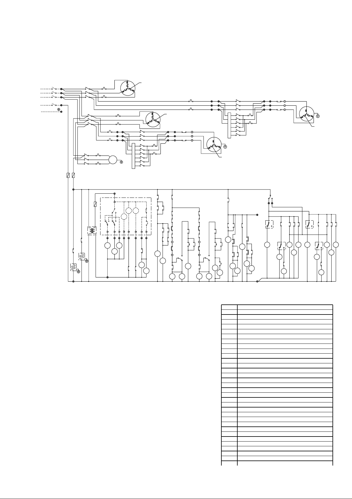
- 39 -
Note:
1.The dotted lines show field wiring.
2.The figure in the parentheses show field supply parts.
3.Color of earth wire is yellow and green twisting.
4.Not specified color of wire is brown.
5.Specification subject to change without notice.
Caution,
1.To protect each Fan motors and Compressors
from abnormal current,these Over current relays<51C1,2>,
<51F1~5>are installed.
Therefore,do not change factory set value of these Over current relays.
2.To protect the compressors from frequently "ON-OFF",timer<TM>is
installed. Therefore,do not change factory set value of this timer.
3.This timer<2>installed so that two compressors may never start at
the same time. The unit stop if the set value of the timer is changed.
C1
52
1
2
3
11 12
11 12
12
T
S
R
X3
11
Black
T
S
R
4-Way valve
Thermostat (room temp.)
Thermostat(freeze protection)
Timer (anti short cycle)
Timer
Lamp (operation)
Lamp (check)
26L1·2
<23WA>
<RL1·2>
<GL>
TM
2
Name
F
51C1·2
Tr1~3
CH1·2
52F1
51F1~5
52C1·2
MF2·3
MF1
MC1·2
FZ0·1
21S41·42
<SW1>
<SW2>
<SW3>
30CZ1-1, 2
HZ
CZ1·2
26D1~4
63H1·2
TB1~5
X1~4
Fan motor (indoor)
Fuse
Transformer
Crankcase heater
Contactor (fan I/D)
Over current relay (fan I/D,O/D)
Contactor (compressor)
Fan motor (outdoor)
Over current relay(compressor)
Switch (operation mode)
Switch (off)
Switch (on)
Auxiliary relay (check)
Auxiliary relay (heater)
Auxiliary relay (compressor)
Auxiliary relay (fan)
Thermostat (defrost)
High-pressure switch
Terminal block
Auxiliary relay (defrost)
Symbol
Compressor motor
Thermostat (ambiemt temp.)
FZ0
X3
X1
2
GL
MF1
52
C2
52
C1
21
S41
21
S42
52
F
TM
CZ1
CZ2
FZ1
HZ
X4
X2
CZ2
FZ1
63
H2
51F3
3
1
51
26
C2
L2
CZ2-2CZ1-2
30
FZ0
50Herts
380~415Volt
3Phase
Power supply
CH2
CH1
PRH-15YA
PRH-15YA-L
···100A
PRH-20YA
PRH-20YA -L
···125A
TM
(3MIN)
CZ2-1
30
FZ0
CZ1-1
30
L3
L2
L1
CIRCUIT BREAKER
(FIELD SUPPLY)
CZ2
L1
C1
26
51
1
3
51F2
H1
63
10
CZ2
30
CZ1
30
FZ1
D1
26
26
D3
51F3
51F2
52
52
C1
C2
RL2
RL1
Low
High
CZ2-1
CZ1-1
AC
24V
AC
220~
240V
Tr
HCHC
234568
97
1
HEAT
COOL
23WA
SWITCH BOX
(FIELD SUPPLY)
F
TB4 12
TB4 13
14
(2SEC)
C2C1
X1
X2
TB4 11
TB5
TB5
X1 X2
X2
26
D2
X4
CZ1
CZ1
SW3
SW2
SW1
52
52
2
30
30
1
2
3
51F1
HZ
HZ
F(3.15A)
F
(3.15A)
52F
51F1
51C1
51C2
52C1
52C2
N
TB1
TB2
TB3
22
22
22
T
T
S
S
R
R
Blue
Black
Black
Black
Black
Black
Black
Black
Black
Black
White
White
White
White
White
White
White
White
Red
Red Red
Red
Red
Red
Red
Red
Red
Red
Red
INTERNAL
PROTECTOR
MF2
MF3
INTERNAL
PROTECTOR
MC1
INTERNAL
PROTECTOR
INTERNAL
PROTECTOR
MC2
30
TM
(3MIN)
C2
52
26
D4
22
22
22
T
S
R
TB2
CZ1-2
30
CZ2-2
30
18
51F4 51F5
52
F3
52
F6
52
F4
52
F7
52
F2
52
F5
FZ4
FZ7
FZ3
FZ6
FZ2 FZ5
52F2~7
FZ2~7
26D1~4
Contactor (fan O/D)
Auxiliary relay (fan O/D)
TB4 12
36
25
47
25
3
6
FZ FZ
FZ FZ
FZ FZ
FZ FZ
FZ FZ
26D2
26D4
26D1
26D3
TB3
21
21
21
T
S
R
21
21
21
51F5
Red
White
Black
Tr2
52F7
52F5
Black
White
Red
52F6
11
11
11
T
S
R
51F4
Red
White
Black
Tr1
52F4
52F2
Black
White
Red
52F3
12
12
12
T
S
R
30CZ2-1, 2
Auxiliary relay (check)
TB4
PE
PRH-15, 20YA
PRH-15, 20YA-L
(SPECIAL ORDER : LOW TEMPERATURE)
Page 41
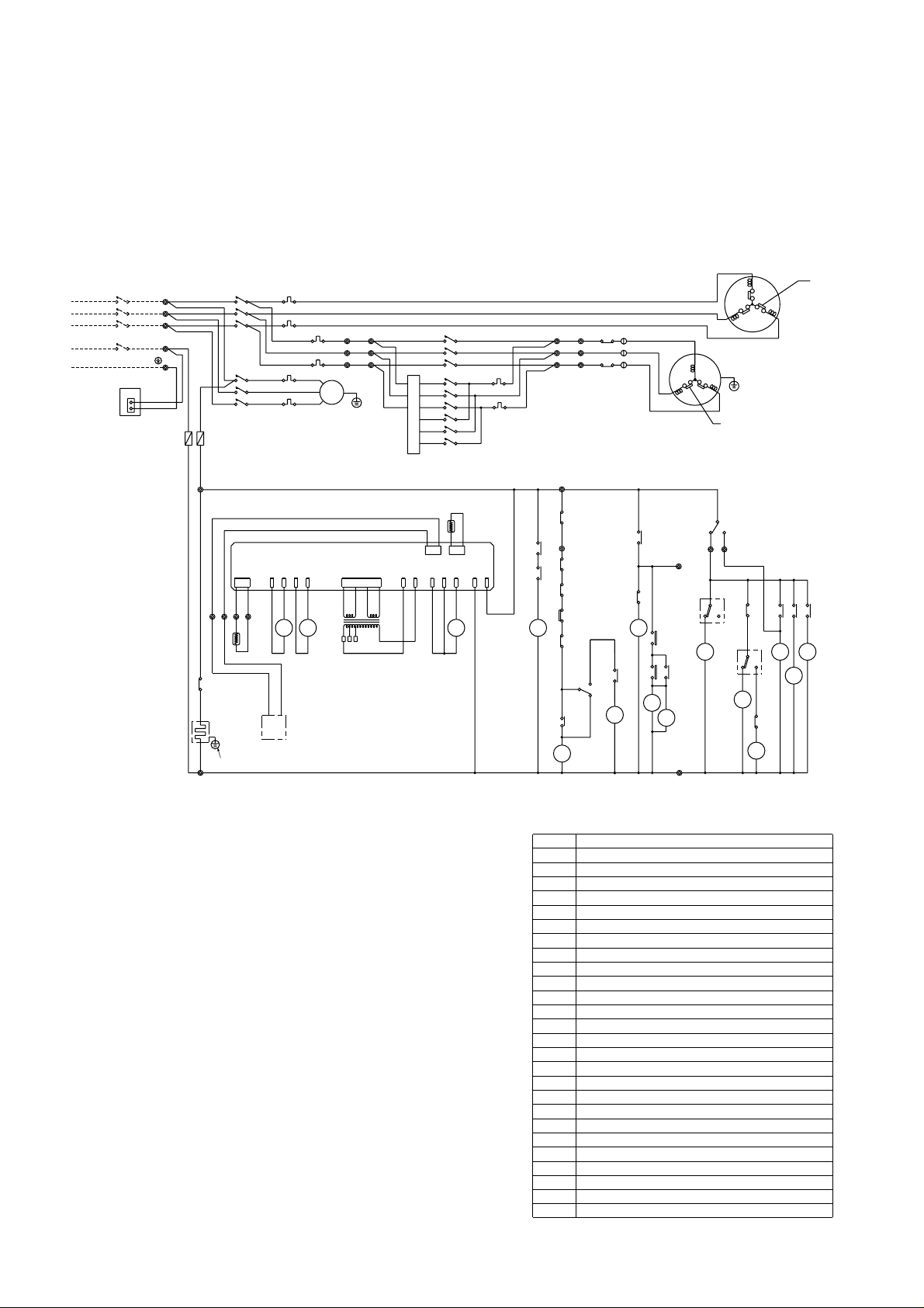
30
CZ
30
CZ
52C
30
CZ
C
FZ4
FZ3
52
F1
MF1
21
S4
52F252
F4
52
F3
FZ2
FZ1
X1
X2
CZ
HZ
Surge absorber circuit board
DSA
Thermistor(room temp)
TH5
Remote controller
R/C
FZ2~4
Auxiliary relay(fan O/D)
52F2~4
Contactor(fan O/D)
4-Way valve
Thermistor(pipe)
Indoor board
(compressor)
Over current relay
FZ1
Auxiliary relay(check)
Auxiliary relay(heater)
Auxiliary relay(compressor)
Auxiliary relay(fan)
Thermostat(defrost)
High-pressure switch
Terminal block
Auxiliary relay(defrost)
Fuse
Transformer
Crankcase heater
Contactor(fan I/D)
Over current relay(fanI/D,O/D)
Contactor(compressor)
Fan motor(outdoor)
Fan motor(indoor)
Compressor motor
21S4
TH2
IB
30CZ
HZ
CZ
26D1~4
63H
TB1~4
51C
X1·2
Tr1·2
F
CH
52F1
51F1,2,3
52C
MF2
MF1
MC
Name
Symbol
15
11
12
16
HZ
14
51F3
TB4
DCBA
Green/Yellow
Blue
DSA
CN
3
1
PRH- 10YA
PRH-10YA-L
···60A
PRH- 8YA,
PRH- 8YA-L
···50A
CIRCUIT BREAKER
(FIELD SUPPLY)
CZ
FZ1
CH
51F1
51F2
White
51F2
51F3
R/C
TH5
51
63H
3
FZ
FZ
2
Tr1
52F4
52F3
R
S
T
TB2
1
1
1
X1
2
T
2
S
2
R
TB2
T
2
S
2
2
R
52F2
Black
Black
Black
White
White
Red
Red
Red
3
2
1
TB3 13
TB3 12
TB3 11
T
S
R
4
FZ
2
FZ
3
FZ
26D4
26D3
X1
D2
26
26
D1
X2
FZ1
HZ
TH2
Tr2
IB
52C
F(3.15A)
52F1
51F1
51C
52C
N
PE
50Hertz
380~415Volt
3Phase
Power supply
L3
L2
L1
TB1
1
1
1
Black
Black
Black
Black
White
White
Black
Red
Red
RedRed
Blue
White
Red
MF2
INTERNAL
PROTECTOR
MC
INTERNAL
PROTECTOR
Note:
1.The dotted lines show field wiring.
2.The figure in the parentheses show field supply parts.
3.Color of earth wire is yellow and green twisting.
4.Not specified color of wire is brown.
5.Specification subject to change without notice.
Caution,
To protect each Fan motors and Compressor from abnormal current,
these Over current relays<51C>,<51F1,2,3>are installed.
Therefore,do not change factory set value of these Over current relays.
PRH- 5YA,
PRH- 5YA-L
···40A
8,10YA,YA-L ONLY
- 40 -
PRH-5, 8, 10YA
PRH-5, 8, 10YA-L
(SPECIAL ORDER : K CONTROL & LOW TEMPERATURE)
Page 42

- 41 -
ELECTRICAL OPERATION FLOW CHARTS
START
POWER ON
CH ON
CZ ON
TM ON
52C ON
MC OPERATE
MF2
OPERATE
CH OFF
30CZ OFF
RL ON
CH ON
52C OFF
MC STOP
MF2 STOP
SERVICE CALL
23WA ON?
PASS THE 3 MIN.?
SAFETY
DEVICE OFF?
YES
NO
YES
NO
YES
YES
GL ON
30CZ ON (SELF HOLD)
SW2 ON?
FZ0,1 ON
(SELF HOLD)
YES
52F ON
MF1 OPERATE
NO
NO
PR-5, 8, 10YC
Page 43

- 42 -
START
POWER ON
CH ON
52C ON
MC OPERATE
MF2 OPERATE
CZ ON
TM ON
52C ON
MC OPERATE
MF2
OPERATE
CH OFF
30CZ OFF
RL ON
CH ON
52C OFF
MC STOP
MF2 STOP
SERVICE CALL
HZ ON
21S4 ON
CZ ON
TM ON
CH OFF
26D1, 2 ON
X1 ON
X2 ON (SELF HOLD)
21S4 OFF
MF2 STOP
26D1, 2 OFF
21S4 ON
MF2 OPERATE
X1, 2 OFF
SW1 COOL?
23WA ON?
PASS THE 3 MIN.?
SAFETY
DEVICE OFF?
CONDENSING
TEMP. 6˚C?
CONDENSING
TEMP. -12˚C?
PASS THE 3 MIN.?
23WA ON?
NO
YES
NO
YES
NO
YES
YES
YES
YES
NO
NO
YES
NO
YES
GL ON
30CZ ON (SELF HOLD)
SW3 ON?
FZ0,1 ON
(SELF HOLD)
YES
52F ON
MF1 OPERATE
NO
NO
NO
<
=
<
=
PRH-5, 8, 10YA
PRH-5, 8, 10YA-L
Page 44

- 43 -
START
POWER ON
FZ0, FZ1 ON (SELF HOLD)
CH1, 2 ON
CZ1 ON
TM1 ON
52C1 ON
MC1 OPERATE
MF2 OPERATE
CH1 OFF
CZ2 ON
TM2 ON
CH2 OFF
30CZ1 OFF
RL1 ON
CH1 ON
52C2 ON
MC2 OPERATE
MF3 OPERATE
52C1 OFF
MC1 STOP
MF2 STOP
52C2 OFF
MC2 STOP
MF3 STOP
SERVICE CALL
CH2 ON
RL2 ON
30CZ2 OFF
52F ON
MF1 OPERATE
SW2 ON?
23WA No.1 ON?
PASS THE 3 MIN.?
23WA No.2 ON?
PASS THE 2 SEC.?
No.1 SAFETY
DEVICE OFF?
No.2 SAFETY
DEVICE OFF?
NO
YES
YES
NO
YES
NO
YES
NO
YES
NO
YES
YES
NO
YES
NO
GL ON
30CZ1, 30CZ2 ON (SELF HOLD)
PR-15, 20YC
Page 45

- 44 -
START
POWER ON
FZ0, FZ1 ON (SELF HOLD)
CH1, 2 ON
52C2 ON
MC2 OPERATE
MF3 OPERATE
CZ1 ON
TM1 ON
52C1 ON
MC1 OPERATE
MF2 OPERATE
CH1 OFF
CZ2 ON
TM2 ON
CH2 OFF
30CZ1 OFF
RL1 ON
CH1 ON
52C2 ON
MC2 OPERATE
MF3 OPERATE
52C1 OFF
MC1 STOP
MF2 STOP
52C2 OFF
MC2 STOP
MF3 STOP
SERVICE CALL
CH2 ON
RL2 ON
30CZ2 OFF
HZ ON
21S41, 2 ON
CZ1 ON
TM1 ON
TM2 ON
CH2 OFF
52C1 ON
MC1 OPERATE
MF2 OPERATE
CH1 OFF
26D1, 3 ON
X1 ON
X3 ON (SELF HOLD)
21S41 OFF
MF2 STOP
26D1, 3 OFF
21S41 ON
MF2 OPERATE
X1, 3 OFF
21S42 ON
MF2 OPERATE
X2 ON
X4 ON (SELF HOLD)
26D2, 4 ON
21S42 OFF
MF3 STOP
52F ON
MF1 OPERATE
SW3 ON?
SW1 COOL?
23WA No.1 ON?
PASS THE 3 MIN.?
23WA No.2 ON?
PASS THE 2 SEC.?
No.1 SAFETY
DEVICE OFF?
No.2 SAFETY
DEVICE OFF?
No.1 CONDENSING
TEMP. 6˚C?
No.1 CONDENSING
TEMP. -12˚C?
23WA No.1 ON?
PASS THE 2 SEC.?
PASS THE 3 MIN.?
23WA No.2 ON?
No.2 CONDENSING
TEMP. -12˚C?
No.2 CONDENSING
TEMP. 6˚C?
No.1 DEFROST
OPERATION?
NO
NO
YES
YES
NO
YES
NO
YES
NO
YES
NO
YES
YES
NO
YES
NO
YES
NO
YES
NO
YES
NO
YES
NO
NO
YES
NO
YES
NO
YES
NO
YES
NO
YES
GL ON
30CZ1, 30CZ2 ON (SELF HOLD)
<
=
<
=
<
=
<
=
PRH-15, 20YA
PRH-15, 20YA-L
Page 46

- 45 -
REFRIGERANT SCHEMATICS
Dryer
Strainer
Check
joint
ø19.05
Capillary
Tube
Check
joint
ø12.7
ø22.2
ø12.7
Check
joint
Check
joint
Pressure
gauge
High
pressure
switch
Compressor
Condenser
Evaporator
ø12.7
ø19.05
: OPTION
PR-5YC
Dryer
Strainer
Check
joint
ø19.05
Capillary
Tube
Check
joint
ø12.7
ø22.2
ø12.7
Check
joint
Check
joint
Pressure
gauge
High
pressure
switch
Compressor
Condenser
Evaporator
ø12.7
ø19.05
: OPTION
PR-8, 10, 15, 20YC
Notes: This schematics shows one refrigerant cycle.
PR-15,20YC or PRH-15,20YA or PRH-15,20YA-L is
composed of two refrigerant cycles.
Page 47

- 46 -
Dryer
Strainer Strainer
Check
joint
ø19.05
4-Way
valve
Capillary
Tube
Check
joint
Check
valve
ø12.7
ø22.2
ø12.7
Capillary
Tube
Check
joint
Check
joint
Pressure
gauge
High
pressure
switch
Compressor
Condenser
Evaporator
ø12.7
ø19.05
: OPTION
PRH-5YA
Dryer
Strainer Strainer
8, 15YA: ø22.0
10, 20YA: ø25.4
4-Way
valve
Capillary
Tube
Check
joint
Check
joint
Check
valve
ø15.88
ø12.7
ø25.4
ø12.7
Capillary
Tube
Check
joint
Check
joint
Pressure
gauge
High
pressure
switch
Muffler
Compressor
Condenser
Evaporator
ø15.88
8, 15YA: ø22.0
10, 20YA: ø25.4
: OPTION
PRH-8, 10, 15, 20YA
Notes: This schematics shows one refrigerant cycle.
PR-15,20YC or PRH-15,20YA or PRH-15,20YA-L is
composed of two refrigerant cycles.
Page 48
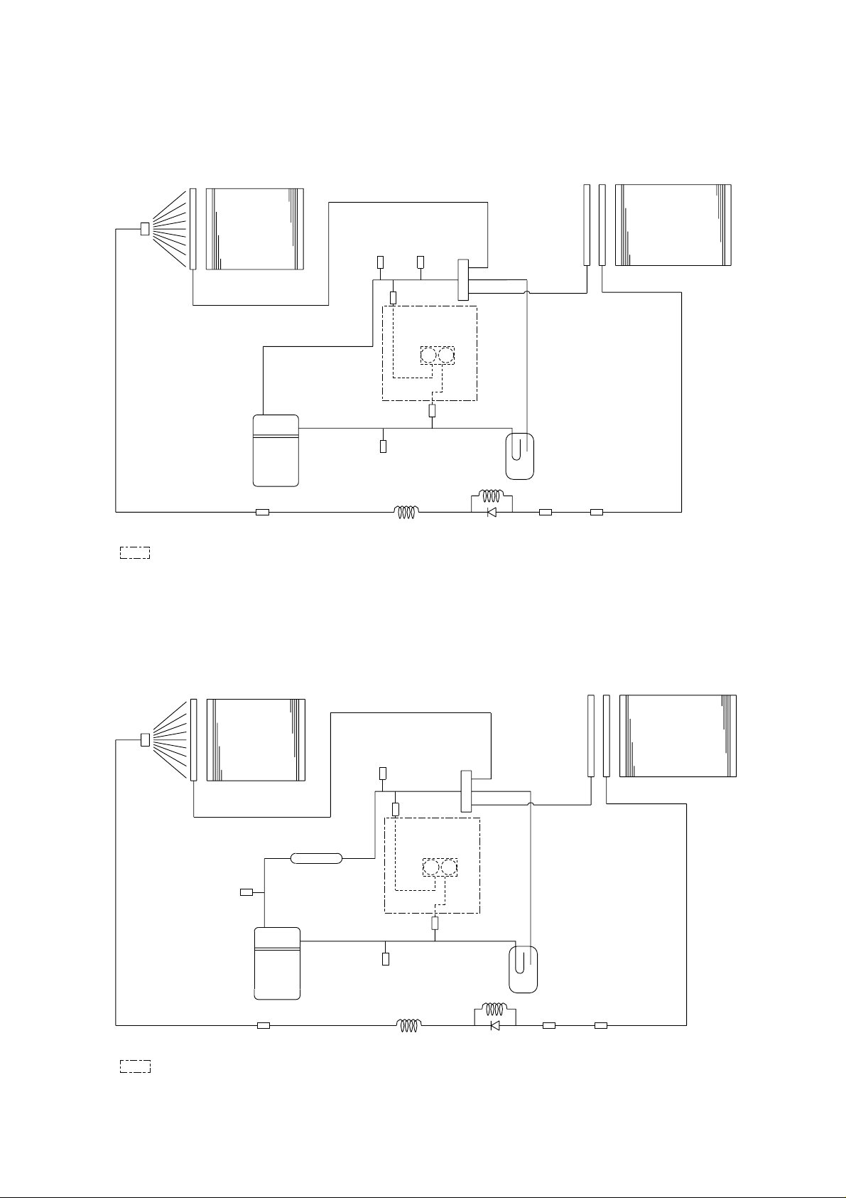
- 47 -
Dryer
Strainer Strainer
Check
joint
ø19.05
4-Way
valve
Capillary
Tube
Check
joint
Check
valve
ø12.7
ø22.2
ø12.7
Capillary
Tube
Check
joint
Check
joint
Pressure
gauge
High
pressure
switch
Compressor
Condenser
Evaporator
ø12.7
ø19.05
: OPTION
Accumulator
PRH-5YA-L
Dryer
Strainer Strainer
8,15YA-L: ø22.0
10,20YA-L: ø25.4
4-Way
valve
Capillary
Tube
Check
joint
Check
joint
Check
valve
ø15.88
ø12.7
ø25.4
ø12.7
Capillary
Tube
Accumulator
Check
joint
Check
joint
Pressure
gauge
High
pressure
switch
Muffler
Compressor
Condenser
Evaporator
ø15.88
8,15YA-L: ø22.0
10,20YA-L: ø25.4
: OPTION
PRH-8, 10,15,20YA-L
Notes: This schematics shows one refrigerant cycle.
PR-15,20YC or PRH-15,20YA or PRH-15,20YA-L is
composed of two refrigerant cycles.
Page 49
- 48 -
ACCESSORY AVAILABILITY
SAFETY & CONTROL DEVICES
ITEM NO.
COMPRESSOR OVER CURRENT RELAY 51C1,2 27.5A 31.0A
COMPRESSOR INTERNAL THERMOSTAT - 120
˚C
OFF 130˚C OFF
HIGH PRESSURE SWITCH 63H1,2 2.94MPa OFF
FREEZE PROTECTOR 26L1,2 -2
˚C
IN
FROST PROTECTOR
(ONLY PRH-YA,PRH-YA-L)
26D1,2,3,4 -12˚C IN, 6˚COUT
INDOOR FAN MOTOR OVER CURRENT RELAY 51F1 5.0A 6.6A
OUTDOOR FAN MOTOR OVER CURRENT RELAY 51F2,3 2.0A
OUTDOOR FAN MOTOR INTERNAL THERMOSTAT - 150
˚C
OFF
FUSE (CONTROL CIRCUIT) F 3.15A
FUSE (OPERATION CIRCUIT) F 3.15A
OUTDOOR FAN MOTOR OVER CURRENT RELAY
(USE THE OPTIONAL PARTS : LOW AMBIENT PARTS)
51F4,5 2.0A
ITEM NO.
PR-5YC
PRH-5YA
PRH-5YA-L
PR-8YC
PRH-8YA
PRH-8YA-L
PR-15YC
PRH-15YA
PRH-15YA-L
PR-20YC
PRH-20YA
PRH-20YA-L
PR-10YC
PRH-10YA
PRH-10YA-L
COMPRESSOR OVER CURRENT RELAY 51C 26.0A 27.5A 31.0A
COMPRESSOR INTERNAL THERMOSTAT - 110˚C OFF 120˚C OFF 130˚C OFF
HIGH PRESSURE SWITCH 63H 2.94MPa OFF
FREEZE PROTECTOR 26L -2˚C IN
FROST PROTECTOR (ONLY PRH-YA,PRH-YA-L) 26D1,2 -12˚C IN, 6˚C OUT
INDOOR FAN MOTOR OVER CURRENT RELAY 51F1 2.3A 3.2A 3.6A
OUTDOOR FAN MOTOR OVER CURRENT RELAY 51F2 2.0A
OUTDOOR FAN MOTOR INTERNAL THERMOSTAT - 150˚C OFF
FUSE (CONTROL CIRCUIT) F 3.15A
FUSE (OPERATION CIRCUIT) F 3.15A
OUTDOOR FAN MOTOR OVER CURRENT RELAY
(USE THE OPTIONAL PARTS : LOW AMBIENT PARTS)
51F3 2.0A
DESCRIPTION
MODEL NAME
PARTS CODE
PR-5YC PRH-5YA PRH-5YA-L PR-8YC PRH-8YA PRH-8YA-L PR-10YC PRH-10YA PRH-10YA-L
K-Remote controller
PR- YC-K
-- -- --
PRH- YA-K
------
PRH- YA-LK
-- - - - -
Low temperature cooling
PR- YC
PAC-201LC - - PAC-202LC - - PAC-203LC - -
PRH- YA
- PAC-201LC - - PAC-202LC - - PAC-203LC -
PRH- YA-L
- - PAC-201LC - - PAC-202LC - - PAC-203LC
Pressure gauge
PR- YC
PAC001PG - - PAC002PG - - PAC003PG - -
PRH- YA
- PAC001PG - - PAC002PG - - PAC003PG -
PRH- YA-L
- - PAC001PG - - PAC002PG - - PAC003PG
Fin guard
PR- YC
PAC101FG - - PAC102FG - - PAC103FG - -
PRH- YA
- PAC101FG - - PAC102FG - - PAC103FG -
PRH- YA-L
- - PAC101FG - - PAC102FG - - PAC103FG
DESCRIPTION MODEL NAME
PARTS CODE
PR-15YC PRH-15YA PRH-15YA-L PR-20YC PRH-20YA PRH-20YA-L
Low temperature cooling
PR- YC
PAC-201LCX2(PCS)
- - PAC-201LCX2(PCS) - -
PRH- YA
-
PAC-201LCX2(PCS) - - PAC-201LCX2(PCS) -
PRH- YA-L
-
- PAC-201LCX2(PCS) - - PAC-201LCX2(PCS)
Pressure gauge
PR- YC
PAC001PGX2(PCS)
-- PAC001PGX2(PCS) - -
PRH- YA
-
PAC001PGX2(PCS) - - PAC001PGX2(PCS) -
PRH- YA-L
-
- PAC001PGX2(PCS) - - PAC001PGX2(PCS)
Fin guard
PR- YC
PAC104FG
- - PAC105FG - -
PRH- YA
-
PAC104FG - - PAC105FG -
PRH- YA-L
-
- PAC104FG - - PAC105FG
:Factory install
:Field install
Page 50
- 49 -
PHYSICAL DATA
[PRODUCT]
ROOFTOP AIR-COOLED HEATPUMP PACKAGED AIR CONDITIONERS
Product type
PR,PRH,PRH-L SERIES
Product number : Cooling type
PR-5YC PR-8YC PR-10YC PR-15YC PR-20YC
Product number : Heat pump
PRH-5YA PRH-8YA PRH-10YA PRH-15YA PRH-20YA
Product number : Heat pump
PRH-5YA-L PRH-8YA-L PRH-10YA-L PRH-15YA-L PRH-20YA-L
Capacity kw
17.6 28.1 35.2 52.8 70.3
Cooling capacity (AS1861) kW
16.3 23.8 29.7 46.3 60.8
Sensible Cooling capacity (AS1861) kW
13 19.7 25.3 38.4 50.2
Cooling power consumption (Input) kW
5.4 8.3 11.4 16.8 22.7
ByPass Factor
0.19 0.24 0.18 0.18 0.11
Heating capacity (AS1861) (Only PRH-YA,PRH-YA-L)
kW
15.1 23 32 45.5 61.2
Heating power
consumption (Only PRH-YA,PRH-YA-L)
kW
4.6 7 9.6 14.4 19.3
[ELECTRICAL]
Design voltage Volts
415
Cycles Hz
50
Phases
3
Power supply Volts
415
Control voltage Volts
240/24
Maximum voltage Volts
415
Minimum voltage Volts
380
Approx. starting current Amps
62 87 100 115 135
Unit current (Nominal voltage and AS1861
maximum conditions)
Amps
12.8 20.6 25.7 37.9 50.9
Fan motor hp HP
1.0 1.5 2 3 4
Fan motor current Amps
2.26 2.90 3.28 4.72 6.06
Fan motor speed rpm
1,400 1,410 1,420
[COMPRESSOR]
Make
COPELAND
Model
CRNQ-0500-TFD QR90K1-TFD QR12M1-TFD QR90K1-TFD QR12M1-TFD
Type
HERMETIC LINE START (RECIPROCATING)
Quantity
11122
Nominal motor hp HP
5 7.5 10 2✕7.5 2✕10
Locked rotor current Amps
59.5 83.4 95.2 83.4 95.2
Normal run current (AS1861) Amps
7.65 11.7 15.62 2✕11.74 2✕15.22
Swept volume cc/rev
101.92 177.45 221.8 2✕177.45 2✕221.8
Bore mm
49.78 55.58
Stroke mm
26.19 18.29 22.86 18.29 22.86
Speed rpm
2,900
Number of cylinders
24
Oil charge m l
2,070 3,250 2✕3,250
Type of oil
Calumet R015 or Witco 3GS
Crankcase heater
watts
40 70 2✕70
[REFRIGERATION SYSTEM]
Refrigerant
R22
Refrigerant charge per circuit kg
3.6 4.6 5.8 2✕4.6 2✕5.8
Number of refrigerant controls
11122
Refrigerant control
Capillary tube
Reverse cycle valve (Only PRH-YA,PRH-YA-L)
4-Way valve
Defrost system (Only PRH-YA,PRH-YA-L)
Reverse cycle defrost
[EVAPORATOR]
Quantity
11122
Face area sq.m
0.53 0.69 2✕0.65
Rows deep
33434
Rows high
26 26 26 30 30
Finned length mm
800 1,046 2✕850
Face velocity m/s
1.7 2.0 2.4 2.2 2.4
Fins per meter
512 512 512 473 512
Fin material thickness mm
0.12
Fin material
Aluminium
Fins pitch mm
1.95 1.95 1.95 2.11 1.95
Tube diameter mm
9.52
Gauge of copper tube mm
0.35
Number of circuits
10 13 17 11 15
Page 51
- 50 -
[PRODUCT]
ROOFTOP PACKAGE AIR COOLED HEATPUMP AND COOLING ONLY UNITS
Product type
PRH SERIES
Product number : Heat pump
PRH-5YA PRH-8YA PRH-10YA PRH-15YA PRH-20YA
[INDOOR AIR CIRCUIT]
Number of blowers
12222
Diameter of blowers
mm
253 393
Width of blowers
mm
182 282
Blower drive
Belt drive
Fan motor output
kW
0.75 1.1 1.5 2.2 3.0
Normal fan motor run current
A
2.26 2.90 3.28 4.72 6.06
Air quantity
L/s
900 1,400 1,660 2,800 3,160
External static pressure
Pa
100 200
Supply air dimensions (h✕w)
mm✕mm
300✕850 300✕1,150 428 ✕1,820
Return air dimensions (h✕w)
mm✕mm
410✕900 410✕1,200 464 ✕1,879
[CONDENSER]
Quantity
11122
Face area
sq.m
1.3 1.12 1.46 2✕1.07 2✕1.32
Rows deep
33333
Rows high
30 23 30 30 37
Finned length
mm
1,700 1,920 2✕1,400
Face velocity
m/s
1.2 2.8 2.1 2.9 2.3
Fins per meter
473 473 473 473 473
Fin material thickness
mm
0.12
Fin material
Aluminium
Fins pitch
mm
2.11 2.11 2.11 2.11 2.11
Tube diameter
mm
9.52
Gauge of copper
tube mm
0.35
Number of circuits
11 11 15 11 14
[OUTDOOR AIR CIRCUIT]
Number of fans
11122
Diameter of fans
mm
600 800
Pitch of fans
mm
--- 990
Fan drive
Direct drive
Fan motor output
kw
0.15 0.35 0.35 2✕0.35 2✕0.35
Quantity
11122
Normal fan motor run current
Amps
0.6 1.3 1.3 2✕1.3 2✕1.3
Fan motor speed
rpm
650 645
Air quantity
L/s
1,583 3,083 2✕3,083
[ENCLOSURE AND FRAME]
height
mm
1,000 1,200
Dimension width
mm
1,000 1,300 1,990
depth
mm
1,600 1,840
Color
Munsell 5Y8/1
Panel thickness
mm
1.2
Condensate drain size
mm
25.4
Weight
kg
299 393 413 698 729
Sound power level
dbA
73 75 75 79 79
Sound pressure level
dbA
62 64 64 68 68
Page 52
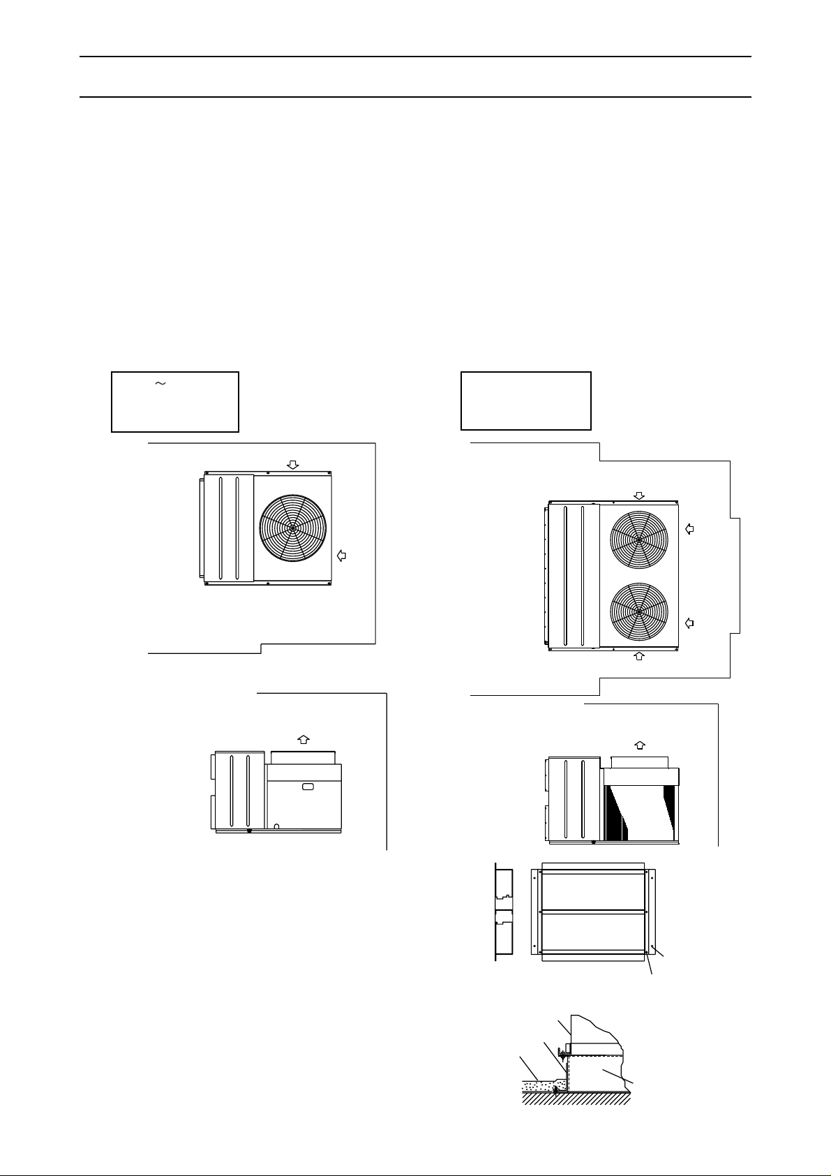
- 51 -
INSTALLATION
1.Clearances
300mm(min. clearance)
Condenser outlet
1,500mm(min. clearance)
1,000mm(min. clearance)
Evaporator coil service
1,000mm(min. clearance)
Evaporator coil service
300mm(min. clearance)
Condenser inlet
Condenser inlet
Condenser inlet
300mm(min.
clearance)
700mm(min. clearance)
Electrical
control circuit
and compressor
service
Condenser outlet
300mm(min.
clearance)
2.Roof Mounting
(1)The figure shows the use of the roof curb available
for mounting these units.
(2)The curb should be sealed and fixed to the roof by
weather stripping. A suggested means of sealing
the unit and roof curb is shown below.
Roof curb
Roof curb
6-ø15
Unit mounting holes
4-ø15roof mounting holes
Unit
Roof deck
Seal with tar
(1)Care must be taken to prevent recirculation of
the condenser air. To stabilize compressor
condensing pressures it is recommended that
wherever possible the condenser air inlet side
be faced away from prevailing winds.
(2)For rooftop installation, the type of mounting
base depends on the roof construction. A builtup roof may not support the weight of the unit
and so it may be necessary to support the unit
by adding structural members below it.
All series of air conditioners are designed for outdoor installations and are to be placed on a slab or
rooftop, however if the air conditioner is to be installed in a plant room application, please contact your
equipment supplier prior to installation.
Access for both service and installation must be provided to the compressors, control wiring and fans as
shown below.
(3)The units are equipped with hoisting
plates for rigging and hoisting of the unit.
The hoisting plates are located in the base
of the unit.
When hoisting the unit with a crane,
spreader bars must be used to prevent
damage to side panels by the supporting
cables.
1,500mm(min. clearance)
Condenser outlet
Evaporator coil service
1,000mm(min. clearance)
700mm(min. clearance)
Electrical
control circuit
and compressor
service
Condenser inlet
300mm(min. clearance)
300mm(min. clearance)
Condenser inlet
PR-5 10YC
PRH-5~10YA
PRH-5~10YA-L
PR-15,20YC
PRH-15,20YA
PRH-15,20YA-L
Page 53

- 52 -
3.Duct Work
(1)All series units are equipped with horizontal
supply and return air openings. Duct connection to
the unit should be made with duct flanges and
secured directly to the air openings with flexible
duct connectors to avoid normal noise transmission.
(2)For vertical air supply, a field supply plenum should
be used.
The figure below shows the recommended method
for duct connection.
(3)To prevent air leakage, all duct seams should be
taped.
Ducts run in air spaces that are not air-conditioned
must be insulated and provided with a vapor barrier.
Ducts exposed to the outside must be
weatherproofed. For quiet operation, we
recommend that the insulation on the supply duct
be placed inside, lining the duct.
(4)Where ducts from the outside enter a building, the
duct openings in the building should be sealed with
weather stripping to prevent rain, duct, sand,etc.
from entering the building.
(5) Correctly sized filters must be fitted and there is no
provision within the unit, however the filters may be
installed in the return air.
4.Drain piping
(1)A 1 FPT condensate drain fitting is provided. The
drain pipe can be led out at the right or left side.
Under standard specifications, it is led out at the left
side and the right side is covered.
(2)The drain pipe must be provided with a trap on the
outside of the unit and also installed at an incline for
proper drainage, as shown below.
(3)To prevent condensate formation and leakage,
provide the drain pipe with insulation to safeguard
against sweating.
(4)Upon completion of the piping work, check that there
is no leakage and that the water drains off properly.
Duct connection with a vertical air plenum
Insulation
Singleduct
divider
Duct
Duct
Roof line
Roof curb
Roof curb
Plenum
divider
Vertical air
plenum
PRH unit
B
AC
Drain trap for condensate
Note:ESP=External Static Pressure
The drain pipe
should extend
below this level.
Drain piping
Drain trap
A>70mm
B>2C
C>2XE.S.P
=
=
=
Page 54
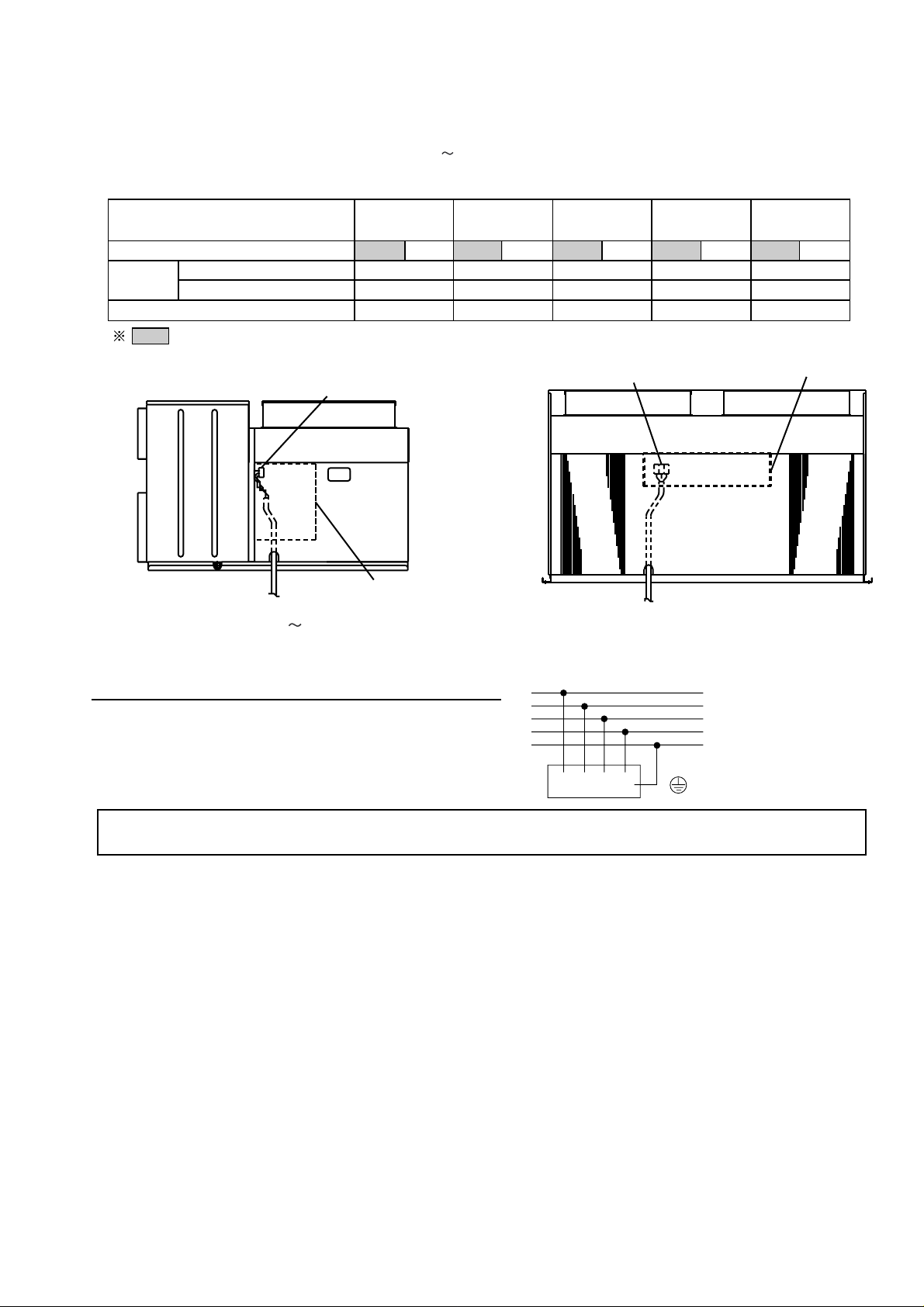
- 53 -
TN-NET SYSTEM (For European models only)
6.Final Checks
After having installed the unit, check that:
(1) The unit is fixed securely.
(2) The unit is installed properly.
(3) The drain pipe is provided with a drain trap.
(4) The electrical wiring has been connected correctly and the terminal screws have been properly
tightened.
(5) The duct work has been performed correctly.
7.Trial Operation
(1) Before turning the unit on, measure the resistance between the terminals of the electrical parts and
ground with a 500V megger and check that the value is at least 1MΩ. If the measured value is below 1MΩ,
do not operate the unit.
(2) Check the operation of the high pressure switch by activating it. Operation should stop when the two leads
of the outdoor unit fan motor are removed from the contactor and cooling continues for 5~10min.
(3) Check that the indoor and outdoor fans are rotating in the proper direction.
(4) After having checked the above points, proceed with a trial operation of the unit.
5.Electrical Wiring
Remove the panel on the right side (PR,PRH-5 10) or the rear side (PR,PRH-15,20) of the unit and
connect the units power supply wiring to the proper terminals in the control box, as shown below.
Wiring for PR,PRH-15,20(rear view)
power supply
Control box
Terminal block
MODEL
INDOOR FAN MOTOR OUTPUT
WIRING
POWER SUPPLY
EARTH
MAIN SWITCH
<kW>
<
mm
>
<
mm
>
< A >
2
2
PR-5YC
PRH-5YA
PRH-5YA-L
PR-8YC
PRH-8YA
PRH-8YA-L
PR-10YC
PRH-10YA
PRH-10YA-L
PR-15YC
PRH-15YA
PRH-15YA-L
PR-20YC
PRH-20YA
PRH-20YA-L
0.75 1.1
5.5
5.5
40
1.1 1.5
5.5
5.5
50
8
8
60
22
22
100
3.0 4.0
22
22
100
1.5 2.2 2.2 3.0
Std.
L1
L2
L3
N
PE
Note:
All electrical wiring must be comply with local electrical authority regulations.
Wiring for PR,PRH-5 10(right side view)
power supply
Control box
Terminal block
Page 55
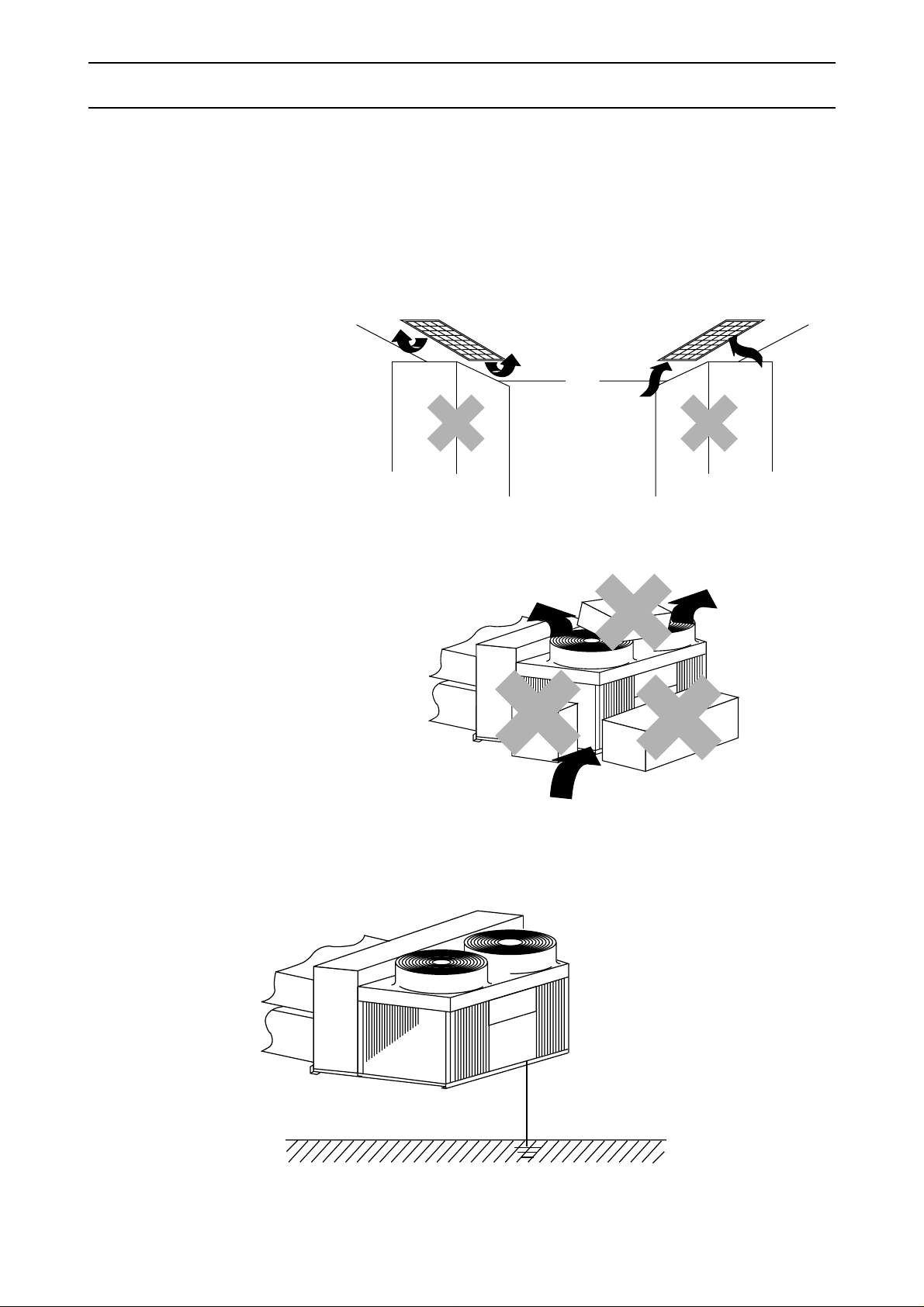
- 54 -
INSTRUCTIONS FOR USE
1.CHECK POINTS FOR OPERATION
Check the following points before you operate your air conditioner.
(1) Check that there is nothing blocking the flow of air from the air outlet into the air inlet.
(2) Make sure the air conditioner is properly grounded by checking the ground terminal .
Obstacle blocking air inlet
Ceiling
Inlet grille
Ceiling
Outlet grille
Obstacle blocking air inlet
Obstacle blocking air inlet
Ground
Indoor Unit
Outdoor Unit
Page 56

- 55 -
2.CAUTION FOR USE
Keep the following points in mind to safeguard against failures and breakdowns.
(1) This air conditioner does not restart within 3min.
after shut down.
(These models have a crankcase heater in the
compressor. If the air conditioner is shut down
for a short time, please do not turn the power
switch to OFF, but turn the operation switch to OFF.)
(2) If the air conditioner is shut down by a power failure,
set the operation switch to OFF. When the power is
restored, normal air conditioner operation can be
resumed.
(3) Do not stick rods or other objects through the air
outlet during operation since this may result in
equipment damage or personal injury.
Shutdown Operation
3 Minutes
3.MAINTENANCE
For superior performance and lasting durability, please do not forget to conduct
proper and regular maintenance.
3.1 Cleaning the Air Filter
Clean the air filter about once a week with a neutral cleanser and leave it to dry in a shady location. Clean
more regularly if the air filter gets very dirty.
If the filter gets blocked, air will not be sucked in properly, and the cooling effect will deteriorate. Failure to
clean the air filter may result in equipment breakdown or malfunctions.
3.2 Cleaning panels
Clean dirt off front panel as follows.
Use a household neutral cleanser such as for
dishes or vegetables. Moisten a soft cloth with
the cleanser, then wipe lightly. Next,wipe three
or four times with another soft cloth moisten
with water. Finally, wipe off all the remaining
cleanser with a soft cloth.
Moisten a soft cloth with the alcohol, then wipe
off lightly. Isopropyl alcohol is sold at stores as
reagents in small quantities.
3.3
Cleaning the Outdoor Unit Heat Exchanger
If you use your air conditioner for prolonged periods,
the outdoor heat exchanger will become dirty, impairing
its function and reducing air conditioners performance.
Consult your equipment supplier or air conditioning
contractor on how to clean the heat exchanger.
Fingermarks
Grease
Neutral
Cleanser
Heat exchanger
Heat exchanger
Note:
Alcohol is highly combustible. Take extreme
care when handling. Also, do not use paint or
adhesive thinner.
Adhesive
Paste
Isopropyl
alcohol
Page 57
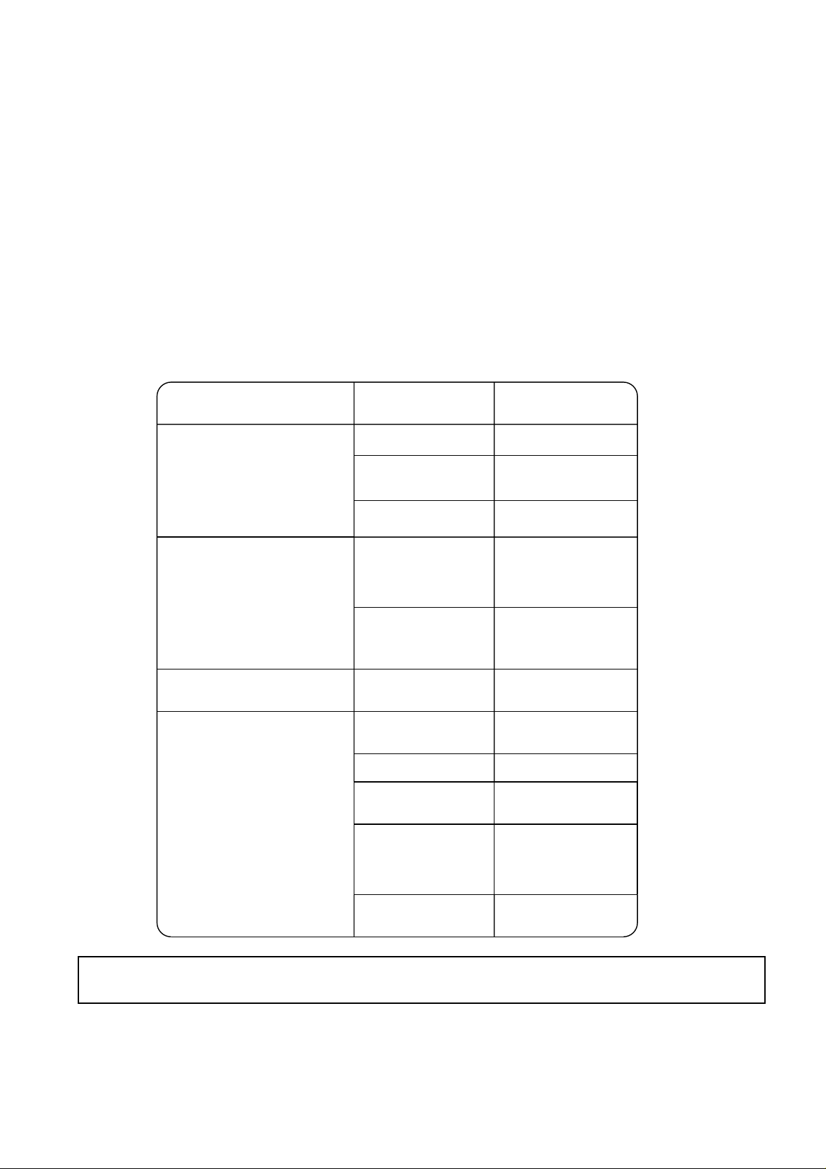
- 56 -
4. PREPARING FOR OPERATION AFTER PROLONGED SHUTDOWN
When the usage season starts, proceed with the following before starting operation:
(1)Clean the air filter.
(2)Do not use the unit immediately. Turn the main power switch on for a period of 3 hours before restarting
cooling / heating operation. This allows the compressors to come up to the correct operation temperatures.
Failure to do this, could cause compressor failure.
5.PREPARING FOR PROLONGED SHUTDOWN
After the usage season is over, prepare the air conditioner for later use by:
(1)Setting the power switch to OFF.
(2)Consulting your Air conditioning specialist for detailed information.
6.TROUBLESHOOTING
Note:
If the unit does not operate normally after troubleshooting, please contact your local equipment supplier or
air conditioning contractor.
Contact your
Air conditioning specialist
.
For temperature control,
• decrease the set
temperature at cooling.
• increase the set
temperature at heating.
The set temperature of
thermostat is
• excessively high for
cooling.
• excessively low for
heating.
Runs but without
cooling/heating.
Insufficient
refrigerant charge.
Remove blocking matter.Air outlet and inlet
are blocked.
Close them.Windows and doors are
being opened.
Clean it.The filter installed in
the field is clogged
with dust.
Fan runs but stops
immediately.
Remove blocking matter.Air outlet and inlet
are blocked.
Fan runs but compressor
does not run.
Can not be operated as
it is out of temperature
control range.
The room temperature is
• excessively low for
cooling.
• excessively high for
heating.
For temperature control,
• decrease the set
temperature at cooling.
• increase the set
temperature at heating.
The set temperature of
thermostat is
• excessively high for
cooling.
• excessively low for
heating.
Ask your electric power
company.
Excessively low power
source voltage.
Contact your
Air conditioning specialist
.
Blown fuse of power
source switch.
Wait for power supply
recovery.
Power failure.
Both fan and compressor
do not run.
RemedyPossible causeSymptom
If any trouble occurs, turn the operation (start or run) switch off immediately.
Page 58

- 57 -
SPECIFICATION GUIDELINES
Please supply and install a one piece, air to air reverse cycle air conditioning system.
The system shall be completely assembled, tested and have a complete refrigeration charge ready for
installation and operation from the factory.
The system shall operate at outdoor ambient temperatures as high as 46˚C.
The system shall have a total cooling capacity of kW or greater with an indoor air quantity of
L/s at ˚C db and ˚C wb entering indoor coil temperature with a ˚C temperature
entering
the outdoor coil.
The system shall have a sensible heat capacity of kW or greater with a room db temperature of
˚C.
The total heating capacity (without electric element heaters) shall be kW or greater at ˚Cdb,
˚C wb outdoor air conditions, with ˚C of indoor air entering indoor coil at ˚C db. One
kW electric heater element (accessory) shall be furnished.
The compressors shall be a welded high efficiency hermetic type with internal vibration isolation and be
equipped with a crankcase heater.
Compressors shall be protected by a factory installed anti-cycle device and provide a 3 minute delay before
compressor can restart.
Coils shall be of non-ferrous construction with mechanically bonded aluminium plate fins. Outdoor coils
shall be made, of 9.52mm OD, 0.35mm thick seamless copper tubes mechanically bonded to 0.12mm thick
aluminium plate fins.
Coils with multiple stage refrigeration systems shall consist of independent circuits. Face area of the coil
shall not be less than M2. The coil shall be factory pressure and leak tested at 3,233 kPa pressure.
The indoor coil face area shall be not less than M2.
Multi-wing propeller type fans shall be fitted at the condenser and shall be dynamically balanced, to ensure
smooth airflow and shall discharge vertically and be direct driven by a weatherproof three phase squirrel
cage kW induction motor.
The system shall be factory wired and all electrical wiring must comply with the Local wiring code. (Controls
and control wiring shall be supplied by the contractor). Compressors and fan motors shall have both internal
and current sensitive overload devices.
An automatic defrost control shall be included to accomplish defrosting (only if required) every
minutes for a period of minutes.
A low voltage transformer (24V) shall be factory installed in the unit for an external control circuit.
High pressure switch (pre-set) shall be factory installed.
The enclosure shall be a single, enclosed, weatherproof casing constructed of phosphatised, zinc coated
steel with acrylic resin primer and ivory white baked enamel finish.
The unit shall be provided with hoisting plates for rigging and hoisting the unit. The hoisting plates shall be
located in the base of the unit.
The unit shall have a 25mm OD male drain connection provided. The drain pipe shall be accessible from
either the left or right side of the unit. A blanking cap shall be provided to cap the drain outlet not being
used.
The duct (field supply) shall be fully insulated with fiber glass insulation to prevent sweating and to minimize
sound.
Each unit shall have a drain pan of 1mm thick steel coated with epoxy resin enamel.
The enclosure shall have openings provided for power connections. Access for both service and installation
shall be provided to compressors, control wiring, filters, electric heaters (when fitted) and fans.
Side panels and top panels shall be removable for easy service access.
The unit maximum dimensions shall be : height: mm, width: mm and depth: mm.
Due to continuous product development, these guidelines are subject to change.
Page 59

- 58 -
MEMO
Page 60

HEAD OFFICE DENKI BLDG., MARUNOUCHI,TOKYO 100,TELEX J24532 CABLE MELCO TOKYO
MITSUBISHI ELECTRIC CORPORATION
Issuued in January. 1999 MEE98K036
Printed in Japan.
New publication effective Jan. 1999.
Specifications subject to change without notice.
DATA BOOK PR,PRH
 Loading...