

Page 1
Introduction
WARNING
Information Provided by:
N09200102084
Thank you for buying a MITSUBISHI OUTLANDER.
We are confident you will enjoy your vehicle. It has been engineered
for optimum performance, durability and comfort. By thoroughly
reading this Owner’s Manual, you will gain an understanding of the
many features that are included in the OUTLANDER. The Owner’s
Manual contains descriptions and illustrations that will assist in the
operation and maintenance of your vehicle.
Throughout this manual the words WARNING and CAUTION
appear.
These are reminders to be especially careful. Failure to follow the
instructions could result in personal injury or damage to your vehicle.
Indicates a strong possibility of severe personal injury or death if
instructions are not followed.
Your Authorized Mitsubishi Motors Dealer will be happy to assist you
with any further questions you may have regarding the operation of
your vehicle.
Please note that this manual applies to all OUTLANDER models and
explains all features including options. Some features explained in this
manual may not be installed on your vehicle.
Please leave this Owner’s Manual in the vehicle at the time of resale.
The next owner will appreciate having access to the information contained here.
This manual includes instructions for standard and optional equipment
available at the time of printing. Mitsubishi Motors Corporation
reserves the right to make changes in design and specifications and to
make additions or improvements in its product without assuming any
obligation to install these on previously manufactured products.
Points out hazards or unsafe practices that could cause minor
personal injury or damage to your vehicle.
You will see another important symbol:
NOTE Gives helpful information.
As with other vehicles of this type, failure to operate this vehicle correctly may result in loss of control or an accident. Be sure to read
“on-pavement” and “off-road” driving guidelines in the “Driving
safety” and “Features and controls” sections.
Engine exhaust, some of its constituents, and certain vehicle compo-
nents contain or emit chemicals known to the State of California to
cause cancer and birth defects and reproductive harm. In addition,
certain fluids contained in vehicles and certain products of component wear contain or emit chemicals known to the State of California to cause cancer and birth defects or other reproductive harm.
©2014 Mitsubishi Motors Corporation Printed in Japan
Page 2
Table of contents
1
2
3
4
5
6
7
8
9
10
11
12
Information Provided by:
Overview
Quick index
General information
Seat and restraint systems
Features and controls
Driving safety
Comfort controls
For emergencies
Vehicle care and maintenance
Customer assistance/
Reporting Safety Defects
Specifications
Alphabetical index
Page 3
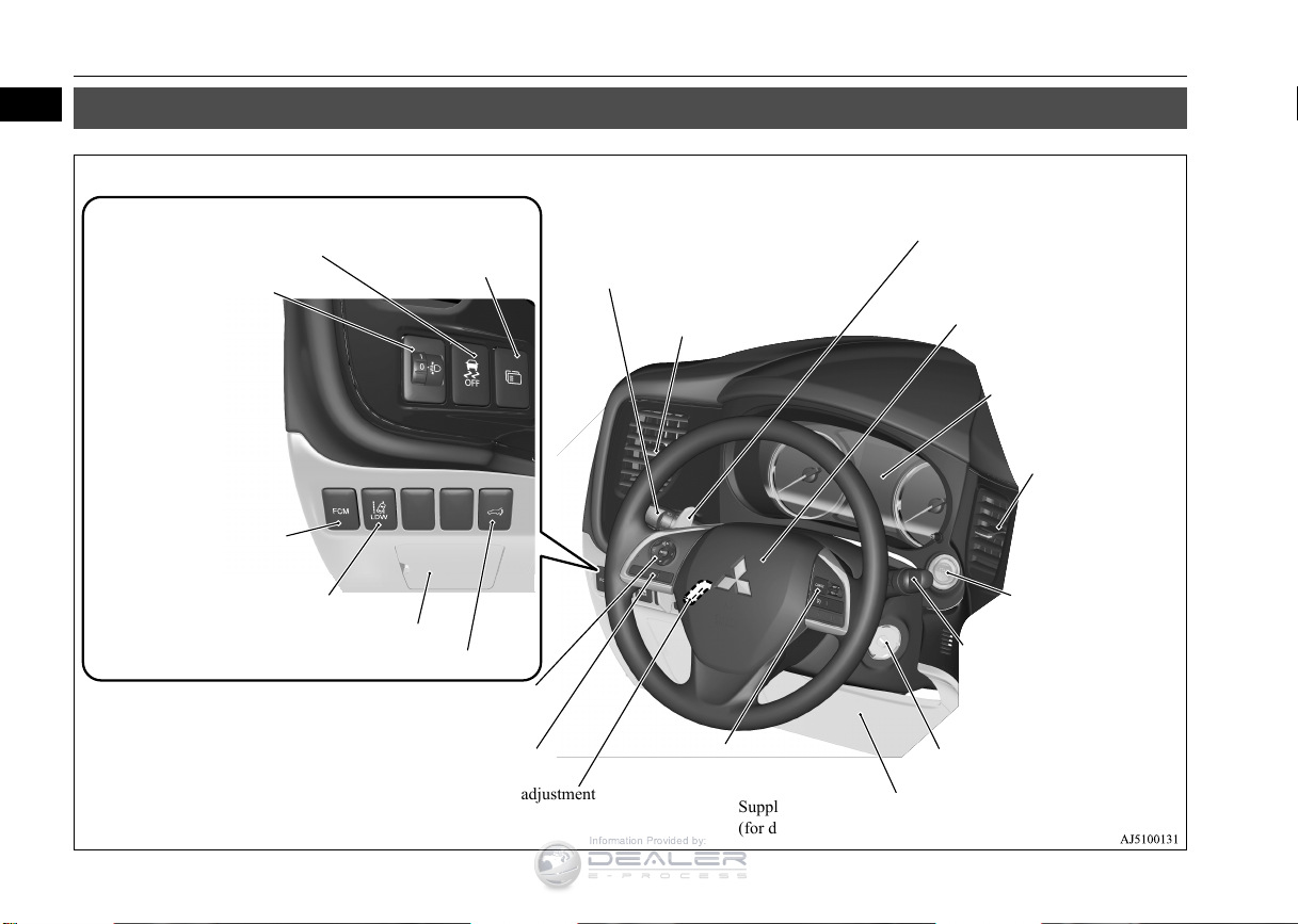
Instruments and controls
1
Combination headlights and dimmer
switch P.5-171
Turn signal lever P.5-176
Front fog light switch (if so equipped) P.5-178
Steering wheel audio remote control switches P.7-27
[For DISPLAY AUDIO and MMCS, refer to the separate
owner’s manuals.]
Active stability control (ASC) OFF
switch P.5-90
Supplemental restraint system
(SRS) - airbag (for driver’s
seat) P.4-33, 4-39
Horn switch P.5-184
Instrument cluster
P.5-120
Windshield wiper and washer
switch P.5-178
Rear window wiper and
washer switch P.5-182
Cruise control switch P.5-92
Steering wheel height and reach adjustment
lever P.5-53
Engine switch (if so
equipped) P.5-16
Bluetooth
®
2.0 interface (if so equipped)
P.5-185
Driver’s vents
P. 7 -2
Shift paddles (if so equipped) P.5-64
Driver’s vents
P. 7 -2
Multi information display
switch (if so equipped)
P.5-123
Headlight leveling switch
(if so equipped) P.5-176
Driver’s side power liftgate switch (if so equipped) P.5-38
Fuse box P.9-25
Lane departure warning (LDW) switch
(if so equipped) P.5-112
Forward collision mitigation
system (FCM) ON/OFF
switch (if so equipped)
P.5-109
Supplemental restraint system (SRS) - front knee airbag
(for driver’s seat) P.4-39
Ignition switch (if so equipped)
P.5-55
Information Provided by:
Instruments and controls
N00100202599
1-1
Overview
Page 4
1
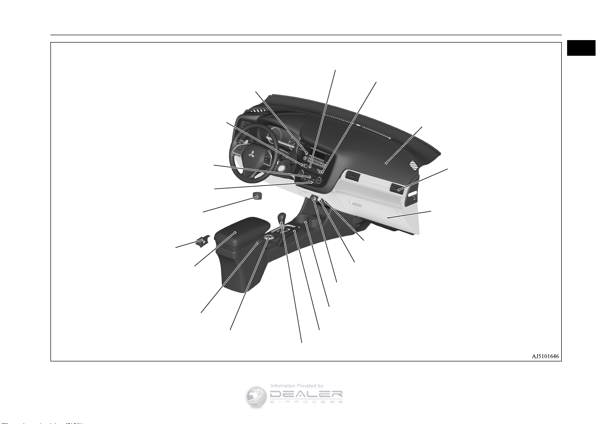
Audio (if so equipped) P.7-15
Mitsubishi Multi-Communication System (MMCS) (if so equipped)
[For DISPLAY AUDIO and MMCS, refer to the separate owner’s manuals.]
Hazard warning flasher switch
P.5-177
Electric rear window defogger switch P.5-183
Fuel tank filler door release lever
P. 3 -3
Drive mode selector (if so equipped) P.5-75
S-AWC drive mode-selector (if so equipped) P.5-78
Selector lever P.5-60, 5-67
Parking brake lever P.5-52
Supplemental restraint system (SRS) - air bag
(for front passenger’s seat)
P.4-33, 4-39
Air conditioner P.7-5
Hood release lever
P. 9 -3
Floor console box P.5-215
Arm rest
12 V power outlet P.5-210
USB input terminal
(if so equipped) P.5-206
Heated seat switch (if so equipped)
P. 4 -7
Cup holder P.5-217
12 V power outlet P.5-210
Power liftgate main switch (if so equipped)
P.5-37
Key slot (if so equipped)
P.5-25
Glove compartment P.5-214
Card holder P.5-214
Passenger’s vents
P. 7- 2
Passenger’s airbag off indicator P.4-38
Front passenger seat belt warning light
P.4-22
Information Provided by:
Instruments and controls
Overview 1-2
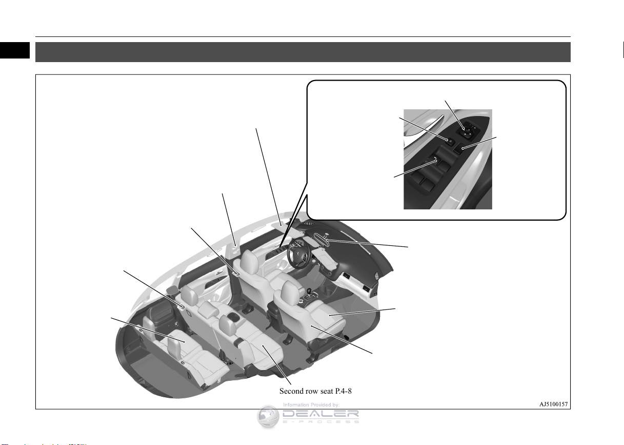
Page 5
1
Sun visors P.5-209
Vanity mirror P.5-209
Card holder P.5-209
Supplemental restraint system (SRS) - side airbag
(for front seats) P.4-44
Front seat P.4-4
Adjustable seat belt shoulder anchor P.4-23
Seat belts P.4-17
Cargo room light
P.5-213, 9-32
Electric remote-controlled outside rear-view mirrors switch P.5-54
Lock switch P.5-49
Power door lock
switch P.5-33
Power window switch
P.5-47
Second row seat P.4-8
Third row seat (7 persons)
P. 4- 1 0
Dome light (rear) P.5-212
Inside rear-view mirror
P.5-53
Information Provided by:
Interior
Interior
N00100302314
1-3 Overview
Page 6
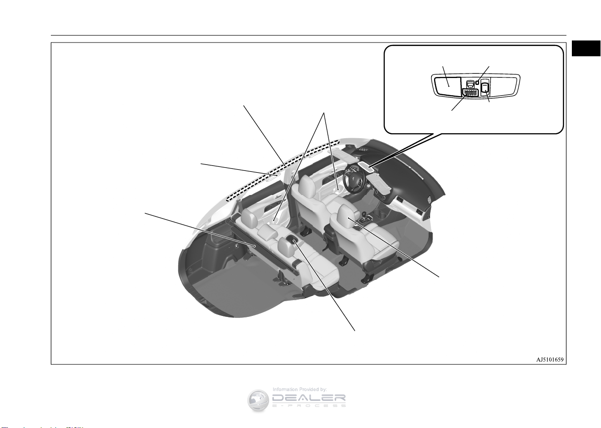
Interior
1
Assist grips P.5-220
Coat hook P.5-220
Bottle holder P.5-218
Sunroof switch
(if so equipped) P.5-50
Head restraints P.4-10
Arm rest P.4-9
Cup holder P.5-217
Cargo area cover (if so equipped)
P.5-218
Supplemental restraint system (SRS) - curtain
airbags P.4-44
Dome light (front)/Reading
lights P.5-211, 5-212
Downlight P.5-171
Hands-free microphone
(if so equipped) P.5-186
Information Provided by:
Overview 1-4
Page 7
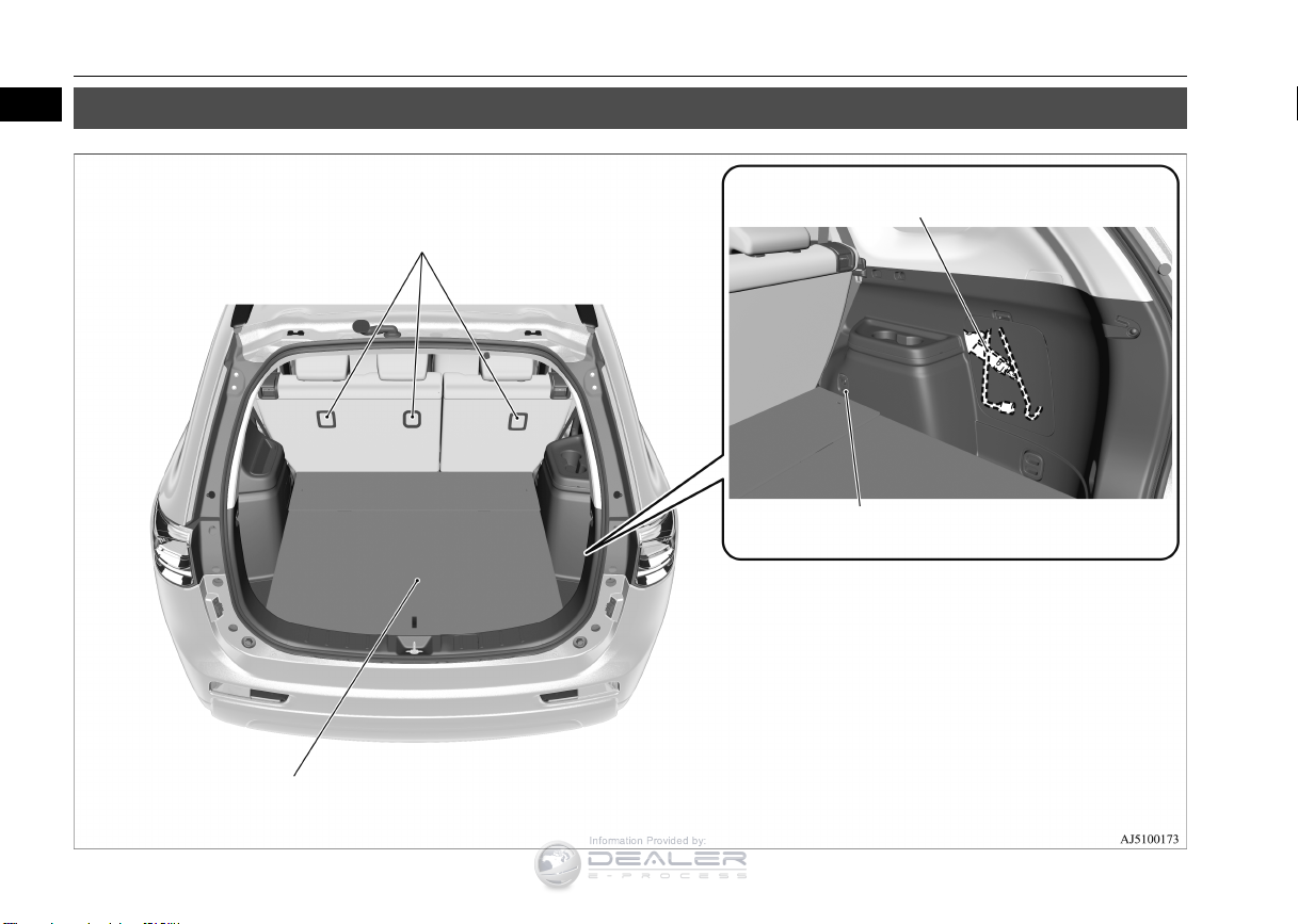
Luggage area
1
Jack P. 8-5
Tools P.8-5
Luggage hooks P.5-221
Luggage floor box P.5-215
Tether anchorages for child restraint system P.4-29
Information Provided by:
Luggage area
N00100501452
1-5 Overview
Page 8
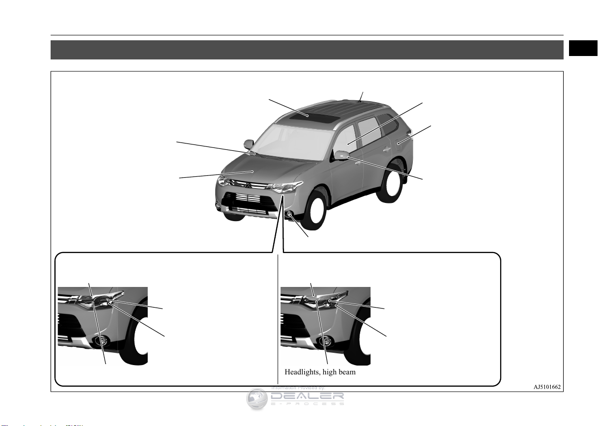
Outside (Front)
1
Sunroof (if so equipped) P.5-50
Windshield wipers P.5-178
Engine hood P.9-3
Front fog lights (if so equipped) P.5-178, 9-30, 9-35
Daytime running lights (if so equipped) P. 5-171, 9-30, 9-35
Outside rear-view mirrors P.5-54
Side turn-signal lights (if so equipped)
P.5-176, 9-30, 9-35
Fuel tank filler P.3-3
Power window P.5-47
Front turn-signal lights P.5-176, 9-30, 9-35Front turn signal lights P.5-176, 9-30, 9-35
Headlights, low beam
P.5-174, 9-30, 9-33
Parking lights P.5-171, 9-30, 9-34
Headlights, low beam/Daytime
running lights P.5-171, 5-174,
9-30, 9-32
Parking lights
P.5-171, 9-30, 9-34
Headlights, high beam P.5-174, 9-30, 9-33 Headlights, high beam P.5-174, 9-30, 9-33
Except for high intensity discharge headlights type High intensity discharge headlights type
Front side-marker lights P.5-171,
9-30, 9-33
Front side-marker lights
P.5-171, 9-30, 9-33
Information Provided by:
Outside (Front)
N00100602476
Overview 1-6
Page 9
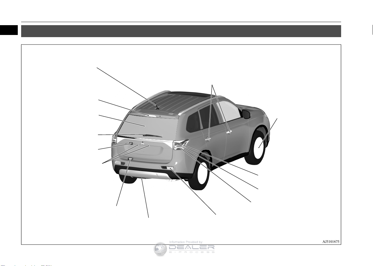
Outside (Rear)
1
Keyless entry system (if so equipped) P.5-7, 5-28
F.A.S.T.-key (Free-hand Advanced Security Transmitter) (if so equipped)
P.5-12
Locking and unlocking P.5-31
Tire P.9-14
Tire pressure monitoring system P.5-114
Tire inflation pressures P.9-18
Changing tires P.8-6
Tire rotation P.9-20
Tire chains P.9-21
Size of tires and wheels P.11-7
Tail and stop lights
P.5-171, 9-30, 9-36
Rear turn signal lights P.5-176, 9-30, 9-36
Spare tire P.8-7
Back-up lights P.9-30, 9-37
License plate lights
P.5-171, 9-30, 9-38
Rear-view camera (if so equipped)
P. 5 -1 1 8
Rear window wiper
P.5-182
High-mounted stop light
P.9-30
Antenna P.7-47
Liftgate (if so equipped) P.5-35
Power liftgate (if so equipped)
P.5-36
Power liftgate close switch (if so
equipped) P.5-38
Rear side-marker lights P.5-171, 9-30
Information Provided by:
Outside (Rear)
N00100602489
1-7 Overview
Page 10
2
If this warning light comes on or flashes while you’re driving...
NOTE
Information Provided by:
If this warning light comes on or flashes while you’re driving...
N00200702159
For information regarding warning displays in the multi-information display (Color liquid crystal display type), refer to “Multi-information display” on
page 5-122.
These warning lights will come on for a few seconds for a bulb check when the ignition switch is first turned to “ON” or the operation mode is put in ON.
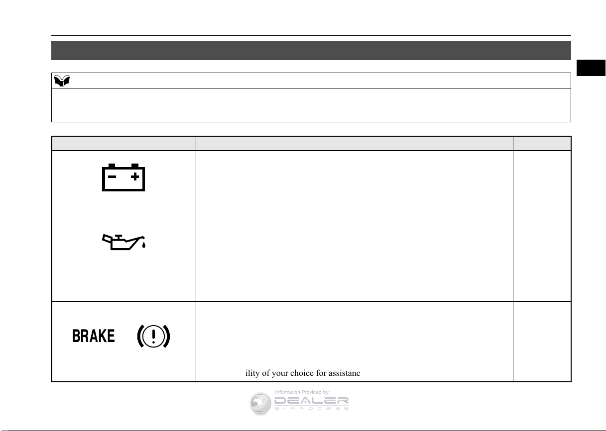
Warning lights Do this Ref. Page
Park your vehicle in a safe place and stop the engine.
Charging system warning light
Oil pressure warning light
(Vehicles equipped with mono-color
liquid crystal display)
or
Brake warning light
Contact your Mitsubishi Motors dealer or a repair facility of your choice for assistance.
Park your vehicle in a safe place and stop the engine, then check the engine oil
level.
If the light comes on while the engine oil level is normal, have the system checked
at an authorized Mitsubishi Motors dealer or a repair facility of your choice as soon
as possible.
If this light comes on while driving, check to see that the parking brake is fully
released.
If this light stays on after releasing the parking brake, immediately stop and check
the brake fluid level.
If the brake fluid level is correct, there may be a system malfunction. Avoid hard
braking and high speed, and contact an authorized Mitsubishi Motors dealer or a
repair facility of your choice for assistance.
P. 5-168
P. 5-168
P. 5-167
Quick index
2-1
Page 11
If this warning light comes on or flashes while you’re driving...
2
Information Provided by:
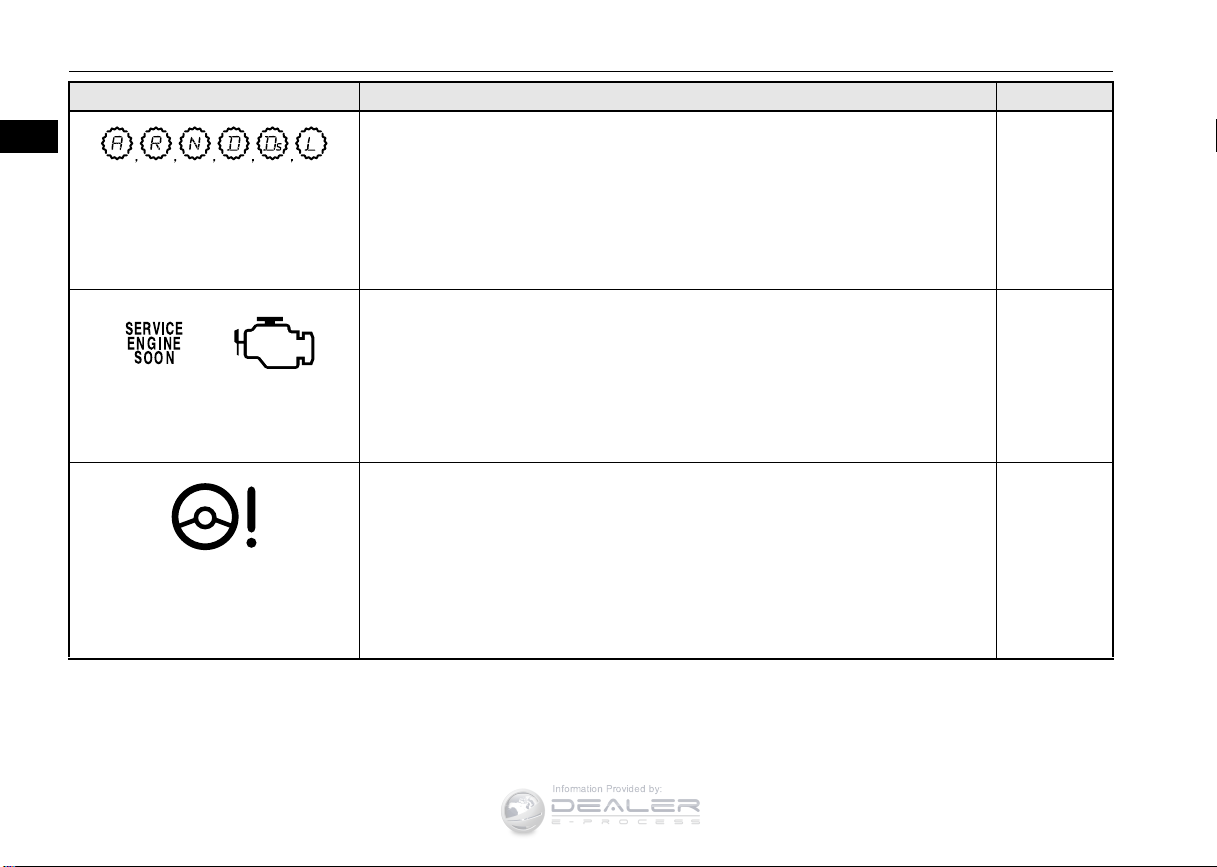
Warning lights Do this Ref. Page
Selector lever position indicator in the
instrument cluster flashes rapidly
(Vehicles equipped with mono-color
Electric power steering system (EPS)
(Vehicles equipped with mono-color
(once per second)
liquid crystal display)
or
Engine malfunction indicator
(“SERVICE ENGINE SOON” or
“Check engine light”)
warning light
liquid crystal display)
Park your vehicle in a safe place.
Idle the engine until the selector lever position indicator stops flashing.
If the indicator does not go off, have the system checked at an authorized Mitsubishi Motors dealer or a repair facility of your choice as soon as possible.
Although your vehicle will usually be drivable and not need towing, have the
engine system checked at an authorized Mitsubishi Motors dealer or a repair facility
of your choice as soon as possible. If the vehicle is not drivable, contact emergency
roadside assistance at 1-888-648-7820 (for vehicles sold in U.S.A.) or 1-888-5764878 (for vehicles sold in Canada), an authorized Mitsubishi Motors dealer, or local
towing company for assistance.
If this light comes on while the engine is running, it may become harder to turn the
steering wheel. Have your vehicle inspected at an authorized Mitsubishi Motors
dealer or a repair facility of your choice as soon as possible.
P. 5-62,
5-69
P. 5-167
P. 5-88
2-2 Quick index
Page 12
If this warning light comes on or flashes while you’re driving...
2
Information Provided by:
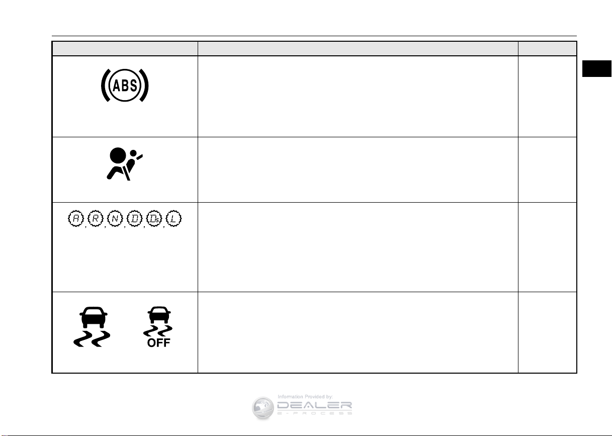
Warning lights Do this Ref. Page
When this light comes on, the anti-lock braking system is not functioning and only
the ordinary braking system is functioning.
Park your vehicle in a safe place and stop the engine.
Test the system as described on page 5-87.
Anti-lock braking system warning
light
If the light does not go out after the test, or if it comes on again, we recommend that
you have the system checked at an authorized Mitsubishi Motors dealer or a repair
facility of your choice as soon as possible.
P. 5-87
SRS warning light
Selector lever position indicator in the
instrument cluster flashes slowly
(once every 2 seconds)
(Vehicles equipped with mono-color
liquid crystal display)
and
ASC indicator and ASC OFF indicator
Immediately have the airbag and the pre-tensioner seat belt system checked at an
authorized Mitsubishi Motors dealer.
Have the automatic transaxle checked at an authorized Mitsubishi Motors dealer or
a repair facility of your choice as soon as possible.
Park your vehicle in a safe place and stop the engine.
Restart the engine and check whether the indicator goes out.
If the indicator does not go out, or if it comes on again, have your vehicle inspected
by an authorized Mitsubishi Motors dealer or a repair facility of your choice as soon
as possible.
When this indicator comes on, the active stability control is not functioning and
normal operation of the vehicle will not be affected.
Quick index 2-3
P. 4-39
P. 5-62,
5-69
P. 5-91
Page 13
If this warning light comes on or flashes while you’re driving...
2
Information Provided by:
Warning lights Do this Ref. Page
Park your vehicle in a safe place and stop the engine.
Restart the engine and check whether the indicator goes out.
If the indicator does not go out, or if it comes on again, have your vehicle inspected
by an authorized Mitsubishi Motors dealer or a repair facility of your choice as soon
as possible.
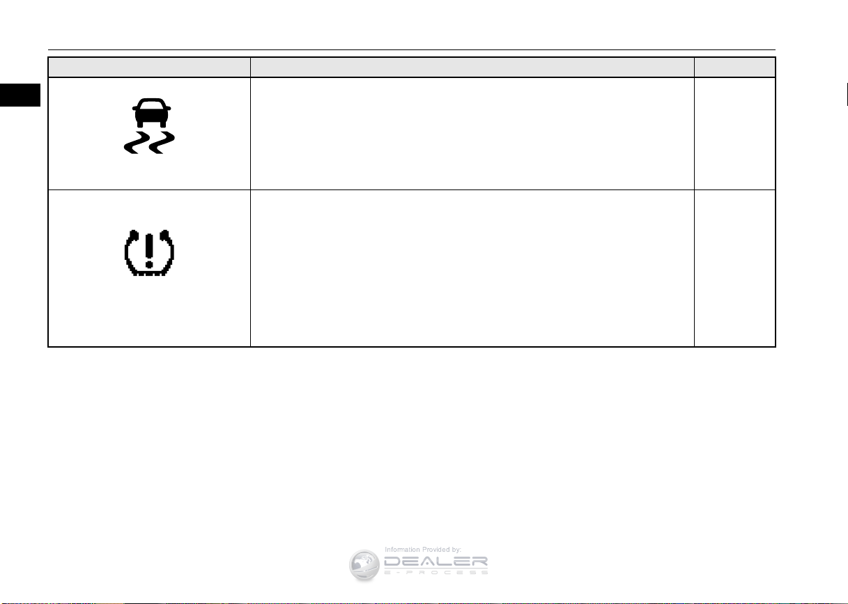
Tire pressure monitoring system warn-
ASC indicator
ing light
When this indicator comes on, the hill start assist is not functioning.
Start off carefully on a steep uphill slope.
If the warning light comes on, you should stop and adjust the tires to the proper
inflation pressure as soon as possible.
(See “Tire inflation pressures” on page 9-18.)
Once adjustments have been made, the warning light will go off after a few minutes
of driving.
If the warning light blinks for approximately 1 minute and then remains continu-
ously illuminated, the system is not operating properly. If the system returns to normal, the warning light will go off. If the warning light does not go off, have the
vehicle inspected at an authorized Mitsubishi Motors dealer.
P. 5-85
P. 5- 11 4
2-4 Quick index
Page 14
If this problem occurs...
2
Information Provided by:
If this problem occurs...
N00200901880
Problem Do this Ref. Page
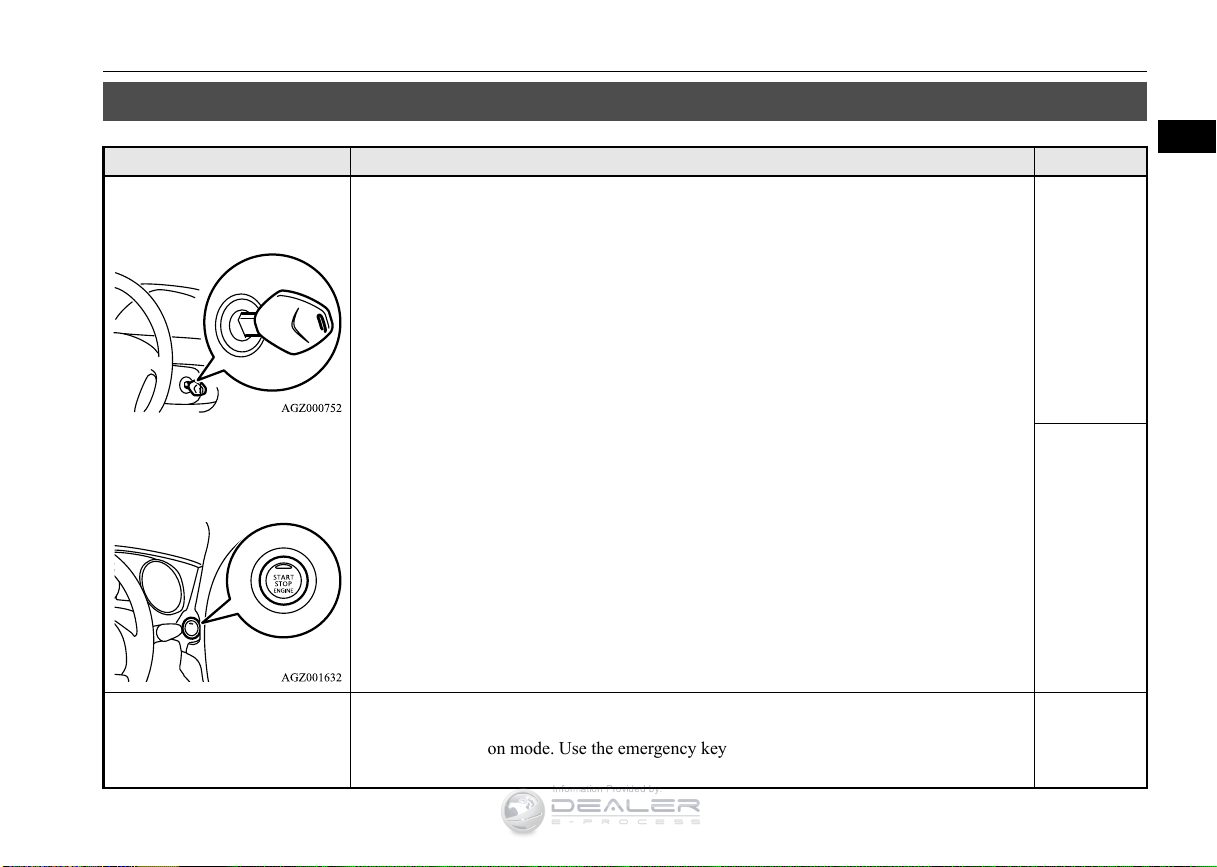
Unable to turn the key.
(except for vehicles equipped
with the F.A.S.T.-key)
The engine does not start when
the engine switch is pressed.
(for vehicles equipped with the
F.A. S. T.- ke y)
Will not turn from “LOCK” to “ACC”. (Vehicles with steering lock system)
Turn the key while turning the steering wheel in either direction.
Will not turn from “ACC” to “OFF” or “LOCK”.
Check the position of the selector lever.
The key cannot be removed unless the selector lever is set to the “P” (PARK) position.
On vehicles with steering lock system, push the key in at the “ACC” position and keep it
depressed until it is turned to the “LOCK” position.
Make sure the F.A.S.T.-key is in the vehicle.
Make sure the selector lever is in the “P” (PARK) position, and then press the engine switch
while depressing the brake pedal.
P. 5-57
P. 5-56
P. 5-23
The F.A.S.T.-key does not operate.
(for vehicles equipped with the
F.A. S. T.- ke y)
Insert the F.A.S.T.-key into the key slot of the instrument panel, and then start the engine or
change the operation mode. Use the emergency key to lock and unlock the driver’s door.
Quick index 2-5
P. 5-25,
5-25
Page 15
If this problem occurs...
2
Information Provided by:
Problem Do this Ref. Page
Cannot shift the selector lever
from the “P” (PARK) position.
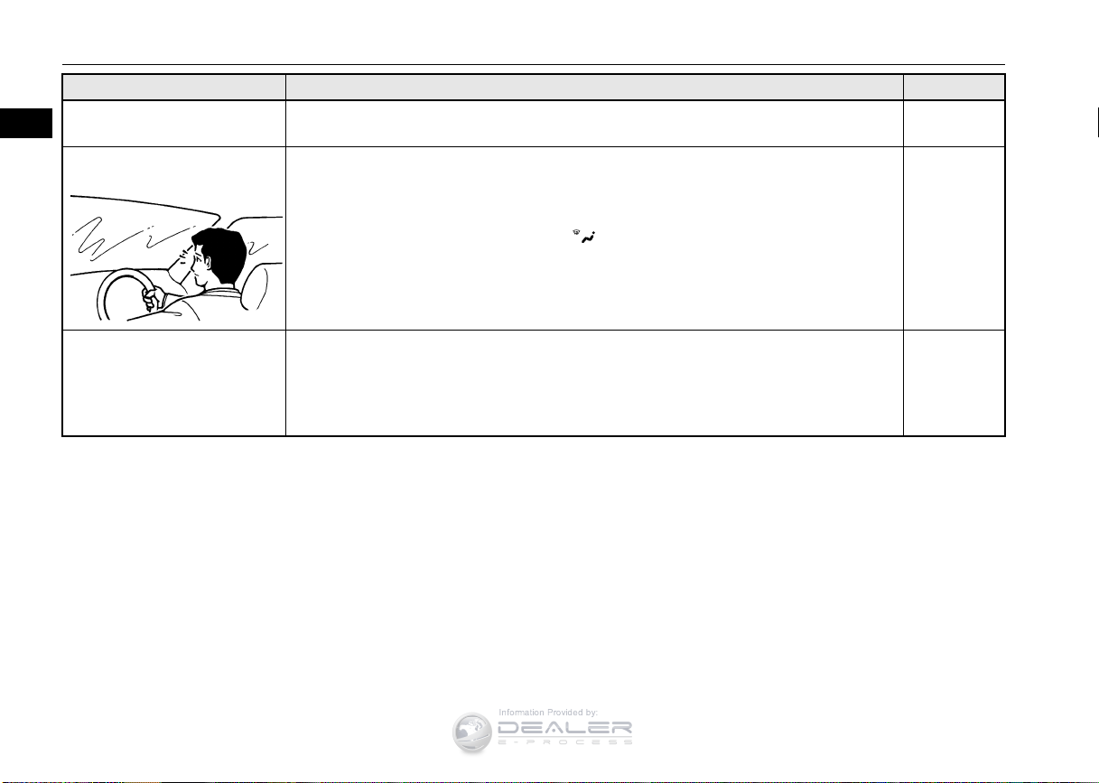
The windows are fogged up.
Shift the selector lever while pressing the brake pedal.
Check that the ignition switch or the operation mode is in ON.
P. 5-60
The engine does not start.
The lights do not come on.
The lights are dim.
The horn does not honk.
The horn sound is weak.
2-6 Quick index
Push the defogger switch to change to the “ ” position.
Have the battery checked. Recharge or replace as needed.
P. 7-9
P. 8-2,
9-13
Page 16
If this problem occurs...
2
Information Provided by:
Problem Do this Ref. Page
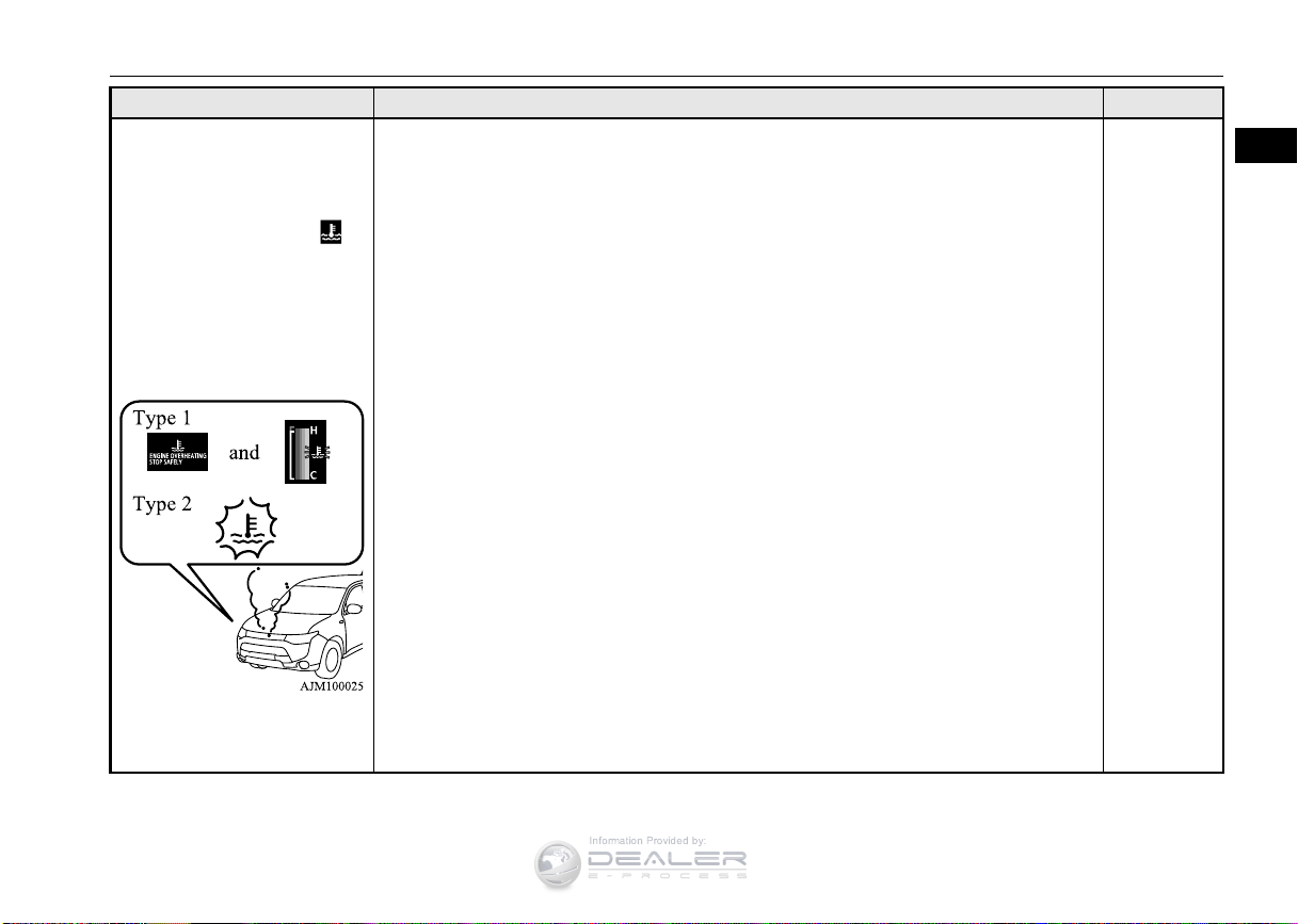
The information screen in the
multi information display will
be interrupted and the engine
coolant temperature warning
display will appear. Also “ ”
will blink. (Type 1: Color liquid
crystal display type)
The high coolant temperature
warning light will illuminate.
(Type 2: Mono-color liquid
crystal display type)
Steam comes out of the engine
compartment.
The engine is overheated.
Carefully stop the vehicle in a safe place.
P. 8- 4
Quick index 2-7
Page 17
If this problem occurs...
2
WARNING
Information Provided by:
Problem Do this Ref. Page
1. Slowly press down on the accelerator pedal to get your vehicle moving again. For an all-
If your vehicle becomes stuck in
sand, mud or snow
wheel drive vehicle, set the drive mode-selector to the “4WD AUTO” or “4WD LOCK”
position and then slowly press down on the accelerator pedal to get your vehicle moving.
2. If there is nothing to stop your tires from slipping, rock your vehicle out of the stuck position.
When attempting to rock your vehicle out of a stuck position, be sure that no one is near the vehicle. The rocking motion may cause the vehicle to
suddenly lurch forward or backward, possibly injuring bystanders.
Avoid revving the engine or spinning the wheels. Prolonged efforts to free a stuck vehicle may result in overheating and transaxle failure.
If the vehicle remains stuck after several rocking attempts, have a towing service pull the vehicle out.
Problem Do this Ref. Page
The brakes are not functioning
properly after crossing a puddle
or stream.
The automatic transaxle makes
no gear change when accelerating. The initial movement of the
vehicle is slow when the vehicle
starts moving.
(for vehicles with automatic
transaxle)
Dry out the brakes by driving slowly while lightly pressing the brake pedal.
There may be a problem in the automatic transaxle.
Have the system inspected by your authorized Mitsubishi Motors dealer or a repair facility of
your choice.
P. 8-15
P. 5-82,
6-5
P. 5-66
2-8 Quick index
Page 18
If this problem occurs...
2
Information Provided by:
Problem Do this Ref. Page
The continuously variable transmission (CVT) makes no shift
change when accelerating. The
initial movement of the vehicle
is slow when the vehicle starts
moving.
(for vehicles with CVT)
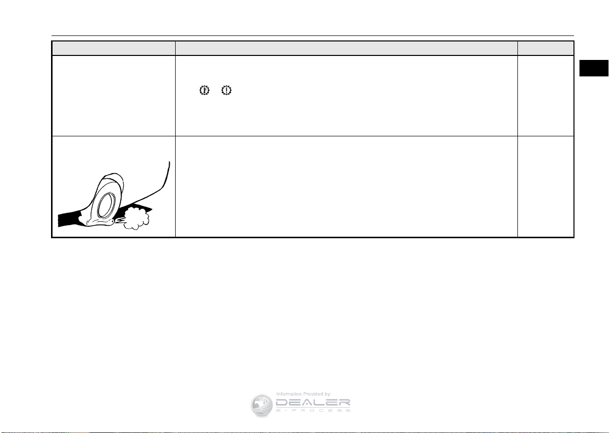
A tire is punctured.
There may be a problem in the CVT.
If the or warning lights on the multi-information display (Color liquid crystal display
type) will not turn off, or if they come on frequently, please have the vehicle checked at your
nearest Mitsubishi Motors dealer.
P. 5-73
1. Park the vehicle in a safe place where the surface is flat and level.
2. Replace the flat tire with the spare tire.
P. 8- 6
Quick index 2-9
Page 19

Information Provided by:
Page 20
3
General information
Information Provided by:
Fuel selection ...................................................................................3-2
Filling the fuel tank ..........................................................................3-3
Modifications to and racing of your vehicle ....................................3-5
Genuine Mitsubishi Motors parts ....................................................3-6
California Perchlorate Materials Requirements ...............................3-7
Page 21
Fuel selection
3
WARNING
CAUTION
Information Provided by:
Fuel selection
Your vehicle is designed to use unleaded gasoline only. It is equipped with a fuel tank
filler pipe specifically designed to accept only
a small diameter unleaded gasoline dispensing nozzle.
Gasoline is highly flammable and explo-
sive. You could be burned, seriously
injured or killed when handling it. Whenever you refuel your vehicle, stop the
engine and keep flames, sparks, and
smoking materials away from the vehicle.
Always handle fuel in well-ventilated outdoor areas.
Using leaded gasoline in your vehicle will
damage the engine, catalytic converter, and
the oxygen sensors. Also, using leaded gasoline is illegal, and will void your warranty
coverage of the engine, catalytic converter,
and oxygen sensors.
Gasoline detergent additives
In the United States, fuel suppliers are
required by law to add detergents to their gas-
N00301001922
oline to minimize fuel-injector clogging and
minimize intake-valve deposits. Detergent
gasoline helps keep your engine in tune and
your emission-control system working properly.
Octane requirement
2.4 liter engine model
Your vehicle is designed to operate on
unleaded gasoline having a minimum octane
number of 87 [(MON+RON)/2] or 91 RON.
3.0 liter engine model
Unleaded gasoline having a minimum octane
number of 87 [(MON+RON)/2] or 91 RON
may be used, though it is recommended your
vehicle be operated on premium grade
unleaded gasoline having a minimum octane
number of 91 [(MON+RON)/2], or 95 RON.
To obtain maximum performance, premium
gasoline is recommended.
Oxygenated gasoline
Gasoline sold at some service stations contains oxygenates such as ethanol, although
the oxygenates may not be identified by those
names. Oxygenates are required in some
areas of the country. Oxygenated fuel can be
used in your vehicle.
Ethanol (Gasohol)
A mixture of up to 10 % ethanol (grain alcohol) and 90 % unleaded gasoline may be used
in your vehicle, provided the octane number
is at least as high as that recommended for
unleaded gasoline.
Methanol
Do not operate your vehicle on gasoline containing methanol (wood alcohol). Using this
type of alcohol could adversely affect the
vehicle’s performance and damage critical
parts of the vehicle’s fuel system.
Reformulated gasoline
Many areas of the country require the use of
cleaner burning fuel referred to as “Reformulated Gasoline”.
Reformulated gasoline contains oxygenates
and is specially blended to reduce vehicle
emissions and improve air quality.
3-2 General information
Page 22
3
NOTE
WARNING
NOTE
Information Provided by:
Mitsubishi Motors Corporation strongly supports the use of reformulated gasoline. Properly blended reformulated gasoline has no
adverse effect on vehicle performance or the
durability of the engine and the fuel system.
MMT (methylcyclopentadienyl
manganese tricarbonyl)
MMT is a manganese-containing metallic
additive that is blended into some gasolines
to increase the octane number. Mitsubishi
Motors Corporation recommends using gasolines without MMT.
Use of gasolines blended with MMT may
adversely affect performance, and cause the
malfunction indicator on your instrument
panel to come on. If this happens, contact an
authorized Mitsubishi Motors dealer or a
repair facility of your choice for assistance.
Sulfur in gasoline
Your vehicle may have been designed to satisfy California’s low-emission regulations
based on clean-burning low-sulfur gasoline.
Gasoline sold in parts of the country other
than California is allowed to have a higher
sulfur content. Using such gasoline could
adversely affect the vehicle’s catalytic converter and cause the engine malfunction indi-
cator (“SERVICE ENGINE SOON” or
“Check engine light”) to come on. Illumination of this indicator while using high-sulfur
gasoline does not necessarily mean the vehicle’s emission-control system is malfunctioning. Your authorized Mitsubishi Motors
dealer may suggest using a different, lowersulfur brand of unleaded gasoline to determine if the problem is fuel-related.
Poor-quality gasoline can cause problems
such as hard starting, stalling during idling,
abnormal engine noise, and poor acceleration. If you experience any of these problems, try using a different brand of gasoline.
If the engine malfunction indicator (“SERVICE ENGINE SOON” or “Check engine
light”) flashes, have the vehicle inspected as
soon as possible by the nearest authorized
Mitsubishi Motors dealer or a repair facility
of your choice.
Filling the fuel tank
Repeatedly driving short distances at low
speeds can cause deposits to form in the fuel
system and engine, resulting in hard starting
and poor acceleration. If these problems
occur, you are advised to add a detergent
additive to the gasoline when you refuel the
vehicle. The additive will remove the deposits, thereby returning the engine to a normal
condition. Be sure to use a Mitsubishi
Motors Genuine cleaning additive. Using an
unsuitable additive could make an engine
malfunction. For details, please contact the
nearest authorized Mitsubishi Motors dealer.
Filling the fuel tank
N00301101965
When handling fuel, comply with the
safety regulations displayed by garages
and filling stations.
Gasoline is highly flammable and explo-
sive. You could be burned, seriously
injured or killed when handling it. When
refueling your vehicle, always turn the
engine off and keep away from flames,
sparks, and smoking materials. Always
handle fuel in well-ventilated outdoor
areas.
General information 3-3
Page 23
Filling the fuel tank
3
WARNING
WARNING
NOTE
Information Provided by:
Before removing the fuel tank filler cap,
be sure to get rid of your body’s static
electricity by touching a metal part of the
car or fuel pump. Any static electricity on
your body could create a spark that
ignites fuel vapor.
Perform the whole refueling process
(opening the fuel tank filler door, removing the fuel cap, etc.) by yourself; do not
let any other person near the fuel tank
filler. If you allowed a person to help you
and that person was carrying static electricity, fuel vapor could be ignited.
Do not move away from the fuel tank filler
until refueling is finished. If you moved
away and did something else (for example,
sitting on a seat) part-way through the
refueling process, you could pick up a
fresh charge of static electricity.
Be careful not to inhale fuel vapor. Fuel
contains toxic substances.
Keep the doors and windows closed while
refueling the vehicle. If they were open,
fuel vapor could get into the cabin.
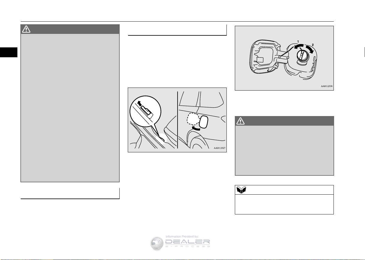
Refueling
1. Before filling with fuel, stop the engine.
2. The fuel tank filler is located on the rear
driver side of your vehicle.
The fuel tank filler door can be opened
from inside the vehicle with the fuel tank
filler door release lever located at the left
side of the driver’s seat.
3. Open the fuel tank filler pipe by slowly
turning the fuel tank filler cap counterclockwise.
1- Remove
2- Close
Since the fuel system may be under pres-
sure, remove the fuel tank filler cap
slowly. This relieves any pressure or vacuum that might have built up in the fuel
tank. If the cap is venting vapor or if you
hear a hissing sound, wait until the sound
stops before removing the cap. Otherwise,
fuel may spray out, injuring you or others.
Fuel tank capacity
All-wheel drive vehicles: 15.8 gal (60 L)
Front-wheel drive vehicles: 16.6 gal (63 L)
3-4 General information
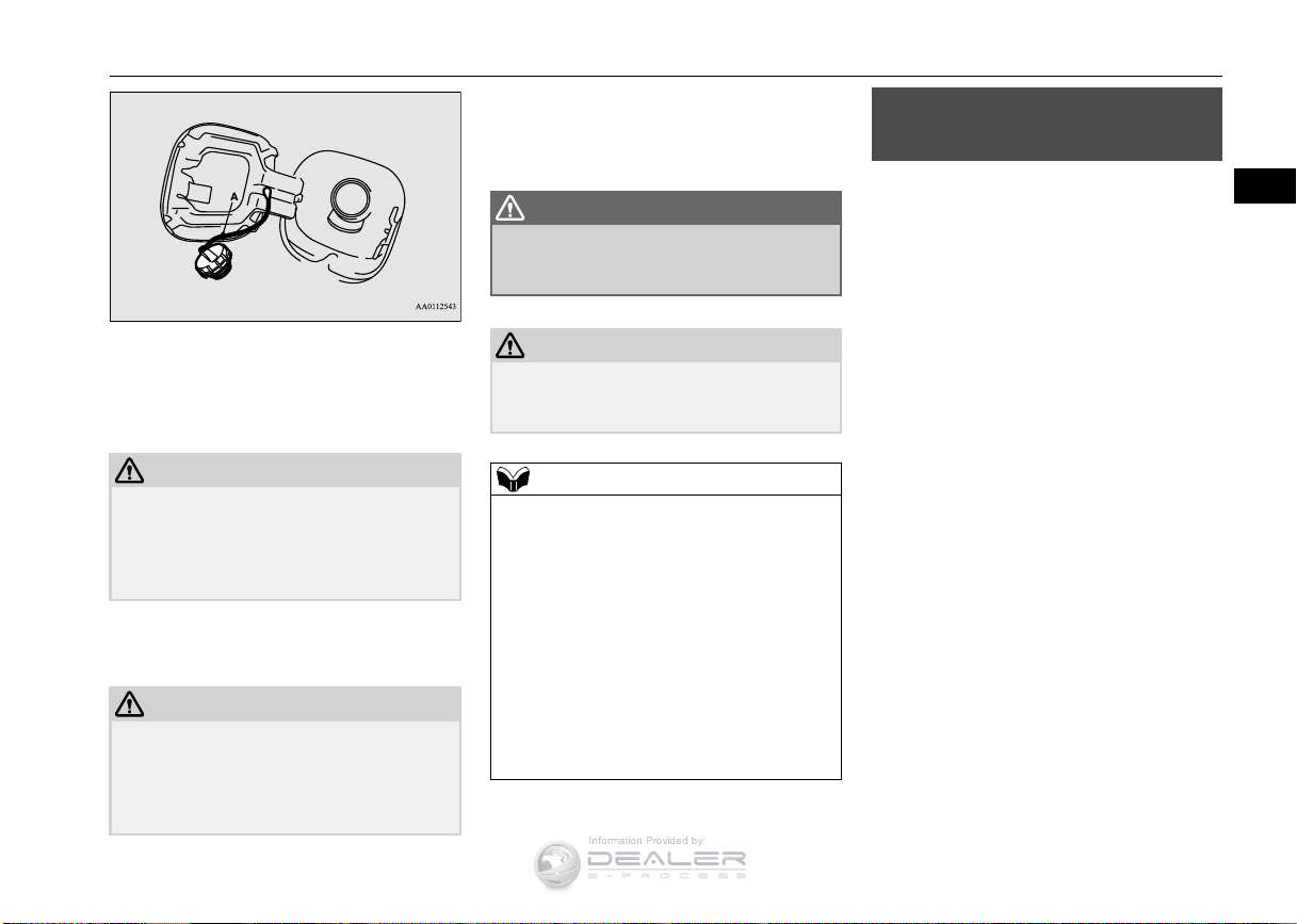
While filling with fuel, hang the fuel cap on
the hook (A) located on the inside surface of
the fuel tank filler door.
Page 24
3
CAUTION
CAUTION
WARNING
CAUTION
NOTE
Information Provided by:
4. Fueling correctly depends mainly on correct handling of the fuel filler nozzle. Do
not tilt the nozzle. Insert the nozzle in the
fuel tank filler port as far as it goes.
Your vehicle can only be operated using
unleaded gasoline. Serious engine and catalytic converter damage will result if leaded
gasoline is filled into these vehicles, and
consequently, this must never be attempted.
5. When the nozzle stops automatically, do
not add more fuel.
To avoid fuel spillage and overfilling, do not
“top-off” the fuel tank. Spilled fuel could
discolor, stain, or crack the vehicle’s paintwork. If fuel spills on the paintwork, wipe it
off with a soft cloth.
6. To re-install, turn the fuel tank filler pipe
cap slowly clockwise until you hear clicking sounds, then gently push the fuel tank
filler door closed.
Make sure the fuel tank filler cap is
securely closed. If the fuel cap were loose,
fuel could leak, resulting in a fire.
If you need to replace the fuel tank filler cap,
use only the cap specified for your model
vehicle.
If the fuel tank filler cap is not tight while
driving, the engine malfunction indicator
(“SERVICE ENGINE SOON” or “Check
engine light”) may come on when the
onboard diagnostic (OBD) system performs
a self check.
Always tighten the fuel tank filler cap until
you hear at least 3 clicks.
The indicator will go off after several driving
cycles. If the indicator does not go off, contact your authorized Mitsubishi Motors
dealer or a repair facility of your choice as
soon as possible.
Modifications to and racing of your vehicle
Modifications to and racing
of your vehicle
N00301600152
This vehicle should not be modified with
non-Mitsubishi Motors genuine parts. Mitsubishi Motors designs and manufactures
high quality vehicles with an emphasis on
safety and durability. Modifications using
non-Mitsubishi Motors genuine parts may
affect the performance, safety and/or durability of your vehicle, and may violate applicable state and/or federal regulations.
DAMAGE OR PERFORMANCE PROBLEMS RESULTING FROM MODIFICATIONS TO OR RACING OF YOUR
VEHICLE ARE NOT COVERED UNDER
WA R R AN T Y.
Examples of modifications to your vehicle
that can cause damage or performance problems include the following:
Failure to use Mitsubishi Motors genuine
parts
Failure to use required fuel and fluids
Failure to use proper size tires and wheels
Modification of the fuel, intake, exhaust,
emission, suspension, engine, drive train
or electrical wiring systems
General information 3-5
Page 25
Genuine Mitsubishi Motors parts
3
CAUTION
WARNING
CAUTION
Information Provided by:
Modification of any onboard com-
puter/control module, including reprogramming, or replacing/adding chips to
any onboard computer/control module
Review the Warranty and Maintenance Manual for further details regarding warranty coverage.
Installation of accessories
Before any electrical or electronic accesso-
ries are installed, consult an authorized Mitsubishi Motors dealer.
The installation of accessories, optional
parts, etc., should only be performed
within the limits prescribed by law, and in
accordance with the guidelines and warnings contained within the documents
accompanying this vehicle.
Only Mitsubishi Motors approved accessories should be fitted to your vehicle.
Improper installation of electrical parts
could cause a fire. Refer to the “Modification/alterations to the electrical or fuel
systems” section within this owner’s manual.
N00301701219
Using a cellular phone or radio set inside
the vehicle without an external antenna
may cause electrical system interference,
which could lead to unsafe vehicle operation.
Tires and wheels which do not meet spec-
ifications must not be used.
Refer to the “Specifications” section for
information regarding wheel and tire
sizes.
While driving, do not use a cellular phone
in a way that hinders safe driving. Anything, including cellular phone usage, that
distracts you from the safe operation of
your vehicle increases your risk of an accident.
Refer to and follow all state and local laws
in your area regarding cellular phone
usage while driving.
Important point!
Due to the large number of accessory and
replacement parts provided by different manufacturers in the market, it is not always possible for an authorized Mitsubishi Motors
dealer to check whether the attachment or
installation of a non-Mitsubishi Motors genu-
ine parts affects the driving safety of your
Mitsubishi-vehicle.
Modification/alterations to the
electrical or fuel systems
N00301800141
Mitsubishi Motors manufactures high quality
vehicles with an emphasis on safety. It is
important to consult an authorized Mitsubishi
Motors dealer before installation of any
accessory which may involve modification of
the electrical or fuel systems.
Please consult an authorized Mitsubishi
Motors dealer concerning any such accessory fitment or modification.
If the wires interfere with the vehicle body or
improper installation methods are used (protective fuses not included, etc.), electronic
devices may be adversely affected, resulting
in a fire, vehicle damage, or other accident.
Genuine Mitsubishi Motors
parts
N00301400219
Mitsubishi Motors Genuine Parts are
designed and manufactured to meet high standards of performance, and are recommended
for all of your maintenance needs. Also avail-
3-6 General information
Page 26
California Perchlorate Materials Requirements
3
Information Provided by:
able from your Mitsubishi Motors dealer are
a wide variety of accessories to personalize
your new vehicle. Each Mitsubishi Motors
vehicle has a selection of Mitsubishi Motors
authorized accessories to choose from to tailor your new vehicle to your own personal
preference. Your Mitsubishi Motors dealer’s
Parts Manager has information on various
audio systems, protection items, as well as
interior and exterior accessories available for
your specific model.
California Perchlorate
Materials Requirements
N00300100017
Certain components of this vehicle, such as
airbag modules, seat belt pretensioners, and
button cell batteries, may contain perchlorate
materials.
Special handling may apply. For additional
information, see www.dtsc.ca.gov/hazardouswaste/perchlorate.
General information 3-7
Page 27

Information Provided by:
Page 28
4
Seat and restraint systems
Information Provided by:
Seats .................................................................................................4-2
Seat arrangement .............................................................................4-3
Seats and restraint systems ..............................................................4-4
Front seats ........................................................................................4-4
Second row seats ..............................................................................4-8
Third row seat (Seating 7 passengers) ...........................................4-10
Head restraints ...............................................................................4-10
Making a cargo area .......................................................................4-12
Making a flat seat ...........................................................................4-16
Seat belts ........................................................................................4-17
Seat belt use during pregnancy ......................................................4-24
Seat belt pre-tensioner and force limiter systems ..........................4-24
Child restraint systems ...................................................................4-25
Maintenance and inspection of seat belts ......................................4-32
Supplemental Restraint System (SRS) - airbag .............................4-33
Page 29
4
Information Provided by:
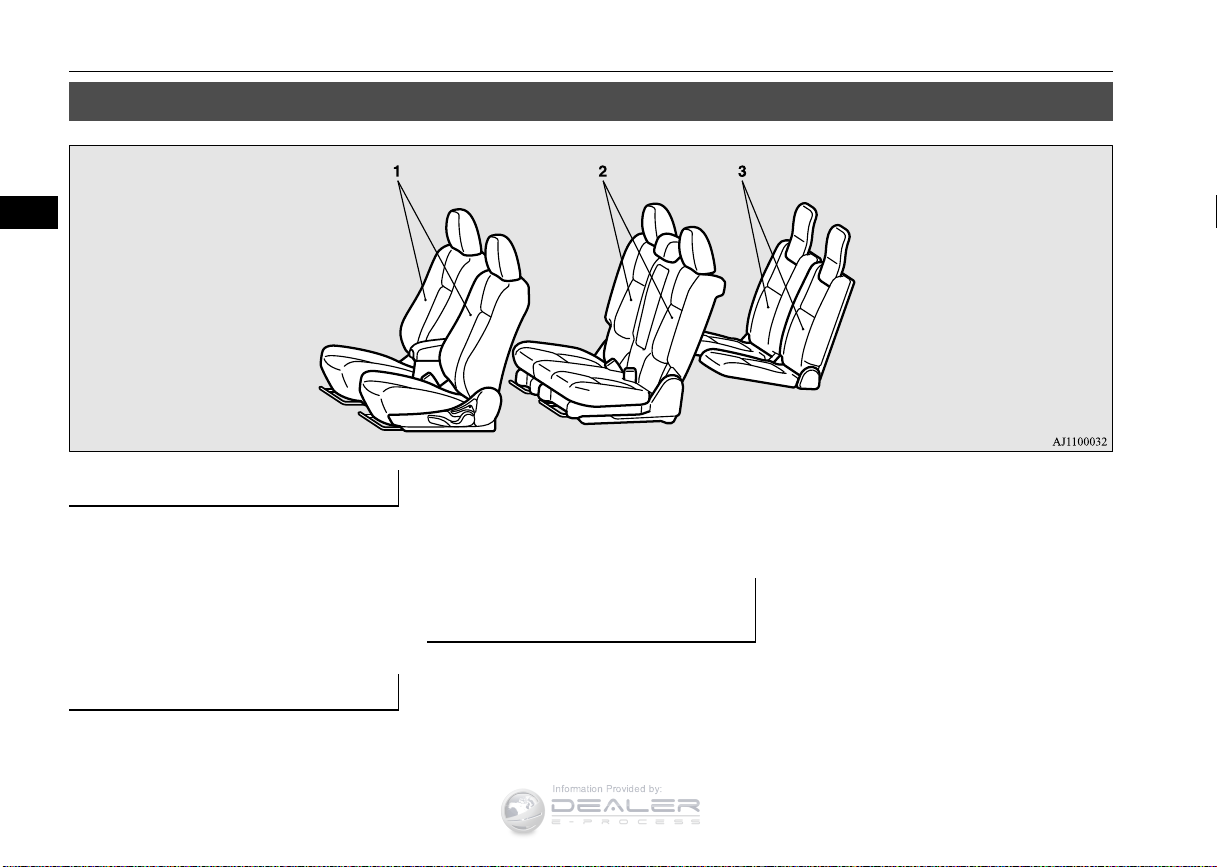
Seats
Seats
N00408401519
1 - Front seat
To adjust the seat forward or back-
wardPage 4-5
To adjust the seatback Page 4-6
To adjust the seat height (Driver’s seat
only) Page 4-6
Heated seat (if so equipped) Page 4-7
2 - Second row seats
To adjust the seat forward or backward
(vehicles with second row seat slide function) Page 4-8
4-2 Seat and restraint systems
To adjust the seatback Page 4-8
Arm rest Page 4-9
Accessing the third row seat (Seating 7
passengers) Page 4-9
3 - Third row seat (Seating 7
passengers)
To adjust the seatback Page 4-10
Page 30
Seat arrangement
4
Information Provided by:
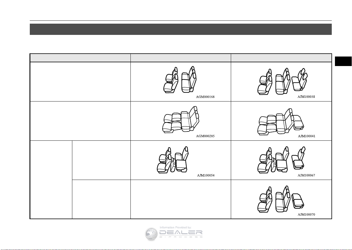
Seat arrangement
N00401701122
You may arrange your seats in the following positions.
Seating 5 passengers Seating 7 passengers
Ordinary use
Flat seatPage 4-16
Folding the second row
seats
Page 4-13
Making a cargo
area
Folding the third row
seatsPage 4-15
—
Seat and restraint systems 4-3
Page 31

Seats and restraint systems
4
WARNING
Manual seat adjustment Power seat adjustment
CAUTION
WARNING
Information Provided by:
Seats and restraint systems Front seats
Your vehicle has seat belts and other safety
features that help protect you and your passengers in an accident.
Seat belts are the most important safety
device. When worn properly, seat belts can
reduce the chance of serious injury or death
in various types of crashes. For added protection during a severe frontal collision, your
vehicle has a Supplemental Restraint System
(SRS) with airbags for the driver and passengers. The seats, head restraints, and door
locks also are safety equipment, which must
be used correctly.
Always check the following before you drive:
That everyone in your vehicle is properly
wearing their seat belt.
That infants and small children are prop-
erly secured in an appropriate child
restraint system in the rear seat.
That all doors are fully closed and locked.
That seatbacks are upright, with head
restraints properly adjusted.
Safety equipment cannot prevent injury or
death in all motor vehicle accidents. However, you can help reduce the risk of injury or
death, by following the instructions in this
manual.
N00401601219
N00401801426
Position the driver’s seat as far back as possible while maintaining a position that still
enables you to fully apply the pedals, easily
control the steering wheel and safely operate
the vehicle.
Do not attempt to adjust the seat while
driving. This can cause loss of vehicle control and result in an accident.
After adjusting the seat, make sure that it
is securely locked into position.
To reduce the risk to the driver of serious
injury or death during deployment of the
driver’s airbag, always properly wear the
seat belt and adjust the driver’s seat as far
back as possible while maintaining a position that still enables you to fully apply the
pedals, easily control the steering wheel,
and safely operate the vehicle.
To reduce the risk to the front passenger
of serious injury or death during deployment of the passenger’s airbag, always
properly wear the seat belt and adjust the
front passenger’s seat as far back as possible.
Always place children 12 years old and
under in the rear seat and use appropriate
child restraint systems.
Make sure that the seat is adjusted by an
adult. If it is adjusted by a child, an unexpected accident might occur.
Do not place a cushion or the like between
your back and the seatback while driving.
The effectiveness of the head restraints will
be reduced in the event of an accident.
When sliding the seats, be careful not to
catch your hand or leg.
When sliding or reclining the seat rearward,
pay careful attention to the second row seat
passengers.
4-4 Seat and restraint systems
Page 32

Front seats
4
CAUTION
WARNING
NOTE
Information Provided by:
To adjust the seat forward or
When adjusting the front seat while the sec-
ond row seat is folded, be careful not to
apply strong force to the flipped second row
seat cushion.
Doing so could cause damage to the cover of
the front seat and the fitting of the second
row seat cushion.
backward
N00401901326
Manual seat adjustment
Pull the seat adjusting lever up and slide the
seat forward or backward to the desired position. Release the adjusting lever to lock the
seat in place.
To make sure that the seat is securely
locked, try to move it forward or backward without using the adjusting lever.
Power seat adjustment
Operate the switch forward or backward to
move the seat to the desired position. Release
the switch to lock the seat in place.
1- Forward (toward the front of the vehicle)
2- Backward (toward the rear of the vehi-
cle)
To prevent the battery from completely dis-
charging, operate the power seat with the
engine running.
Seat and restraint systems 4-5
Page 33

Front seats
4
CAUTION
NOTE
WARNING
Information Provided by:
To adjust the seatbacks
Manual seat adjustment
To adjust the seatback, lean forward slightly,
gently pull the seatback lock lever up, then
lean backward to a comfortable position and
release the lever. The seatback will lock in
place.
The reclining mechanism used in the seat-
back is spring loaded, and will cause the
seatback to return quickly to the vertical
position when the lock lever is operated.
When pulling the lever, sit close to the seatback or hold the seatback with your hand to
control its return motion.
N00402001379
Power seat adjustment
Operate the switch in the direction of the
arrows to adjust the seatback.
1- Move forward
2- Move backward
To prevent the battery from completely dis-
charging, operate the power seat with the
engine running.
To reduce the risk of serious injury or
death in the event of an accident or sudden stop, all seatbacks should be kept in
the upright position while the vehicle is in
motion.
Seat belt performance during an accident
can be adversely affected if the seatbacks
are reclined. The more a seatback is
reclined, the more likely seat belt performance will be adversely affected. If the
seat belt is not properly positioned against
the body during an accident, there is
increased risk you will slide under the belt
and receive serious injury or death.
To adjust the seat height
(Driver’s seat only)
N00402101253
Manual seat adjustment
Operate the lever repeatedly to raise or lower
the seat.
4-6 Seat and restraint systems
Page 34

Front seats
4
NOTE
Information Provided by:
1- Raise
2- Lower
Power seat adjustment
Operate the switch in the direction of the
arrows to raise or lower the seat.
To prevent the battery from completely dis-
charging, operate the power seat with the
engine running.
1- Raise or lower the front end of the seat
2- Raise or lower the back end of the seat
3- Raise or lower the entire seat
Heated seat (if so equipped)
N00435601391
The heated seats can be operated by pushing
the switch when the ignition switch or the
Seat and restraint systems 4-7
Page 35

Second row seats
4
WARNING
CAUTION
NOTE
Information Provided by:
operation mode is in ON. The indicator light
(A) will illuminate while the heater is on.
1 (HI) - Heater high (for quick heating)
2 - Heater off
3 (LO) - Heater low (to keep the seat warm)
Persons who are unable to feel tempera-
ture change or skin pain due to age, illness, injury, medication, alcohol use,
fatigue or other physical conditions or
who have sensitive skin may suffer burns
when using the heated seat even at low
temperatures. To reduce the risk of burns,
people with such conditions must use care
when using the heated seat.
Switch off the heated seats when not in use.
Operate the heaters at the “HI” position for
quick heating. After the seat has become
warm, set the heater switch to the “LO” position to keep it warm. Slight variations in the
seat temperature may be felt while using the
heated seats. This is caused by the operation
of the heater’s internal thermostat and does
not indicate a malfunction.
Do not place heavy objects on the seat or
stick pins, needles, or other pointed objects
into the seat.
Do not place a blanket, cushion, or other
insulating material on the seat while using
the heater; doing so can cause the heater element to overheat.
When cleaning the seat, do not use benzine,
kerosene, gasoline, alcohol, or other organic
solvents; doing so can cause damage not
only to the surface of the seat, but also to the
heater.
If water or any other liquid is spilled on the
seat, allow it to dry thoroughly before
attempting to use the heater. Turn the heater
off immediately if it appears to be malfunctioning during use.
Second row seats
N00402501231
When sitting in the middle seating position of
the second row seat, adjust the head restraints
to an appropriate height where they lock in
position. Refer to “Head restraints” on page
4-10.
To adjust the seat forward or
backward (vehicles with second row seat slide function)
Pull the seat adjusting lever up and slide the
seat forward or backward to the desired position. Release the adjusting lever to lock the
seat in place.
You can adjust the seat forward or backward
on either side separately.
4-8 Seat and restraint systems
Page 36

4
WARNING
CAUTION
NOTE
WARNING
NOTE
Information Provided by:
To make sure that the seat is securely
locked, try to move it forward or backward without using the adjusting lever.
When sliding (vehicles with second row seat
slide function) or reclining the seat rearward,
pay careful attention to the third row seat
passengers.
To adjust the seatbacks
Pull the lever up and adjust the seatback by
hand to the desired position, and release the
lever. The seatback will lock in place.
You can adjust the seatback forward or back-
ward on either side separately.
To reduce the risk of serious injury or
death in the event of an accident or sudden stop, all seatbacks should be kept in
the upright position while the vehicle is in
motion.
Seat belt performance during an accident
can be adversely affected if the seatbacks
are reclined. The more a seatback is
reclined, the more likely seat belt performance will be adversely affected. If the
seat belt is not properly positioned against
the body during an accident, there is
increased risk you will slide under the belt
and receive serious injury or death.
When a person is sitting in the middle
seating position of the second row seats,
the two sides of the second seats must have
the same forward/backward position
(vehicles with second row seat slide function) and the same seatback angle.
Second row seats
Arm rest
N00403001318
To use the armrest, tilt the arm rest down for
use as shown.
The arm rest includes a cup holder.
Never sit on an arm rest.
Doing so could damage the arm rest.
Accessing the third row seat
(Walk-in function, Seating 7
passengers)
N00400101031
For third row seat passenger entry or exit, the
second row seats can be moved forward.
Pull up the lever (A) and tilt the seatback forward. Then slide the entire seat forward.
Seat and restraint systems 4-9
Page 37

Third row seat (Seating 7 passengers)
4
WARNING
WARNING
Information Provided by:
To return the seat, slide the entire seat backward to the desired position and then raise the
seatback until it locks securely.
After returning the seat, gently try to move it
forward and backward to check that it is
securely retained and adjust the seatback to
the normal seating position.
To make sure that the seat is securely
locked, try to move it forward or backward without using the lever. To reduce
the risk of serious injury or death in the
event of an accident or sudden stop, all
seatbacks should be kept in the upright
position while the vehicle is in motion.
Third row seat (Seating 7
passengers)
N00419501073
The third row seats are intended for use
by no more than two belted occupants,
each of which does not exceed 160 cm (63
inches) in height.
Exceeding these limitations can result in
an increased risk of personal injury or
death in the event of an accident.
To adjust the seatback
Pull up the strap and adjust the seatback by
hand to the desired position, and release the
strap.
Head restraints
N00404301594
Head restraints can reduce the risk of a whiplash injury if your vehicle is hit from the rear.
The head restraints are equipped in the illustrated position.
To maximize the effectiveness of the head
restraints, adjust the seatback to the upright
position, and the head restraint to the proper
position. Sit back against the seatback with
your head close to the head restraint.
*: Seating 7 passengers
4-10 Seat and restraint systems
Page 38

Head restraints
4
WARNING
NOTE
WARNING
Information Provided by:
Adjustment of the head
Driving without the head restraints in
place can cause you and your passengers
serious injury or death in an accident. To
reduce the risk of injury in an accident,
always make sure the head restraints are
installed and properly positioned when
the seat is occupied.
In order to minimize the risk of a neck
injury due to a rear impact, the seatback
must be adjusted to the upright position
and the head restraint must be adjusted to
the proper position before vehicle operation. The driver should never adjust the
seat while the vehicle is in motion.
Never place a cushion or similar device on
the seatback. This can adversely affect
head restraint performance by increasing
the distance between your head and the
restraint.
When a person sits in the second center
seating position, pull up the head restraint
to a height at which it locks in position. Be
sure to make this adjustment before starting to drive. Serious injuries could otherwise be suffered in the result of an impact.
The head restraint height in the second row
outboard seats and the third row seats cannot
be adjusted.
restraint height (front seats)
To reduce the risk of injury in an accident,
adjust the head restraint height so that the
center of the restraint is at your ear level
when seated. Any person too tall for the
restraint to reach their ear level when seated
should raise the restraint to the highest locked
position.
To raise the restraint, pull it straight up.
To lower the restraint, push down on it
while pressing the lock knob (A) in the
direction shown by the arrow.
After adjusting the height, push down on
the restraint to make sure it is locked in
position.
Seat and restraint systems 4-11
Page 39

Making a cargo area
4
WARNING
CAUTION
CAUTION
WARNING
Information Provided by:
To remove
Press the lock knob (A) in the direction
shown by the arrows. Then pull the head
restraint up and out of the seatback.
To help minimize the risk of neck injury in
the event of an accident, the head
restraints must be properly installed and
positioned to proper height before vehicle
operation.
To install
First check that the head restraint is facing in
the right direction as shown in the previous
illustration, and then insert it into the seatback. Push the head restraint down while
pressing the lock knob (A) until the restraint
locks into place.
Check that the lock knob (A) is extended out
as shown in the illustration. Then pull the
head restraint up to make sure that it is
locked in place and will not come out of the
seatback.
The shape and size of the head restraint dif-
fers according to the seat. Always use the
correct head restraint provided for the seat
and do not install the head restraint in the
wrong direction.
Making a cargo area
N00405501115
Never adjust the seats to make a cargo
area when the vehicle is in motion or on a
slope. The seats could move more than
necessary or move suddenly and causing a
serious accident and/or injury.
When returning a seat back to its seating
position after folding down, make sure
that the seat is firmly secured and seat belt
buckles are in proper position. If the seat
is not secured, it could move causing a
serious accident.
Do not allow anyone to ride in the cargo
area while the vehicle is in motion. People
who are not properly seated and
restrained can be seriously injured or
killed in an accident.
4-12 Seat and restraint systems
Page 40

Making a cargo area
4
CAUTION
NOTE
WARNING
NOTE
NOTE
Information Provided by:
When driving the vehicle, do not allow
anyone to sit on the third row seat if the
second row seat is in the folded position.
In the cargo area, do not load the luggage
higher than the top of the seats and make
sure that the luggage is firmly secured.
Restricted rear vision or flying objects entering the passenger compartment during sudden braking could result in a serious accident
and/or injury.
Seats should always be operated by an adult.
Seat adjustments by a child could lead to an
unexpected accident.
When adjusting the seats, be careful not to
catch your hand or leg. Personal injury could
result.
When the seatback of a front seat is reclined,
return it to the upright position before driving.
Folding the second row seats
The second row seat can be folded to create
an additional cargo area.
N00405701120
You can separately fold the right and left side
of the second row seat.
To fold the second row seat
1. Remove the head restraints from the second row outside seating position.
Lower the head restraint for second row
middle seating position to its lowest position.
Refer to “Head restraints” on page 4-10.
2. When the left side second row seat is
folded, store the seat belt for the middle
seating position of the second row seat.
Refer to “Detachable center seat belt for
second row” on page 4-20.
3. On vehicles with the second row seat slide
function, move the second row seat fully
backward.
Refer to “To adjust the seat forward or
backward” on page 4-8.
If you do not move the second row seat fully
backward, you may not be able to fold the
second row seat.
4. Lift the front end of the seat cushion.
5. Flip the seat cushion forward. On vehicles
with the third row seats, move the lever
(A) to the luggage area mode position.
6. Fold forward the seat belt buckle.
Seat and restraint systems 4-13
Page 41

Making a cargo area
4
CAUTION
CAUTION
NOTE
Information Provided by:
Do not allow any person to get on the plastic
cover (B), and do not place luggage on it.
Doing so could damage the plastic cover.
7. Pull up the lever (C), then fold the seatback forward.
Do not allow any person to sit on the flipped
seat cushion, and do not place luggage on it.
The seat’s mounting fittings could bend
under the weight, making it impossible for
the seat cushion to be secured when it returns
to the original position.
When folding the second row seatback for-
ward once, the seat will automatically switch
from the luggage area mode to the walk-in
mode.
8. Put the head restraint on the hook (D)
with their front faces facing upward until
it locks into place.
To retur n
1. Remove the head restraint from the hook.
2. Raise the seatback until it locks securely
into place.
3. On vehicles with the third row seats,
make sure that the lever is in the walk-in
mode position.
Otherwise, move the lever to the walk-in
mode position.
4. While lifting the seat belt buckle (A), gently lower the seat cushion. Make sure that
there is a hook (B) at the position shown
in the illustration.
4-14 Seat and restraint systems
Page 42

Making a cargo area
4
NOTE
Information Provided by:
A rubber strap (C) is attached to the seat belt
buckle for the left outboard seating position.
This helps raise the seat belt buckle while the
seat cushion returns to the original position.
5. Push down the seat cushion until it locks
into place.
6. Make sure that all seat belt buckles are
properly positioned on the seat cushion.
Install the head restraints and make sure
that they are securely locked.
7. If the center seat belt is stored;
• Pull out the detachable anchor plate (D)
from the seatback.
• Pull the small latch plate (E) slowly and
insert it into the detachable anchor plate
until a click is heard.
• Make sure that the seat belt is not
twisted.
For details, refer to “Datachable center
seat belt for second row” on 4-20.
Folding the third row seats
(Seating 7 passengers)
N00409800021
To fold
1. Remove the head restraints from the third
row seats. (Refer to “Head restraints” on
page 4-10.)
2. Pull up the strap (A), then fold the seatback forward.
Seat and restraint systems 4-15
Page 43

Making a flat seat
4
WARNING
CAUTION
CAUTION
Information Provided by:
3. Stow the removed head restraints in the
luggage floor box with their front faces
facing downward.
To retur n
2. Install the head restraints.
Making a flat seat
N00404801166
The entire interior of the vehicle may be used
for sleeping accommodations by removing
the head restraints and fully reclining all the
seats when the vehicle is stopped.
Never drive with passengers or cargo on
the flat seat. This is extremely dangerous
and can cause severe or fatal injury or
death in an accident or if heavy braking is
required.
Seat should be adjusted only by adults to
avoid accidents.
When sliding the seats, be careful not to
catch your hand or leg.
Do not walk around on top of the seats after
they have been laid flat because the footing
is uneven. It is safest to move about on your
hands and knees.
To ensure the seats are locked securely,
attempt to move them back and forth.
Do not jump on or drop heavy objects on the
seatbacks.
To raise the seatback of the front seat, firmly
place your hand on the seatback, pull the
seatback lock knob up, and raise the seatback
slowly. (Refer to “To adjust the seatback” on
page 4-6.) Do not let children adjust the seatback.
1. Remove the head restraints from the front
seats and raise the arm rest on the second
row seats.
For vehicles with a cargo area cover,
remove the cover.
(Refer to “Head restraints” on page 4-10,
“Arm rest” on page 4-9 and “Cargo area
cover” on page 5-218.)
1. Pull the strap (A), then raise the seatback
until it locks securely into place.
Push lightly on the seatback to confirm
that it has actually been secured.
4-16 Seat and restraint systems
Adjust the seats only when the vehicle is
stopped in a safe place.
Page 44

4
(Refer to “To adjust the seat forward or
WARNING
Information Provided by:
backward” on page 4-5 and “To adjust the
seatback” on page 4-6.)
Seat belts
To return the seats to the normal position,
reverse the above procedure.
2. Slide the second row seats back as far as
possible (vehicles with second row seat
slide function).
(Refer to “To adjust the seat forward or
backward” on page 4-8.)
3. Slide the front seats fully forward, then
recline their seatbacks backward to
achieve a flat surface.
4. Recline the seatbacks of the second row
seats.
(Refer to “To adjust the seatback” on page
4-8.)
5. The flat seat configuration is now complete.
Seat belts
N00406001481
Seat belts are installed in your vehicle to help
reduce the risk of injury to the driver and passenger in the event of an accident. Always
use the provided seat belts.
Carefully review the following information
for proper seat belt usage.
To help reduce the risk of injury or death
in an accident, seat belts and child
restraint systems must always be used.
Refer to “Child restraint systems” on page
4-25 for additional information.
Never use one seat belt for more than one
person.
Seat and restraint systems 4-17
Page 45

Seat belts
4
WARNING
WARNING
NOTE
Information Provided by:
Never carry more people in your vehicle
than there are seat belts.
Always adjust the seat belt for a snug fit.
Always place the shoulder belt over your
shoulder and across your chest. Never put
it behind you or under your arm.
Always wear the lap belt as low as possible
across your hips, not around your waist.
Never modify or alter the seat belts in
your vehicle.
To reduce the risk to the driver of serious
injury or death during deployment of the
driver’s airbag, always properly wear the
seat belt and adjust the driver’s seat as far
back as possible while maintaining a position that still enables you to fully apply the
pedals, easily control the steering wheel,
and safely operate the vehicle.
To reduce the risk to a front seat passen-
ger of serious injury or death from a
deploying airbag, make sure the passenger
always wears the seat belt properly,
remains seated all the way back and
upright in their seat, and moves the seat as
far back as possible. Refer to “Supplemental Restraint System (SRS) - airbag” on
page 4-33 for additional information.
Never hold an infant or child in your arms
or on your lap when riding in this vehicle
even when you are wearing your seat belt.
Never place any part of the seat belt you
are wearing around an infant or child.
Failure to follow these simple instructions
creates a risk of serious injury or death to
your child in the event of an accident or
sudden stop.
Children 12 years old and under should
always ride in the rear seat and be properly restrained. This reduces their risk of
serious injury or death in an accident,
especially due to a deploying front passenger’s airbag. Refer to “Child restraint systems” on page 4-25 for additional
information.
Any child who is too small to properly
wear a seat belt must be properly
restrained in an appropriate child
restraint system.
Infants MUST be placed in a rear-facing
child safety seat and positioned in the rear
seat.
In the event of an accident, all seat belt
assemblies, including retractors and
attachment hardware, should be inspected
by an authorized Mitsubishi Motors
dealer to determine whether replacement
is necessary.
Seat belt instructions
N00406201467
All seats are equipped with a seat belt which
uses one combined lap-and-shoulder belt with
an emergency locking retractor.
This system is designed to provide both comfort and safety. It permits full extension and
automatic retraction of the belts during normal vehicle operation. A sensing device
inside the belt retractor is designed to lock the
retractor in the event of a sudden change in
the vehicle’s motion.
For instructions on installing a child restraint
system using a seat belt, refer to “Installing a
child restraint system using the seat belt” on
page 4-30.
4-18 Seat and restraint systems
Page 46

Seat belts
4
WARNING
NOTE
Information Provided by:
1. Occupants should always sit back in their
seats with their backs against the upright
seatback. To reduce the risk of serious
injury or death during deployment of the
airbag, adjust the driver’s seat as far back
as possible while maintaining a position
To reduce the risk of serious injury or
death in the event of an accident or sudden stop, all seatbacks should be kept in
the upright position while the vehicle is in
motion.
that still enables you to fully apply the
pedals, easily control the steering wheel,
and safely operate the vehicle. The front
passenger seat should also be moved as
far back as possible. Refer to “Supplemental Restraint System (SRS) - airbag”
on page 4-33. Also refer to “To adjust the
seat forward or backward” on page 4-5.
Seat belt performance during an accident
can be adversely affected if the seatbacks
are reclined. The more a seatback is
reclined, the more likely seat belt performance will be adversely affected. If the
seat belt is not properly positioned against
the body during an accident, there is
increased risk you will slide under the belt
and receive serious injury or death.
2. Grasp the latch plate and slide it up the
webbing so that it easily pulls across your
body.
3. Pull the seat belt out slowly while holding
the latch plate. Push the latch plate into
the buckle until you hear a “click”. Pull
up on the belt to be sure the latch plate is
locked securely in the buckle.
If the seat belt locks up and cannot be pulled
out, pull it once with force and let it retract
all the way.
Then, pull the belt out slowly once again.
4. The lap part of the belt must always be
worn low and snug across the hips. Pull
up on the shoulder portion of the belt to
take up any slack in the lap belt.
Seat and restraint systems 4-19
Page 47

Seat belts
4
NOTE
WARNING
WARNING
WARNING
NOTE
Information Provided by:
With the exception of the seat belt for the
driver, the seat belts in all other seating positions are equipped with an Automatic Locking Retractor (ALR) function. If you pull the
seat belt fully out of the retractor, the retractor will switch to its ALR child restraint
installation function (see page 4-30).
When the ALR function has been activated,
the seat belt will only retract. If this happens,
let the belt fully retract, then pull the seat
belt back out, repeating steps 1 through 4.
Be sure the lap belt portion fits snugly and
is worn as low as possible across the hips,
not around the waist. Failure to follow this
instruction will increase the risk of serious
injury or death in the event of an accident.
Be sure the seat belt webbing is not
twisted when worn. Twisted webbing may
adversely affect seat belt performance.
5. To release the belt, press the button on the
buckle and allow the belt to retract.
If the belt does not retract smoothly, pull it
out and check for kinks or twists in the
webbing. Then make sure it remains
untwisted as it retracts.
Detachable center seat belt for
second row
N00409900022
The center seat belt for the second row can be
detached to fold the left side second row seat.
This seat belt must be worn correctly as illustrated.
Never detach the center seat belt except
when the left side seat back in the second
row is folded. Using the center seat belt
with the detachable anchor unlatched
increases the risk of serious injury or
death in an accident. Make sure the small
latch plate (A) is properly latched to the
detachable anchor before the center seat
belt is used.
To attach
1. Pull out the detachable anchor plate (C)
from the storage pocket on seat back
cushion.
2. Pull the small latch plate (A) slowly and
insert it into the detachable anchor plate
until a click is heard. Make sure that the
seat belt is not twisted.
If the seat belt locks up and cannot be pulled
out, pull it once with force and let it retract
all the way.
Then, pull the belt out slowly once again.
The seat belt can be buckled up by inserting
the latch plate (B) into the buckle (D) like
other seat belts.
4-20 Seat and restraint systems
Page 48

4
If the seat belt switch to the ALR child
NOTE
NOTE
Information Provided by:
restraint installation function and cannot be
pulled out, detach the latch plate (B) and
move the second row seat fully backward.
Refer to “Installing a child restraint system
using the seat belt” on page 4-30.
Seat belts
To deta ch
1. While holding the seat belt, insert a metal
plate, such the latch plate of the seat belt
or a key, into the slit (E) on the detachable
anchor (C) and release the center seat belt
from the detachable anchor.
2. Retract the seat belt slowly by holding the
seat belt.
If the seat belt is not held, the seat belt will
rapidly retract. This could cause damage to
the interior trim.
3. After the seat belt has retracted completely, insert the latch plate (B) into the
upper slit (F), and then insert the small
latch plate (A) into the lower slit (G).
4. Store the detachable anchor in the storage
pocket on the seatback.
Seat and restraint systems 4-21
Page 49

Seat belts
4
Type 1
Type 2
WARNING
NOTE
Information Provided by:
Driver’s seat belt
reminder/warning light and
display
N00418401394
warning light will come on and a tone will
sound for approximately 6 seconds to remind
you to fasten your seat belt.
If the vehicle is driven with the seat belt still
unfastened, the warning light will blink and
the tone will sound intermittently until the
seat belt is fastened. At the same time, “FASTEN SEAT BELT” is displayed on the information screen in the multi information
display (Type 1 only).
In order to reduce the risk of serious
injury or death in an accident, always fasten your own seat belt. Do not allow anyone to ride in your vehicle unless he or she
is also seated and fastening a seat belt.
Children should additionally be restrained
in a secure child restraint system.
If the seat belt subsequently remains unfas-
tened, the warning light and the tone will
issue further warnings each time the vehicle
starts moving from a stop.
Front passenger seat belt warning light
N00418301247
The front passenger seat belt warning light is
located in the instrument panel.
When the ignition switch is turned to the
“ON” position or the operation mode is put in
ON, this indicator normally comes on and
goes off a few seconds later.
The light comes on when a person sits on the
front passenger seat but does not fasten the
seat belt. It goes off when the seat belt is subsequently fastened.
A tone and warning light are used to remind
the driver to fasten the seat belt.
If the ignition switch is turned to the “ON”
position or the operation mode is put in ON
without the driver’s seat belt being fastened, a
4-22 Seat and restraint systems
Page 50

Seat belts
4
WARNING
Anchor down Anchor up
WARNING
Information Provided by:
Storing the second row (out-
When a child booster seat is used on the
front passenger seat, the front passenger
seat belt warning light will not come on, if
the seat belt is not fastened when the
booster seat is used. Confirm that the
child is wearing the seat belt properly.
Do not install any accessory or sticker that
makes the light difficult to see.
Adjustable seat belt shoulder
anchor (front seats)
N00406301354
The seat belt shoulder anchor height can be
adjusted. To move the anchor down, press the
lock knob (A) and slide the anchor down to
the desired position. To move the anchor up,
slide the anchor up to the desired position.
Always adjust the shoulder belt anchor so
that the shoulder belt is positioned across
the center of your shoulder without touching your neck. The shoulder belt should
not be able to fall off your shoulder. Failure to follow this instruction can adversely
affect seat belt performance and increase
the risk of serious injury or death in the
event of an accident.
Adjust the shoulder belt anchor only when
the vehicle is not in motion.
Make sure the anchor is securely locked in
position after adjusting it.
board seating positions) and
third row seat belts
N00406501112
When seat belts for the second row outboard
seating position and for the third row are not
used, the seat belts can be stored.
Put the seat belt webbing in the back slot (A)
on the clip and insert the metal plate of the
Seat and restraint systems 4-23
Page 51

Seat belt use during pregnancy
4
WARNING
WARNING
Information Provided by:
latch plate into the front slot (B) as shown in
the illustration.
The extender should only be used if the
existing belt is not long enough. Anyone
who can use the standard seat belt should
not use an extender. Unnecessary use of an
extender can adversely affect seat belt
performance in an accident.
When not required, the extender must be
removed and stowed.
Seat belt pre-tensioner and
force limiter systems
N00417701710
The driver’s and front passenger’s seats each
have a seat belt equipped with a pre-tensioner
system and force limiter system.
Pre-tensioner system
Seat belt extender
If your seat belt is not long enough, even
when fully extended, a seat belt extender
must be obtained. The extender may be used
for either of the front seats.
4-24 Seat and restraint systems
N00406701202
Seat belt use during pregnancy
N00406800134
Seat belts work for everyone, including pregnant women. Like all occupants, pregnant
women are more likely to be seriously injured
or killed in an accident if they do not wear
seat belts.
To reduce the risk of serious injury or
death to pregnant women and unborn
children in an accident, pregnant women
should always wear a seat belt. The lap
portion of the seat belt should be worn
snug and low across the hips and below
the rounding. Consult your doctor if you
have any additional questions or concerns.
The driver and front passenger seat belts are
equipped with a seat belt pre-tensioner system. In a moderate-to-severe frontal or side
collision or when a rollover or overturning of
the vehicle is detected, the pre-tensioner system operates simultaneously with the deployment of the front airbags, side airbags or
curtain airbags.
The seat belt pre-tensioners are located in the
driver’s and front passenger’s seat belt retractors (A) and in the front passenger seat’s final
anchor (B). When activated, the pre-tensioners quickly draw back seat belt webbing and
increase seat belt performance.
Page 52

4
WARNING
Information Provided by:
The seat belt pre-tensioner system includes
the following components:
1- SRS warning light
2- Front impact sensors
3- Seat belt pre-tensioner
4- Airbag control unit
5- Side impact sensors
6- Seat belt buckle switches
The airbag control unit monitors the readiness
of the electronic parts of the system whenever
the ignition switch or the operation mode is
under the following conditions. These include
all of the items listed above and all related
wiring.
[Except for vehicles equipped with the
F.A. S. T.- ke y]
The ignition switch is in the “ON” or
“START” position.
[Vehicles equipped with the F.A.S.T.-key]
The operation mode is in ON.
The seat belt pre-tensioners will operate
under the same conditions as the airbag control unit.
When the seat belt pre-tensioners activate,
some smoke is released and a loud noise will
be heard. The smoke is not harmful, but care
should be taken not to intentionally inhale it,
as it may cause some temporary irritation to
people with respiratory problems.
Even in the event of a severe impact, the pretensioners will not operate if the seat belts are
not fastened. The seat belt pre-tensioners may
not activate in certain collisions, even though
the vehicle may appear to be severely damaged. Such non-activation does not mean that
something is wrong with the seat belt pre-tensioner system, but rather that the collision
forces were not severe enough to activate the
system.
Child restraint systems
The seat belt pre-tensioner system is
designed to work only once. After the seat
belt pre-tensioners have been activated,
they will not work again. They must
promptly be replaced and the entire seat
belt pre-tensioner system inspected by an
authorized Mitsubishi Motors dealer.
SRS warning
N00408701147
This warning light tells you if there is a problem involving the SRS airbags and/or the seat
belt pre-tensioner system. Refer to “SRS
warning light/display” on page 4-39.
Force limiter system
N00408900126
In the event of an accident, the seat belt force
limiter system will help reduce the force
applied to the driver and front seat passenger.
Child restraint systems
N00407101740
When transporting infants or small children
in your vehicle, an appropriate child restraint
system must always be used. This is required
by law in the U.S. and Canada.
Seat and restraint systems 4-25
Page 53

Child restraint systems
4
WARNING
WARNING
Information Provided by:
Child restraint systems specifically designed
for infants and small children are offered by
several manufacturers. Choose only a child
restraint system with a label certifying that it
complies with Federal Motor Vehicle Safety
Standard 213 (FMVSS 213) or Motor Vehicle
Restraint Systems and Booster Seats Safety
Regulations (RSSR). Look for the manufacturer’s statement of compliance on the box
and child restraint system itself.
The child restraint system should be appropriate for your child’s weight and height, and
should properly fit your vehicle’s seat.
For detailed information, refer to the instruction manual accompanying the child restraint
system.
Children less than 1 year old and who
weigh 22 pounds (10 kg) or less MUST
ride in a rear-facing child safety seat that
MUST ONLY be used in the second row
seat.
Children older than 1 year of age and who
weigh less than 40 pounds (18 kg) or who
are less than 40 inches (100 cm) tall must
be in a forward-facing restraint used only
in the rear seat.
Children who weigh more than 40 pounds
(18 kg) or who are more than 40 inches
(100 cm) tall, regardless of age, should
use a suitable child seat or a booster seat
in the rear seat until the vehicle’s lap-andshoulder belt fits them properly.
Any child who is too large to use a child
restraint system should ride in the rear
seat and wear the lap-and-shoulder belt
properly. The shoulder belt must be positioned over the shoulder and across the
chest, not across their neck, and with the
lap belt positioned low on the child’s hips,
not across their stomach. If necessary, a
booster seat should be used to help achieve
a proper seat belt fit. Follow the booster
seat manufacturer’s instructions. Only use
a booster seat that is certified as complying with Federal Motor Vehicle Safety
Standards or Motor Vehicle Restraint Systems and Booster Seats Safety Regulations.
Guidelines for child restraint
system selection
All children should be properly restrained in
a restraint device that offers the maximum
protection for their size and age.
Be sure to check local, state, or provincial
requirements for child size and age that may
vary from the recommendations listed below.
4-26 Seat and restraint systems
All children must be seated in the rear
seat, and properly restrained.
Accident statistics show that children of
all sizes and ages are safer when properly
restrained in the rear seat, rather than in
the front seat.
Be sure to select a child restraint system
that is appropriate not only for the child’s
size and age but also for your vehicle.
Some child restraint systems may not fit
your vehicle properly.
Page 54

Child restraint systems
4
WARNING
WARNING
Airbag
WARNING
WARNING
Information Provided by:
Never hold an infant or child in your arms
or on your lap when riding in this vehicle,
even when you are wearing your seat belt.
Never place any part of the seat belt you
are wearing around an infant or child.
Failure to follow these simple instructions
creates a risk of serious injury or death to
your child in the event of an accident or
sudden stop.
Your vehicle is also equipped with a front
passenger’s airbag.
Never put REAR-FACING CHILD
RESTRAINT SYSTEMS or INFANT
RESTRAINT SYSTEMS in the front passenger seat. This places the infant too
close to the passenger’s airbag. During
deployment of that airbag, the infant can
be seriously injured or killed. Rear-facing
child restraint systems or infant restraint
systems must only be used in the rear seat.
FRONT-FACING CHILD RESTRAINT
SYSTEMS should be used in the rear seat
whenever possible. If one must be used in
the front passenger seat, move the seat to
the most rearward position and make sure
the child stays in the child restraint system, properly restrained. Failure to follow
these instructions could result in serious
injury or death to the child.
It is important to use an approved rear-
facing infant restraint until the infant is
one year old (unless the infant outgrows
the seat sooner). This allows the infant’s
neck and spine to develop enough to support the weight of their head in the event
of an accident.
Seat and restraint systems 4-27
Page 55

Child restraint systems
4
WARNING
NOTE
NOTE
Information Provided by:
When installing a child restraint system,
follow the instructions provided by the
manufacturer and follow the directions in
this manual. Failure to do so can result in
serious injury or death to your child in an
accident or sudden stop.
After installation, push and pull the child
restraint system back and forth, and side
to side, to see that it is firmly secured. If
the child restraint system is not installed
securely, it may cause injury to the child
or other occupants in the event of an accident or sudden stop.
When not in use, keep your child restraint
system secured with the seat belt, or
remove it from the vehicle, in order to prevent it from being thrown around inside
the vehicle during an accident.
Before purchasing a child restraint system,
try installing it in the rear seat to ensure
proper fit. Due to the location of the seat belt
buckles and the shape of the seat cushion, it
may be difficult to securely install some
manufacturer’s child restraint systems.
If the child restraint system can be pulled
forward or to either side easily on the seat
cushion after the seat belt has been tightened,
choose another manufacturer’s child restraint
system.
Depending on the seating position in the
vehicle and the child restraint system that
you have, the child restraint system can be
attached using one of the following 2 methods:
• Attach to the lower anchorage in the second
row seat ONLY if the child restraint system
is compatible with the LATCH system (See
page 4-28).
• Attach to the seat belt (See page 4-30).
Installing a child restraint system using the LATCH (Lower
Anchors and Tethers for children) system
N00418801167
Lower anchor locations
The outboard seating positions in the second
row seat of your vehicle are equipped with
lower anchors for attaching child restraint
systems compatible with the LATCH system.
4-28 Seat and restraint systems
The symbols on the seatback show the loca-
tion of the lower anchor points.
Page 56

4
Information Provided by:
Tether anchor locations Examples of child restraint sys-
N00418901201
Your vehicle has 3 attachment points on the
backside of the second row seats. These are
for securing a child restraint system tether
strap to each of the 3 rear seating positions in
your vehicle.
tems compatible with the LATCH
system
A- Rear-facing child restraint system
B- Front-facing child restraint system
C- Child restraint system lower anchor
connectors
D- Tether strap
(These are only examples.)
Using the LATCH system
1. In order to securely fasten the tether strap,
remove the head restraint from the location where you wish to install the child
restraint system.
2. Open the gap a little between the seat
cushion (A) and the seatback (B) with
your hand to locate the lower anchors (C).
N00419000198
N00419101271
Child restraint systems
3. For easier access, the seatback may be
recline rearward.
Push the anchor connectors (D) on the
child restraint system into the lower
anchors (C) in accordance with the
instructions provided by the child restraint
system’s manufacturer.
After it is security fastened, adjust the
seatback to 4 steps forward from most
reclined position.
Remember, the lower anchors (C) provided with your vehicle are designed to
secure suitable child restraint systems
compatible with the LATCH system in
the outboard positions of the second
row seats only. The anchor connectors
are NOT designed to secure a suitable
child restraint system in the middle
seating position of the second row seat.
A- Vehicle seat cushion
B- Vehicle seatback
C- Lower anchor
Seat and restraint systems 4-29
Page 57

Child restraint systems
4
NOTE
WARNING
NOTE
WARNING
Information Provided by:
D- Connector
In order to secure a child restraint system
compatible with the LATCH system, use the
lower anchor points in the outboard positions
of the second row seat. It is not necessary to
use the vehicle’s seat belt. The vehicle’s seat
belt, however, MUST be used to secure a
child restraint system in the middle seating
position of the second row seat.
If there is any foreign material in or
around the lower anchors, remove it
before installing the child restraint system. Also, make sure the seat belt is away
from, not looped through or otherwise
interfering with, the child restraint system. If foreign matter is not removed
and/or the seat belt interferes with the
child restraint system, the child restraint
system will not be secured properly, could
detach and move forward in the event of
sudden braking or an accident, and could
result in injury to the child or other vehicle occupants.
When the vehicle is moving, do not adjust
the seat where the child restraint system is
installed.
4. Latch the tether strap hook (E) of the child
restraint system to the tether anchor bar
(F) and tighten the tether strap so it is
securely fastened.
If it is difficult to latch the tether strap hook,
turn the hook sideways.
5. Push and pull the child restraint system in
all directions to ensure it is firmly
secured.
Child restraint system tether anchors are
designed only to withstand loads from correctly fitted child restraint systems. Under
no circumstances are they to be used for
adult seat belts, harnesses, for attaching
other items, or equipment to the vehicle.
Installing a child restraint system using the seat belt (with
emergency/automatic locking
mechanism)
N00407301494
With the exception of the driver, the seat belt
in all other seating positions can be converted
from normal Emergency Locking Retractor
(ELR) mode, to Automatic Locking Retractor
(ALR) mode. This means that when you pull
the seat belt fully out of the retractor, the
retractor will switch to its ALR child restraint
installation function. Always use the ALR
child restraint installation function when you
install a child restraint system using the seat
belt.
Children 12 years old and under should
always be restrained in the rear seat, whenever possible, although the front passenger
seat belt can also be converted to ALR mode.
4-30 Seat and restraint systems
Page 58

4
WARNING
Information Provided by:
When you install a child restraint system
using the seat belt, always make sure the
retractor has been switched to the ALR
child restraint installation function. The
ALR function will keep the child restraint
system tightly secured to the seat.
Failure to convert the retractor to the
ALR function may allow the child
restraint system to move forward during
sudden braking or an accident, resulting
in serious injury or death to the child or
other occupants.
Installation
1. Place the child restraint system on the seat
where you wish to install it.
To help assure proper fitting of the child
restraint system, always remove the head
restraint.
When installing the front-facing child
restraint system on the second row seat,
adjust the angle of the second row seatback to the most upright position.
2. Route the seat belt through the child
restraint system according to the instructions provided by the child restraint system’s manufacturer. Then insert the seat
belt latch plate into the buckle. Make sure
you hear a “click” when you insert the
latch plate into the buckle.
3. To activate the ALR child restraint installation function, slowly pull the shoulder
part of the belt all the way out of the
retractor until it stops. Then let the belt
feed back into the retractor.
4. After the belt has retracted, tug on it.
Child restraint systems
If the belt is in the ALR function, you will
not be able to pull it out. If the webbing
can be pulled out from retractor, the ALR
function has not been activated and you
will need to repeat steps 3 and 4.
5. After confirming that the belt is locked,
grab the shoulder part of the belt near the
buckle and pull up to remove any slack
from the lap part of the belt allowing the
slack to feed into the retractor. Remember,
if the lap belt portion is not tight, the child
restraint system will not be secure. It may
help to put your weight on the child
restraint system and/or push on its seatback while pulling up on the belt (See
illustration).
If your child restraint system requires the use
of a tether strap, fasten the tether strap in
accordance with the following procedures.
Seat and restraint systems 4-31
Page 59

Maintenance and inspection of seat belts
4
NOTE
WARNING
WARNING
Information Provided by:
6. Latch the tether strap hook (A) of the
child restraint system to the tether anchor
bar (B) and tighten the tether strap so it is
securely fastened.
If it is difficult to latch the tether strap hook,
turn the hook sideways.
Child restraint system tether anchors are
designed only to withstand loads from correctly fitted child restraint systems. Under
no circumstances are they to be used for
adult seat belts, harnesses, for attaching
other items, or equipment to the vehicle.
7. Before putting your child in the restraint,
push and pull the restraint in all directions
to be sure it is firmly secure. Do this
before each use. If the child restraint system is not firmly secure, repeat steps 1
through 6.
8. To remove a child restraint system from
the vehicle and deactivate the ALR mode,
remove the child from the restraint.
Unlatch the buckle. Then remove the belt
from the restraint and let the belt fully
retract.
9. Reinstall the head restraint.
Refer to “Head restraints” on page 4-10.
Children who have outgrown
child restraint systems
N00407601628
Children who have outgrown a child restraint
system should be seated in the rear seat and
wear the seat belt. If the shoulder belt crosses
their face or neck, and/or the lap belt crosses
their stomach, a commercially available
booster seat must be used to raise the child so
that the shoulder belt crosses their shoulder
and the lap belt remains positioned low
across their hips. The booster seat should fit
the vehicle seat and have a label certifying
compliance with Federal Motor Vehicle
Safety Standards or Motor Vehicle Restraint
Systems and Booster Seats Safety Regulations.
Any child who is too small to properly
wear a seat belt must be properly
restrained in an appropriate child
restraint system, to reduce their risk of
serious injury or death in an accident.
A child should never be left unattended in,
or unsupervised around, your vehicle.
When you leave the vehicle, always take
the child out as well.
Children can die from heat stroke if left or
trapped inside the vehicle, especially on
hot days.
Keep your vehicle locked when not in use.
Keep your vehicle keys away from children.
Maintenance and inspection
of seat belts
N00407000221
The seat belt webbing may be cleaned with
mild soap or detergent solution. Do not use an
organic solvent. Allow the belts to dry in the
shade. Do not allow them to retract until completely dry. Do not attempt to bleach or redye the belts. The color may rub off and the
webbing strength may be affected.
4-32 Seat and restraint systems
Page 60

4
WARNING
WARNING
Information Provided by:
Regularly check your seat belt buckles and
their release mechanisms for positive engagement and release of the latch plate. Check the
retractors for automatic locking when in the
Automatic Locking Retractor function.
The entire seat belt assembly should be
replaced if the webbing shows any obvious
cuts, tears, increase in thickness in any section of the webbing from broken fibers, or
severe fading from sunlight. All of these conditions indicate a weakening of the belt,
which may adversely affect seat belt performance in an accident.
Do not attempt to repair or replace any
part of the seat belt assemblies. This work
should be done by an authorized
Mitsubishi Motors dealer. Failure to have
an authorized Mitsubishi Motors dealer
perform the work could reduce the effectiveness of the belts and could result in a
serious injury or death in an accident.
Supplemental Restraint System (SRS) - airbag
This vehicle is equipped with a Supplemental
Restraint System (SRS), which includes airbags for the driver and passengers.
N00407701788
The SRS front airbags are designed to supplement the primary protection of the driver and
front passenger seat belt systems by providing those occupants with protection against
head and chest injuries in certain moderate to
severe frontal collisions. The SRS front airbags, together with sensors at the front of the
vehicle and sensors attached to the front
seats, form an advanced airbag system.
The SRS side airbags and the curtain airbags
are also designed to supplement the seat belts.
The SRS side airbags provide the driver and
front passenger with protection against chest
injuries by deploying the bag on the side
impacted in moderate to severe side impact
collisions. The SRS curtain airbags provide
the driver and the passengers on the front seat
and the second row outboard seats with protection against head injuries by deploying the
curtain airbag on the side impacted in moderate to severe side impact collisions and by
deploying both curtain airbags when a rollover is detected. The curtain airbags are also
designed to help reduce the risk of complete
and partial ejection from the vehicle through
side windows in both side impact and rollover type accidents.
The SRS airbags are NOT a substitute for use
of the seat belts. For maximum protection in
all types of accidents, seat belts must
ALWAYS be worn by everyone who drives or
Supplemental Restraint System (SRS) - airbag
rides in this vehicle (with infants and small
children in an appropriate child restraint system in the rear seat, and older children buckled in the rear seat). Refer to “Child restraint
systems” on page 4-25.
IT IS VERY IMPORTANT TO ALWAYS
WEAR YOUR SEAT BELT PROPERLY
EVEN WITH AN AIRBAG.
• Seat belts help keep the driver and passengers properly positioned. This
reduces the risk of injury in all collisions,
and reduces the risk of serious injuries or
death when the airbags inflate.
During sudden braking just before a collision, an unrestrained or improperly
restrained driver or front passenger can
move forward into direct contact with, or
within close proximity to, the airbag
when it begins to inflate.
The beginning stage of airbag inflation is
the most forceful and can cause serious
injuries or death if the occupant comes in
contact with the airbag at this time.
• Seat belts reduce the risk of injury in
rear impact collisions, and in lowerspeed frontal collisions because the airbags are not designed to inflate in those
situations.
• Seat belts reduce the risk of being
thrown from your vehicle in a collision or
rollover.
Seat and restraint systems 4-33
Page 61

Supplemental Restraint System (SRS) - airbag
4
WARNING
WARNING
WARNING
Information Provided by:
IT IS VERY IMPORTANT TO BE PROP-
ERLY SEATED.
• A driver or front passenger sitting too
close to the steering wheel or instrument
panel during airbag deployment can be
seriously injured or killed.
• Airbags inflate very quickly and with
great force. If the driver and front passenger are not properly seated and
restrained, the airbag may not provide
the proper protection, and can cause
serious injuries or death when it inflates.
• To reduce the risk to the driver of serious
injury or death due to a deploying
driver’s airbag, always properly wear
your seat belt and adjust the driver’s seat
as far back as possible, maintaining a
position that still allows the driver to
have good control of the steering wheel,
brake, accelerator, and other vehicle controls.
• To reduce the risk to the front passenger
of serious injury or death from a deploying passenger’s airbag, make sure the
passenger always wears the seat belt
properly, remains seated upright and all
the way back in the seat, and positions
the seat as far back as possible.
• Seat all infants and children in the rear
seat, properly restrained in an appropriate child restraint system.
Airbags inflate very quickly and with
great force. Do not sit on the edge of the
seat or sit with your lower legs too close to
the instrument panel, or lean your head or
chest close to the steering wheel or the
instrument panel.
Do not put your feet or legs on or against
the instrument panel.
Infants and small children should never
ride unrestrained, or lean against the
instrument panel. They should never ride
held in your arms or on your lap. They
can be seriously injured or killed in an
accident, especially when the airbags
inflate. Seat all infants and children in the
rear seat, properly restrained in an appropriate child restraint system. Refer to
“Child restraint systems” on page 4-25.
4-34 Seat and restraint systems
Page 62

4
WARNING
Airbag
WARNING
WARNING
Information Provided by:
NEVER put REAR-FACING CHILD
RESTRAINT SYSTEMS or INFANT
RESTRAINT SYSTEMS in the front passenger seat. This places the infant too
close to the passenger’s airbag. During
deployment of that airbag, the infant can
be seriously injured or killed.
Rear-facing child restraint systems or
infant restraint systems must only be used
in the rear seat.
FRONT-FACING CHILD RESTRAINT
SYSTEMS should be used in the rear seat
whenever possible. If they must be used in
the front passenger seat, move the seat to
the most rearward position and make sure
the child stays in the child restraint system, properly restrained. Failure to follow
these instructions could result in serious
injury or death to the child.
Older children should be seated in the
rear seat with their seat belt properly
worn, and with an appropriate booster
seat if needed.
Refer to “Children who have outgrown
child restraint systems” on page 4-32.
Supplemental Restraint System (SRS) - airbag
How the Supplemental
Restraint System works
N00407801532
The SRS includes the following components:
1- Airbag module (Driver)
2- SRS warning light
3- Passenger’s airbag off indicator
4- Front impact sensors
5- Airbag module (Passenger)
6- Airbag module (Driver’s knee)
7- Driver’s seat position sensor
8- Passenger’s seat occupant classifica-
tion sensor system
9- Airbag control unit
Seat and restraint systems 4-35
Page 63

Supplemental Restraint System (SRS) - airbag
4
CAUTION
Information Provided by:
10- Side airbag modules
11- Curtain airbag modules
12- Side impact sensors
The airbag control unit monitors the readiness
of the electronic parts of the system whenever
the ignition switch or the operation mode is
under the following conditions. These include
all of the items listed above and all related
wiring.
[Except for vehicles equipped with the
F.A .S .T. -key]
The ignition switch is in the “ON” or
“START” position.
[Vehicles equipped with the F.A.S.T.-key]
The operation mode is in ON.
When the impact sensors detect a sufficient
front or side impact to deploy the airbag(s),
the appropriate airbag(s) will be deployed.
When the airbag control unit detects rollover
of the vehicle, curtain airbags will be
deployed.
When airbags deploy, some smoke is released
accompanied by a loud noise. The smoke is
not harmful, but do not intentionally inhale
the smoke as it may cause temporary irritation to people with respiratory problems.
An inflated airbag will deflate quickly, so you
may not even notice that the airbag was
inflated.
Airbag inflation does not prevent the driver
from seeing or being able to steer the vehicle,
and does not prevent people from leaving the
vehicle.
Airbags inflate very quickly and with great
force. In certain situations, contact with an
inflating airbag may cause small cuts, abrasions, and bruises.
The main purpose of an EDR is to record, in
certain crash or near crash-like situations,
such as an airbag deployment or hitting a
road obstacle, data that will assist in understanding how a vehicle’s systems performed.
The EDR is designed to record data related to
vehicle dynamics and safety systems for a
short period of time, typically 30 seconds or
less.
The EDR in this vehicle is designed to record
such data as:
How various systems in your vehicle were
operating;
Whether or not the driver and front pas-
senger safety belts were buckled/fastened;
How far (if at all) the driver was depress-
ing the accelerator and/or brake pedal;
and,
How fast the vehicle was traveling.
These data can help provide a better understanding of the circumstances in which
crashes and injuries occur.
The airbags will operate under the same conditions as the airbag control unit.
4-36 Seat and restraint systems
Event Data Recording
N00418601266
This vehicle is equipped with an event data
recorder (EDR).
Page 64

4
NOTE
WARNING
WARNING
Information Provided by:
EDR data are recorded by your vehicle only
if a non-trivial crash situation occurs; no data
are recorded by the EDR under normal driving conditions and no personal data (e.g.,
name, gender, age, and crash location) are
recorded. However, other parties, such as
law enforcement, could combine the EDR
data with the type of personally identifying
data routinely acquired during a crash investigation.
To read data recorded by an EDR, special
equipment is required, and access to the vehicle or the EDR is needed. In addition to the
vehicle manufacturer, other parties, such as
law enforcement, that have the special equipment, can read the information if they have
access to the vehicle or the EDR.
Driver’s seat position sensor
The driver’s seat position sensor is attached
to the seat rail and provides the airbag control
unit with information on the seat’s fore-aft
position. The airbag control unit controls
deployment of the driver’s front airbag in
accordance with the information it receives
from this sensor.
If there is a problem involving the driver’s
seat position sensor, the SRS warning light in
N00417900177
the instrument panel will come on. Refer to
“SRS warning light/display” on page 4-39.
If the SRS warning light or warning dis-
play comes on, have the vehicle inspected
by an authorized Mitsubishi Motors
dealer as soon as possible.
Please observe the following instructions
to ensure that the driver’s seat position
sensor can operate correctly.
• Adjust the seat to the correct position,
and sit well back against the seatback.
Refer to “Front seats” on page 4-4.
• Do not recline the seatback more than
necessary when driving.
• Do not place metallic objects or luggage
under the front seat.
If the vehicle is involved in a severe
impact, have the SRS sensors inspected by
an authorized Mitsubishi Motors dealer as
soon as possible.
Passenger’s seat occupant classification sensor system
N00418001374
The passenger’s seat occupant classification
sensor system is attached to the front passenger seat cushion and provides the airbag control unit with information regarding the
occupant on the front passenger seat. The air-
Supplemental Restraint System (SRS) - airbag
bag control unit controls deployment of the
passenger’s front airbag in accordance with
the information it receives from this system.
The passenger’s front airbag will not deploy
in an impact when the system senses no occupant on the front passenger’s seat or a child in
a child restraint system. In this case, the passenger airbag off indicator will come on.
Refer to “Passenger’s airbag off indicator” on
page 4-38.
If there is a problem involving the passenger’s seat occupant classification sensor system, the SRS warning light in the instrument
panel will come on. Refer to “SRS warning
light/display” on page 4-39.
If any of the following conditions occur,
you should immediately have your vehicle
inspected by an authorized Mitsubishi
Motors dealer as soon as possible:
• The SRS warning light does not initially
come on when the ignition switch or the
operation mode is under the following
conditions.
[Except for vehicles equipped with the
F. A. S. T.- ke y]
The ignition switch is in the “ON” or
“START” position.
[Vehicles equipped with the F.A.S.T.-key]
The operation mode is in ON.
• The SRS warning light does not go out
after several seconds.
Seat and restraint systems 4-37
Page 65

Supplemental Restraint System (SRS) - airbag
4
WARNING
WARNING
WARNING
Information Provided by:
• The SRS warning light comes on while
you are driving.
To ensure that the passenger’s seat occu-
pant classification sensor system can sense
correctly, observe the following instructions. Failure to follow these instructions
can adversely affect the performance of
the passenger’s airbag system.
• Adjust the seat to the correct position,
and sit well back against the seatback.
Refer to “Front seats” on page 4-4.
• Do not recline the seatback more than
necessary.
• Never have more than one person (adult
or child) sitting on the seat.
• Do not place anything between the seat
and the floor console.
• When attaching a child restraint system,
secure it firmly.
• Do not place luggage or other objects on
the seat.
• Do not use a seat cover or a cushion.
• Do not modify or replace the seat and
seat belt.
• Do not place luggage or other objects
under the seat.
• Do not place and use an electronic device
such as a computer on the seat.
• Do not place heavy objects on the seat or
stick pins, needles, or other objects into
it.
• Do not remove the seat cushion skin.
• If any liquid is spilled on the seat, wipe it
and dry the seat immediately.
If the vehicle is involved in a severe
impact, have the SRS sensors inspected by
an authorized Mitsubishi Motors dealer as
soon as possible.
Passenger’s airbag off indicator
N00418101346
The passenger’s airbag off indicator is
located in the instrument panel.
The indicator normally comes on when the
ignition switch is turned to the “ON” position
or the operation mode is put in ON, and goes
out a few seconds later. In the following situations, the indicator will stay on to show that
the passenger front airbag is not operational.
The front passenger’s seat is not occupied.
The system senses that a child is using a
child restraint system on the front passenger’s seat.
When the passenger’s seat occupant classification sensor system sense there is a person
seated in the front passenger’s seat, the indicator goes out to show that the passenger’s
front airbag is operational.
If any of the following conditions occur,
you should immediately have the airbag
system in your vehicle inspected by an
authorized Mitsubishi Motors dealer as
soon as possible:
• The passenger’s airbag off indicator
comes on when an adult is sitting on the
front passenger seat.
• The passenger’s airbag off indicator does
not come on when the front passenger
seat is not occupied.
• The passenger’s airbag off indicator does
not come on when the ignition switch is
turned to the “ON” position or the operation mode is put in ON.
• The passenger’s airbag off indicator does
not come on when a child is in a child
restraint system on the front passenger’s
seat.
• The passenger’s airbag off indicator
comes on and goes out repeatedly.
4-38 Seat and restraint systems
Page 66

4
WARNING
Type 1
Type 2
WARNING
Driver
Front passenger
Information Provided by:
Do not attach any accessory to your vehi-
cle that makes the passenger’s airbag off
indicator difficult or impossible to see.
You must be able to see the passenger’s
airbag off indicator and verify the status
of the passenger’s airbag system.
SRS warning light/display
N00408301589
There is a Supplemental Restraint System
(SRS) warning light on the instrument panel.
The system checks itself every time the ignition switch is turned to the “ON” position or
the operation mode is put in ON. The SRS
warning light will come on for several sec-
onds and then go out. This is normal and
means the system is working properly.
If there is a problem involving one or more of
the SRS components, the warning light will
come on and stay on. At the same time, the
warning display will appear on the information screen in the multi information display
(Type 1 only).
The SRS warning light/display is shared by
the SRS airbag and the seat belt pre-tensioner
system.
If any of the following conditions occur,
there may be a problem with the SRS airbags and/or seat belt pre-tensioners, and
they may not function properly in a collision or may suddenly activate without a
collision:
• Even when the ignition switch or the
operation mode is in ON, the SRS warning light does not come on or it remains
on.
• The SRS warning light and/or the warning display comes on while driving.
The SRS airbags and seat belt pre-tensioners are designed to help reduce the
risk of serious injury or death in certain
collisions. If either of the above conditions
occurs, immediately have your vehicle
checked by an authorized Mitsubishi
Motors dealer.
Supplemental Restraint System (SRS) - airbag
Driver’s and passenger’s front
airbag system
N00407901331
The driver’s airbag is located under the padded cover in the middle of the steering wheel.
The front passenger’s airbag is contained in
the instrument panel above the glove compartment. The driver’s airbag and the front
passenger’s airbag are designed to deploy at
the same time. However, the front passenger’s airbag does not deploy when the front
passenger seat is not occupied or when the
system senses that a child is in the child
restraint system.
Driver’s knee airbag system
N00404500010
The driver’s knee airbag is located under the
steering wheel. The driver’s knee airbag is
Seat and restraint systems 4-39
Page 67

Supplemental Restraint System (SRS) - airbag
4
Head-on collision with a solid wall at speeds of
approx. 15 mph (25 km/h) or higher
Moderate to severe frontal impact within the shaded
area between the arrows
Information Provided by:
designed to deploy at the same time as the
driver’s front airbag.
Deployment of front airbags
The front airbags and driver’s knee airbag ARE DESIGNED TO DEPLOY when …
N00408001616
4-40 Seat and restraint systems
Page 68

4
The front airbags and driver’s knee airbag are
Collision with a utility pole, tree or other
narrow object
Collision where the vehicle slides under the
rear body of a truck
Oblique frontal impact
Information Provided by:
designed to deploy when the vehicle suffers a
moderate to severe frontal impact. A typical
condition is shown in the illustration to the
left.
The front airbags and driver’s knee airbag are
designed to deploy only in certain moderate
to severe frontal collisions within the shaded
area between the arrows in the illustration to
the right.
The front airbags and driver’s knee airbag
will deploy if the impact to the vehicle’s main
structure is above a specific threshold level.
The threshold level is approximately 15 mph
(25 km/h) for a frontal collision straight into a
solid flat wall that does not bend or deform. If
the impact to the vehicle’s main structure is
below this threshold level, the front airbags
and driver’s knee airbag may not deploy. This
threshold level may also be higher if the vehicle hits something that absorbs the impact,
either by bending or moving (for example,
another stationary vehicle, a pole or a guard
rail).
The initial stage of airbag inflation is the
most forceful, and can cause serious injury or
death if you are too close to the deploying airbag. Accordingly, it is important that you
always wear the available seat belt.
Supplemental Restraint System (SRS) - airbag
The front airbags and driver’s
knee airbag MAY NOT DEPLOY
when …
In certain types of front collisions, the front
airbags and driver’s knee airbag may not
deploy, even if the deformation of the body
seems to be large, because the vehicle’s body
structure is designed to absorb the impact and
deform in order to help protect the occupants.
Some typical situations where the front airbags and driver’s knee airbag may not deploy
are shown in the illustrations.
Since the front airbags and driver’s knee airbag do not protect the occupant in all types of
frontal collisions, be sure to always wear your
seat belts properly.
The front airbags and driver’s
knee airbag ARE NOT
DESIGNED TO DEPLOY when
…
The front airbags and driver’s knee airbag are
not designed to deploy in situations where
Seat and restraint systems 4-41
Page 69

Supplemental Restraint System (SRS) - airbag
4
Rear end collision to your vehicle
Side collision to your vehicle
Vehicle rolls onto its side or roof
Collision with an elevated median/island or
curb
Vehicle travels over a deep hole/pothole
Vehicle drives down a steep slope and hits the
ground
Information Provided by:
they cannot provide protection to the occupants.
Some typical situations are shown in the
illustration.
The front airbags and driver’s
knee airbag MAY DEPLOY when
…
Since the front airbags and driver’s knee airbag do not protect the occupants in all types
of collisions, be sure to always wear your seat
belts properly.
The front airbags and driver’s knee airbag
may deploy if the underside of the vehicle
suffers a moderate to severe impact (undercarriage impact). Some typical situations are
shown in the illustration.
Since the front airbags and driver’s knee airbag may deploy in certain types of unexpected impacts, as shown in the illustrations,
and these unexpected impacts can move you
out of position, it is important to always wear
your seat belts properly. When worn properly,
seat belts can help maintain your distance
from the airbags when they begin to inflate.
The initial stage of airbag inflation is the
most forceful and can cause serious injury or
death if you are close to the deploying airbag.
4-42 Seat and restraint systems
Page 70

Supplemental Restraint System (SRS) - airbag
4
WARNING
WARNING
WARNING
WARNING
WARNING
Information Provided by:
Do not attach anything to the steering
wheel’s padded cover, such as trim material, badges, etc. These could strike and
injure an occupant if the airbag inflates.
Do not set anything on, or attach anything
to, the instrument panel above the glove
compartment. Such items could strike and
injure an occupant if the airbag inflates.
Do not attach accessories to, or put them
in front of, the windshield. They could
restrict the airbag inflation, or strike and
injure an occupant, when the airbag
inflates.
Do not attach additional keys or accesso-
ries (hard, pointed or heavy objects) to the
ignition key. Such objects could prevent
the driver’s knee airbag from inflation
normally or could be propelled to cause
serious injury if the airbag inflates.
Do not attach accessories to the lower por-
tion of the driver’s side instrument panel.
Such objects could prevent the driver’s
knee airbag from inflating normally or
could be propelled to cause serious injury
if the airbag inflates.
Do not attempt to remove, install, disas-
semble or repair the SRS airbags.
Do not place objects, such as packages or
pets, between the airbags and the driver
or the front passenger. Such objects can
adversely affect airbag performance, or
cause serious injury or death when the
airbag deploys.
Immediately after airbag inflation, some
parts of the airbag system will be hot. Do
not touch them. You could otherwise be
burned.
The airbag system is designed to work
only once. After the airbags deploy, they
will not work again. They must promptly
be replaced and the entire airbag system
must be inspected by an authorized Mitsubishi Motors dealer.
Seat and restraint systems 4-43
Page 71

Supplemental Restraint System (SRS) - airbag
4
WARNING
WARNING
Information Provided by:
Side airbag system Curtain airbag system
N00408101431
The side airbags (A) are contained in the
driver and front passenger seatbacks.
The side airbag is designed to inflate only on
the side of the vehicle that is impacted, even
with no passenger in the front seat.
A label is attached to the seatbacks in vehicles equipped with side airbags.
The curtain airbags are contained in the front
pillar, the rear pillar and the side sections of
the roof.
The curtain airbag is designed to inflate only
on the side of the vehicle that is impacted,
even with no passenger in the seat.
Also, when the airbag control unit detects
rollover of the vehicle, the curtain airbags
will deploy.
N00419201227
The side airbags and curtain airbags can
cause serious injury or death to anyone
too close to the airbag when it deploys. To
reduce the risk of injury from a deploying
side airbag or curtain airbag, driver and
front passenger must be properly
restrained and seated well back, upright,
and in the middle of the seat. Do not lean
against the door.
In order to reduce the risk of injury from
a deploying side airbag, do not allow any
second row seat passengers to hold onto
the back of either front seat. Special care
should be taken with children.
4-44 Seat and restraint systems
Page 72

Supplemental Restraint System (SRS) - airbag
4
WARNING
WARNING
WARNING
Information Provided by:
Do not place any objects around the area
where the side airbags deploy. Such
objects can interfere with proper side airbag deployment, and cause injury during
deployment of the side airbag.
Do not place stickers, labels or additional
trim on the back of either front seat. They
can interfere with proper side airbag
deployment.
Do not attach a microphone (A) or any
other object around the part where the
curtain airbag (B) deploys, such as on the
windshield, side door glass or front and
rear pillars and roof side rail. When the
curtain airbag inflates, the microphone or
other object may be hurled with great
force or the curtain airbag may not inflate
correctly, resulting in death or serious
injury.
Do not put a hanger or any heavy or
pointed object on the coat hook. If the curtain airbag was activated, any such item
could be propelled away with great force
and could prevent the curtain airbag from
inflating correctly. Hang clothes directly
on the coat hook (without using a hanger).
Make sure there are no heavy or sharp
objects in the pockets of clothes that you
hang on the coat hook.
Do not install seat covers or re-cover seats
that have side airbags. Covers can interfere with proper side airbag deployment
and adversely affect side airbag performance.
Never install a rear-facing child restraint
system in the front passenger seat. Rearfacing child restraint systems MUST
ONLY be used in the rear seat.
Front-facing child restraint systems
should also be used ONLY in the rear seat.
If a front-facing child restraint system
must be used in the front passenger seat,
move the seat as far back as possible, and
make sure that the child stays in the child
restraint system, properly restrained and
away from the door.
Do not allow a child to lean against or sit
close to the passenger door, even if the
child is seated in a child restraint system.
The child’s head should also not lean
against or be close to the section of the
seatback where the side airbag and curtain airbag are located. It is dangerous if
the side airbag or curtain airbag deploys.
Failure to follow all of these instructions
could lead to serious injury or death to the
child.
Work done on or in the vicinity of the side
airbag or curtain airbag components
should be done only by an authorized Mitsubishi Motors dealer. There is a risk of a
serious injury or death. Improper work
methods can cause accidental side airbag
or curtain airbag deployment, or render a
side airbag or curtain airbag inoperable.
Either of these situations could result in
serious injury or death.
Do not place luggage heavier than the
specified on the roof carrier.
Such luggage may cause the curtain airbags to inflate accidentally, which could
result in serious injury or death.
Seat and restraint systems 4-45
Page 73

Supplemental Restraint System (SRS) - airbag
4
Moderate to severe impact to the middle of the
vehicle body’s side structure
When the vehicle detects rollover of the vehicle
(Curtain airbag only)
Side impact in an area away from the passenger
compartment
Motorcycle or other similar small vehicle
collision with the side of vehicle
Collision with a utility pole, tree or other
narrow object
Information Provided by:
Deployment of side airbag and
curtain airbag
N00408201546
The side airbag and curtain airbag
ARE DESIGNED TO DEPLOY
when...
SRS side airbags and curtain airbags are
designed to provide additional protection.
Therefore, for your safety and the safety of all
occupants, be sure to always wear your seat
belts properly.
The side airbag and curtain airbag
MAY NOT DEPLOY when...
collisions, be sure to always wear the seat
belts properly.
The side airbag and curtain airbag are
designed to deploy when the vehicle suffers a
moderate to severe side impact to the middle
of the passenger compartment.
A typical situation is shown in the illustration.
The seat belts in your vehicle are your primary means of protection in an accident. The
4-46 Seat and restraint systems
In certain types of side collisions, the side airbag and curtain airbag may not deploy, even
if the deformation of the body seems to be
large, because the vehicle’s body structure is
designed to absorb the impact and to deform
in order to help protect the occupants. There
are also cases where the side airbag and curtain airbag may not deploy at the same time,
depending on the location of the impact.
Some typical situations where the side airbags and curtain airbags may not deploy are
shown in the illustrations.
Since the side airbags and curtain airbags do
not protect the occupant in all types of side
Page 74

4
Oblique side impact
Vehicle rolls onto its side or roof (Side airbag
only)
Head-on collision
Rear end collision to your vehicle
Pitch end over end
WARNING
Information Provided by:
The side airbag and curtain airbag
ARE NOT DESIGNED TO
DEPLOY when...
The side airbag and curtain airbag are not
designed to deploy in situations where they
cannot provide protection to the occupants.
Some typical situations are shown in the
illustration.
Since the side airbags and curtain airbags do
not protect the occupant in all types of colli-
sions, be sure to always wear your seat belts
properly.
Supplemental Restraint System (SRS) - airbag
SRS servicing
N00408500669
Any maintenance performed on or near
the components of the SRS should be performed only by an authorized Mitsubishi
Motors dealer. Do not permit anyone else
to do any service, inspection, maintenance
or repair on any SRS components or wiring. Similarly, no part of the SRS should
ever be handled, removed or disposed by
anyone except an authorized Mitsubishi
Motors dealer.
Improper work methods on the SRS components or wiring could result in an accidental airbag deployment or could make
the SRS inoperable. Either of these situations could result in serious injury or
death.
Do not modify your steering wheel or any
other SRS component or related vehicle
part. For example, replacement of the
steering wheel, or modifications to the
front bumper or body structure can
adversely affect SRS performance and
may lead to injury.
If your vehicle has received any damage,
you should have the SRS inspected by an
authorized Mitsubishi Motors dealer to
make sure it is in proper working order.
Seat and restraint systems 4-47
Page 75

Supplemental Restraint System (SRS) - airbag
4
NOTE
WARNING
NOTE
Information Provided by:
Do not modify your front seats, center pil-
lar or center console. Such modifications
can adversely affect SRS performance and
may lead to injury.
Also, if you discover any tear or open
seam in the seat fabric near the side airbag, have the seat inspected by an authorized Mitsubishi Motors dealer.
If you have found any scratch, crack or
damage to the portion of the front and
rear pillars and roof side rail, you should
have the SRS inspected by an authorized
Mitsubishi Motors dealer.
When you transfer ownership of the vehicle
to another person, we urge you to alert the
new owner that it is equipped with the SRS
and refer that owner to the applicable sections in this owner’s manual.
If you decide to junk or scrap your vehicle,
we urge you to first take it to an authorized
Mitsubishi Motors dealer so that the SRS can
be made safe for disposal.
If any of the following parts needs to be
modified for use by a handicapped person,
the advanced airbag system will be greatly
affected. Please consult an authorized Mitsubishi Motors dealer.
• Driver’s seat
• Front passenger seat
• Front seat belt
• Steering wheel
• Instrument panel
[For vehicles sold in U.S.A.]
To contact Mitsubishi Motors North
America, Inc.
call 1-888-648-7820 or write to:
Mitsubishi Motors North America, Inc.
Customer Relations Department
P.O. Box 6400
Cypress, CA 90630-0064
[For vehicles sold in Canada]
To contact Mitsubishi Motor Sales of
Canada, Inc.
call 1-888-576-4878 or write to:
Mitsubishi Motor Sales of Canada, Inc.
Customer Relations Department
P.O. Box 41009
4141 Dixie Road
Mississauga, ON L4W 5C9
[For vehicles sold in Puerto Rico]
To contact Mitsubishi Motor Sales of
Caribbean, Inc.
call 1-787-251-8715 or write to:
Mitsubishi Motor Sales of Caribbean,
Inc.
Customer Service Department
P.O. Box 192216
SAN JUAN PR 00919-2216
[For vehicles sold in Guam]
To contact Triple J Enterprises Inc.
call (671) 649-3673 or write to:
Triple J Enterprises, Inc.
P.O. Box 6066
TAMUNING
GUAM 96931
[For vehicles sold in Saipan]
To contact Triple J Motors
call (670) 234-7133 or write to:
Triple J Motors
P.O. Box 500487
SAIPAN, MP96950-0487
4-48 Seat and restraint systems
Page 76

Supplemental Restraint System (SRS) - airbag
4
Information Provided by:
[For vehicles sold in American Samoa]
To contact Pacific Marketing Inc.
call 684 (699) 9140 or write to:
Pacific Marketing, Inc.
P.O. Box 698
PAGO PAGO,
AMERICAN SAMOA AS, 96799
Warning label
N00408600354
Occupant restraint warning labels for the SRS
are located in the vehicle as shown in the
illustration.
* - Located in the passenger’s side as well.
Seat and restraint systems 4-49
Page 77

Information Provided by:
Page 78

5
Features and controls
Information Provided by:
Break-in recommendations ..............................................................5-3
Keys .................................................................................................5-3
Electronic immobilizer (Anti-theft starting system) ........................5-4
Keyless entry system (if so equipped) ..............................................5-7
Free-hand Advanced Security Transmitter (F.A.S.T.-key) (if so
equipped).....................................................................................5-12
Door locks ......................................................................................5-31
Power door locks ...........................................................................5-33
Child safety locks for rear door .....................................................5-35
Liftgate (except for vehicles equipped with the power liftgate) ....5-35
Power liftgate (if so equipped) .......................................................5-36
Inside liftgate release .....................................................................5-43
Theft-alarm system ........................................................................5-44
Power window control ...................................................................5-47
Sunroof (if so equipped) .................................................................5-50
Parking brake .................................................................................5-52
Steering wheel height and reach adjustment ..................................5-53
Inside rearview mirror ...................................................................5-53
Outside rearview mirrors ...............................................................5-54
Ignition switch ...............................................................................5-55
Steering wheel lock (if so equipped) ..............................................5-57
Starting the engine .........................................................................5-58
Automatic transaxle (if so equipped)..............................................5-60
Continuously variable transmission (CVT) (if so equipped)..........5-67
Electronically controlled 4WD system (if so equipped).................5-74
S-AWC (Super-All Wheel Control) (if so equipped) .....................5-77
4-wheel drive operation .................................................................5-80
Inspection and maintenance following rough road operation ........5-82
Cautions on the handling of 4-wheel drive vehicles ..................... 5-83
Service brake .................................................................................5-84
Hill start assist (if so equipped) ......................................................5-85
Brake assist system ........................................................................5-86
Anti-lock braking system .............................................................. 5-86
Electric power steering system (EPS) ...........................................5-88
Active stability control (ASC) ....................................................... 5-89
Cruise control ................................................................................ 5-92
Adaptive Cruise Control System (ACC) (if so equipped)..............5-96
Forward Collision Mitigation System (FCM) (if so equipped)....5-106
Lane Departure Warning System (LDW) (if so equipped)........... 5-111
Tire pressure monitoring system ................................................. 5-114
Rear-view camera (if so equipped)............................................... 5-118
Instrument cluster ........................................................................ 5-120
Multi Information display - Type 1 ............................................. 5-122
Multi Information display - Type 2 ............................................. 5-140
Indicator light, warning light, and information screen display list
(multi information display - Type 1) .......................................5-148
Indicator and warning light package (multi information display - Type
2) .............................................................................................. 5-165
Indicators .....................................................................................5-166
Warning lights ..............................................................................5-167
Information screen display (Vehicle equipped with the multi informa-
tion display - Type 1) ............................................................... 5-169
Combination headlights and dimmer switch ...............................5-171
Headlight leveling switch (if so equipped)...................................5-176
Turn signal lever .......................................................................... 5-176
Hazard warning flasher switch .................................................... 5-177
Page 79

5
Features and controls
Information Provided by:
ECO mode switch ........................................................................ 5-177
Front fog light switch (if so equipped)......................................... 5-178
Wiper and washer switch ............................................................ 5-178
Electric rear window defogger switch ......................................... 5-183
Horn switch ................................................................................. 5-184
Link System (if so equipped) ....................................................... 5-184
Bluetooth
USB input terminal (if so equipped) ............................................ 5-206
Sun visors .................................................................................... 5-209
12 V power outlets ...................................................................... 5-210
Interior lights ............................................................................... 5-211
Storage spaces ............................................................................. 5-213
Cup holders ................................................................................. 5-217
Bottle holders .............................................................................. 5-218
Cargo area cover (if so equipped) ............................................... 5-218
Assist grips .................................................................................. 5-220
Coat hooks ................................................................................... 5-220
Luggage hooks ............................................................................ 5-221
®
2.0 interface (if so equipped) .................................... 5-185
Page 80

5
NOTE
Information Provided by:
Break-in recommendations Keys
N00508701366
Advanced automobile manufacturing techniques permit you to operate your new vehicle without requiring a long break-in period
of low-speed driving.
However, you can add to the future performance and economy of your vehicle by
observing the following precautions during
the first 300 miles (500 km).
Drive your vehicle at moderate speeds during
the break-in period.
Avoid revving the engine.
Avoid rough driving such as sudden starts,
sudden acceleration, prolonged highspeed driving and sudden braking. These
actions would have a detrimental effect on
the engine and lead to increased fuel and
oil consumption; this could ultimately
result in the malfunction of engine components. Be particularly careful to avoid
full acceleration while in low shift position (low gears).
Do not overload the vehicle. Stay within
the seating capacity. (Refer to “Cargo load
precautions” on page 6-10.)
Refrain from towing a trailer or other
vehicle (Refer to “Trailer towing” on page
6-11).
N00508801628
Type 1
Two keys are provided. The keys fit all locks.
Keep one in a safe place as a spare key.
1- Key for the electronic immobilizer and
keyless entry system
2- Key number plate
Type 2
Two F.A.S.T.-keys and two emergency keys
are provided.
Keep one F.A.S.T.-key and one emergency
key in a safe place together as a set of spare
keys.
Break-in recommendations
1- F.A.S.T.-key
(with electronic immobilizer and key-
less entry system function)
2- Emergency key
3- Key number plate
The key is a precision electronic device with
a built-in signal transmitter. Please observe
the following in order to prevent damage.
• Do not leave where it may be exposed to
heat caused by direct sunlight, such as on
top of the dashboard.
• Do not take the remote control transmitter
apart.
• Do not excessively bend the key or subject
it to strong impacts.
• Keep the remote control transmitter dry.
• Keep away from magnetic objects such as
key rings.
Features and controls 5-3
Page 81

Electronic immobilizer (Anti-theft starting system)
5
NOTE
NOTE
NOTE
Information Provided by:
• Keep away from devices that produce magnetism, such as audio systems, computers
and televisions.
• Keep away from devices that emit strong
electromagnetic waves, such as cellular
phones, wireless devices and high frequency equipment (including medical
devices).
• Do not clean with ultrasonic cleaners.
• Do not leave the key where it may be
exposed to high temperature or high humidity.
If you lose your key, to prevent the theft of
the vehicle immediately contact an authorized Mitsubishi Motors dealer.
If you notify an authorized Mitsubishi
Motors dealer of the key number, they can
make a new key. The key number is stamped
on the key number plate. Keep the key number plate in a safe place separate from the
key itself.
No keys other than those registered in
advance can be used to start the engine.
Refer to “Electronic immobilizer (Anti-theft
starting system)” on page 5-4.
Refer to “Free-hand Advanced Security
Transmitter (F.A.S.T.-key): “Electronic
immobilizer (Anti-theft starting system)” on
page 5-16.
When the theft-alarm is in the system opera-
tional status, the alarm operates if a door or
liftgate is opened after using the key, the
door lock knob or the power door lock
switch to unlock the vehicle.
The system does not enter the preparation
status if the keyless entry system or the
F.A.S.T.-key operation was not used to lock
the vehicle.
Electronic immobilizer
(Anti-theft starting system)
N00509101790
[For vehicles equipped with the Free-hand
Advanced Security Transmitter (F.A.S.T.key)]
For information on operations for vehicles
equipped with the Free-hand Advanced Security Transmitter (F.A.S.T.-key), refer to
“Free-hand Advanced Security Transmitter
(F.A.S.T.-key): Electronic immobilizer (Antitheft starting system)” on page 5-16.
[Except for vehicles equipped with the Freehand Advanced Security Transmitter
(F.A.S.T.-key)]
The electronic immobilizer is designed to significantly reduce the possibility of vehicle
theft. The purpose of the system is to immobilize the vehicle if an invalid start is
attempted. A valid start attempt can only be
achieved (subject to certain conditions) using
a key “registered” to the immobilizer system.
All of the keys provided with your new vehicle have been programmed to the vehicle’s
electronics.
In the following cases, the vehicle may not
be able to recognize the registered ID code
from the key. This means the engine will not
start even when the key is turned to the
“START” position.
• When the key contacts a key ring or other
metallic or magnetic object
5-4 Features and controls
Page 82

Electronic immobilizer (Anti-theft starting system)
5
NOTE
CAUTION
NOTE
NOTE
Information Provided by:
Take your vehicle and all remaining keys to
• When the key grip contacts metal of
another key
• When the key contacts or is close to other
immobilizer keys (including keys of other
vehicles)
Electronic immobilizer is not compatible
with commercially available remote starting
systems. Use of commercially available
remote starting systems may result in vehicle
starting problems and a loss of security protection.
A system failure is suspected when the igni-
tion switch is turned to the “START” position, and the engine does not start. In such a
case, contact an authorized Mitsubishi
Motors dealer.
Do not make any alterations or additions to
the immobilizer system. Alterations or additions could cause failure of the immobilizer.
your authorized Mitsubishi Motors dealer to
have your ID code changed.
Additional keys
To add a key, you must already have 2 registered keys. You need to register the ID code
to the vehicle.
Registering the ID code can be done by yourself (except for vehicles sold in Canada), or
by your authorized Mitsubishi Motors dealer.
For you to register the ID code yourself, follow the “Customer key programming” procedure below.
If you choose to have your authorized Mitsubishi Motors dealer register the ID code,
take your vehicle and all remaining keys to
your authorized Mitsubishi Motors dealer.
Replacement keys
In cases like the above, move the offending
The key may not operate properly when it is
object(s) away from the key and turn the key
back to the “ACC” or “LOCK” position.
Then try to start the engine again. If the
engine does not start, contact an authorized
Mitsubishi Motors dealer.
near an object or facility that emits strong
electromagnetic waves.
Only keys that have been programmed to the
vehicle’s electronics can be used to start the
vehicle.
If you lose the key, you can order a key from
your authorized Mitsubishi Motors dealer by
referring to the key number.
To prevent vehicle theft, the ID code for the
vehicle keys must be changed.
You are provided with 2 keys, but you may
register up to 8 keys.
Features and controls 5-5
Page 83

Electronic immobilizer (Anti-theft starting system)
5
NOTE
Information Provided by:
Customer key programming
(Except for vehicles sold in
Canada)
N00562201149
You can program new keys to the system if
you have two valid (already registered) keys
and blank immobilizer key (specially cut for
your vehicle at your Mitsubishi Motors
dealer) by doing the following:
1. Insert the first valid key into the ignition
switch and turn the key to the “ON” position for 5 seconds.
2. Turn the key to the “OFF” or “LOCK”
position and remove the first key.
3. Within 30 seconds of removing the first
key, insert the second valid key into the
ignition and turn it to the “ON” position.
About 10 seconds later, the immobilizer
display will start to blink.
4. When the immobilizer display starts
blinking, turn the second valid key to the
“OFF” or “LOCK” position and remove
it. Within 30 seconds after doing so, insert
a blank immobilizer key into the ignition
switch and turn it to the “ON” position.
Perform this operation no more than 30
seconds after the immobilizer display
starts blinking. When registration of the
ID code is complete, the immobilizer display will come on for 30 seconds then go
off. If an error occurs, the blinking immobilizer display will go off during the procedure.
Type 1
Type 2
5. If you wish to register another key, perform the process again from step 1.
Perform the operation when the interrupt dis-
play screen is not showing. The interrupt display screen may prevent you from seeing the
immobilizer display.
It is not possible to register a key if:
• the immobilizer display goes off during the
procedure
• the immobilizer display does not come on
within 30 seconds after step 4.
The procedure will be terminated automati-
cally if:
• a period of 30 seconds or longer elapses
from the moment when the first key is
turned to the “OFF” or “LOCK” position to
the moment when the second key is turned
to the “ON” position
• a period of 30 seconds or longer elapses
from the moment when the second key is
turned to the “OFF” or “LOCK” position to
the moment when the blank immobilizer
key is turned to the “ON” position
To use the new remote control transmitters, it
is necessary to register the key with both the
electronic immobilizer and keyless entry system.
Also refer to “Keyless entry system: Customer remote control transmitter programming” on page 5-9.
5-6 Features and controls
Page 84

Keyless entry system (if so equipped)
5
CAUTION
NOTE
NOTE
Information Provided by:
General information
Your electronic immobilizer operates on a
radio frequency subject to Federal Communications Commission (FCC) Rules (For vehicles sold in U.S.A.) and Industry Canada
Rules (For vehicles sold in Canada). This
device complies with part 15 of FCC Rules
and Industry Canada licence-exempt RSS
standard(s).
Operation is subject to the following two conditions.
This device may not cause harmful inter-
ference.
This device must accept any interference
received, including interference that may
cause undesired operation.
Changes or modifications not expressly
approved by the manufacturer for compliance could void the user’s authority to operate the equipment.
N00562301094
Keyless entry system (if so
equipped)
N00509001920
Press the remote control transmitter buttons
to lock or unlock the doors and the liftgate.
It can also help you signal for attention by
setting off the panic alarm.
1-
LOCK ( ) button
2-
UNLOCK ( ) button
3- PANIC button
4- Indicator light
To l oc k
Press the LOCK button (1) to lock all the
doors and the liftgate.
The turn signal lights will also blink once.
If you press the LOCK button (1) twice the
horn will sound once.
To unlock
Press the UNLOCK button (2) to unlock the
driver’s door only.
Within about 2 seconds, press the UNLOCK
button one more time to unlock all the doors
and liftgate.
The dome light will turn on for 30 seconds.
The turn signal lights will also blink twice.
The front side-marker and parking lights will
also turn on for about 30 seconds. Refer to
“Welcome light” on page 5-175.
On a vehicle equipped with a Mitsubishi
Multi-Communication System, the functions
can be adjusted on the screen. For details,
refer to the separate operation manual.
The door and liftgate unlock function can be
set so that all doors and liftgate unlock when
the UNLOCK button (2) is pressed once.
Refer to “Setting of door and liftgate unlock
function” on page 5-8.
Features and controls 5-7
Page 85

Keyless entry system (if so equipped)
5
NOTE
NOTE
NOTE
Information Provided by:
Answerback function
The horn and turn signal lights of the keyless
entry system answerback function can be
changed as required. This is done with the
key removed from the ignition switch.
The answerback function will not operate if
any of the doors are open.
Horn deactivation/reactivation
The answerback function can be set in the
following three ways.
Each time the answerback function is set, a
chime will sound to tell you the condition of
the answerback function.
One chime: The horn will not sound.
Two chimes: The horn will sound.
Four chimes: The horn will sound if the
LOCK button is pressed twice
within 1 second.
1. Remove the key from the ignition switch.
2. Open the driver’s door and turn the combination headlights and dimmer switch to
the “OFF” position.
3. Press the LOCK button (1) for 4 to 10 seconds and press the UNLOCK button (2)
during this time.
4. Release in sequence the UNLOCK and
LOCK buttons within 5 seconds of pressing the UNLOCK button in step 3.
On a vehicle equipped with a Mitsubishi
Multi-Communication System, the functions
can be adjusted on the screen. For details,
refer to the separate operation manual.
Turn signal lights deactivation/reactivation
The answerback function can be turned ON
or OFF separately.
1. Remove the key from the ignition switch.
2. Open the driver’s door and turn the combination headlights and dimmer switch to
the “OFF” position.
3. Press the UNLOCK button (2) for 4 to 10
seconds and press the LOCK button (1)
during this time.
4. Release in sequence the UNLOCK and
LOCK buttons within 5 seconds of pressing the LOCK button in step 3.
Number of
chimes
One chime One flash Two flashes
Two chimes One flash No flash
Three chimes No flash Two flashes
Four chimes Two flashes One flash
Five chimes No flash One flash
Six chimes Two flashes No flash
Seven
chimes
On a vehicle equipped with a Mitsubishi
Multi-Communication System, the functions
can be adjusted on the screen. For details,
refer to the separate operation manual.
To loc k To unl oc k
No flash No flash
Setting of door and liftgate
unlock function
N00543601115
The door and liftgate unlock function can be
set to the following two conditions.
Each time the door and liftgate unlock function is set, a chime will sound to tell you the
condition of the door and liftgate unlock
function.
5-8 Features and controls
Page 86

Keyless entry system (if so equipped)
5
NOTE
NOTE
Information Provided by:
Number of
chimes
One chime
Two chimes Driver’s door unlock only
1. Remove the key from the ignition switch.
2. Open the driver’s door and turn the combination headlights and dimmer switch to
the “OFF” position.
3. Press the LOCK button (1) for 4 to 10 seconds and press the UNLOCK button (2)
during this time.
4. Release in sequence the LOCK and
UNLOCK buttons within 5 seconds of
pressing the LOCK button in step 3.
On a vehicle equipped with a Mitsubishi
Multi-Communication System, the functions
can be adjusted on the screen. For details,
refer to the separate operation manual.
All doors and the liftgate
unlock
Condition
1. Press the PANIC button (3) for more than
1 second.
2. The headlights will blink on and off and
the horn will sound intermittently for
about 3 minutes.
3. To turn off the alarm, press any button on
the remote control transmitter.
Replacement remote control
transmitters
N00543801087
Only remote control transmitters programmed with the vehicle’s electronics can
lock or unlock all doors and the liftgate.
If you lose the remote control transmitter, you
can order a remote control transmitter from
your authorized Mitsubishi Motors dealer by
referring to the key number.
To prevent vehicle theft, the ID code for the
remote control transmitter must be changed.
Take your vehicle and all remote control
transmitters to your authorized Mitsubishi
Motors dealer to have your ID code changed.
Registering the ID code can be done by yourself or by your authorized Mitsubishi Motors
dealer. For you to register the ID code yourself, follow the “Customer remote control
transmitter programming” procedure below.
If you choose to have your authorized
Mitsubishi Motors dealer register the ID
code, take your vehicle and any remaining
keys to your authorized Mitsubishi Motors
dealer.
You are provided with 2 remote control
transmitters, but you may register up to 8
remote control transmitters.
Customer remote control transmitter programming
N00544001103
You can program new remote control transmitters to the system if you have one valid
(already registered) remote control transmitter by doing the following:
Using the panic alarm
If you are near your vehicle and feel threatened, you may activate the alarm to call attention as follows:
N00543701060
Additional remote control
transmitters
N00543900049
To add a remote control transmitter, you must
already have 1 registered remote control
transmitter.
1. Have available all (current and new)
remote control transmitters you wish to
register.
2. With a valid (already registered) remote
control transmitter, press the UNLOCK
button (2) for 4 to 10 seconds. Then press
and hold the LOCK button (1).
Features and controls 5-9
Page 87

Keyless entry system (if so equipped)
5
NOTE
NOTE
Information Provided by:
3. Within 5 seconds of pressing the LOCK
button, release the LOCK and UNLOCK
buttons in sequence.
At this time, ID codes for all remote control transmitters except for the transmitter
used in steps 2 and 3 are erased and the
answerback function (door is locked and
unlocked) informs you that the registration mode has been activated.
4. Within 60 seconds after step 3, complete
the following ID code registration operation using the next remote control transmitter you wish to register within 4
seconds.
i) Press both the LOCK and UNLOCK
buttons for 2 seconds.
ii) Release both the LOCK and UNLOCK
buttons for 1 second.
iii) Press the UNLOCK button. The
answerback function informs you that the
ID code registration of the transmitter is
completed.
5. To register the ID codes of additional
remote control transmitters, repeat step 4
within 60 seconds after step 4.
6. If no ID code of a remote control transmitter is registered within 60 seconds
after step 4, the registration mode is canceled and the normal mode returns.
For verification purposes, try to lock and
unlock the doors after the registration is
completed.
The indicator light (4) comes on each time a
button is pressed.
The keyless entry system does not work if
the key is in the ignition switch.
The remote control transmitter can be used
from about 40 feet (12 m) away. However,
this distance may change if your vehicle is
near a TV transmitting tower, a power station, or a radio station.
If the UNLOCK button (2) is pressed when
all doors and the liftgate are locked and no
doors or the liftgate are opened within about
30 seconds, the doors and the liftgate will
automatically re-lock.
On a vehicle equipped with a Mitsubishi
Multi-Communication System, the functions
can be adjusted on the screen. For details,
refer to the separate operation manual.
If the following conditions are observed after
pressing the LOCK (1) or UNLOCK (2) button on the remote control transmitter, the
battery in the remote control transmitter may
need to be replaced.
• The doors and the liftgate cannot be locked
or unlocked.
• The panic alarm cannot be operated.
• The indicator light (4) is dim or does not
come on.
If you lose your remote control transmitter,
please contact an authorized Mitsubishi
Motors dealer for a replacement.
If you wish to obtain an additional remote
control transmitter, please contact an authorized Mitsubishi Motors dealer. A maximum
of 8 remote control transmitters can be programmed for your vehicle.
To use the new remote control transmitters, it
is necessary to register the key with both the
electronic immobilizer and keyless entry system.
Also refer to “Electronic immobilizer (Antitheft starting system): Customer key programming” on page 5-6.
General information
N00546101124
Your keyless entry system operates on a radio
frequency subject to Federal Communications Commission (FCC) Rules (For vehicles
sold in U.S.A.) and Industry Canada Rules
(For vehicles sold in Canada). This device
complies with Part 15 of FCC Rules and
Industry Canada licence-exempt RSS standard(s).
Operation is subject to the following two conditions.
This device may not cause harmful inter-
ference.
5-10 Features and controls
Page 88

5
This device must accept any interference
CAUTION
NOTE
+ side
- side
Coin type battery CR1620
Information Provided by:
received, including interference that may
cause undesired operation.
Changes or modifications not expressly
approved by the manufacturer for compliance could void the user’s authority to operate the equipment.
Keyless entry system (if so equipped)
Procedure for replacing the
remote control transmitter battery
N00544100064
1. Before replacing the battery, remove static
electricity from your body by touching a
metal grounded object.
2. With the Mitsubishi mark facing you,
insert the cloth-cov-ered tip of a flat blade
screwdriver into the notch in the remote
control transmitter case and use it to open
the case.
Be sure to perform the procedure with the
Mitsubishi mark facing you. If the Mitsubishi mark is not facing you when you open the
remote control transmitter case, the buttons
may come out.
3. Remove the remote control transmitter
from the remote control transmitter case.
Then, open the remote control transmitter
using the method described in step 1.
4. Remove the old battery.
5. Install a new battery with the +side (A)
down.
6. Close the remote control transmitter
firmly.
7. Place the remote control transmitter in the
remote control transmitter case, then
securely close the remote control transmitter case.
Features and controls 5-11
Page 89

Free-hand Advanced Security Transmitter (F.A.S.T.-key) (if so equipped)
5
NOTE
CAUTION
WARNING
WARNING
Information Provided by:
8. Check the keyless entry system to see that
it works.
You may purchase a replacement battery at
an electric appliance store.
An authorized Mitsubishi Motors dealer can
replace the battery for you if you prefer.
When the remote control transmitter case is
opened, be careful to keep water, dust, etc.
out. Also, do not touch the internal components.
Free-hand Advanced Security Transmitter (F.A.S.T.key)
(if so equipped)
The Free-hand Advanced Security Transmitter (F.A.S.T.-key) enables the doors and the
liftgate to be locked and unlocked, the engine
to be started and the operation mode to be
changed simply by carrying it.
The F.A.S.T.-key can also be used as the
remote control transmitter of the keyless
entry system.
Refer to “Free-hand Advanced Security
Transmitter (F.A.S.T.-key): Keyless entry
N00503101121
system” on page 5-28.
The F.A.S.T.-key must be carried by the
driver. The F.A.S.T.-key is required for
vehicle operations such as locking and
unlocking the doors and the liftgate,
starting the engine and changing the
operation mode. When leaving the vehicle, make sure you are carrying the
F.A.S.T.-key and then lock the vehicle.
Individuals who use implantable pace-
makers or implantable cardiovasculardefibrillators should keep away from the
external and internal transmitters. The
electromagnetic waves used in the
F.A.S.T.-key may affect the operation of
implantable pacemakers and implantable
cardiovascular-defibrillators.
5-12 Features and controls
A- External transmitter
B- Internal transmitter
Individuals using other electro-medical
apparatus besides implantable pacemakers and implantable cardiovascular-defibrillators should check with the
manufacturer of the apparatus to confirm
the effect of the electromagnetic waves
used by the F.A.S.T.-key. The electromagnetic waves may affect the operations of
the electro-medical apparatus.
Page 90

5
NOTE
NOTE
NOTE
Information Provided by:
The operations possible with the F.A.S.T.key can be modified as stated below.
(Keyless entry operations are possible.)
For details, contact an authorized Mitsubishi Motors dealer.
• Enabling only the locking and unlocking
of the doors and the liftgate
• Enabling only the starting of the engine
• Deactivating the F.A.S.T.-key
The F.A.S.T.-key uses weak electromagnetic
waves.
In cases such as the following, operation
may be improper or unstable.
• The vehicle is near a facility that emits
strong electromagnetic waves, such as a TV
transmitting tower, a power station, a radio
station or an airport
• The key is carried together with other communication devices such as cellular phones
or radios, or electrical appliances such as
computers
• The F.A.S.T.-key touches or is covered by a
metal object
• A keyless entry system is being used
nearby
• The battery of the F.A.S.T.-key is run down
• The vehicle is in a location with strong
electromagnetic waves or noise
Free-hand Advanced Security Transmitter (F.A.S.T.-key) (if so equipped)
Use the emergency key in such circumstances.
Refer to “To operate without using the
F.A.S.T.-key” on page 5-25.
The F.A.S.T.-key is constantly performing
reception operations in its communication
with the vehicle. This means that the battery
is always running down, regardless of how
often the F.A.S.T.-key is used. The battery
life is about 1 to 3 years, depending on the
usage conditions.
Since the F.A.S.T.-key is constantly perform-
ing reception operations, the reception of
strong electromagnetic waves can accelerate
the running down of the battery. Do not place
near to electrical appliances such as televisions or computers.
Operating range of the
F.A .S .T. -k ey
N00503201177
When a person enters the operating range of
the F.A.S.T.-key while carrying the F.A.S.T.key and presses the driver’s or front passenger’s door lock/unlock switch, the liftgate
LOCK switch or the liftgate OPEN switch,
verification of the ID code is performed.
The doors and the liftgate can be locked and
unlocked and the engine can be started only
when the ID codes of the vehicle and
F.A.S.T.-key match.
When the battery of the F.A.S.T.-key has run
down or there are strong electromagnetic
waves or noise in the area, the operating
range could decrease or operations could
become unstable.
Operating range for locking and
unlocking the doors and the liftgate
The operating range is within about 2.3 feet
(70 cm) of the handles of the driver’s door,
front passenger door and liftgate.
Features and controls 5-13
Page 91

Free-hand Advanced Security Transmitter (F.A.S.T.-key) (if so equipped)
5
NOTE
NOTE
NOTE
Information Provided by:
Operating range for starting the
engine and changing the opera-
*: Front of the vehicle
Operating range
:
*: Front of the vehicle
Operating range
:
The door or liftgate switch can only be used
for locking or unlocking when a matching
F.A.S.T.-key is detected.
The system may not operate if the F.A.S.T.-
key is too close to the windshield, door windows or liftgate.
Even if the F.A.S.T.-key is within about 2.3
feet (70 cm) of the handle of the driver’s
door, front passenger’s door or liftgate, the
system may not operate if the key is close to
the ground or in a high position.
If the F.A.S.T.-key is within the operating
range, even a person not carrying the
F.A.S.T.-key can lock and unlock the doors
or the liftgate by pressing the driver’s or
front passenger’s door lock/unlock switch,
the liftgate LOCK switch or the liftgate
OPEN switch.
tion mode
The operating range is the interior of the
vehicle.
Even if the F.A.S.T.-key is within the operat-
ing range, it may not be possible to start the
engine and change the operation mode if the
key is in a storage space such as the glove
compartment, on top of the instrument panel,
or in the door pocket or luggage compartment.
N00503301077
Even if the F.A.S.T.-key is inside the vehicle,
it may not be possible to start the engine and
change the operation mode if the key is too
close to a door or door window.
To operate using the F.A.S.T.key
N00503401225
To lock
While carrying the F.A.S.T.-key, press the
driver’s or front passenger’s door lock/unlock
switch (A), or the liftgate LOCK switch (B)
within the operating range to lock all the
doors and the liftgate.
The turn signal lights will blink once and the
buzzer will sound once.
Also refer to “Doors locks”, “Power door
locks”, “Liftgate” and “Power liftgate” on
pages 5-31, 5-33, 5-35 and 5-36 respectively.
5-14 Features and controls
Page 92

Free-hand Advanced Security Transmitter (F.A.S.T.-key) (if so equipped)
5
NOTE
Driver’s and front passenger’s door lock/unlock
switches
Liftgate switches
NOTE
NOTE
Driver’s door lock/unlock switch
Information Provided by:
Within about 2 seconds, press the driver’s
The liftgate OPEN switch (C) can be used to
confirm that the vehicle is locked properly.
Press the liftgate OPEN switch within about
3 seconds of locking.
If the liftgate OPEN switch is pressed 3 sec-
onds or more after the vehicle is locked, the
doors and the liftgate are unlocked.
The time within which locking confirmation
is possible can be adjusted. See an authorized Mitsubishi Motors dealer for details.
On a vehicle equipped with a Mitsubishi
Multi-Communication System, the function
can be adjusted on the screen. For details,
refer to the separate operation manual.
door lock/unlock switch one more time to
unlock all the doors and the liftgate.
In cases such as the following, the F.A.S.T.-
key does not operate.
• There is a F.A.S.T.-key in the passenger
compartment
• A door or the liftgate is open or ajar
• The operation mode is not in OFF.
To unlock
While carrying the F.A.S.T.-key within the
operating range, you can unlock the doors
and the liftgate by using the F.A.S.T.-key
operation.
The dome light will turn on for 30 seconds.
The turn signal lights will blink twice and the
buzzer will sound twice.
Also refer to “Door locks”, “Power door
locks”, “Liftgate” and “Power liftgate” on
pages 5-31, 5-33, 5-35 and 5-36 respectively.
Press the driver’s door lock/unlock switch
(A) to unlock only the driver’s door.
Settings can be changed so that all doors and
the liftgate are unlocked automatically by
pressing the driver’s door lock/unlock switch
once.
Refer to “Setting of door and liftgate unlock
function” on page 5-29.
Press the front passenger’s door lock/unlock
switch (B) or the liftgate OPEN switch (C) to
unlock all the doors and the liftgate.
Features and controls 5-15
Page 93

Free-hand Advanced Security Transmitter (F.A.S.T.-key) (if so equipped)
5
NOTE
Front passenger’s door lock/unlock switch
Liftgate OPEN switch
NOTE
NOTE
Information Provided by:
If the doors and the liftgate are unlocked
using the driver’s or front passenger’s door
lock/unlock switch when all doors and the
liftgate are locked and no doors or the liftgate are opened within about 30 seconds, the
doors and the liftgate will automatically relock.
The amount of time after unlocking until the
vehicle re-locks automatically can be
adjusted. See an authorized Mitsubishi
Motors dealer for details.
On a vehicle equipped with a Mitsubishi
Multi-Communication System, the functions
can be adjusted on the screen. For details,
refer to the separate operation manual.
In cases such as the following, the F.A.S.T.-
key does not operate.
• A door or the liftgate is open or ajar
• The operation mode is not in OFF.
The doors and the liftgate cannot be
unlocked by using the liftgate OPEN switch
for about 3 seconds after locking.
The time within which locking confirmation
is possible can be adjusted. See an authorized Mitsubishi Motors dealer for details.
On a vehicle equipped with a Mitsubishi
Multi-Communication System, the function
can be adjusted on the screen. For details,
refer to the separate operation manual.
Functions settings can be modified as stated
below.
See an authorized Mitsubishi Motors dealer
for details.
On a vehicle equipped with a Mitsubishi
Multi-Communication System, the functions
can be adjusted on the screen. For details,
refer to the separate operation manual.
• Activating the operation confirmation function (blinking of the turn signal lights) only
during locking, or only during unlocking.
• Deactivating the operation confirmation
function (blinking of the turn signal lights)
and buzzer.
• Modifying the number of blinks in the
operation confirmation function (blinking
of the turn signal lights).
• Making the buzzer sound when the
F.A.S.T.-key is removed from the passenger
compartment when all the doors and the
liftgate are closed.
Electronic immobilizer (Antitheft starting system)
N00529600114
The electronic immobilizer is designed to significantly reduce the possibility of vehicle
theft. The purpose of the system is to immobilize the vehicle if an invalid start is
attempted. A valid start attempt can only be
achieved (subject to certain conditions) using
a F.A.S.T.-Key “registered” to the immobilizer system.
All of the keys provided with your new vehicle have been programmed to the vehicle’s
electronics.
Engine switch
N00513501098
To prevent vehicle theft, no F.A.S.T.-keys
other than those registered in advance can be
5-16 Features and controls
Page 94

Free-hand Advanced Security Transmitter (F.A.S.T.-key) (if so equipped)
5
CAUTION
NOTE
NOTE
Information Provided by:
used to start the engine. (Electronic immobilizer function)
While carrying the F.A.S.T.-key, the engine
switch can be used to start the engine.
When operating the engine switch, press the
switch all the way in. If the switch is not
fully pressed, the engine may not start or the
operation mode may not change. If the
engine switch is pressed correctly, there is no
need to hold the engine switch down.
Operation mode of the engine
switch and its function
The indicator light on the engine switch illuminates green.
The indicator light turns off when the engine
is running.
Your vehicle is equipped with an electronic
immobilizer. To start the engine, the ID code
which the F.A.S.T.-key sends must match the
one registered to the immobilizer computer.
(Refer to “Electronic immobilizer (Anti-theft
starting system)” on page 5-16)
The indicator light (A) will flash orange
when there is a problem or malfunction in
Free-hand Advanced Security Transmitter.
Never drive if the indicator light on the
engine switch is flashing orange. Immediately contact your authorized Mitsubishi
Motors dealer.
If the engine switch operation is not smooth
and feels like it is sticking, do not operate the
switch.
Immediately contact an authorized Mitsubishi Motors dealer.
OFF
The indicator light on the engine switch turns
off.
The operation mode cannot be put in OFF
when the selector lever is in any position
other than the “P” (PARK) position.
ACC
Allows operation of electrical accessories.
The indicator light on the engine switch illuminates orange.
ON
Changing the operation mode
N00568001035
If you press the engine switch without pressing the brake pedal while the vehicle is stationary, you can change the operation mode
in the order of OFF, ACC, ON, OFF.
All electrical accessories can be used.
Features and controls 5-17
Page 95

Free-hand Advanced Security Transmitter (F.A.S.T.-key) (if so equipped)
5
CAUTION
NOTE
NOTE
Information Provided by:
ACC power auto-cutout function
When the engine is not running, put the oper-
ation mode in OFF. Leaving the operation
mode in ON or ACC for a long time when
the engine is not running may cause the battery to be discharged, making it impossible
to start the engine.
When the battery is disconnected, the current
operation mode is memorized. After reconnecting the battery, the memorized mode is
selected automatically. Before disconnecting the battery for repair or replacement,
make sure to put the operation mode in OFF.
Be careful if you are not sure which operation mode the vehicle is in when the battery
is run down.
The operation mode cannot be changed from
OFF to ACC or ON if the F.A.S.T.-key is not
detected to be in the vehicle. Refer to “Operating range for starting the engine and
changing the operation mode” on page 5-14.
After approximately 30 minutes has elapsed
with the operation mode in ACC, the function
automatically cuts out the power for the audio
system and other electric devices that can be
operated with that mode.
When the engine switch is pressed while the
operation mode is in ACC, the power is supplied again to those devices.
It is possible to modify functions as follows:
• The time until the power cuts out can be
changed to approximately 60 minutes.
• The ACC power auto-cutout function can
be deactivated.
N00568101023
For details, we recommend you to consult an
authorized Mitsubishi Motors dealer.
On vehicles equipped with Mitsubishi
Motors Multi-Communication System,
screen operations can be used to make the
adjustment.
Refer to the separate Mitsubishi Multi-Communications System manual for details.
Warning activation
With the F.A.S.T.-key, warnings are given through buzzers and displays on the information screen in the multi information display in order to prevent mistaken operations or vehicle theft.
When a warning operates, be sure to check the vehicle and the F.A.S.T.-key. A warning is also displayed if there is a problem in the F.A.S.T.-key.
5-18 Features and controls
N00503501213
Page 96

Free-hand Advanced Security Transmitter (F.A.S.T.-key) (if so equipped)
5
Information Provided by:
Type 1: Color liquid crystal display type Type 2: Mono-color liquid crystal display type
Item
Detection of
failure
Fall of battery
voltage
Typ e 1 Typ e 2
Display Buzzer Indicator Buzzer
Inner buzzer
sounds once
Illuminates
Inner buzzer
sounds once
No sounds There is a problem in the F.A.S.T.-
No sounds The battery of the F.A.S.T.-key is
Solution Note
key.
run down.
—
The warning is not activated if the
battery is completely dead.
F.A. S. T.- ke y
take-out monitoring system
Inner buzzer
sounds once
Outer
buzzer
sounds
intermittently
Blinks
Blinks
Inner buzzer
sounds once
Outer
buzzer
sounds
intermittently
When the vehicle is parked with
the operation mode in any mode
other than OFF, if you close the
door after opening any of the
doors and taking the F.A.S.T.-key
out of the vehicle, a warning is
issued until the F.A.S.T.-key is
detected in the vehicle.
•The F.A.S.T.-key take-out monitoring system does not function if
the F.A.S.T.-key is removed
through a window without opening a door.
This setting can be changed.
Contact an authorized Mitsubishi
Motors dealer for details.
•The warning may display even if
the F.A.S.T.-key is in the operating
range for starting the engine and
changing the operation mode. The
surrounding environment or electromagnetic waves may make it
impossible to verify the ID codes
of the F.A.S.T.-key and vehicle.
Features and controls 5-19
Page 97

Free-hand Advanced Security Transmitter (F.A.S.T.-key) (if so equipped)
5
Information Provided by:
Item
Key lock-in
prevention
system
Door ajar prevention system
Type 1 Type 2
Display Buzzer Indicator Buzzer
Inner buzzer
sounds once
Outer
buzzer
sounds
about 3 seconds intermittently
Inner buzzer
sounds once
Outer
buzzer
sounds
about 3 seconds intermittently
Blinks
Blinks
Outer
buzzer
sounds
about 3 seconds intermittently
Outer
buzzer
sounds
about 3 seconds intermittently
Solution Note
When the operation mode is in
OFF, the F.A.S.T.-key is left in the
passenger compartment, all the
doors and the liftgate are closed,
and someone tries to lock the vehicle by pressing the driver’s or
front passenger’s door lock/unlock
switch, or the liftgate LOCK
switch, a warning is issued and
you cannot lock the doors and liftgate.
When the operation mode is in
OFF, and someone tries to lock the
vehicle by pressing the driver’s or
front passenger’s door lock/unlock
switch, or the liftgate LOCK
switch while one of the doors or
the liftgate is not fully closed, a
warning is issued and you cannot
lock the doors and liftgate.
Make sure you have the F.A.S.T.key with you before locking the
doors. Even if you leave the
F.A.S.T.-key inside the vehicle, it
is possible that the doors will lock
depending on the surrounding
environment and wireless signal
conditions.
—
5-20 Features and controls
Page 98

Free-hand Advanced Security Transmitter (F.A.S.T.-key) (if so equipped)
5
Information Provided by:
Item
Operation
mode OFF
reminder system
Typ e 1 Typ e 2
Display Buzzer Indicator Buzzer
Inner buzzer
sounds once
Outer
buzzer
sounds
about 3 seconds intermittently
Blinks
Outer
buzzer
sounds
about 3 seconds intermittently
Solution Note
When the operation mode is in any
mode other than OFF, all the doors
and the liftgate are closed, and
someone tries to lock the vehicle
by pressing the driver’s or front
passenger’s door lock/unlock
switch, or the liftgate LOCK
switch, a warning is issued and
you cannot lock the doors and liftgate.
—
Features and controls 5-21
Page 99

Free-hand Advanced Security Transmitter (F.A.S.T.-key) (if so equipped)
5
NOTE
WARNING
CAUTION
NOTE
Information Provided by:
Steering wheel lock (if so equipped)
To lock
After pressing the engine switch and operation mode in OFF, when driver’s door is
opened, the steering wheel is locked.
When the following operation is performed
with the operation mode in OFF, the steering
wheel is locked.
• Open or close one of the doors. (except the
liftgate)
• Lock all door and the liftgate by using the
F.A.S.T.-key operation or the remote control transmitter of the F.A.S.T.-key.
When the driver’s door is opened while the
steering wheel does not unlock, warning display will appear and the buzzer sounds to
alert the steering wheel is unlocked.
Warning display
N00514301080
To unlo ck
The following methods can be used to unlock
the steering wheel.
Put the operation mode in ACC.
Start the engine.
If the engine is stopped while driving, do
not open a door or press the LOCK switch
on the remote control switch until the
vehicle stops in a safe place. This could
cause the steering wheel to lock, making it
impossible to operate the vehicle.
Carry the F.A.S.T.-key with you when leav-
ing the vehicle.
If your vehicle needs to be towed, put the
operation mode in ACC to unlock the steering wheel.
When the steering wheel does not unlock,
the warning display will appear. Press the
engine switch again while moving the steering wheel slightly right and left.
Warning display
When the steering wheel lock is abnormal,
the warning display will appear and the inner
buzzer will sounds. Put the operation mode
in OFF and then press the lock switch of the
F.A.S.T.-key. If the warning will appear
again, contact an authorized Mitsubishi
Motors dealer.
warning display
5-22 Features and controls
Page 100

Free-hand Advanced Security Transmitter (F.A.S.T.-key) (if so equipped)
5
NOTE
WARNING
CAUTION
NOTE
CAUTION
Information Provided by:
If the engine does not start, wait for a
If there is a fault in the steering wheel lock,
the warning display will appear. Immediately
stop the vehicle in a safe place and contact
an authorized Mitsubishi Motors dealer.
Warning display
Starting and stopping the
engine
N00514601331
Tips for starting
The operation mode can be in any mode
to start the engine.
The starter motor will be turning for up to
approximately 15 seconds if the engine
switch is released at once. Pressing the
engine switch again while the starter
motor is still turning will stop the starter
motor.
The starter motor will be turning for up to
approximately 30 seconds while the
engine switch is pressed.
while and then attempt to start the engine
again. Trying repeatedly with the engine
or starter motor still turning will damage
the starter mechanism.
If the engine will not start because the bat-
tery is weak or discharged, refer to
“Jump-starting the engine” on page 8-2
for instructions.
A longer warm up period will only con-
sume extra fuel.
The engine is warmed up enough for driving when the bar graph of engine coolant
temperature display starts to move or the
low coolant temperature indicator goes
out. Refer to “Engine coolant temperature
display” on page 5-128 or “Low coolant
temperature indicator” on page 5-166.
Never run the engine in a closed or poorly
ventilated area any longer than is needed
to move your vehicle out of the area. Carbon monoxide gas, which is odorless and
extremely poisonous, could build up and
cause serious injury or death.
Do not push-start the vehicle.
Do not run the engine at high rpms or drive
at high speeds until the engine has had a
chance to warm up.
Starting the engine
Your vehicle is equipped with an electronically controlled fuel injection system. This
system automatically controls fuel injection.
There is no need to depress the accelerator
pedal when starting the engine.
To prevent battery drain, wait a few seconds
between attempts to restart the engine.
1. Make sure all occupants are properly
seated with seat belts fastened.
2. Make sure the parking brake is applied.
3. Press and hold the brake pedal down
firmly with your right foot.
After the engine has not started for a while,
the brake pedal effort needed to start the
engine may become greater. If this occurs,
depress the brake pedal more firmly than
usual.
4. Make sure the selector lever is in the “P”
(PARK) position.
Features and controls 5-23
 Loading...