

Page 1
GOT2000/GOT1000 Series
CC-Link Communication
Unit
User's Manual
GT15-J61BT13
Thank you for choosing Mitsubishi Electric Graphic Operation Terminal (GOT).
Prior to use, please read both this manual and detailed manual
thoroughly to fully understand the product.
MODEL GT15-J61BT13-U
MODEL
CODE
IB(NA)-0800351-J(1704)MEE
1D7M57
Page 2
SAFETY PRECAUTIONS
WARNING
CAUTION
(Always read these instructions before using this equipment.)
Before using this product, please read this manual and the relevant manuals
introduced in this manual carefully and pay full attention to safety to handle the
product correctly.
The instructions given in this manual are concerned with this product. In this
manual, the safety instructions are ranked as "WARNING" and "CAUTION".
Indicates that incorrect handling may cause hazardous
conditions, resulting in death or severe injury.
Indicates that incorrect handling may cause hazardous
conditions, resulting in medium or slight personal
injury or physical damage.
Note that the CAUTION level may lead to a serious accident according to the
circumstances.
Always follow the precautions of both levels because they are important to
personal safety.
Please save this manual to make it accessible when required and always forward
it to the end user.
A-1
Page 3
[DESIGN PRECAUTIONS]
WARNIN G
CAUTION
WARNIN G
Some faults of this unit may keep the outputs on or off. An external monitoring
circuit should therefore be provided to check for output signals which may
lead to a serious accident.
Not doing so can cause an accident due to mis-output or misoperation.
If a communication error (including cable disconnection) occurs during
monitoring with the GOT, communication between the GOT and master
station is interrupted, disabling operation.
When using the GOT to configure a system, assume that a GOT
communication error will occur and configure a system in which switches used
to perform significant operation for the system are provided on any device
other than the GOT.
Not doing so can cause an accident due to mis-output or misoperation.
Do not bunch the control wires or communication cables with the main circuit
or power wires, or lay them close to each other.
As a guide, separate the lines by a distance of at least 100mm (3.94 inches)
otherwise malfunctions may occur due to noise.
[INSTALLATION PRECAUTIONS]
Be sure to shut off all phases of the external power supply used by the system
before mounting or removing this unit to/from the GOT.
Not doing so can cause a unit failure or misoperation.
A-2
Page 4
[INSTALLATION PRECAUTIONS]
CAUTION
WARNIN G
CAUTION
Use this unit in the environment that satisfies the general specifications
described in the User's Manual for the GOT used.
Not doing so can cause an electric shock, fire, malfunction or product damage
or deterioration.
When installing this unit to the GOT, fit it to the connection interface of the
GOT and tighten the mounting screws in the specified torque range (0.36 N•m
to 0.48 N•m) with a Phillips-head screwdriver No.2.
Undertightening can cause a drop, failure or malfunction.
Overtightening can cause a drop, failure or malfunction due to screw or unit
damage.
[WIRING PRECAUTIONS]
Be sure to shut off all phases of the external power supply used by the system
before wiring.
Not doing so can cause an electric shock, product damage or misoperation.
Connect the connectors to the unit securely.
Always ground the FG terminal of the GOT power supply and the FG termial
of this unit to the protective ground conducter.
Be sure to ground the GOT and this unit separately.
Not doing so may cause an electric shock or misoperation.
Before wiring the unit, confirm the rated voltage and terminal arrangement of
the product.
A fire or failure can occur if the power supply connected is different from the
rating or wiring is incorrect.
Use applicable solderless terminals and tighten them with the specified
torque. If any solderless spade terminal is used, it may be disconnected when
the terminal screw comes loose, resulting in failure.
A-3
Page 5
[WIRING PRECAUTIONS]
CAUTION
WARNIN G
Tighten the terminal screws within the specified torque range.
Undertightening can cause a short circuit or misoperation.
Overtightening can cause a short circuit or misoperation due to damaged
screws or unit.
Ensure that foreign matters such as chips and wire off-cuts do not enter the
unit.
They can cause a fire, failure or misoperation.
Be sure to fix the wires or cables by ducts or clamps when connecting them to
the unit.
Not doing so can damage the unit or cables due to dangling, moved or
accidentally pulled cables or can cause misoperation due to cable contact
fault.
Do not install the control lines together with the communication cables, or
bring them close to each other.
Failure to do so may cause malfunctions due to noise.
When disconnecting a communication or power supply cable from the unit, do
not pull on the cable itself.
Disconnect cables fitted with connectors by holding and pulling the cable
connector. Disconnect cables not fitted with a connector by removing the
screws from the part connected to the unit.
Pulling on a cable that is connected to the unit can cause damage to the unit
or cable, or malfunction due to cable connection faults.
[TEST OPERATION PRECAUTIONS]
Do not output (switch on) any reserved signal among the output signals
provided from the master unit to the GOT.
Doing so can cause the PLC system to misoperate.
A-4
Page 6
[STARTUP AND MAINTENANCE PRECAUTIONS]
WARNIN G
CAUTION
CAUTION
Do not touch the terminals while power is on.
Doing so can cause an electric shock or misoperation.
Before starting cleaning or terminal screw retightening, always switch power
off externally in all phases.
Not doing so can cause a unit failure or misoperation.
Undertightening can cause a drop, short circuit or misoperation.
Overtightening can cause a drop, short circuit or misoperation due to
damaged screws or unit.
Do not disassemble or modify the unit.
Doing so can cause a failure, misoperation, injury or fire.
Do not touch the conductive areas and electronic parts of the unit.
Doing so can cause the unit to misoperate or fail.
Do not drop the unit or subject it to strong impact.
Doing so can damage the unit.
Always make sure to touch the grounded metal to discharge the electricity
charged in the body, etc., before touching the unit.
Failure to do so may cause a failure or malfunctions of the unit.
[DISPOSAL PRECAUTIONS]
Dispose of this product as industrial waste.
A-5
Page 7

[TRANSPORTATION PRECAUTIONS]
CAUTION
Make sure to transport the GOT main unit and/or relevant unit(s) in the
manner they will not be exposed to the impact exceeding the impact
resistance described in the general specifications of Use this unit in the
environment that satisfies the general specifications described in the User's
Manual for the GOT used., as they are precision devices.
Failure to do so may cause the unit to fail.
Check if the unit operates correctly after transportation.
When fumigants that contain halogen materials such as fluorine, chlorine,
bromine, and iodine are used for disinfecting and protecting wooden
packaging from insects, they cause malfunction when entering our
products.Please take necessary precautions to ensure that remaining
materials from fumigant do not enter our products, or treat packaging with
methods other than fumigation (heat method).Additionally, disinfect and
protect wood from insects before packing products.
A-6
Page 8
REVISIONS
* The manual number is noted at the lower right of the top cover.
Print Date *Manual Number Revision
Mar., 2006 IB(NA)-0800351-A First edition
Sep., 2006 IB(NA)-0800351-B Partial additon
Jul., 2007 IB(NA)-080351-C Partial corrections
Jan., 2009 IB(NA)-0800351-D Partial addition
Jun., 2009 IB(NA)-0800351-E Partial corrections
Jun., 2011 IB(NA)-0800351-F Partial corrections
Oct., 2014 IB(NA)-0800351-G Partial corrections
May, 2015 IB(NA)-0800351-H Partial corrections
Oct., 2016 IB(NA)-0800351-I Partial corrections
Apr., 2017 IB(NA)-0800351-J Partial corrections
Chapter 1
Addition
Compliance with the EMC and Low
Voltage Directives
Compliance with the EMC and Low
Voltage Directive,Chapter 2, 4, 5
Chapter 1, 2, 4, 5
Compliance with the EMC and Low
Voltage Directives
Chapter 4
Partial addition
Compliance with the Radio Waves Act
(South Korea)
SAFETY PRECAUTIONS
Chapter 4, 5
Cover
Compliance with the RoHS
Cover
This manual confers no industrial property rights or any rights of any other kind,
nor does it confer any patent licenses. Mitsubishi Electric Corporation cannot be
held responsible for any problems involving industrial property rights which may
occur as a result of using the contents noted in this manual.
© 2006 MITSUBISHI ELECTRIC CORPORATION
A-7
Page 9

CONTENTS
1. OVERVIEW .................................................................................................... 1
2. SPECIFICATIONS ......................................................................................... 2
2.1 Performance Specifications ..................................................................... 2
2.2 Specifications of terminal block socket .................................................... 4
3. I/O SIGNALS AND REMOTE REGISTER ASSIGNMENT ............................ 5
3.1 I/O Signals Transferred to/from the Master Module ................................ 5
3.2 Remote Register Assignment .................................................................. 7
4. PART NAMES AND EXTERNAL DIMENSIONS ........................................... 8
5. INSTALLATION PROCEDURE ................................................................... 11
5.1 CC-Link communication unit installation ................................................ 11
5.2 Terminal block socket installation ............................... 13
6. WIRING METHOD ....................................................................................... 14
A-8
Page 10

Manual
The following shows manuals relevant to this product.
For relevant manuals, refer to the PDF manuals stored in the DVD-ROM for the
drawing software used.
Detailed Manuals
Manual name
Manual number
(Model code)
GOT2000 Series User's Manual (Hardware)
(Sold separately)
SH-081194ENG
(1D7MJ5)
GOT2000 Series Connection Manual
(Mitsubishi Products) For GT Works3 Version1
(Sold separately)
SH-081197ENG
(1D7MJ8)
GT16 User's Manual (Hardware)
(Sold separately)
SH-080928ENG
(1D7MD3)
GT15 User's Manual
(Sold separately)
SH-080528ENG
(1D7M23)
GOT1000 Series Connection Manual
(Mitsubishi Products) for GT Works3
(Sold separately)
SH-080868ENG
(1D7MC2)
Relevant Manuals
Compliance with the EMC and Low Voltage Directives
To configure a system meeting the requirements of the EMC and Low Voltage
Directives when incorporating the Mitsubishi GOT (EMC and Low Voltage
Directives compliant) into other machinery or equipment, refer to "EMC AND
LOW VOLTAGE DIRECTIVES" of the General Description included with the
GOT used.
The CE mark, indicating compliance with the EMC and Low Voltage Directives,
is printed on the rating plate of the GOT.
A-9
Page 11

Compliance with the new China RoHS directive
GOT 相关的基于 “ 电器电子产品有害物质限制使用管理办法 ” 要求的表示方法
含有有害 6 物质的名称、含有量、含有部件
Note: This symbol mark is for China only.
本产品中所含有的有害 6 物质的名称、含有量、含有部件如下表所示。
部件名称
电路板组件 × ○ ○ ○ ○ ○
树脂壳体、电缆、膜材 ○ ○ ○ ○ ○ ○
钣金部件、螺丝等金属部件 ○ ○ ○ ○ ○ ○
本表格依据 SJ/T11364 的规定编制。
○ : 表示该有害物质在该部件所有均质材料中的含量均在 GB/T26572 规定的限量
要求以下。
× : 表示该有害物质至少在该部件的某一均质材料中的含量超出 GB/T26572 规定
产品中有害物质的名称及含量
铅
(Pb)汞(Hg)镉(Cd)
有害物质
六价铬
(Cr(VI))
多溴联苯
(PBB)
多溴二苯醚
(PBDE)
的限量要求。
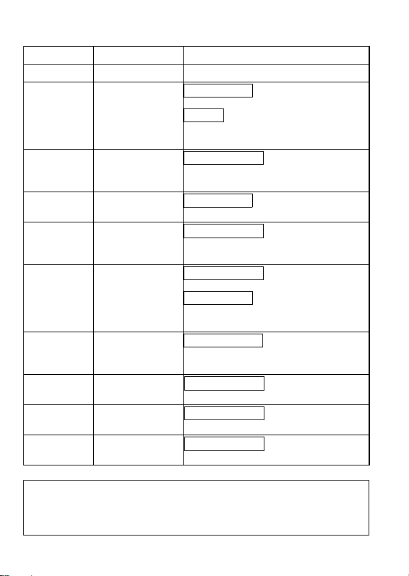
Packing List
The following items are included.
Model Product Quantity
CC-Link communication unit 1
Mounting screw set (2 screws, 2 stickers) 2
Extension interface relay board 1
Terminating resistor 110 1/2W (brown, brown,
1
brown)*
1
Plate type solderless terminal set
GT15-J61BT13
Terminating resistor 130 1/2W (brown, orange,
2
brown)*
1
Plate type solderless terminal set
Solderless terrninal (For connecting the braid
shield wire, Plate type)
2
Terminal block socket 1
GOT2000/GOT1000 Series CC-Link
Communication Unit User's Manual (This manual)
*1 Use it when using the Ver.1.10 compatible CC-Link dedicated cable/
Ver.1.00 compatible CC-Link dedicated cable.
*2 Use it when using the Ver.1.00 compatible CC-Link dedicated high-
performance cable.
A-10
1
Page 12

1. OVERVIEW
This user's manual describes the GOT2000/GOT1000 series CC-Link
communication unit (hereinafter referred to as the CC-Link communication unit) to
be used in the Control & Communication Link (CC-Link) system.
For attachable GOTs, refer to the User's Manual for the GOT used.
The CC-Link communication unit can be connected to the GOT, which can
perform monitoring as an intelligent device station (number of occupied stations
selectable from 1 station / 4 stations) in the CC-Link system.
The PLC CPU on the Master/local station of
Monitoring by
Transient
Transmission
Monitoring by
Cyclic
Transmission
When using the CC-Link connection, make the communication setting to perform
communication with PLCs.
For the details of the CC-Link connection, refer to the GOT2000 or GOT1000
Series Connection Manual (Mitsubishi Products).
the CC-Link system can be monitored.
Intelligent device
station
Remote device
station
All remote inputs/outputs and remote
registers assigned to the Master station
by CC-Link parameter setting can be
monitored.
Local station Master station
CC-Link
dedicated cable
1
Page 13

2. SPECIFICATIONS
2.1 Performance Specifications
The following is the performance specification of CC-Link communication unit.
The general specification of the CC-Link communication unit are the same as
those of the GOT.
For the general specifications of the GOT refer to the User's Manual for the GOT
1
used.
*
Item Specifications
CC-Link station type Intelligent device station
Number of occupied stations May be selected between 1 and 4.
Ver.2
Maximum number of link
points per system
Number of link points per station Refer to *3
Number of link points per number of
occupied stations
Transmission speed 156kbps/625kbps/2.5Mbps/5Mbps/10Mbps
Max. transmission distance Depends on the transmission speed.
Max. number of modules connected
Connection cable CC-Link dedicated cable
Internal current consumption
(5VDC)
Weight 0.18kg (0.40Ib)
mode
Ver.1
mode
Remote I/O(RX, RY)*
Remote register(RWw) 2048 points
Remote register(RWr) 2048 points
Remote I/O(RX, RY)*
Remote register(RWw) 256 points
Remote register(RWr) 256 points
The max. number of modules connected depends on the
configuration of the CC-Link system to be used.
For more details on the max. number of modules
connected, refer to the CC-Link System Master-Local
Module User’s Manual.
*1 When installing an extension unit on the CC-Link communication
unit, limit the maximum operating ambient temperature by
subtracting 5 degrees from operating ambient temperature of the
general specifications.
*2 Each of the I/O signals (RX, RY) occupies 16 points of a system
area within device points.
For more details on the I/O signals, refer to Section 3.1.
2
2
Refer to *4
26
0.56A
8192 points
2048 points
2
Page 14

*3 The number of link points per station depends on the mode setting of
CC-Link as shown below.
For CC-Link Ver.2
Number of link points per station
Link device
Single Double Quadruple Octuple
Remote I/O(RX, RY) 32 points 32 points
Remote register(RWw) 4 points 8 points
Remote register(RWr) 4 points 8 points 16 points 32 points
Extension cyclic setting
64 points 128 points
16 points 32 points
For CC-Link Ver.1
Link device Number of link points per station
Remote I/O(RX, RY) 32 points
Remote register(RWw) 4 points
Remote register(RWr) 4 points
*4 The number of link points per number of occupied stations depends
on the mode setting of CC-Link as shown below.
For CC-Link Ver.2
Number of link points per station
Extension cyclic setting
Link device
Remote I/O(RX, RY)
Remote register(RWw)
Remote register(RWr)
Single Double Quadruple Octuple
1
4
1
4
1
station
occup-
ied
32
points
4
points
4
points
station
station
occup-
occup-
ied
ied
128
32
points
points
16
points8 points
16
points8 points
station
occup-
ied
224
points
32
points
32
points
station
occup-
ied
64
points
16
points
16
points
4
station
occup-
ied
448
points
64
points
64
points
1
station
occup-
ied
128
points
32
points
32
points
station
occup-
points
points
points
For CC-Link Ver.1
Link device
Remote I/O(RX, RY) 32 points 128 points
Remote register(RWw) 4 points 16 points
Remote register(RWr) 4 points 16 points
Number of link points per station
1 station occupied 4 station occupied
4
ied
896
128
128
3
Page 15

2.2 Specifications of terminal block socket
Item Specifications
Screw tightening torgue
Recommended driver
Wiring screw
Terminal block fixing screw
Flat-blade screwdriver
(Blade thickness 0.6mm, Width 3.5mm)
: 0.5 to 0.6 N•m
: 0.7 to 0.8 N•m
4
Page 16

3. I/O SIGNALS AND REMOTE REGISTER ASSIGNMENT
3.1 I/O Signals Transferred to/from the Master Module
The following table lists the I/O signals assigned to the GOT.
The I/O signals differ according to the set number of occupied stations (1
or 4 stations).
n in the table indicates the address assigned to the Master module by
station number setting.
Signal Direction : GOT Master module
Device No.
Extension cyclic setting*
Single Double
1 station
occupied
RXn0
to RXnF
RX(n+1)0
to RX(n+1)A
RX(n+1)B RX(n+7)B RX(n+1)B RX(n+D)B
RX(n+1)C
to RX(n+1)F
1 station
occupied
RXn0
to RX(n+2)F
RX(n+3)0
to RX(n+3)A
RX(n+3)B RX(n+1B)B RX(n+7)B RX( n+37)B
RX(n+3)C
to RX(n+3)F
4 station
occupied
RXn0
to RX(n+6)F
RX(n+7)0
to RX(n+7)A
RX(n+7)C
to RX(n+7)F
Signal Direction : GOT Master module
Device No.
Quadruple Octuple
Extension cyclic setting*
4 station
occupied
RXn0
to RX(n+1A)F
RX(n+1B)0
to RX(n+1B)A
RX(n+1B)C
to RX(n+1B)F
1 station
occupied
RXn0
to RXnF
RX(n+1)0
to RX(n+1)A
RX(n+1)C
to RX(n+1)F
1 station
occupied
RXn0
to RX(n+6)F
RX(n+7)0
to RX(n+7)A
RX(n+7)C
to RX(n+7)F
1
1
4 station
occupied
RXn0
to RX(n+C)F
RX(n+D)0
to RX(n+D)A
RX(n+D)C
to RX(n+D)F
4 station
occupied
RXn0
to RX(n+36)F
RX(n+37)0
to RX(n+37)A
RX(n+37)C
to RX(n+37)F
Signal name
User area
Reserved
Remote READY
flag
Reserved
Signal name
User area
Reserved
Remote READY
flag
Reserved
*2
*2
5
Page 17

Signal Direction : GOT Master module
1 station
occupied
RYn0 to RYnF
RY(n+1)0
to RY(n+1)F
1 station
occupied
RYn0
to RY(n+2)F
RY(n+3)0
to RY(n+3)F
Device No.
Extension cyclic setting*
Single Double
4 station
occupied
RYn0
to RY(n+6)F
RY(n+7)0
to RY(n+7)F
Signal Direction : GOT Master module
Device No.
Extension cyclic setting*
Quadruple Octuple
4 station
occupied
RYn0
to RY(n+1A)F
RY(n+1B)0
to RY(n+1B)F
1 station
occupied
RYn0
to RYnF
RY(n+1)0
to RY(n+1)F
1 station
occupied
RYn0
to RY(n+6)F
RY(n+7)0
to RY(n+7)F
1
1
4 station
occupied
RYn0
to RY(n+C)F
RY(n+D)0
to RY(n+D)F
4 station
occupied
RYn0
to RY(n+36)F
RY(n+37)0
to RY(n+37)F
*1 When the mode setting of CC-Link is Ver.1, the extension cyclic
setting is not available. (Fixed to Single)
*2 The remote READY flag is on during startup of the GOT.
It switches on when GOT power is switched on, hardware reset is
made, or the GOT is ready to operate.
If GOT power is on, the remote READY flag is off when offline
operation is performed (during OS installation or screen data
downloading) or while initial processing is executed.
Use it for the interlock ladder when writing or reading data to or from
the CC-Link Master station.
Signal name
User area
Reserved
Signal name
User area
Reserved
6
Page 18

3.2 Remote Register Assignment
The following is the assignment of the remote registers of the GOT.
The remote registers differ according to the set number of occupied
stations (1 or 4 stations).
All areas are use areas.
m and n in the table indicate the addresses assigned to the Master
module by station number setting.
Address
Transfer
Direction
Master
station
GOT
GOT
Master
station
Transfer
Direction
Master
station
GOT
GOT
Master
station
1 station
occupied
RWwm to
RWwm+3
RWrn to
RWrn+3
1 station
occupied
RWwm to
RWwm+F
RWrn to
RWrn+F
Extension cyclic setting*
Single Double
4 station
occupied
RWwm to
RWwm+F
RWrn to
RWrn+F
Address
Extension cyclic setting*
Quadruple Octuple
4 station
occupied
RWwm to
RWwm+3F
RWrn to
RWrn+3F
*3 When the mode setting of CC-Link is Ver.1, the extension cyclic
setting is not available. (Fixed to Single)
1 station
occupied
RWwm to
RWwm+7
RWrn to
RWrn+7
1 station
occupied
RWwm to
RWwm+1F
RWrn to
RWrn+1F
3
RWwm to
RWwm+1F
RWrn+1F
3
RWwm to
RWwm+7F
RWrn+7F
4 station
occupied
RWrn to
4 station
occupied
RWrn to
Description
Description
User wirte
area
User read
area
User wirte
area
User read
area
Default
Value
0
0
Default
Value
0
0
7
Page 19

4. PART NAMES AND EXTERNAL DIMENSIONS
GT15-J61BT13
3
4)
98(3.86)
108(4.25)
3(0.12)
30.5(1.20)
21.5(0.85)
2.5
(0.10)
133(5.24)
1)
4)
8)
11
(0.43)
(0.12)
31.5(1.24)
GOT
3)
2)
5)
6)
20
(0.79)
X
7)
Unit: mm (inch)
Dimensions of X when the CC-Link communication unit is mounted to the GOT.
GOT GT27 GT25 GT16 GT15
15” 23(0.91) - 19.5(0.77) 21(0.83)
12.1” 23(0.91) 23(0.91) 18(0.71) 18(0.71)
10.4” 23(0.91) 23(0.91) 21(0.83) 21(0.83)
8.4” 23(0.91) 23(0.91) 23(0.91) 23(0.91)
5.7” 23(0.91) - 23(0.91) 23(0.91)
No. Name Description
CC-Link
1)
communication
connector
Interface
2)
connector
Extension
3)
connector
Mounting
4)
screw
Connector for connecting the CC-Link dedicated cable
Extension connector installed to a front extension unit or the GOT
Extension connector to which a back extension unit is installed
Mounting screws fixed with a front extension unit or the GOT
Unit:mm(inch)
8
Page 20

No. Name Description
LED name Status Details
RUN
OFF
The GOT is being
reset.
ON
The unit is in a
normal status.
ERR.
OFF
The unit is in a
normal status.
ON
The communication
statues of all stations
are abnormal.
Flicker
A communication
error has occurred at
a station or a station
number is
duplicated.
SD
OFF
Data have not been
transmitted or the
GOT is being reset.
ON
Data are being
transmitted.
RD
OFF
Data have not been
received or the GOT
is being reset.
ON
Data are being
received.
LED name Status Details
RUN
Flicker
The error mode has
been entered.
ON
OFF
No errors
ERR.
OFF
A starting error has
not occurred.
ON
A starting error has
occurred.
RD
OFF
A hardware failure
has not occurred.
ON
A hardware failure
has occurred.
Board fixing
5)
screw
Screw for fixing the extension interface relay board
6) Rating plate -
Terminal block
7)
socket
Operation
indicator LED
8)
SD
RD
Socket for connecting the CC-Link dedicated cable to the CC-Link
communication connector
This indicates the status of the CC-Link communication unit and the
communication status.
The LED lighting status includes the normal mode and error mode.
(1) Normal mode
If any communication
error occurs in the
normal mode, specify the
error cause by the
[NETWK unit status
display] screen.
Refer to the User's
Manual for the GOT used
for details on the
[NETWK unit status
display] screen.
(2) Error mode
When the RUN LED is
flickering, the LED
indication will change to
the error mode.
If an error occurs in the
error mode, restart the
GOT.
RUN
If the error mode is not
released after restarting
ERR.
the GOT, the system
alarm "460
Communication unit
error" may have
occurred.
For system alarms, refer
to the User's Manual for
the GOT used.
9
Page 21

Extension interface relay board
64(2.52)
24(0.94)
27.5(1.08)
Unit:mm(inch)
10
Page 22

5. INSTALLATION PROCEDURE
The installation procedure for the CC-Link communication unit is explained using
the GT1575.
5.1 CC-Link communication unit installation
(1) Power off the GOT.
(2) Remove two extension unit covers of the GOT.
(3) Attach the extend interface relay board to the extend I/F-2 side on the
GOT.
After the installation, detach the connector cover from the extend
interface relay board.
For the following GOT types, the extension interface relay board is not
needed.
•GT1655,155 of the GOT1000 series
•GT27,GT25 of the GOT2000 series
(4) Fit the CC-Link communication unit in the GOT case.
Remove the connector cover
4)
3)
11
Page 23

(5) Fasten the CC-Link communication unit by tightening its mounting
r
screws (4 places) with tightening torgue 0.36 to 0.48 N
•m.
(6) Fasten the bus connection unit by tightening the board fixing screws (2
places) with the tightening torque of 0.36 to 0.48 N
5) 6)
•m.
(7) When installing an extension unit on the unit that has been installed,
remove the connector cover and the sticker.
When not installing an extension unit on the unit that has been installed,
in order to avoid receiving electrostatic, stick accessory stickers to cover
the top of mounting screws (4 places).
Keep the connector cover fixed.
Keep the sticker stuck as it is.
Connector cover Accessory sticker
Sticke
Accessory sticker
POINT
Remove the screws that fixes the extension interface relay board before
removing the unit.(Above 6))
12
Page 24

5.2 Terminal block socket installation
CAUTION
Be sure to fix the wires or cables by ducts or clamps when connecting them to the
unit.
Not doing so can damage the unit or cables due to dangling, moved or accidentally
pulled cables or can cause misoperation due to cable contact fault.
(1) Insert the terminal block socket in the CC-Link communication unit.
A
(2) Fasten the terminal block by tightening the terminal block fixing screws (2
places) with the tightening torque of 0.7 to 0.8 N
(Expanded figure of part A)
A terminal block
fixing screw
•m.
POINT
When attaching or removing a communication cable to/from the terminal block
socket, detach the terminal block socket from the connector.
(When extension units are installed in multiple layers, the units do not have to be
removed from the GOT main unit.)
13
Page 25

6. WIRING METHOD
10mm
(0.39inch)
FG
SLD
DG
DB
DA
Braid
shield
Braid shield
Solderless terminal
(Plate type)
Next station
Previous station
The following diagram shows how to wire the GOT and CC-Link system modules.
(1) Wiring the GOT and CC-Link system modules by CC-Link dedicated
cable
Master module
DA
DB
Terminal
DG
resistor
SLD
FG
(Blue)
(Yellow)
(White)
CC-Link
dedicated
cable
GOT
DA
DB
DG
SLD
FG
When connecting the CC-Link dedicated cables of the previous station and next
station, strip the wire sheaths off for 10mm (0.39 inch) and insert the cables into
the terminal block socket with every two wires in the same color together.
When connecting the braid shields of the CC-Link dedicated cables of the
previous station and the next station, caulk each braid shield to the supplied
solderless terminal (Plate type), then insert the shields into the terminal block
socket.
I/O module, etc.
CC-Link
dedicated
cable
DA
DB
DG
SLD
FG
Terminal
resistor
14
Page 26

(2) When connecting the terminating resistor and FG cable
When connecting the terminating resistors to the GOT, be sure to
connect the terminating resistors (with the supplied plate type solderless
terminal) at the position as shown below.
When connecting the FG cable, strip the wire sheath of the FG cable
2
(2mm
) off for 10mm (0.39 inch) and insert it into the terminal block
socket.
DA
10mm
(0.39inch)
DB
DG
SLD
FG
(with plate type
solderless terminal)
Power supply cable
Conductor plate
Braid
shield
POINT
• Tighten the terminal block wiring screws with the tightening torque of 0.5 to 0.6
N
•m.
• Tighten terminal block mounting screws with the tightening torque of 0.7 to 0.8
N
•m.
• The terminating resistors supplied with the master module or the CC-Link communication unit must be connected to the PLC module or GOT at both ends of
the data link. (Connect them across DA-DB.)
• Connect the shield wire of the CC-Link dedicated cable to SLD of each module.
Since SLD is connected to FG internally, always ground the FG terminal and
FG1 terminal to the protective ground conductor.
• The FG terminal of the GOT power supply and the FG terminal of the CC-Link
Communication unit must be connected separately.
• When using the plate type solderless terminal, be sure to insert the terminal in
the horizontal direction toward the terminal block.
The solderless terminal may come off when it is inserted in the vertical direction.
Terminating resistor
15
Page 27

MEMO
16
Page 28

Warr anty
Mitsubishi will not be held liable for damage caused by factors found not to be the cause of
Mitsubis hi; machine dam age or lost profi ts caused by faults in the Mi tsubish i produc ts; dama ge,
secondary damage, accident compensation caused by special factors unpredictable by
Mitsubishi; damages to products other than Mitsubishi products; and to other duties.
For safe use
• This product has been manufactured as a general-purpose part for general industries, and
has not been designed or manufactured to be incorporated in a device or system used in
purposes related to human life.
• Bef ore using the product for special purposes such as nuclear po wer, electric power,
aerospace, medicine or passeng er movement vehicles, consult with Mitsubishi.
• This product has been manufactured under strict quality control. However, when installing the
product where major accidents or losses could occur if the product fails, install appropriate
backup or failsafe functions in the system.
Country/Region Sales office/Tel Country/Region Sales office/Tel
USA
Brazil
Mexico
Germany
UK
Italy
Spain
France
Czech
Turkey
Poland
Russia
Mitsubishi Electric Automation, Inc.
500 Corporate Woods Parkway, Vernon Hills,
IL 60061, U.S.A.
Tel: +1-847-478-2100
Mitsubishi Electric do Brasil Comercio e
Servicos Ltda.
Avenida Adelino Cardana, 293, 21 andar,
Bethaville, Barueri SP, Brasil CEP 06401-147
Tel: +55-11-4689-3000
Mitsubishi Electric Automation, Inc. Mexico
Branch
Mariano Escobedo #69, Col. Zona Industrial,
Tlalnepantla Edo. Mexico, C.P.54030
Tel: +52-55-3067-7511
Mitsubishi Electric Europe B.V. German Branch
Mitsubishi-Electric-Platz 1, 40882 Ratingen,
Germany
Tel: +49-2102-486-0
Mitsubishi Electric Europe B.V. UK Branch
Travellers Lane, Hatfield, Hertfordshire,
AL10 8XB, U.K.
Tel: +44-1707-28-8780
Mitsubishi Electric Europe B.V. Italian Branch
Centro Direzionale Colleoni - Palazzo Sirio,
Viale Colleoni 7, Agrate Brianza (MB), Italy
Tel: +39-039-60531
Mitsubishi Electric Europe B.V. Spanish Branch
Carretera de Rubi 76-80-Apdo.420, 08190 Sant
Cugat del Valles (Barcelona), Spain
Tel: +34-935-65-3131
Mitsubishi Electric Europe B.V. French Branch
25, Boulevard des Bouvets, 92741 Nanterre
Cedex, France
Tel: +33-1-55-68-55-68
Mitsubishi Electric Europe B.V. Czech Branch
Avenir Business Park, Radlicka 751/113e,
158 00 Praha 5, Czech Republic
Tel: +420-251-551-470
Mitsubishi Electric Turkey A.S. Umraniye
Branch
Serifali Mahallesi Nutuk Sokak No:5, TR-34775
Umraniye / Istanbul, Turkey
Tel: +90-216-526-3990
Mitsubishi Electric Europe B.V. Polish Branch
ul. Krakowska 50, 32-083 Balice, Poland
Tel: +48-12-347-65-00
Mitsubishi Electric (Russia) LLC St. Petersburg
Branch
Piskarevsky pr. 2, bld 2, lit “Sch”, BC “Benua”,
office 720;
RU-195027 St. Petersburg, Russia
Tel: +7-812-633-3497
South Africa
China
Taiwan
Korea
Singapore
Thailand
Indonesia
Vietnam
India
Australia
Adroit Technologies
20 Waterford Office Park, 189 Witkoppen
Road, Fourways, Johannesburg, South Africa
Tel: +27-11-658-8100
Mitsubishi Electric Automation (China) Ltd.
No.1386 Hongqiao Road, Mitsubishi Electric
Automation Center, Shanghai, China
Tel: +86-21-2322-3030
SETSUYO ENTERPRISE CO., LTD.
6F, No.105, Wugong 3rd Road, Wugu District,
New Taipei City 24889, Taiwan
Tel: +886-2-2299-2499
Mitsubishi Electric Automation Korea Co., Ltd.
7F-9F, Gangseo Hangang Xi-tower A, 401,
Yangcheon-ro, Gangseo-Gu, Seoul 07528,
Korea
Tel: +82-2-3660-9530
Mitsubishi Electric Asia Pte. Ltd.
307 Alexandra Road, Mitsubishi Electric
Building, Singapore 159943
Tel: +65-6473-2308
Mitsubishi Electric Factory Automation
(Thailand) Co., Ltd.
12th Floor, SV.City Building, Office Tower 1,
No. 896/19 and 20 Rama 3 Road, Kwaeng
Bangpongpang, Khet Yannawa, Bangkok
10120, Thailand
Tel: +66-2682-6522 to 31
PT. Mitsubishi Electric Indonesia
Gedung Jaya 11th Floor, JL. MH. Thamrin
No.12, Jakarta Pusat 10340, Indonesia
Tel: +62-21-3192-6461
Mitsubishi Electric Vietnam Co., LTD.
Ho Chi Minh Head Office
Unit 01-04, 10th Floor, Vincom Center, 72 Le
Thanh Ton Street, District 1, Ho Chi Minh City,
Vietnam
Tel: +84-8-3910-5945
Mitsubishi Electric India Pvt. Ltd. Pune Branch
Emerald House, EL -3, J Block, M.I.D.C.,
Bhosari, Pune - 411026, Maharashtra, India
Tel: +91-20-2710-2000
Mitsubishi Electric Australia Pty. Ltd.
348 Victoria Road, P.O. Box 11, Rydalmere,
N.S.W. 2116, Australia
Tel: +61-2-9684-7777
HEAD OFFICE : TOKYO BUILDING, 2-7-3 MARUNOUCHI, CHIYODA-KU, TOKYO 100-8310, JAPAN
NAGOYA WORKS : 1-14, YADA-MINAMI 5-CHOME, HIGASHI-KU, NAGOYA, JAPAN
When exported from Japan, this manual does not require application to the Ministry of Economy,
Trade and Industry for service transaction permission.
Specifications subject to change without notice. Printed in Japan, April 2017.
 Loading...