

Page 1

General-Purpose AC Servo
MODEL
Servo Motor
INSTRUCTION MANUAL
L
Page 2
Safety Instructions
(Always read these instructions before using the equipment.)
Do not attempt to install, operate, maintain or inspect the servo amplifier and servo motor until you have read
through this Instruction Manual, MELSERVO Servo Amplifier Installation Guide/Instruction Manual and
appended documents carefully and can use the equipment correctly. Do not use the servo amplifier and servo
motor until you have a full knowledge of the equipment, safety information and instructions.
In this Instruction Manual, the safety instruction levels are classified into "WARNING" and "CAUTION".
Indicates that incorrect handling may cause hazardous conditions,
WARNING
CAUTION
Note that the CAUTION level may lead to a serious consequence according to conditions. Please follow the
instructions of both levels because they are important to personnel safety.
What must not be done and what must be done are indicated by the following diagrammatic symbols.
resulting in death or severe injury.
Indicates that incorrect handling may cause hazardous conditions,
resulting in medium or slight injury to personnel or may cause physical
damage.
: Indicates what must not be done. For example, "No Fire" is indicated by
: Indicates what must be done. For example, grounding is indicated by
In this Instruction Manual, instructions at a lower level than the above, instructions for other functions, and so
on are classified into "POINT".
After reading this installation guide, always keep it accessible to the operator.
.
.
A - 1
Page 3
1. To prevent electric shock, note the following
WARNING
Before wiring or inspection, turn off the power and wait for 15 minutes or more until the charge lamp turns
off. Then, confirm that the voltage between P and N is safe with a voltage tester and others. Otherwise,
an electric shock may occur. In addition, always confirm from the front of the servo amplifier, whether the
charge lamp is off or not.
Connect the servo amplifier and servo motor to ground.
Any person who is involved in wiring and inspection should be fully competent to do the work.
Do not attempt to wire the servo amplifier and servo motor until they have been installed. Otherwise, you
may get an electric shock.
Operate the switches with dry hand to prevent an electric shock.
The cables should not be damaged, stressed loaded, or pinched. Otherwise, you may get an electric
shock.
During power-on or operation, do not open the front cover of the servo amplifier. You may get an electric
shock.
Do not operate the servo amplifier with the front cover removed. High-voltage terminals and charging area
are exposed and you may get an electric shock.
Except for wiring or periodic inspection, do not remove the front cover of the servo amplifier even if the
power is off. The servo amplifier is charged and you may get an electric shock.
2. To prevent fire, note the following.
CAUTION
Install the servo amplifier, servo motor and regenerative resistor on incombustible material. Installing them
directly or close to combustibles will lead to a fire.
Always connect a magnetic contactor (MC) between the main circuit power supply and L1, L2, and L3 of
the servo amplifier, and configure the wiring to be able to shut down the power supply on the side of the
servo amplifier’s power supply. If a magnetic contactor (MC) is not connected, continuous flow of a large
current may cause a fire when the servo amplifier malfunctions.
When a regenerative resistor is used, use an alarm signal to switch main power off. Otherwise, a
regenerative transistor fault or the like may overheat the regenerative resistor, causing a fire.
3. To prevent injury, note the follow
CAUTION
Only the voltage specified in the Instruction Manual should be applied to each terminal, Otherwise, a
burst, damage, etc. may occur.
Connect the terminals correctly to prevent a burst, damage, etc.
Ensure that polarity ( , ) is correct. Otherwise, a burst, damage, etc. may occur.
Take safety measures, e.g. provide covers, to prevent accidental contact of hands and parts (cables, etc.)
with the servo amplifier heat sink, regenerative resistor, servo motor, etc. since they may be hot while
power is on or for some time after power-off. Their temperatures may be high and you may get burnt or a
parts may damaged.
During operation, never touch the rotating parts of the servo motor. Doing so can cause injury.
A - 2
Page 4
4. Additional instructions
The following instructions should also be fully noted. Incorrect handling may cause a fault, injury, electric
shock, etc.
(1) Transportation and installation
CAUTION
Transport the products correctly according to their weights.
Use the eye-bolt of the servo motor to only transport the servo motor and do not use it to transport in the
condition to have installed a servo motor on the machine.
Stacking in excess of the specified number of products is not allowed.
Do not carry the servo motor by the cables, shaft or encoder.
Do not hold the front cover to transport the servo amplifier. The servo amplifier may drop.
Install the servo amplifier in a load-bearing place in accordance with the Instruction Manual.
Do not climb or stand on servo equipment. Do not put heavy objects on equipment.
The servo motor must be installed in the specified direction.
Leave specified clearances between the servo amplifier and control enclosure walls or other equipment.
Do not install or operate the servo motor which has been damaged or has any parts missing.
Do not block the intake/exhaust port of the servo motor which has a cooling fan.
Provide adequate protection to prevent screws and other conductive matter, oil and other combustible matter
from entering the servo amplifier and servo motor.
Do not drop or strike servo motor. Isolate from all impact loads.
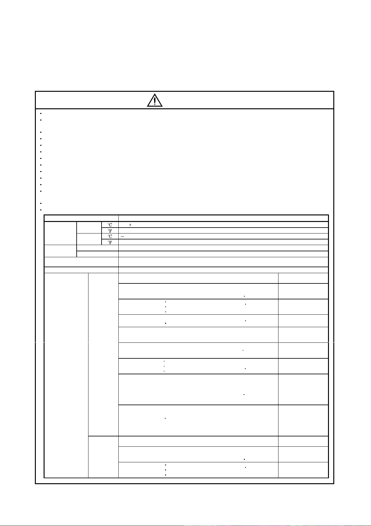
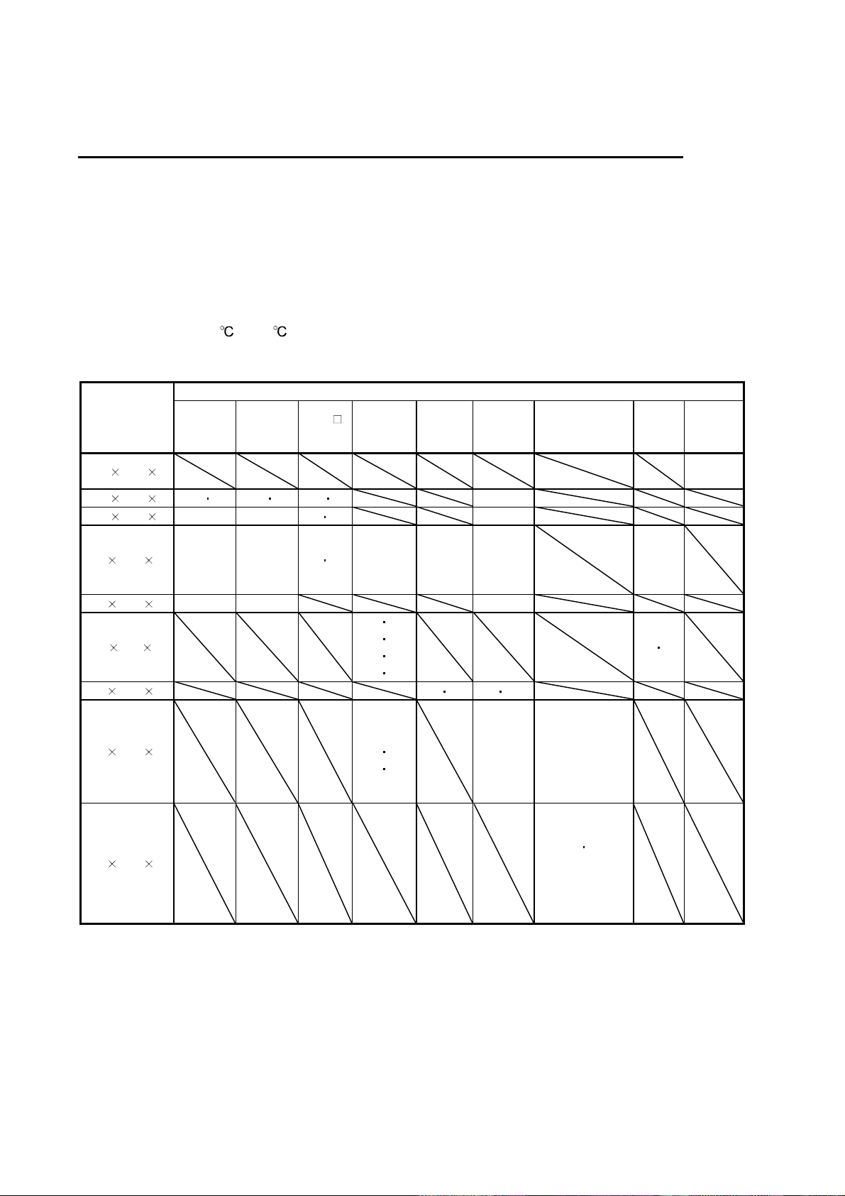
When you keep or use it, please fulfill the following environmental conditions.
Environment Conditions
In
Ambient
temperature
Ambient
humidity
Ambience
Altitude Max. 1000m (3280 ft) above sea level
(Note) Vibration
Operation
In Storage
In Operation 80%RH or less (non-condensing)
In Storage 90%RH or less (non-condensing)
[ ] 0 to 40 (non-freezing)
[
] 32 to 104 (non-freezing)
[ ] 15 to 70 (non-freezing)
[
] 5 to 158 (non-freezing)
Indoors (no direct sunlight)
Free from corrosive gas, flammable gas, oil mist, dust and dirt
HC-KFS series
HC-MFS series
HC-SFS52 to 152
HC-SFS53 to 153
HC-SFS121 201
HC-SFS202
HC-SFS203
HC-SFS502
HC-AQ series
HC-KF series
HC-MF series
[m/s2]
[ft/s
2
]
HC-SF52 to 152
HC-SF53 to 153
HC-SF121 201
HC-SF202
HC-SF203
HA-LFS601
HA-LFS701M to 15K1M
HA-LFS502 to 22K2
HA-LFS6014 to 12K14
HA-LFS701M4 to 15K1M4
HA-LFS11K24 to 22K24
HA-LFS15K1
HA-LFS22K1M
HA-LFS30K2
HA-LFS15K14 to 37K14
HA-LFS22K1M4 to 50K1M4
HA-LFS30K24 to 55K24
HC-KFS series
HC-MFS series
HC-SFS52 to 152
HC-SFS53 to 153
HC-SFS121
HC-SFS202
HC-SFS203
HC-SFS81
HC-SFS301
HC-SF81
to
to
to
HC-SFS81
352
353
702
352
353
12K1
37K1
37K1M
37K2
201
352
353
HC-UFS13 to 73 X,Y:49
HC-SFS524 to 1524
HC-RFS series
HC-UFS72
HC-SFS2024
HC-UFS202 to 502
HC-SFS5024
HA-FF series
HC-UF13 to 73
HC-RF series
HC-UF72
HC-LFS52
HC-UF202 to 502
HC-LFS202
HA-LH11K2
HC-SF301
HC-SF502
HA-LF series X,Y:9.8
HC-UFS13 to 73 X,Y:161
HC-SFS524 to 1524
HC-RFS series
HC-UFS72
HC-SFS2024
HC-UFS202 to 502
to
to
152
3524
7024
152
152
302
22K2
702
152
3524
X,Y:24.5
X:24.5
Y:49
X:24.5
Y:29.4
X,Y:19.6
X:9.8
Y:24.5
X:19.6
Y:49
X:11.7
Y:29.4
X,Y:80
X:80
Y:161
A - 3
Page 5
CAUTION
Environment Conditions
(Note) Vibration [ft/s2]
HA-LFS22K1M4 to 50K1M4
Note. Except the servo motor with reduction gear.
HC-SFS301
HC-SFS502
HC-AQ series
HC-KF series
HC-MF series
HC-SF81
HC-SF52 to 152
HC-SF53 to 153
HC-SF121 201
HC-SF202
HC-SF203
HA-LFS601
HA-LFS701M to 15K1M
HA-LFS502 to 22K2
HA-LFS6014 to 12K14
HA-LFS701M4 to 15K1M4
HA-LFS11K24 to 22K24
HA-LFS15K1
HA-LFS22K1M
HA-LFS30K2
HA-LFS15K14 to 37K14
HA-LFS30K24 to 55K24
to
to
to
702
352
353
12K1
37K1
37K1M
37K2
to
to
7024
152
152
302
22K2
702
HC-SFS5024
HA-FF series
HC-UF13 to 73
HC-RF series
HC-UF72
HC-LFS52
HC-UF202 to 502
HC-LFS202
HA-LH11K2
HC-SF301
HC-SF502
HA-LF series X,Y:32
X:80
Y:96
X,Y:64
X:32
Y:80
X:64
Y:161
X:38.4
Y:96.5
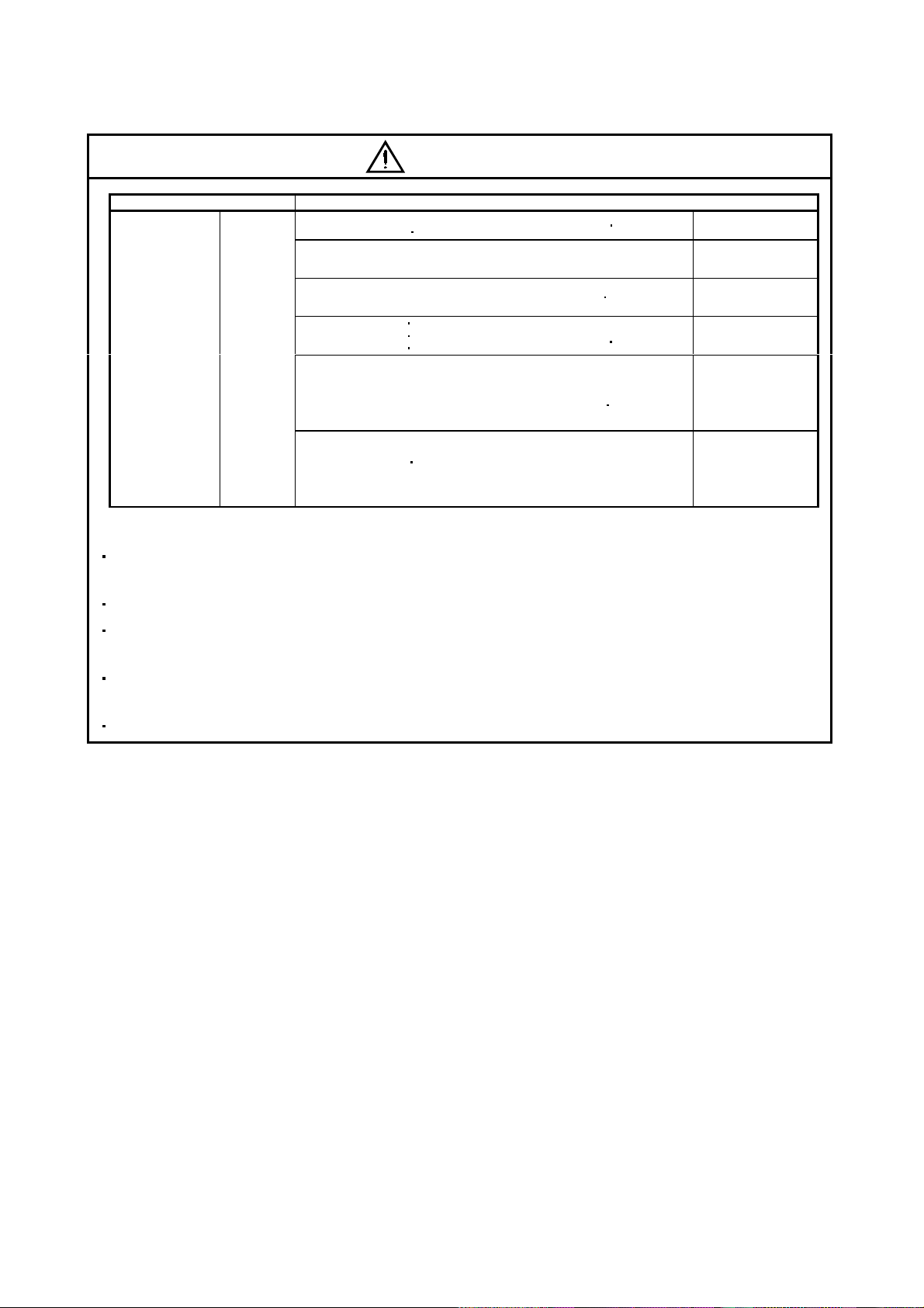
Securely attach the servo motor to the machine. If attach insecurely, the servo motor may come off during
operation.
The servo motor with reduction gear must be installed in the specified direction to prevent oil leakage.
Take safety measures, e.g. provide covers, to prevent accidental access to the rotating parts of the servo
motor during operation.
Never hit the servo motor or shaft, especially when coupling the servo motor to the machine. The encoder
may become faulty.
Do not subject the servo motor shaft to more than the permissible load. Otherwise, the shaft may break.
A - 4
Page 6
(2) Wiring
CAUTION
Wire the equipment correctly and securely. Otherwise, the servo motor may operate unexpectedly.
Do not install a power capacitor, surge absorber or radio noise filter (FR-BIF option) between the servo
motor and servo amplifier.
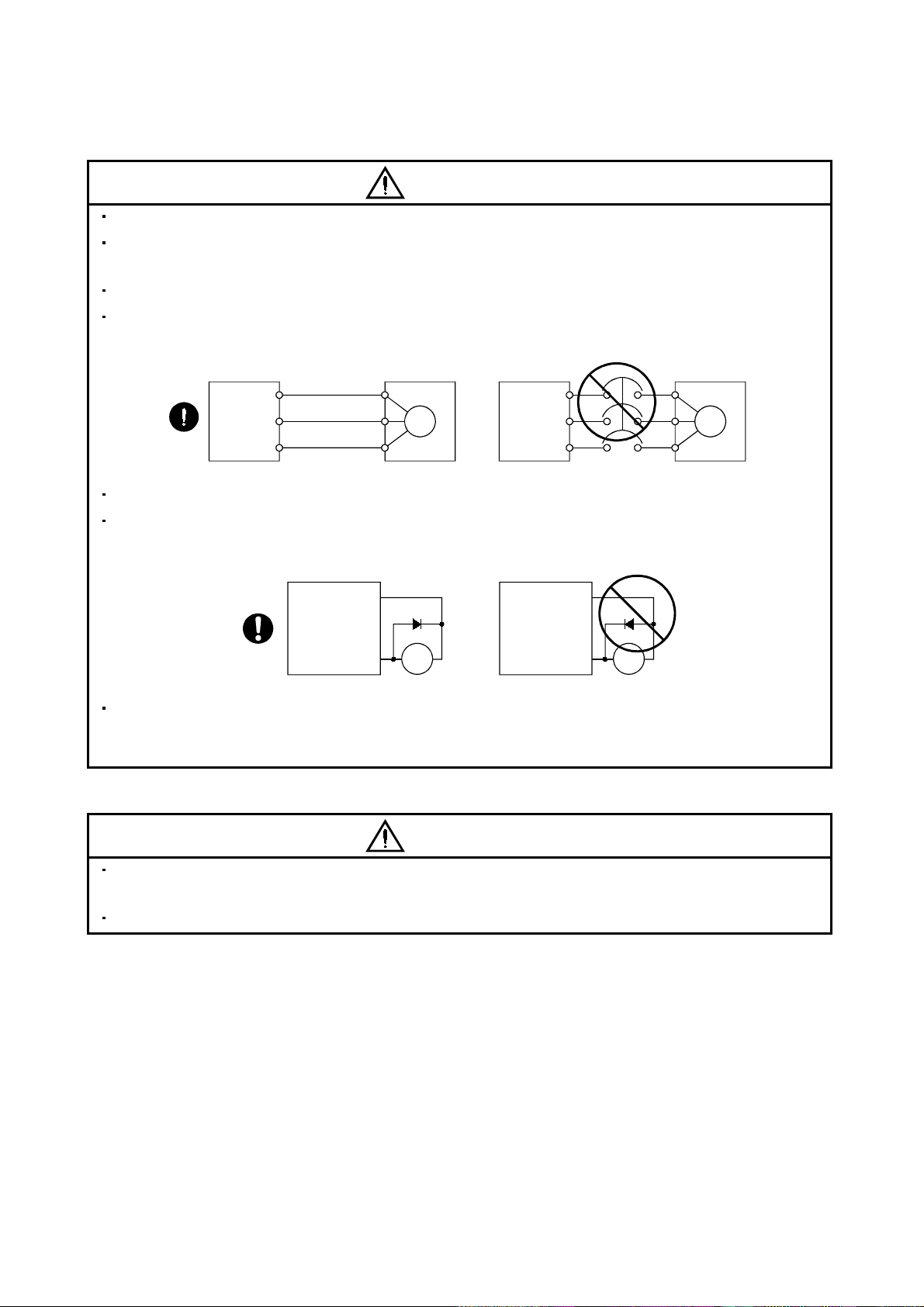
Connect the output terminals (U, V, W) correctly. Otherwise, the servo motor will operate improperly.
Connect the servo motor power terminal (U, V, W) to the servo motor power input terminal (U, V, W)
directly. Do not let a magnetic contactor, etc. intervene.
Servo amplifier
U
V
W
Servo motor
U
V
W
Servo motorServo amplifier
U
M
V
W
U
V
M
W
Do not connect AC power directly to the servo motor. Otherwise, a fault may occur.
The surge absorbing diode installed on the DC output signal of the servo amplifier relay must be wired in
the specified direction. Otherwise, the forced stop and other protective circuits may not operate.
Servo amplifier
VIN
(24VDC)
Control
output
signal
RA
Servo amplifier
VIN
(24VDC)
Control
output
signal
RA
When the cable is not tightened enough to the terminal block (connector), the cable or terminal block
(connector) may generate heat because of the poor contact. Be sure to tighten the cable with specified
torque.
(3) Test run adjustment
CAUTION
Before operation, check the parameter settings. Improper settings may cause some machines to perform
unexpected operation.
The parameter settings must not be changed excessively. Operation will be insatiable.
A - 5
Page 7
(4) Usage
CAUTION
Provide an external emergency stop circuit to ensure that operation can be stopped and power switched
off immediately.
Any person who is involved in disassembly and repair should be fully competent to do the work.
The STOP key of the parameter unit is only valid for test run. Provide an emergency stop key
independently of the STOP key. (MELSERVO-H series only)
Before resetting an alarm, make sure that the run signal into the servo amplifier is off to prevent an
accident. A sudden restart is made if an alarm is reset with the run signal on.
Do not modify the equipment.
Use a noise filter, etc. to minimize the influence of electromagnetic interference, which may be caused by
electronic equipment used near the servo amplifier.
Burning or breaking a servo amplifier may cause a toxic gas. Do not burn or break a servo amplifier.
Use the servo amplifier with the specified servo motor.
The electromagnetic brake on the servo motor is designed to hold the servo motor shaft and should not
be used for ordinary braking.
For such reasons as service life and mechanical structure (e.g. where a ball screw and the servo motor
are coupled via a timing belt), the electromagnetic brake may not hold the servo motor shaft. To ensure
safety, install a stopper on the machine side.
(5) Corrective actions
CAUTION
When it is assumed that a hazardous condition may take place at the occur due to a power failure or a
product fault, use a servo motor with electromagnetic brake or an external brake mechanism for the
purpose of prevention.
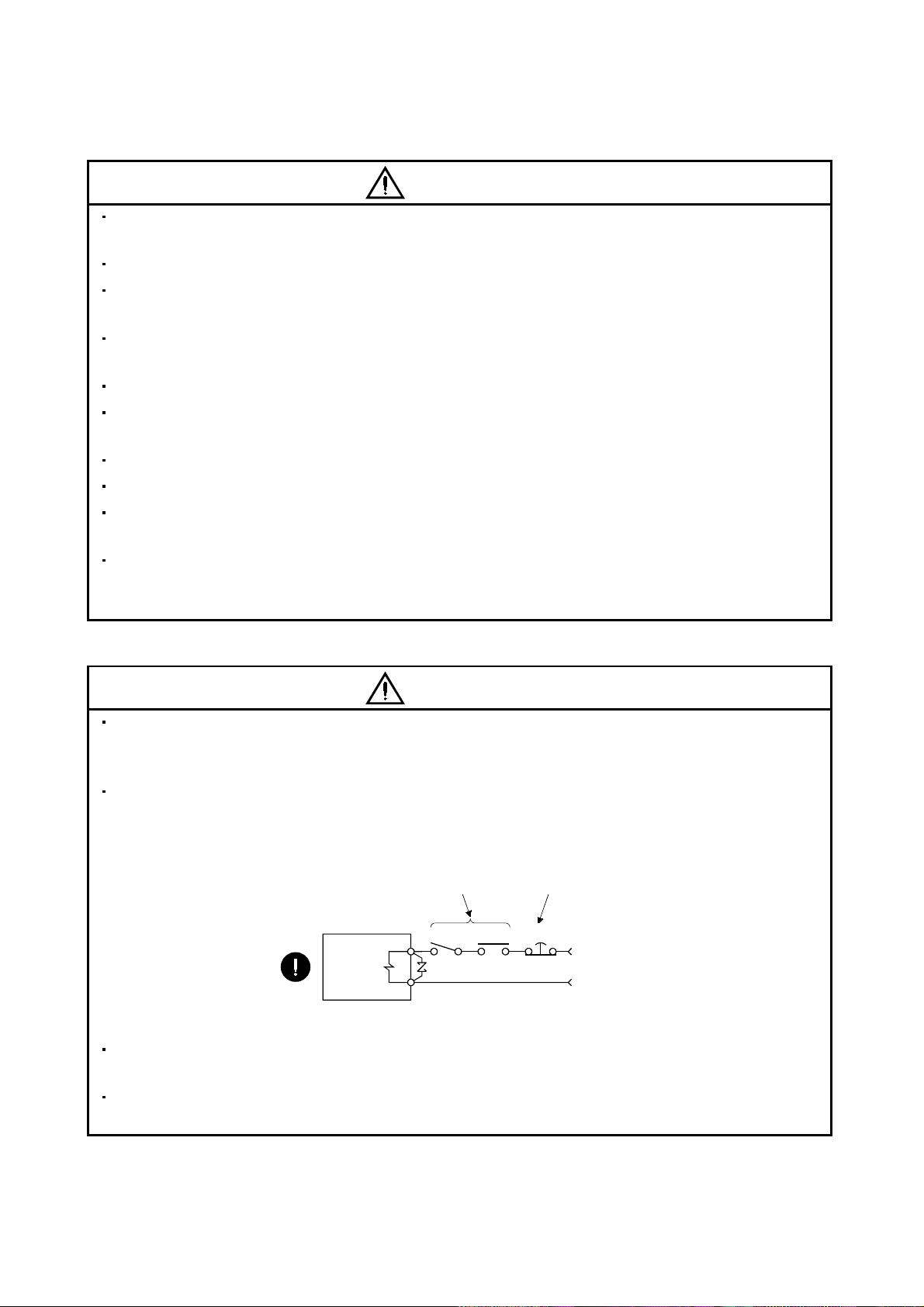
Configure the electromagnetic brake circuit so that it is activated not only by the servo amplifier signals
but also by an external emergency (forced) stop signal.
Contacts must be open when
servo-on signal is off, when an
alarm (trouble) is present and when
an electromagnetic brake signal.
Servo motor
Electromagnetic brake
SON RA
When any alarm has occurred, eliminate its cause, ensure safety, and deactivate the alarm before
restarting operation.
When power is restored after an instantaneous power failure, keep away from the machine because the
machine may be restarted suddenly (design the machine so that it is secured against hazard if restarted).
Circuit must be
opened during
emergency (force) stop.
EMG(EM1)
24VDC
A - 6
Page 8
(6) Maintenance, inspection and parts replacement
CAUTION
With age, the electrolytic capacitor of the servo amplifier will deteriorate. To prevent a secondary accident
due to a fault, it is recommended to replace the electrolytic capacitor every 10 years when used in general
environment.
Please consult our sales representative.
(7) Storage
CAUTION
Note the following points when storing the servo motor for an extended period of time (guideline: three or
more months).
Always store the servo motor indoors in a clean and dry place.
If it is stored in a dusty or damp place, make adequate provision, e.g. cover the whole product.
If the insulation resistance of the winding decreases, reexamine the storage method.
Though the servo motor is rust-proofed before shipment using paint or rust prevention oil, rust may be
produced depending on the storage conditions or storage period.
If the servo motor is to be stored for longer than six months, apply rust prevention oil again especially to
the machined surfaces of the shaft, etc.
Before using the product after storage for an extended period of time, hand-turn the motor output shaft to
confirm that nothing is wrong with the servo motor. (When the servo motor is equipped with a brake,
make the above check after releasing the brake with the brake power supply.)
When the equipment has been stored for an extended period of time, consult Mitsubishi.
(8) General instruction
CAUTION
To illustrate details, the equipment in the diagrams of this Instruction Manual may have been drawn
without covers and safety guards. When the equipment is operated, the covers and safety guards must
be installed as specified. Operation must be performed in accordance with this Instruction Manual.
A - 7
Page 9

About processing of waste
When you discard servo amplifier, a battery (primary battery), and other option articles, please follow the law of
each country (area).
FOR MAXIMUM SAFETY
These products have been manufactured as a general-purpose part for general industries, and have not
been designed or manufactured to be incorporated in a device or system used in purposes related to
human life.
Before using the products for special purposes such as nuclear power, electric power, aerospace,
medicine, passenger movement vehicles or under water relays, contact Mitsubishi.
These products have been manufactured under strict quality control. However, when installing the product
where major accidents or losses could occur if the product fails, install appropriate backup or failsafe
functions in the system.
EEP-ROM life
The number of write times to the EEP-ROM, which stores parameter settings, etc., is limited to 100,000. If
the total number of the following operations exceeds 100,000, the servo amplifier and/or converter unit may
fail when the EEP-ROM reaches the end of its useful life.
Write to the EEP-ROM due to parameter setting changes
Write to the EEP-ROM due to device changes
Precautions for Choosing the Products
Mitsubishi will not be held liable for damage caused by factors found not to be the cause of Mitsubishi;
machine damage or lost profits caused by faults in the Mitsubishi products; damage, secondary damage,
accident compensation caused by special factors unpredictable by Mitsubishi; damages to products other
than Mitsubishi products; and to other duties.
COMPLIANCE WITH EC DIRECTIVES
1. WHAT ARE EC DIRECTIVES?
The EC Directives were issued to standardize the regulations of the EU countries and ensure smooth
distribution of safety-guaranteed products. In the EU countries, the Machinery Directive (effective in
January, 1995), EMC Directive (effective in January, 1996) and Low Voltage Directive (effective in
January, 1997) of the EC Directives require that products to be sold should meet their fundamental safety
requirements and carry the CE marks (CE marking). CE marking applies to machines and equipment
into which servo amplifiers have been installed.
The servo amplifiers do not function independently but are designed for use with machines and
equipment.
Therefore, the CE marking does not apply to the servo amplifiers but applies to the machines and
equipment into which the servo amplifiers are installed.
This servo amplifier conforms to the standards related to the Low Voltage Directive to facilitate CE
marking on machines and equipment into which the servo amplifiers will be installed. To ensure ease of
compliance with the EMC Directive, Mitsubishi Electric prepared the "EMC INSTALLATION
GUIDELINES" (IB(NA)67310) which provides servo amplifier installation, control box making and other
procedures. Please contact your sales representative.
A - 8
Page 10
2. PRECAUTIONS FOR COMPLIANCE
Use the servo motor compatible with the EN Standard.
Unless otherwise specified, the handling, performance, specifications and others of the EN Standardcompatible models are the same as those of the standard models.
To comply with the EN Standard, also observe the following items strictly.
(1) Wiring
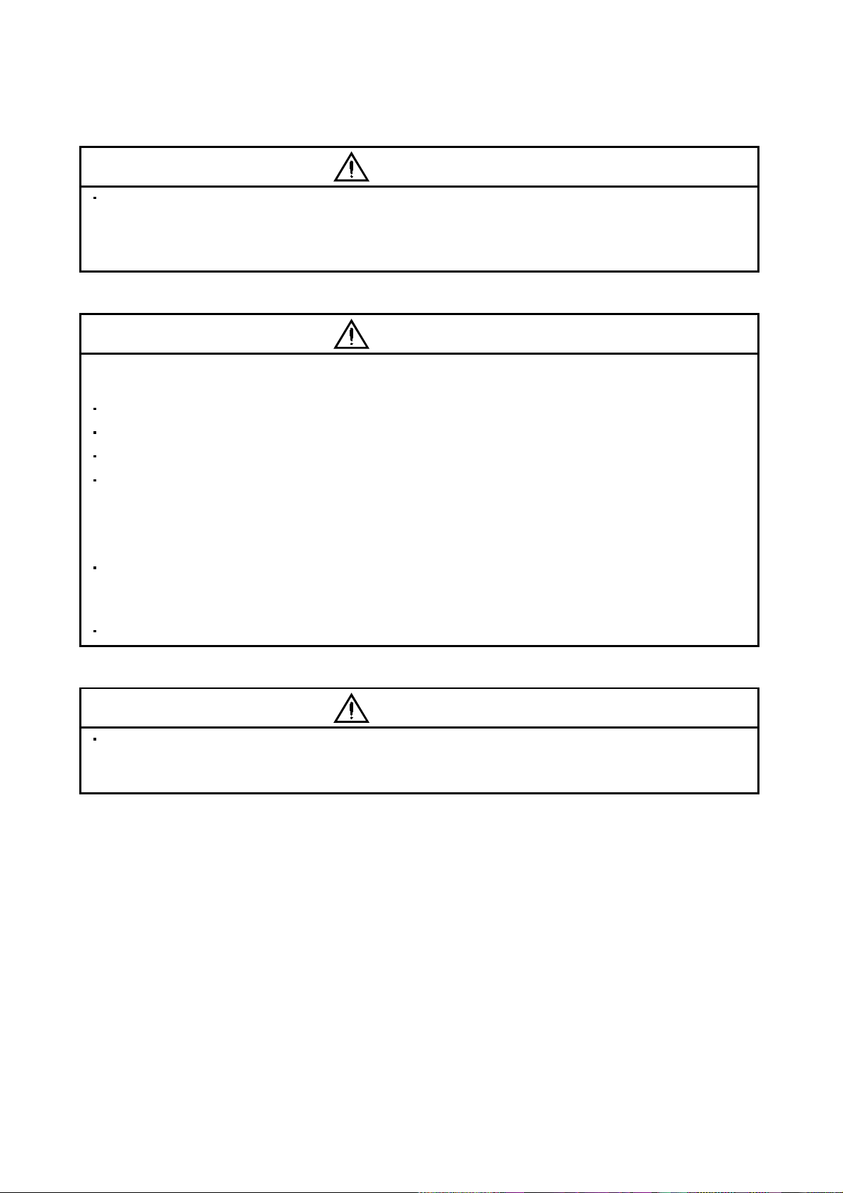
(a) Use a fixed terminal block to connect the power supply lead of the servo motor to the servo
amplifier. Do not connect cables directly.
Terminal block
(b) Use the servo motor side power connector which complies with the EN Standard.
The EN Standard-compliant power connector sets are available from us as options.
Power Connector Set Model Servo Motor Model
MR-PWCNF HC-FF C(B)-UE
MR-PWCNS1 HC-SF81(B)
MR-PWCNS2 HC-SF121(B) to 301(B)
MR-PWCNS3 HC-SF702(B) HC-SFS702(B)
HC-SF52(B) to 152(B)
HC-SF53(B) to 153(B)
HC-RF103(B) to 203(B)
HC-UF72(B)
HC-SFS81(B)
HC-SFS52(B) to 152(B)
HC-SFS53(B) to 153(B)
HC-SFS524(B) to 1524(B)
HC-RFS103(B) to 203(B)
HC-UFS72(B)
HC-LFS52(B)
HC-SF202(B) to 502(B)
HC-SF203(B)
HC-RF353(B)
HC-UF202(B) to 502(B)
HC-SFS121(B) to 301(B)
HC-SFS202(B) to 502(B)
HC-SFS203(B)
HC-SFS2024(B) to 5024(B)
HC-RFS353(B)
HC-UFS202(B) to 502(B)
HA-LFS502
HC-LFS202(B)
HC-SFS7024(B)
HA-LFS702
152(B)
152(B)
152(B)
to
353(B)
503(B)
353(B)
503(B)
302(B)
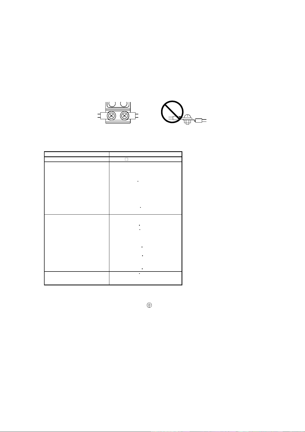
(2) Installation
The flange of the machine mounted with the HC-MF(HC-MF-UE)/HC-KF(HC-KF-UE)/HC-AQ/HCMFS/HC-KFS must be connected to the earth (
).
(3) Performing EMC tests
When EMC tests are run on a machine/device into which the servo motor has been installed, it must
conform to the electromagnetic compatibility (immunity/emission) standards after it has satisfied the
operating environment/electrical equipment specifications.
For the other EMC directive guidelines on the servo motor, refer to the EMC Installation Guidelines
(IB(NA)67310).
A - 9
Page 11
CONFORMANCE WITH UL/C-UL STANDARD
Use the UL/C-UL Standard-compliant model of servo motor.
Unless otherwise specified, the handling, performance, specifications, etc. of the UL/C-UL Standardcompliant models are the same as those of the standard models.
The servo motor is compliant with the UL/C-UL standard when it is mounted on the flanges made of
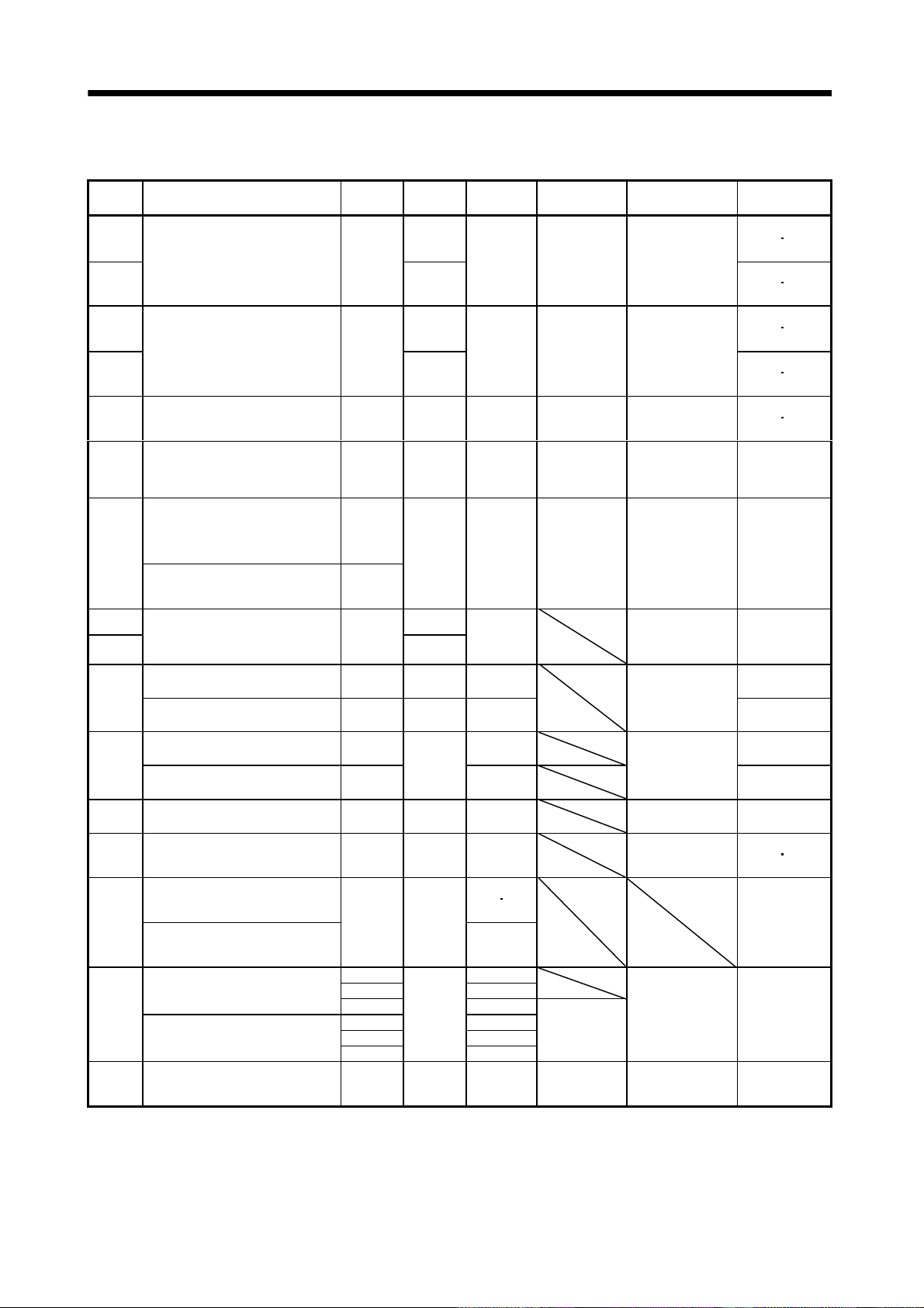
aluminum whose sizes are indicated in the following table.
The rated torque of the servo motor under the UL/C-UL standard indicates the continuous permissible
torque value that can be generated when it is mounted on the flange specified in this table and used in
the environment of 0
mount the servo motor on a flange with a heat radiating effect equivalent to that of this flange.
Flange Size
[mm]
150 150 3
150 150 6 053 13 053 13 053 13 13
250 250 623 23 2333 23
250 250 12 43 43 43 63
300 300 12 (Note 1) 73 73 73
300 300 20
550 550 30 353 503 72 152
650 650 35
950 950 35
Note 1. 73 is not available for the HC-KF(-UE) series.
2. 524 to 7024 are not available for the HC-SF series.
HC-KF(-UE)
HC-KFS
to 40 ambient temperature. Therefore, to conform to the UL/C-UL standard,
Servo Motor
HC-MF(-UE)
HC-MFS
HA-FF
-UE
(Note 2)
C
HC-SF
HC-SFS
81
52 to 152
53 to 153
524 to 1524
121
202
203
2024
301
502 702
5024
HC-RF
HC-RFS
103 to 203 43 52 to 152
201
352
353
3524
7024
HC-UF
HC-UFS
202 to 502
HA-LF
HA-LFS
601 to 12K1
701M to 15K1M
502 to 22K2
6014 to 12K14
701M4 to 15K1M4
11K24 to 22K24
15K1 to 37K1
22K1M to 37K1M
30K2
37K2
15K14 to 37K14
22K1M4 to
50K1M4
30K24 to 55K24
HC-LFS HC-AQ
0135 to
0335
302
202
A - 10
Page 12

CONTENTS
1. INTRODUCTION 1 - 1 to 1 -16
1.1 Servo motor features .............................................................................................................................. 1 - 1
1.2 Model name make-up............................................................................................................................. 1 - 2
1.3 Parts identification................................................................................................................................ 1 -15
2. INSTALLATION 2 - 1 to 2 -14
2.1 Environmental conditions...................................................................................................................... 2 - 2
2.2 Installation orientation ..........................................................................................................................2 - 4
2.3 Load remove precautions ....................................................................................................................... 2 - 4
2.4 Permissible load for the shaft................................................................................................................ 2 - 5
2.4.1 Without reduction gear ...................................................................................................................2 - 5
2.4.2 With reduction gear......................................................................................................................... 2 - 7
2.5 Protection from oil and water............................................................................................................... 2 -11
2.6 Cooling fan.............................................................................................................................................. 2 -13
2.7 Cable .......................................................................................................................................................2 -13
3. CONNECTORS USED FOR SERVO MOTOR WIRING 3 - 1 to 3 -20
3.1 Makeups ..................................................................................................................................................3 - 1
3.1.1 HC-KF(-UE)
3.1.2 HA-FF
3.1.3 HC-SF(S)
3.1.4 HC-AQ series................................................................................................................................... 3 -15
3.1.5 HC-KFS
3.1.6 HC-UF3000r/min series (Compliance with IP65) ....................................................................... 3 -16
3.2 IP65, EN Standard-compliant options ................................................................................................3 -17
3.3 Signal arrangement of encoder connectors ......................................................................................... 3 -19
4. INSPECTION 4 - 1 to 4 - 2
5. SPECIFICATIONS 5 - 1 to 5 -50
5.1 Standard specifications .......................................................................................................................... 5 - 1
5.2 Torque characteristics........................................................................................................................... 5 -23
5.3 Servo motors with reduction gears ......................................................................................................5 -41
5.4 Servo motors with special shafts.......................................................................................................... 5 -47
5.4.1 Keyway............................................................................................................................................. 5 -47
5.4.2 D cut .................................................................................................................................................5 -49
5.4.3 Straight (HC-AQ)............................................................................................................................ 5 -49
HC-MF(-UE) HA-FF HC-UF3000r/min series ................................................ 3 - 1
C-UE series........................................................................................................................ 3 - 1
HC-RF(S) HC-UF(S)2000r/min, HA-LH HA-LF HA-LFS HC-LFS series..... 3 - 7
HC-MFS HC-UFS3000r/min series ..........................................................................3 -15
6. CHARACTERISTICS 6 - 1 to 6 - 6
6.1 Electromagnetic brake characteristics .................................................................................................6 - 1
6.2 Vibration rank.........................................................................................................................................6 - 5
6.3 Machine accuracies................................................................................................................................. 6 - 6
1
Page 13

7. OUTLINE DIMENSION DRAWINGS 7 - 1 to 7 -306
7.1 Servo motors............................................................................................................................................ 7 - 1
7.1.1 HC-MF
7.1.2 HA-FF series ...................................................................................................................................7 -23
7.1.3 HC-SF
7.1.4 HC-RF
7.1.5 HC-UF 2000r/min
7.1.6 HC-UF 3000r/min series ..............................................................................................................7 -100
7.1.7 HC-UF3000r/min, HC-UFS3000r/min series with IP65-compliant connectors .....................7 -103
7.1.8 HA-LH series................................................................................................................................. 7 -106
7.1.9 HC-AQ series................................................................................................................................. 7 -108
7.1.10 HA-LF series ...............................................................................................................................7 -109
7.1.11 HC-MFS
7.1.12 HC-UFS 3000r/min series..........................................................................................................7 -132
7.1.13 HA-LFS series............................................................................................................................. 7 -135
7.1.14 HC-LFS series............................................................................................................................. 7 -144
7.2 Servo motors (in inches)......................................................................................................................7 -149
7.2.1 HC-MF
7.2.2 HA-FF series .................................................................................................................................7 -171
7.2.3 HC-SF
7.2.4 HC-RF
7.2.5 HC-UF 2000r/min
7.2.6 HC-UF 3000r/min series ..............................................................................................................7 -248
7.2.7 HC-UF3000r/min, HC-UFS3000r/min series with IP65-compliant connectors .....................7 -251
7.2.8 HA-LH series................................................................................................................................. 7 -254
7.2.9 HC-AQ series................................................................................................................................. 7 -256
7.2.10 HA-LF series ...............................................................................................................................7 -257
7.2.11 HC-MFS
7.2.12 HC-UFS 3000r/min series..........................................................................................................7 -280
7.2.13 HA-LFS series............................................................................................................................. 7 -283
7.2.14 HC-LFS series............................................................................................................................. 7 -292
7.3 Connector.............................................................................................................................................. 7 -297
HC-KF series....................................................................................................................7 - 1
HC-SFS series .................................................................................................................. 7 -50
HC-RFS series ................................................................................................................. 7 -90
HC-UFS 2000r/min series ........................................................................... 7 -97
HC-KFS series.......................................................................................................... 7 -113
HC-KF series................................................................................................................. 7 -149
HC-SFS series ................................................................................................................ 7 -198
HC-RFS series ............................................................................................................... 7 -238
HC-UFS 2000r/min series ......................................................................... 7 -245
HC-KFS series.......................................................................................................... 7 -261
8. CALCULATION METHODS FOR DESIGNING 8 - 1 to 8 -14
8.1 Specification symbol list......................................................................................................................... 8 - 1
8.2 Position resolution and electronic gear setting ...................................................................................8 - 2
8.3 Speed and command pulse frequency................................................................................................... 8 - 3
8.4 Stopping characteristics......................................................................................................................... 8 - 4
8.5 Capacity selection................................................................................................................................... 8 - 5
8.6 Load torque equations............................................................................................................................ 8 - 8
8.7 Expression for calculating the electromagnetic brake workload .......................................................8 - 8
8.8 Load inertia moment equations ............................................................................................................8 - 9
8.9 Precautions for zeroing .........................................................................................................................8 -10
8.10 Selection example ................................................................................................................................ 8 -11
2
Page 14

APPENDIX App.- 1 to App.- 3
App. 1 Servo motor ID codes................................................................................................................... App.- 1
App. 2 Change of connector sets to the RoHS compatible products ................................................... App.- 3
3
Page 15

MEMO
4
Page 16
1. INTRODUCTION
r
g
[p
]
g
1. INTRODUCTION
1.1 Servo motor features
Servo
Moto
Series
(Points Different from Conventional
Features
Products)
Rated
Speed
[r/min]
Positionin
Resolution
ulses/rev
Capacity
[kW]
Interchan
Servo Motor
Series
eable
Overseas Standards
Compliance with
Environmental
Resistance
HC-KF 8192 (Note1 2) IP44
HC-KFS
HC-MF 8192 (Note1 2) IP44
HC-MFS
HA-FF
HC-SF
HC-SFS
HC-RF 16384
HC-RFS
HC-UF
HC-UFS
HA-LH Low inertia, large capacity 2000 16384 11 to 22
HC-AQ
HA-LF
HA-LFS
HC-LFS
Low inertia, small capacity 4 to 5
times greater in inertia moment than
HC-MF(S).
Equipped with absolute position
detector as standard
Ultra low inertia, small capacity
1.2 times higher in power rate than
HA-ME
Equipped with absolute position
detector as standard
Low inertia, small capacity
Equipped with absolute position
detector as standard
Middle inertia, middle capacity
1.5 times higher in power rate than
HA-SE
Equipped with absolute position
detector as standard
Three-phase, 200VAC-compatible
Middle inertia, middle capacity 1.5
times higher in power rate than HASE
Equipped with absolute position
detector as standard
Three-phase, 400VAC-compatible
Middle inertia, middle capacity
Equipped with absolute position
detector as standard
Ultra low inertia, middle capacity
About 3 times higher in power rate
than HA-LH
Equipped with absolute position
detector as standard
Flat type, small capacity
Equipped with absolute position
detector as standard
Flat type, middle capacity
Equipped with absolute position
detector as standard
Flat type small capacity
Equipped with absolute position
detector as standard
Flat type middle capacity
Equipped with absolute position
detector as standard
24VDC-compatible,
compact size, small capacity
Three-phase, 200VAC-compatible,
low inertia, large capacity
Equipped with absolute position
detector as standard
Three-phase, 400VAC-compatible,
low inertia, large capacity
Equipped with absolute position
detector as standard
Three-phase, 200VAC-compatible,
low inertia, middle large capacity
Equipped with absolute position
detector as standard
Three-phase, 400VAC-compatible,
low inertia, large capacity
Equipped with absolute position
detector as standard
Low inertia, middle capacity
Equipped with absolute position
detector as standard
3000
131072
3000
131072
8192 3000 0.05 to 0.6
1000
2000
3000
1000
2000
3000
2000
3000
3000 8192 0.1 to 0.75 (Note1) IP65
2000 16384 0.75 to 5
3000 0.1 to 0.75 (Note1) IP65
2000
3000 8192 0.01 to 0.03
2000 16384
1000 6 to 37
1500 7 to 37
2000 5 to 37
1000 6 to 37
1500 7 to 50
2000
2000 131072 0.5 to 3 HA-LH
16384 0.5 to 7
131072 0.5 to 7
131072
131072
131072
0.05 to 0.4
0.05 to 0.75
1 to 5
0.75 to 5
30
37
30 to 55
11 to 55
HC-MF
HC-ME
HC-MH
HA-ME
HA-MH
HA-FE
HA-FH
HA-SE
HA-SH
HA-SE
HA-SH
HA-LH
EN Standard
UL/C-UL Standard
(Standard model is
compliant)
EN Standard
UL/C-UL Standard
(Standard model is
compliant)
EN Standard
UL/C-UL Standard
(HA-FF-UE is
compliant)
EN Standard
UL/C-UL
(Standard model is
compliant)
EN Standard
UL/C-UL
(Standard model is
compliant)
EN Standard
UL/C-UL Standard
(Standard model is
compliant)
EN Standard
UL/C-UL Standard
(Standard model is
compliant)
EN Standard
UL/C-UL Standard
(Standard model is
compliant)
EN Standard
(HA-LH-EC is
compliant)
EN Standard,
UL/C-UL Standard
(Standard model is
compliant)
EN Standard,
UL/C-UL Standard
(Standard model is
compliant)
EN Standard,
UL/C-UL Standard
(Standard model is
compliant)
(Note1 2) IP55
(Note1 2) IP55
2) IP44
(Note1
IP65
IP65
IP65
IP65
IP65
JP44
(Note1 2) IP55
IP44
IP44
IP65
Note 1. Except connector section.
2. Except for the shaft-through portion.
1 - 1
Page 17
1. INTRODUCTION
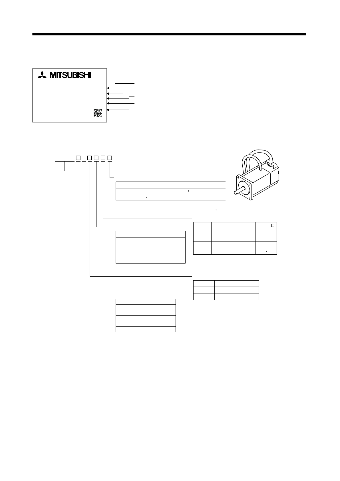
1.2 Model name make-up (1) Rating plate
AC SERVO MOTOR
HC-SF502G1H
INPUT 3AC 133V 26A
OUTPUT 5kW IEC60034-1 '99
2000r/min IP65CI.F 102kg
SER.No. AS958300202X
MITSUBISHI ELECTRIC CORPORATION
MADE IN JAPAN
Model
Input power
Rated output
Rated speed, Protection structure,
Insulation class, Mass
Serial number
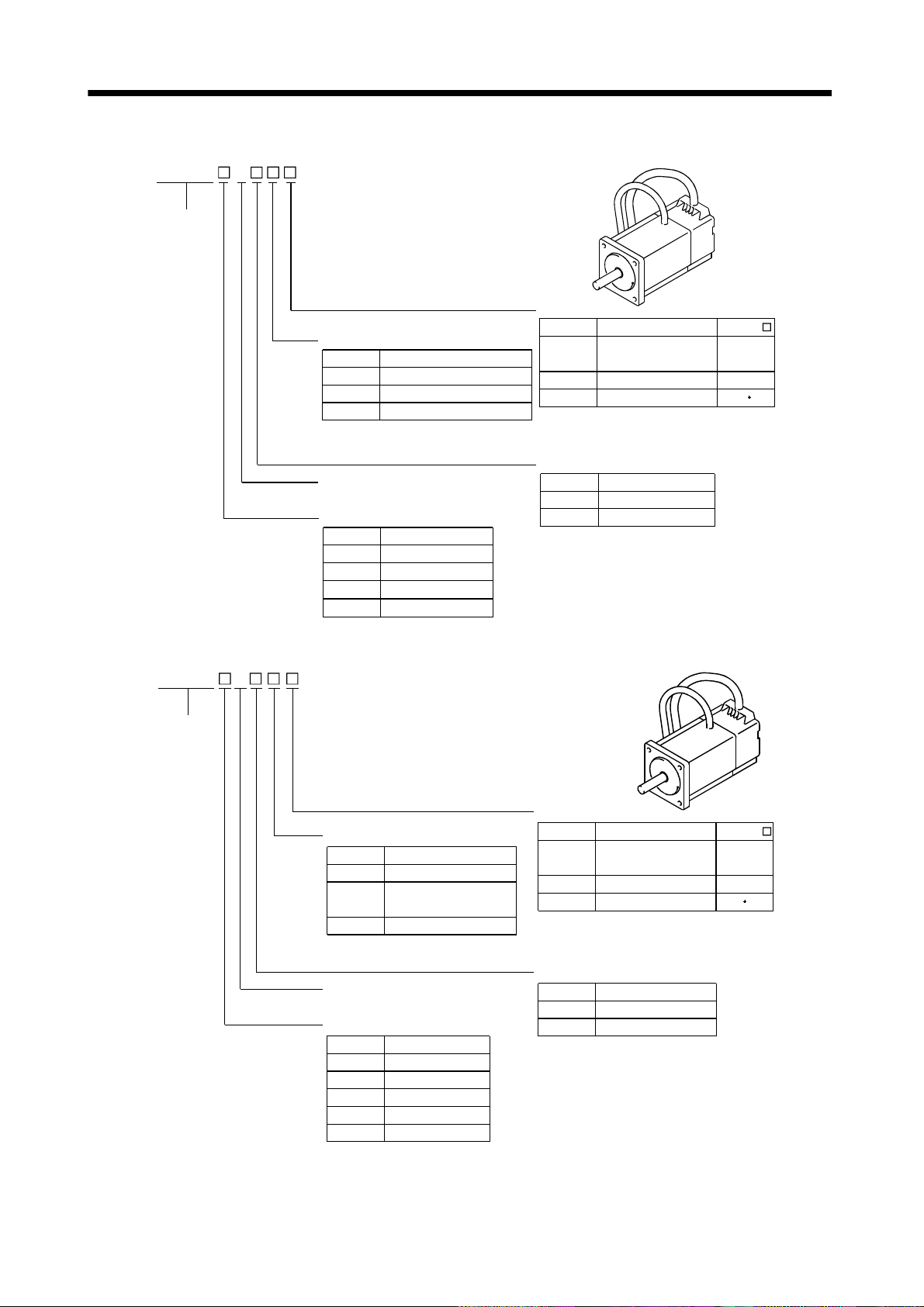
(2) Model
(a) HC-MF series (ultra low inertia, small capacity)
HC-MF
Series name
3
Compliance with Standard
Symbol
None
(Note) Standard model (EN UL/C-UL Standard)
-UE
EN UL/C-UL Standard
Note. The standard models produced in and after
February, 2001 are compatible with the EN UL/C-UL Standard.
Reduction gear
Symbol
None
G1
G2
Reduction Gear
For general
industrial machine
For precision application
Rated speed
3000 [r/min]
Rated output
Symbol
Rated Output [kW]
05
1
2
4
7
Without
0.05
0.1
0.2
0.4
0.75
Specifications
Appearance
Shaft type
Symbol
None
(Note) K
(Note) D
Note. The special shaft applies to the standard
Shaft Shape
Standard
(Straight shaft)
With keyway (With key)
D-cut shaft
servo motor and servo motor with
electromagnetic brake.
HC-MF
053 to 73
23 to 73
53 13
Electromagnetic brake
Symbol
Electromagnetic Brake
None
B
Without
With
1 - 2
Page 18
1. INTRODUCTION
(b) HA-FF series (low inertia, small capacity)
Series name
3 HA-FF
Appearance
Compliance with Standard
Symbol
None
-UE
Specifications
Standard model (Japan)
EN UL/C-UL Standard
Shaft type
Reduction gear
Symbol
None
G1
G2
For precision application
Reduction Gear
Without
For general
industrial machine
Symbol
None
(Note2) D
Note 1. The Standard shafts of the HA-FF23 to
63 are with keys and those of the other
models are straight shafts.
2. The special shaft applies to the standard
Shaft Shape
(Note1) Standard
D-cut shaft
servo motor and servo motor with
electromagnetic brake.
HA-FF
053 to 63
053 13
Electromagnetic brake
Input power supply form
Symbol
None
Standard model
Lead
C
EN UL/C-UL Standard-
compliant model
Cannon connector
Symbol
None
Electromagnetic Brake
B
Without
With
Rated speed
3000 [r/min]
Rated output
Symbol
05
1
2
Rated Output [kW]
0.05
0.1
0.2
Rated Output [kW]Symbol
3
4
6
0.3
0.4
0.6
1 - 3
Page 19
1. INTRODUCTION
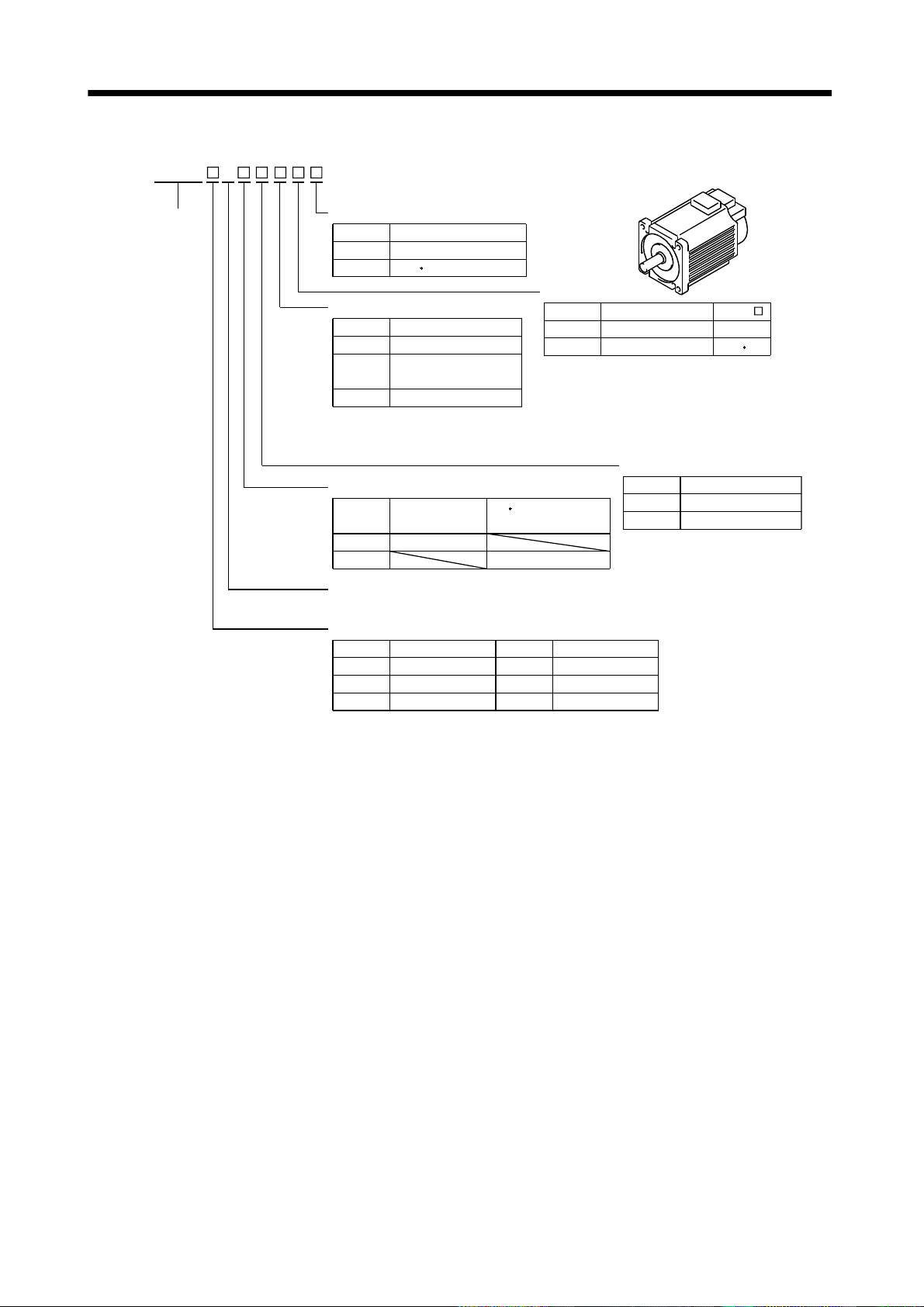
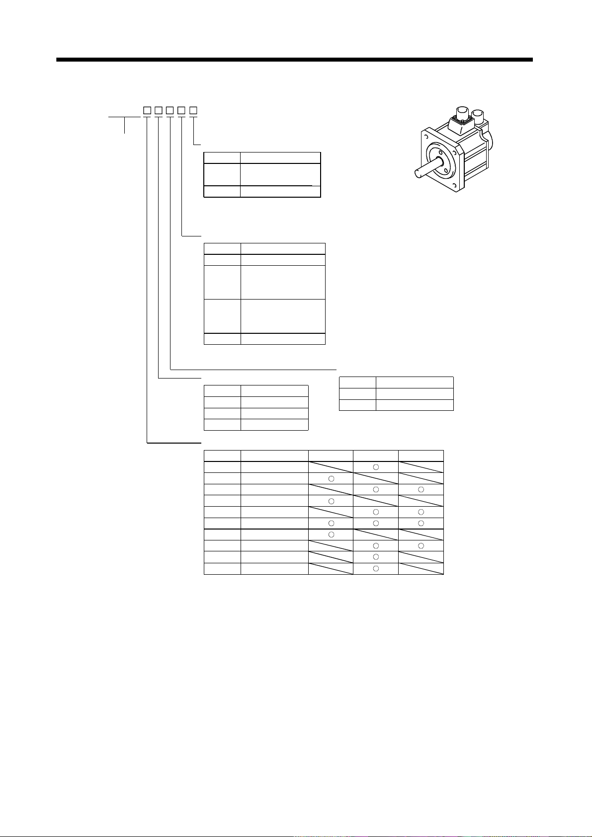
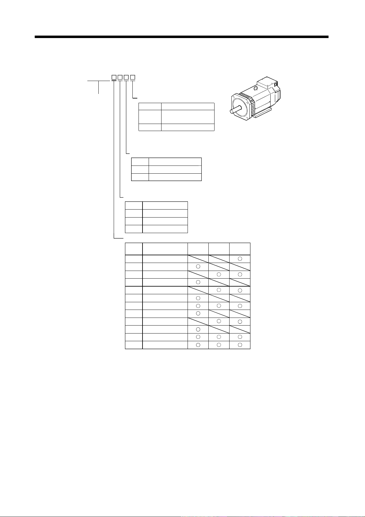
(c) HC-SF series (middle inertia, middle capacity)
HC-SF
Series name
Shaft type
Symbol
None
(Note) K
Note. The special shaft applies to the standard
servo motor and servo motor with
electromagnetic brake.
Shaft Shape
Standard
(Straight shaft)
With keyway (With key)
Reduction gear
Symbol
None Without
G1
G1H
Note. Not provided for 1000r/min and
3000r/min series.
(Note) Reduction Gear
For general
industrial machine
(flange type)
For general
industrial machine
(leg type)
For precision applicationG2
Rated speed
Symbol
1
2
3
Speed [r/min]
1000
2000
3000
Appearance
Electromagnetic brake
Symbol
None
Electromagnetic Brake
B
Without
With
Rated output
Symbol
5
8
10
12
15
20
30
35
50 5
70
Rated Output [kW]
0.5
0.85
1
1.2
1.5
2
3
3.5
7
1000 [r/min]
2000 [r/min]
3000 [r/min]
1 - 4
Page 20
1. INTRODUCTION
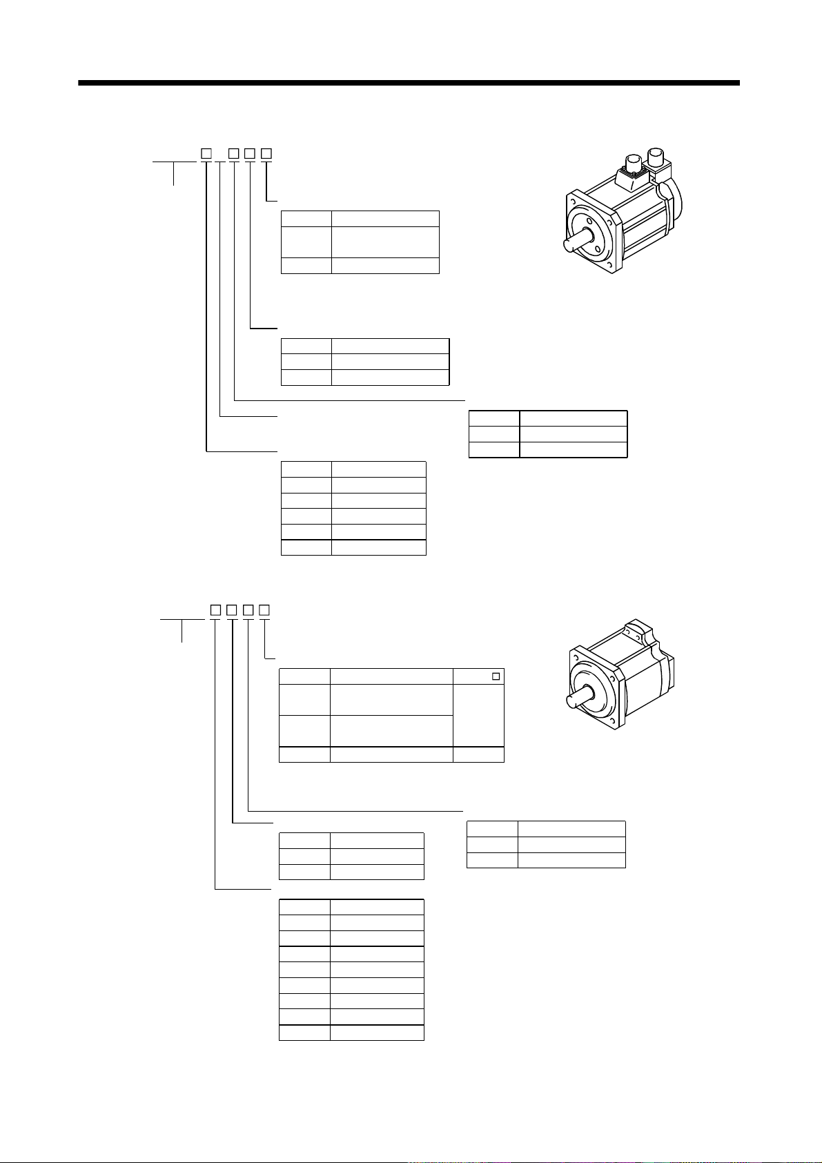
(d) HC-RF series (ultra low inertia, middle capacity)
Series name
3 HC-RF
Appearance
Shaft type
Symbol
None
(Note) K
Note. The special shaft applies to the
standard servo motor and servo
motor with electromagnetic brake.
Shaft Shape
Standard
(Straight shaft)
With keyway (With key)
Reduction gear
Symbol
None Without
G2
Reduction Gear
For precision application
Electromagnetic brake
Rated speed
3000 [r/min]
Rated output
Symbol
10
15 1.5
20
35 3.5
50
Rated Output [kW]
1
2
5
Symbol
None
B
Electromagnetic Brake
Without
With
(e) HC-UF series (flat type, small and middle capacity)
HC-UF
Series name
Shaft type
Symbol
None
(Note) K
(Note) D
Note. The special shaft applies to the standard
servo motor and servo motor with
electromagnetic brake.
Shaft Shape
Standard
(Straight shaft)
With keyway
(HC-UF23 to 73: With key)
D-cut shaft
Rated speed
Speed [r/min]Symbol
2
3
2000
3000
Rated output
1
2
4
7
15
20
35
Rated Output [kW]
0.1
0.2
0.4
0.75
1.5
2
3.5
550
Symbol
Appearance
HC-UF
13 to 43
72 to 202
13
Electromagnetic brake
Symbol
None
Electromagnetic Brake
B
Without
With
1 - 5
Page 21
1. INTRODUCTION
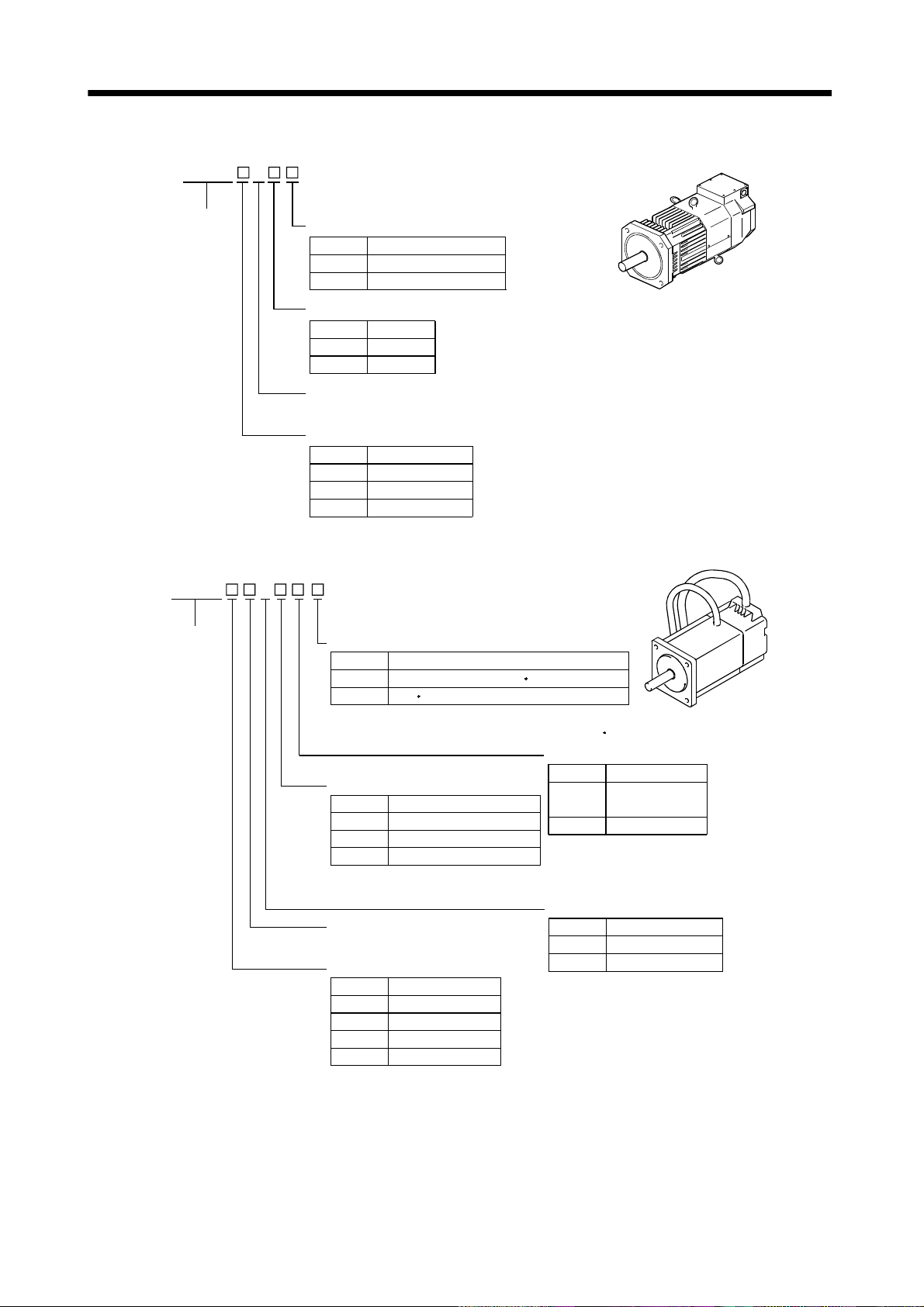
(f) HA-LH series (low inertia, large capacity)
HA-LH
Series name
2
Compliant Standard
Symbol
None
-EC
Specifications
Standard model (in Japan)
EN Standard
Encoder
Symbol
None
-Y
Encoder
Incremental
Absolute
Rated speed
2000[r/min]
Rated output
Rated Output [kW]Symbol
11K
15K
22K
11
15
22
(g) HC-KF series (low inertia, small capacity)
HC-KF 3
Appearance
Appearance
Series name
Compliance with Standard
Symbol Specifications
None (Note) Standard model (EN UL/C-UL Standard)
-UE
EN UL/C-UL Standard
Note. The standard models produced in and after
February, 2001 are compatible with the EN UL/C-UL Standard.
Shaft type
Reduction gear
Symbol Reduction Gear
None
G1 For general industrial machine
G2 For precision application
Without
Symbol
None
(Note) K With keyway
Note. The special shaft applies
Shaft Shape
Standard
(Straight shaft)
to the standard servo motor
and servo motor with
electromagnetic brake.
Electromagnetic brake
Rated speed
3000[r/min]
Rated output
Symbol Rated Output [kW]
05 0.05
0.11
20.2
0.44
Symbol Electromagnetic Brake
None
BWith
Without
1 - 6
Page 22
1. INTRODUCTION
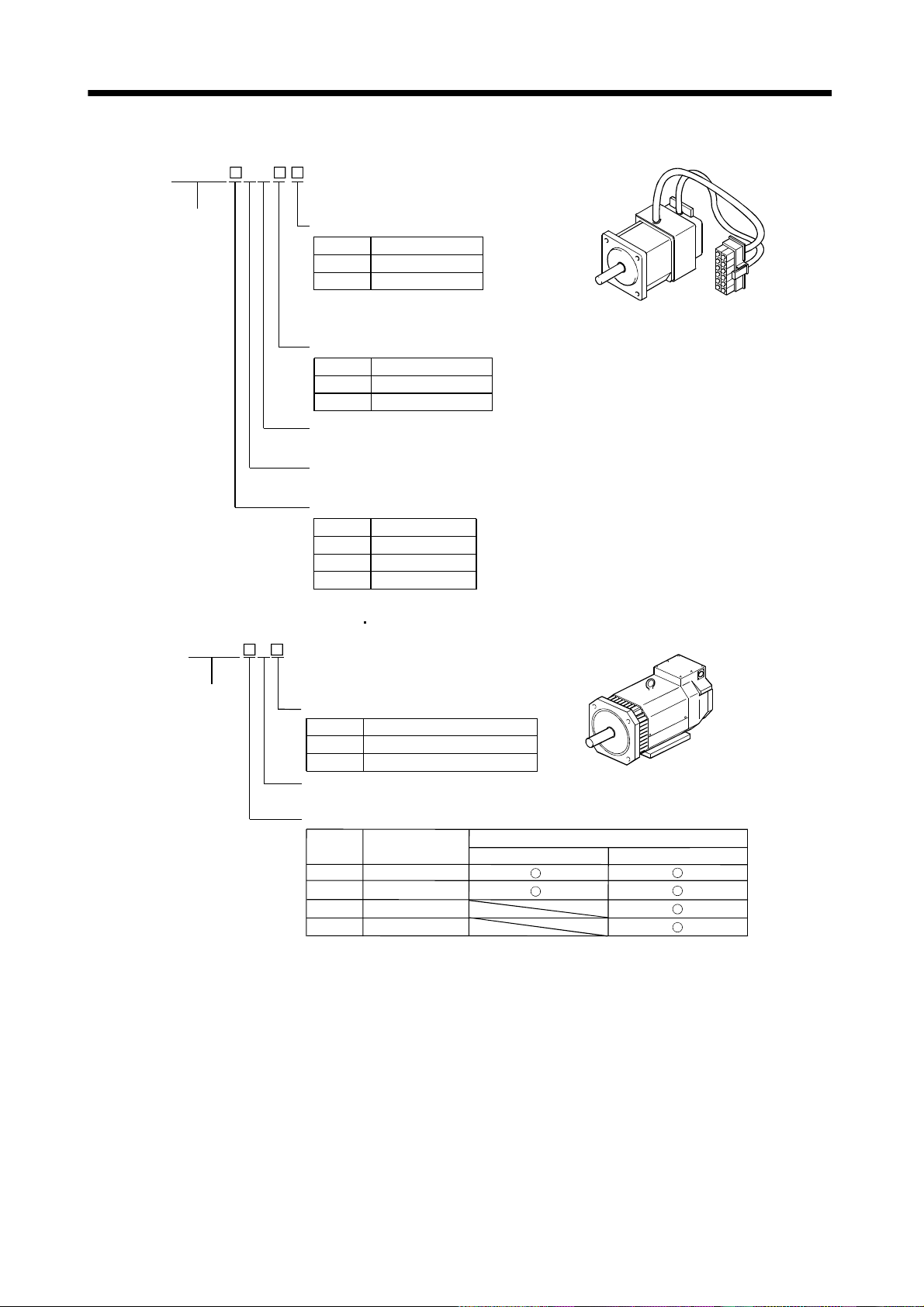
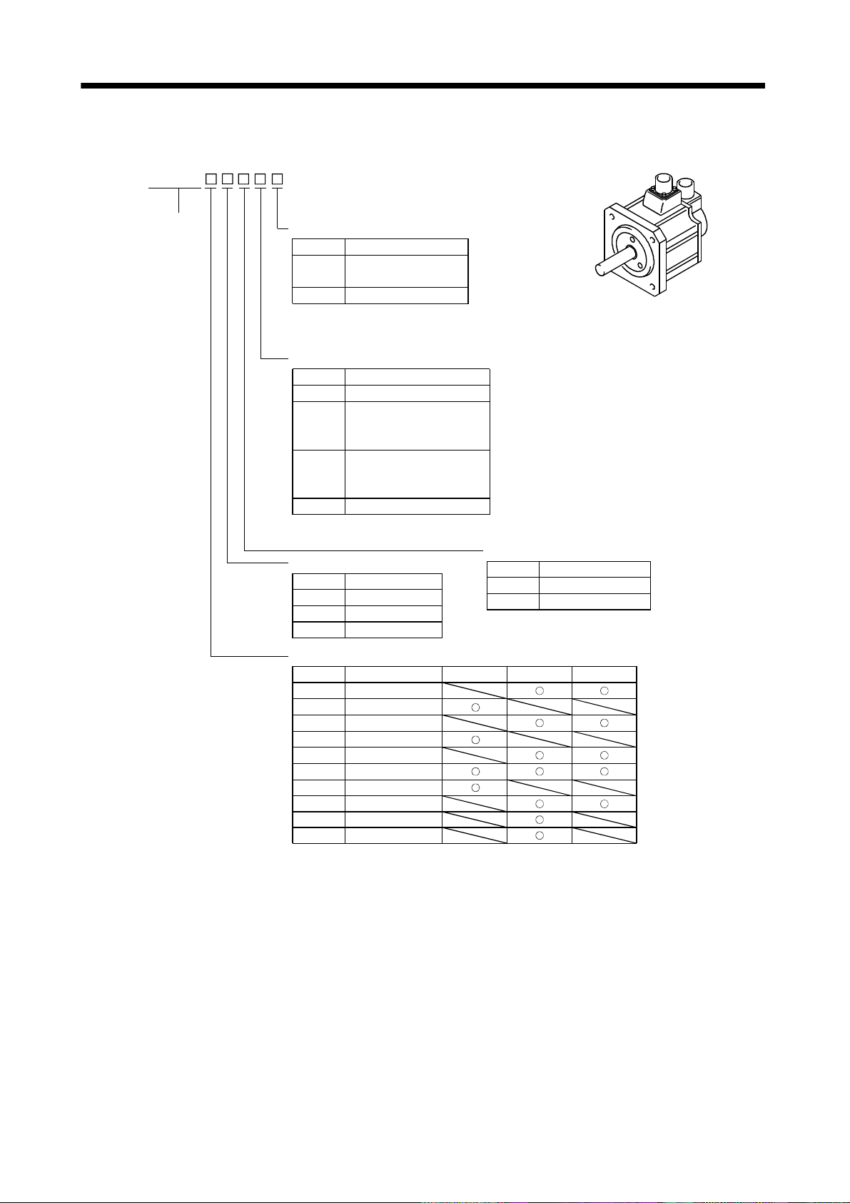
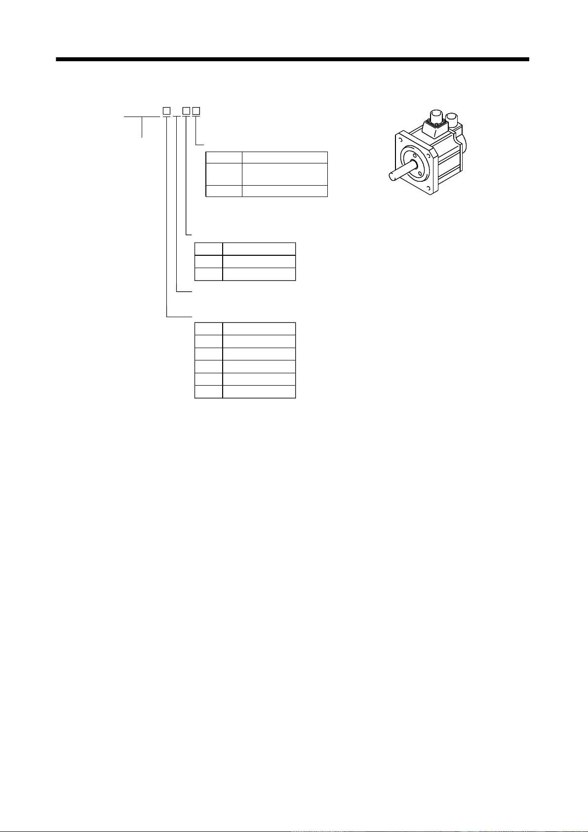
(h) HC-AQ series (24VDC-compatible, compact size, small capacity)
HC-AQ
Series name
35
Shaft type
Symbol
(Note) D D-cut shaft
(Note) S Straight shaft
Note. The special shaft applies to
the standard servo motor and
servo motor with electromagnetic brake.
Shaft Shape
Electromagnetic brake
Symbol
None
Electromagnetic Brake
B
Without
With
Power supply voltage
24VDC
Rated speed
3000 [r/min]
Rated output
Rated Output [kW]Symbol
01
02
03
0.01
0.02
0.03
Appearance
(i) HA-LF series (Three-phase, 200 400VAC-compatible, low inertia, large capacity)
HA-LF
Series name
2
Appearance
Power supply specification
Power Supply VoltageSymbol
None
Three-phase 200 to 230VAC
4
Three-phase 380 to 480VAC
Rated speed
2000 [r/min]
Rated output
Symbol
30K
37K
45K
55K
Rated Output [kW]
30
37
45
55
Three-phase 200 to 230VAC
Power supply specifications
Three-phase 380 to 480VAC
1 - 7
Page 23
1. INTRODUCTION
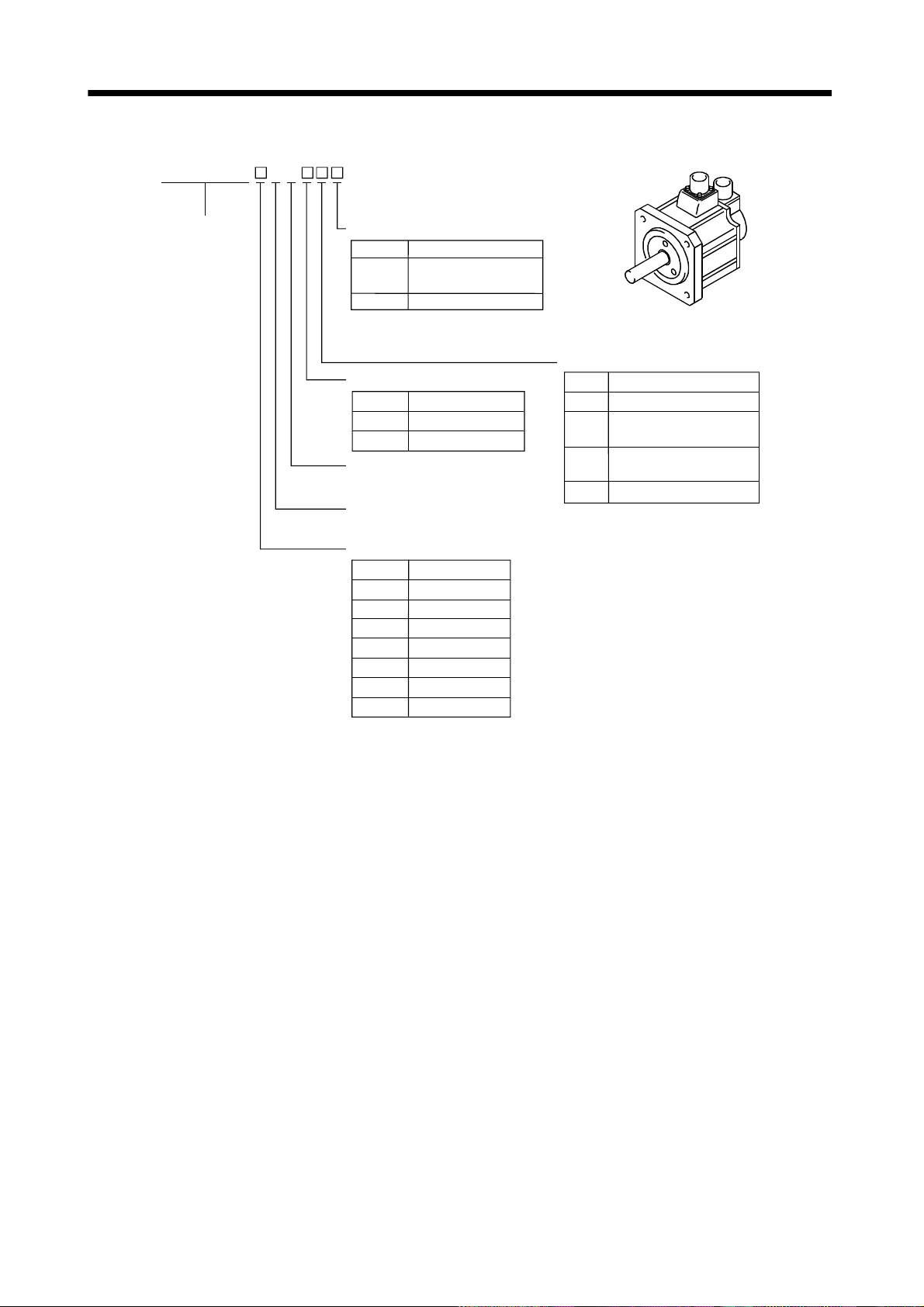
(j) HC-KFS series (low inertia, small capacity, high resolution)
HC-KFS
Series name
3
Appearance
Shaft type
Reduction gear
Symbol
None
G1 For general industrial machine
G2 For precision application
Reduction Gear
Without
Symbol
None
(Note) K
(Note) D
Note. The special shaft applies to the standard
servo motor and servo motor with
electromagnetic brake.
Shaft Shape
Standard
(Straight shaft)
With keyway (With key)
D-cut shaft
HC-KFS
053 to 73
23 to 73
053 13
Electromagnetic brake
Rated speed
3000[r/min]
Rated output
Symbol Rated Output [kW]
05 0.05
0.11
20.2
0.44
Symbol Electromagnetic Brake
None Without
BWith
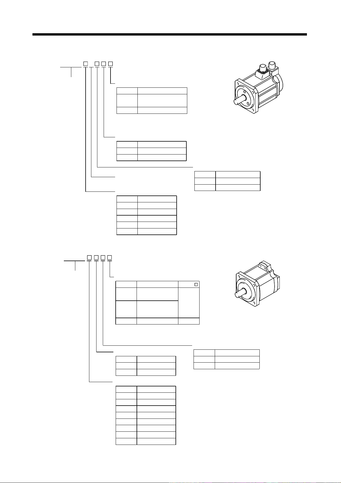
(k) HC-MFS series (ultra low inertia, small capacity, high resolution)
HC-MFS
Series name
3
Reduction gear
Symbol
None Without
G1
G2
Reduction Gear
For general
industrial machine
For precision application
Rated speed
3000 [r/min]
Rated output
Symbol
Rated Output [kW]
05
1
2
4
7 0.75
Appearance
Shaft type
Symbol
None
(Note) K
(Note) D
Note. The special shaft applies to the standard
servo motor and servo motor with
electromagnetic brake.
Electromagnetic brake
Symbol
None
B
0.05
0.1
0.2
0.4
Shaft Shape
Standard
(Straight shaft)
With keyway (With key)
D-cut shaft
Electromagnetic Brake
Without
With
HC-MFS
053 to 73
23 to 73
53 13
1 - 8
Page 24
1. INTRODUCTION
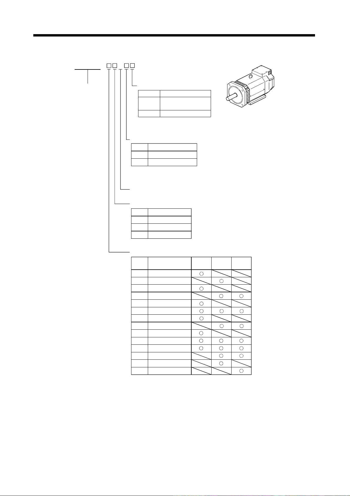
(l) HC-SFS series (middle inertia, middle capacity, high resolution)
1) 200VAC-compatible
HC-SFS
Series name
Shaft type
Symbol
None
(Note) K
Note. The special shaft applies to the
standard servo motor and servo
motor with electromagnetic brake.
Shaft Shape
Standard
(Straight shaft)
With keyway (Without key)
Reduction gear
Symbol
None Without
G1
G1H
G2
Note. Not provided for 1000r/min and
3000r/min series.
Reduction Gear
(Note) For general
industrial machine
(flange type)
(Note) For general
industrial machine
(leg type)
(Note) For precision application
Rated speed
Symbol
1
2
3
Speed [r/min]
1000
2000
3000
Appearance
Electromagnetic brake
Symbol
None
Electromagnetic Brake
B
Without
With
Rated output
Symbol
5
8
10
12
15
20
30
35
50 5
70
Rated Output [kW]
0.5
0.85
1
1.2
1.5
2
3
3.5
7
1000 [r/min]
2000 [r/min]
3000 [r/min]
1 - 9
Page 25
1. INTRODUCTION
2) 400VAC-compatible
HC-SFS 2 4
Series name
Shaft type
Symbol
None
(Note) K
Note. The special shaft applies to the
standard servo motor and servo
motor with electromagnetic brake.
Shaft Shape
Standard
(Straight shaft)
With keyway (Without key)
Electromagnetic brake
Symbol
Electromagnetic brake
None
B
Without
With
Power supply voltage
Three-phase 380 to 480 VAC
Rated speed
2000 [r/min]
Rated output
5
10
15
20
35
50
70
Rated output [kW]
0.5
1
1.5
2
3.5
5
7
Symbol
Appearance
Reductiongear
Symbol Reductiongear
None
For general industrial machine
G1
For general industrial machine
G1H
G2
Without
(flange type)
(leg type)
For precision application
1 - 10
Page 26
1. INTRODUCTION
(m) HC-RFS series (ultra low inertia, middle capacity, high resolution)
Series name
3 HC-RFS
Appearance
Shaft type
Symbol
None
(Note) K
Note. The special shaft applies to the
standard servo motor and servo
motor with electromagnetic brake.
Shaft Shape
Standard
(Straight shaft)
With keyway (Without key)
Reduction gear
Symbol
None Without
G2
Reduction Gear
For precision application
Electromagnetic brake
Rated speed
3000 [r/min]
Rated output
Symbol
10
15
20
35
50
Symbol
None
Rated Output [kW]
1
1.5
2
3.5
5
Electromagnetic Brake
B
Without
With
(n) HC-UFS series (flat type small and middle capacity, high resolution)
HC-UFS
Series name
Shaft type
Symbol
None
(Note) K
(Note) D
Note. The special shaft applies to the standard
servo motor and servo motor with
electromagnetic brake.
Shaft Shape
Standard
(Straight shaft)
With keyway
HC-UFS 23 to 73 are
provided with keys.
D-cut shaft
HC-UFS
13 to 43
72 to 202
13
Electromagnetic brake
Rated speed
Speed [r/min]Symbol
2
3
2000
3000
Rated output
1
2
4
7
15
20
Rated Output [kW]
0.1
0.2
0.4
0.75
1.5
2
3.535
550
Symbol
Symbol
Appearance
Electromagnetic Brake
None
B
Without
With
1 - 11
Page 27
1. INTRODUCTION
(o) HA-LFS series (low inertia, middle large capacity, high resolution)
1) 200VAC-compatible
HA-LFS
Appearance
Series name
Shaft type
Symbol
None
(Note) K
Note. The special shaft applies to the
standard servo motor and servo
motor with electromagnetic brake.
Shaft Shape
Standard
(Straight shaft)
With keyway (Without key)
Electromagnetic brake
Symbol
Electromagnetic brake
Note
(Note)B
Note. Refer to Table 6.1 for the servo motor
compatible with the electromagnetic brake.
Without
For precision application
Rated speed
Symbol
1
1M
2
Speed [r/min]
1000
1500
2000
Rated output
Symbol
Rated Output [kW]
50 5
60 6
70 7
80 8
11K 11
12K 12
15K 15
20K 20
22K 22
25K 25
30K 30
37K 37
1000
[r/min]
1500
[r/min]
2000
[r/min]
1 - 12
Page 28
1. INTRODUCTION
2) 400VAC-compatible
HA-LFS
Series name
4
Shaft type
Symbol
None
(Note) K
Note. The special shaft applies to the
standard servo motor and servo
motor with electromagnetic brake.
Shaft Shape
Standard
(Straight shaft)
With keyway (Without key)
Electromagnetic brake
Symbol
Electromagnetic brake
Note
(Note)B
Without
For precision application
Note. Refer to Table 6.1 for the servo motor
compatible with the electromagnetic brake.
Power supply voltage
Three-phase 380 to 480 VAC
Rated speed
Symbol
1
1M
22000
Speed [r/min]
1000
1500
Appearance
Rated output
Symbol
Rated Output [kW]
60 6
70 7
80 8
11K 11
12K 12
15K 15
20K 20
22K 22
25K 25
30K 30
37K 37
45K 45
50K 50
55K 55
1000
[r/min]
1500
[r/min]
2000
[r/min]
1 - 13
Page 29
1. INTRODUCTION
(p) HC-LFS series (low inertia, middle capacity, high resolution)
HC-LFS
Series name
2
Shaft type
Symbol
None
(Note) K
Note. The special shaft applies to the
Electromagnetic brake
Symbol
None
B
Rated speed
2000 [r/min]
Rated output
Symbol
5
10 1
15
20 2
30
Appearance
Shaft Shape
Standard
(Straight shaft)
With keyway (Without key)
standard servo motor and servo
motor with electromagnetic brake.
Electromagnetic Brake
Without
With
Rated Output [kW]
0.5
1.5
3
1 - 14
Page 30
1. INTRODUCTION
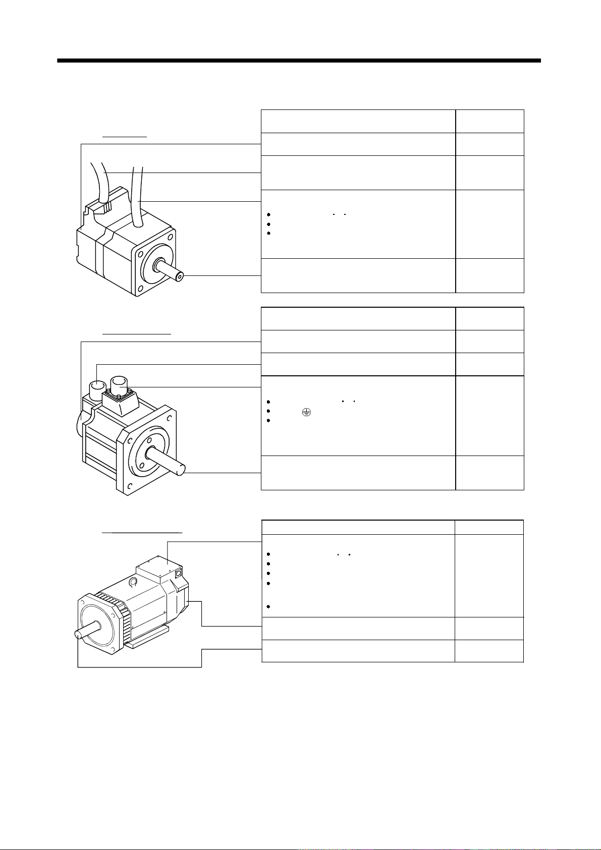
1.3 Parts identification
Lead type
Connector type
Name/Application
Encoder Section 5.1
Encoder cable
with encoder connector
Power cable
Power lead (U V W)
Earth lead
Brake lead
(for motor with electromagnetic brake)
Servo motor shaft
Name/Application
Encoder
Encoder connector
Power connector
Power supply (U V W)
Earth ( )
Brake (for motor with electromagnetic brake)
Some motors with electromagnetic brakes
have brake connectors separately.
Reference
Section 3.2
Chapter 7
Chapter 2
Section 5.4
Reference
Section 5.1
Section 3.2
Chapter 7
Terminal box type
Servo motor shaft
Name/Application Reference
Terminal box
Power leads (U V W)
Cooling fan leads
Ground terminal
Brake lead
(for motor with electromagnetic brake)
Encoder connector
Encoder
Servo motor shaft
Chapter 2
Section 5.4
Chapter 7
Section 3.2
Section 5.1
Chapter 2
1 - 15
Page 31

1. INTRODUCTION
MEMO
1 - 16
Page 32

2. INSTALLATION
2. INSTALLATION
CAUTION
Stacking in excess of the limited number of products is not allowed.
Install the equipment on incombustible material. Installing them directly or close to
combustibles will lead to a fire.
Install the equipment in a load-bearing place in accordance with this Instruction
Manual.
Do not get on or put heavy load on the equipment to prevent injury.
Use the equipment within the specified environmental condition range.
Do not subject the servo motor to drop impact or shock loads as they are precision
equipment.
Do not install or operate a faulty servo amplifier.
Do not hold the cable, shaft or encoder to carry the servo motor. Otherwise, a fault
or injury may occur.
The lifting eyebolts of the servo motor may only be used to transport the servo
motor. They must not be used to transport the servo motor when it is mounted on a
machine.
The servo motor with reduction gear must be installed in the specified direction.
Otherwise, it can leak oil, leading to a fire or fault.
Securely fix the servo motor to the machine. If fixed insecurely, the servo motor will
come off during operation, leading to injury.
When coupling the shaft end of the servo motor, do not subject the shaft end to
impact, such as hammering. The encoder may become faulty.
When coupling a load to the servo motor, do not use a rigid coupling. Doing so can
cause the shaft to break.
Take safety measures, e.g. provide covers, to prevent accidental access to the
rotating parts of the servo motor during operation.
Do not subject the servo motor shaft to more than the permissible load. Otherwise,
the shaft may break, leading to injury.
When the product has been stored for an extended period of time, consult
Mitsubishi.
When treating the servo motor, be careful about the edged parts such as the
corners of the servo motor.
2 - 1
Page 33

2. INSTALLATION
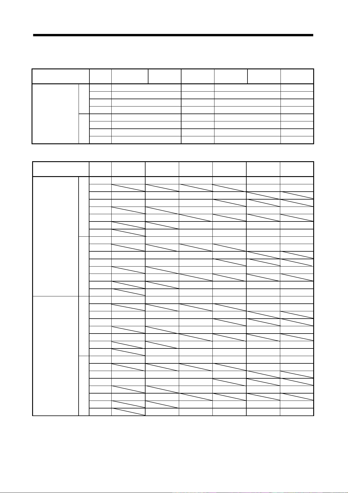
2.1 Environmental conditions
Environment Conditions
Ambient
temperature
Ambient
humidity
Ambience
Altitude Max. 1000m (3280 ft) above sea level
(Note) Vibration
In Operation
In Storage
In Operation 80%RH or less (non-condensing)
In Storage 90%RH or less (non-condensing)
Note. Except the servo motor with reduction gear.
[ ]0 to 40 (non-freezing)
] 32 to 104 (non-freezing)
[
[ ] 15 to 70 (non-freezing)
[
] 5 to 158 (non-freezing)
Indoors (no direct sunlight)
Free from corrosive gas, flammable gas, oil mist, dust and dirt
HC-KFS series
HC-MFS series
HC-SFS81
HC-SFS52 to 152
HC-SFS53 to 153
HC-SFS121 201
HC-SFS202
HC-SFS203
HC-SFS301
HC-SFS502
HC-AQ series
HC-KF series
HC-MF series
HC-SF81
[m/s2]
[ft/s
2
]
HC-SF52 to 152
HC-SF53 to 153
HC-SF121 201
HC-SF202
HC-SF203
HA-LFS601 to12K1
HA-LFS701M to 15K1M
HA-LFS502 to 22K2
HA-LFS6014 to 12K14
HA-LFS701M4 to 15K1M4
HA-LFS11K24 to 22K24
HA-LFS15K1 to 37K1
HA-LFS22K1M to 37K1M
HA-LFS30K2
HA-LFS15K14 to 37K14
HA-LFS22K1M4 to 50K1M4
HA-LFS30K24 to 55K24
HC-KFS series
HC-MFS series
HC-SFS81
HC-SFS52 to 152
HC-SFS53 to 153
HC-SFS121 201
HC-SFS202
HC-SFS203
HC-SFS301
HC-SFS502
HC-AQ series
HC-KF series
HC-MF series
HC-SF81
HC-SF52 to 152
HC-SF53 to 153
HC-SF121 201
HC-SF202
HC-SF203
HA-LFS601 to12K1
HA-LFS701M to 15K1M
HA-LFS502 to 22K2
HA-LFS6014 to 12K14
HA-LFS701M4 to 15K1M4
HA-LFS11K24 to 22K24
HA-LFS15K1 to 37K1
HA-LFS22K1M to 37K1M
HA-LFS30K2
HA-LFS15K14 to 37K14
HA-LFS22K1M4 to 50K1M4
HA-LFS30K24 to 55K24
352
353
352
353
352
353
702
352
353
702
37K2
37K2
HC-UFS13 to 73 X,Y:49
HC-SFS524 to 1524
HC-RFS series
HC-UFS72
HC-SFS2024
HC-UFS202 to 502
HC-SFS5024
HA-FF series
HC-UF13 to 73
HC-RF series
HC-UF72
HC-LFS52 to152
HC-UF202 to 502
HC-LFS202
HA-LH11K2 to 22K2
HC-SF301
HC-SF502
HA-LF series X,Y:9.8
HC-UFS13 to 73 X,Y:161
HC-SFS524 to 1524
HC-RFS series
HC-UFS72
HC-SFS2024
HC-UFS202 to 502
HC-SFS5024
HA-FF series
HC-UF13 to 73
HC-RF series
HC-UF72
HC-LFS52 to152
HC-UF202 to 502
HC-LFS202
HA-LH11K2 to 22K2
HC-SF301
HC-SF502
HA-LF series X,Y:32
152
702
152
702
152
302
152
302
3524
7024
3524
7024
X,Y:24.5
X:24.5
Y:49
X:24.5
Y:29.4
X,Y:19.6
X:9.8
Y:24.5
X:19.6
Y:49
X:11.7
Y:29.4
X,Y:80
X:80
Y:161
X:80
Y:96
X,Y:64
X:32
Y:80
X:64
Y:161
X:38.4
Y:96.5
2 - 2
Page 34

2. INSTALLATION
a
r
Vibration occurs in the directions shown below.
The values were measured at the portion which
indicates the maximum value (normally the bracket
opposite to load side). When the servo motor is at
stop, the bearings are likely to fret and vibration
should therefore be suppressed to about half of the
permissible value.
Servo moto
X
Vibration
Y
Graph of vibration servo amplitude vs. speed
]
200
m
[
)
s
e
d
u
100
t
i
l
p
80
m
a
60
h
t
o
50
b
(
40
e
d
u
t
30
i
l
p
m
a
20
n
o
i
t
a
r
b
i
V
500 1000 15002000 250030003500
Speed [r/min]
2 - 3
Page 35
2. INSTALLATION
2.2 Installation orientation
The following table lists directions of installation.
Servo Motor Series Direction of Installation Remarks
HC-KF
HA-FF
HC-RF
HC-KFS
HC-SFS
HC-UFS
HA-LFS (Flange type)
HA-LFS (Flange
When the servo motor with electromagnetic brake is installed with the shaft end at top, the brake plate
may generate sliding sound but it is not a fault. Refer to section 5.3 for the installation orientation of the
servo motor with reduction gear.
2.3 Load remove precautions
HC-MF
HC-SF
HC-UF
HC-MFS
HC-RFS
HC-LFS
HC-AQ
HA-LH
HA-LF
leg type)
May be installed in any
direction.
Horizontal direction with
the legs downward.
For installation in the horizontal direction, it is recommended to set the
connector section downward.
Use either the legs or flange for installation.
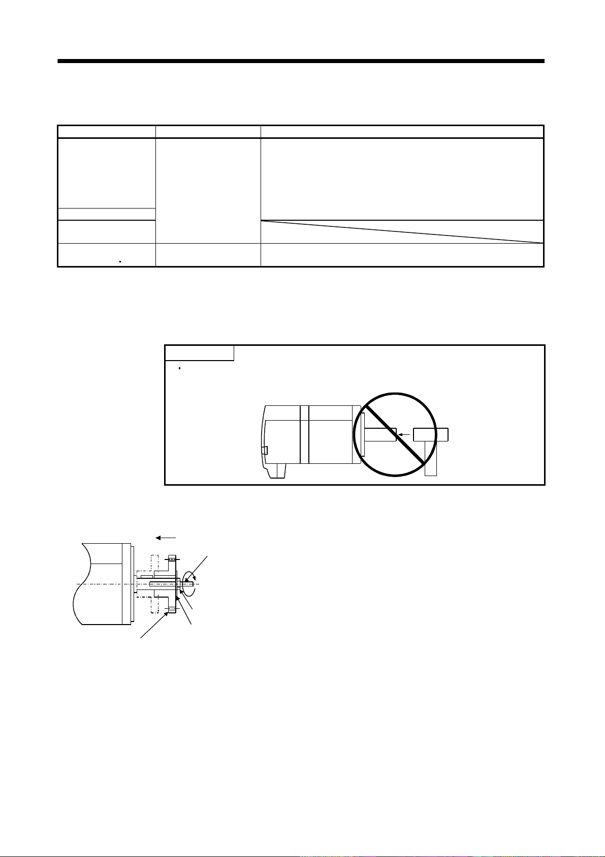
POINT
During assembling, the shaft end must not be hammered. Doing so can
cause the encoder to fail.
(1) When mounting a pulley to the servo motor shaft provided with a keyway, use the screw hole in the
shaft end. To fit the pulley, first insert a double-end stud into the screw hole of the shaft, put a washer
against the end face of the coupling, and insert and tighten a nut to force the pulley in.
Servo motor
Double-end stud
Nut
Washer
Pulley
(2) For the servo motor shaft with a keyway, use the screw hole in the shaft end. For the shaft without a
keyway, use a friction coupling or the like.
(3) When removing the pulley, use a pulley remover to protect the shaft from impact.
(4) To ensure safety, fit a protective cover or the like on the rotary area, such as the pulley, mounted to
the shaft.
(5) When a threaded shaft end part is needed to mount a pulley on the shaft, please contact us.
(6) The orientation of the encoder on the servo motor cannot be changed.
(7) For installation of the servo motor, use spring washers, etc. and fully tighten the bolts so that they do
not become loose due to vibration.
(8) For the HC-AQ series, use spring washers and apply Screw Lock to mount the servo motor. In
addition, use Helisert screws when the flange for mouthing the servo motor is made of aluminum.
2 - 4
Page 36

2. INSTALLATION
2.4 Permissible load for the shaft
POINT
Do not use a rigid coupling as it may apply excessive bending load to the
shaft, leading to shaft breakage.
(1) Use a flexible coupling and make sure that the misalignment of the shaft is less than the permissible
radial load.
(2) When using a pulley, sprocket or timing belt, select a diameter that will fit into the permissible radial
load.
(3) Excess of the permissible load can cause the bearing life to reduce and the shaft to break.
(4) The load indicated in this section is static load in a single direction and does not include eccentric load.
Make eccentric load as small as possible. Not doing so can cause the servo motor to be damaged.
2.4.1 Without reduction gear
HC-KF
HC-KFS
HC-MF
HC-MFS
HA-FF
HC-SF
HC-SFS
HC-LFS
HC-RF
HC-RFS
HC-UF
HC-UFS
HA-LH
HA-LF
HA-LFS
Servo Motor
053 / 13 25 0.98 88 20 59 13
23 / 43 30 1.18 245 55 98 22
73 (Note 3) 40 1.57 392 88 147 33
053 / 13 25 0.98 88 20 59 13
23 / 43 30 1.18 245 55 98 22
73 40 1.57 392 88 147 33
053 30 1.18 108 24 98 22
13 30 1.18 118 27 98 22
23 / 33 30 1.18 176 40 147 33
43 / 63 40 1.57 323 73 284 64
81 55 2.17 980 220 490 110
121 to 301 79 3.11 2058 463 980 220
52 (4) to 152 (4) (Note4) 55 2.17 980 220 490 110
202 (4) / 702 (4) (Note4) 79 3.11 2058 463 980 220
53 to 153 55 2.17 980 220 490 110
203 / 353 79 3.11 2058 463 980 220
52 to 152 55 2.17 980 220 490 110
202/302 79 3.11 2058 463 980 220
103 to 203 45 1.77 686 154 196 44
353 / 503 63 2.48 980 220 392 88
72 / 152 55 2.17 637 143 490 110
202 65 2.56 882 198 784 176
352 / 502 65 2.56 1176 264 784 176
13 25 0.98 88 20 59 13
23 / 43 30 1.18 245 55 98 22
73 40 1.57 392 88 147 33
11K2 85 3.35 2450 551 980 220
15K2 / 22K2 110 4.33 2940 661 980 220
0135 16 0.63 34 8 14 3
0235 16 0.63 44 10 14 3HC-AQ
0335 16 0.63 49 11 14 3
30K2(4) 37K2(4) 140 5.51 3234 727 1470 330
45K24 /55K24 140 5.51 4900 1102 1960 441
502/702/601(4)/701M(4)/11K2(4) 85 3.35 2450 551 980 153
801(4) 12K1(4) 11K1M(4)
15K1M(4) 15K2(4) 22K2(4)
15K1(4) 20K1(4) 22K1M(4)
30K1M(4) 30K2(4) 37K2(4)
25K1(4) 30K1(4) 37K1M(4)
45K1M4 45K24•55K24
37K1(4)
50K1M4 170 6.69 6370 1432 1960 441
L (Note 1)
[mm] [in] [N] [lb] [N] [lb]
110 4.33 2940 661 980 153
140 5.51 3234 727 1470 330
140 5.51 4900 1102 1960 441
Permissible Radial Load
(Note 2)
Permissible Thrust Load
(Note 2)
2 - 5
Page 37

2. INSTALLATION
Note 1. For the symbols in the table, refer to the following diagram.
L
Radial load
Thrust load
2. Do not subject the shaft to load greater than this value. The values in the table assume that the loads work singly.
3. 73 is not available for the HC-KF series.
4. 524 to 7024 are not available for the HC-SF series.
L: Distance from flange mounting surface to load center
2 - 6
Page 38

2. INSTALLATION
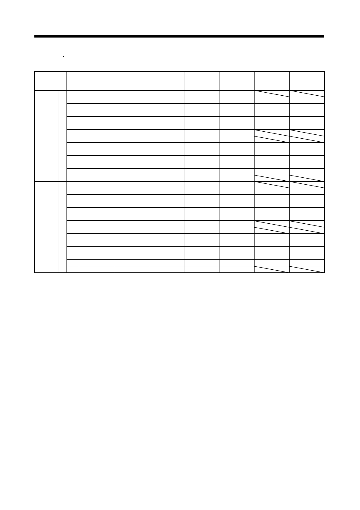
2.4.2 With reduction gear
The permissible radial loads in the table are the values at the center of the reduction gear output shaft.
Q/ 2
Q
(1) HC-MF HC-MFS HC-KF HC-KFS series
(a) General industrial machine-compliant
Item
Permissible
Radial Load
Permissible
Thrust Load
HC-MF053(B)G1
HC-MFS053(B)G1
Gear
ratio
1/12 240 710 620[N]
1/20 370 780 760 970
[lb]
1/12 54 160 139
1/20 83 175 171 218
1/12 320 720 620[N]
1/20 450 780 760 960
[lb]
1/12 72 162 139
1/20 101 175 171 216
HC-KF053(B)G1
HC-KFS053(B)G1
1/5 150 330 430
1/5 34 74 97
1/5 200 350 430
1/5 45 79 97
HC-MF13(B)G1
HC-MFS13(B)G1
HC-KF13(B)G1
HC-KFS13(B)G1
HC-MF23(B)G1
HC-MFS23(B)G1
HC-KF23(B)G1
HC-KFS23(B)G1
HC-MF43(B)G1
HC-MFS43(B)G1
HC-KF43(B)G1
HC-KFS43(B)G1
HC-MF73(B)G1
HC-MFS73(B)G1
HC-KFS73(B)G1
(b) Precision application-compliant
HC-MF053(B)G2
Item
Permissible
Radial Load
Permissible
Thrust Load
Gear
[N]
[lb]
[N]
[lb]
HC-MFS053(B)G2
ratio
1/20 260 540 610 790 1040
1/29 290 610 700 900 1190
1/20 58 121 137 178 234
1/29 65 137 157 202 268
1/20 400 660 640 790 1140
1/29 450 750 830 1010 1290
1/20 90 148 144 178 256
1/29 101 167 187 227 290
HC-KF053(B)G2
HC-KFS053(B)G2
1/5 160 160 160 340 390
1/9 200 200 420 480 600
1/53636367688
1/9 45 45 94 108 135
1/5 220 220 220 370 390
1/9 270 270 450 490 600
1/54949498387
1/9 61 61 101 110 135
HC-MF13(B)G2
HC-MFS13(B)G2
HC-KF13(B)G2
HC-KFS13(B)G2
HC-MF23(B)G2
HC-MFS23(B)G2
HC-KF23(B)G2
HC-KFS23(B)G2
HC-MF43(B)G2
HC-MFS43(B)G2
HC-KF43(B)G2
HC-KFS43(B)G2
HC-MF73(B)G2
HC-MFS73(B)G2
HC-KFS73(B)G2
2 - 7
Page 39
2. INSTALLATION
(2) HA-FF series
(a) General industrial machine-compliant
Gear
Item
[N]
Permissible Radial
Load
[lb]
(b) Precision application-compliant
Item
Permissible Radial
Load
Permissible Thrust
Load
Gear
[N]
[lb]
[N]
[lb]
HA-FF053(B)G1 HA-FF13(B)G1 HA-FF23(B)G1 HA-FF33(B)G1 HA-FF43(B)G1 HA-FF63(B)G1
ratio
1/5 588 686 686 980
1/10 588 686 686 1470
1/20 588 1176 1568 1764
1/30 686 1225 1764 2156
1/5 132 154 154 220
1/10 132 154 154 330
1/20 132 264 353 397
1/30 154 275 397 485
HA-FF053(B)G2 HA-FF13(B)G2 HA-FF23(B)G2 HA-FF33(B)G2 HA-FF43(B)G2 HA-FF63(B)G2
ratio
1/5 69 69 98 216 216 588
1/9 735 735
1/10 88 127 265 265
1/15 137 216 392
1/20 980 980 1274 1274
1/25 392 784
1/29 1078 1470 1470 1470
1/45 1274 1666 1666 1666 3430
1/51515224949132
1/9 165 165
1/10 20 29 60 60
1/15 31 49 88
1/20 220 220 286 286
1/25 88 176
1/29 242 330 330 330
1/45 286 375 375 375 771
1/5 59 59 147 265 265 784
1/9 980 980
1/10 78 167 343 343
1/15 88 216 363
1/20 1372 1372 2254 2254
1/25 314 412
1/29 1764 2548 2548 2548
1/45 1960 3234 3234 3234 5390
1/51313336060176
1/9 220 220
1/10 16 38 77 77
1/15 20 49 82
1/20 308 308 507 507
1/25 71 93
1/29 397 573 573 573
1/45 441 727 727 727 1212
2 - 8
Page 40
2. INSTALLATION
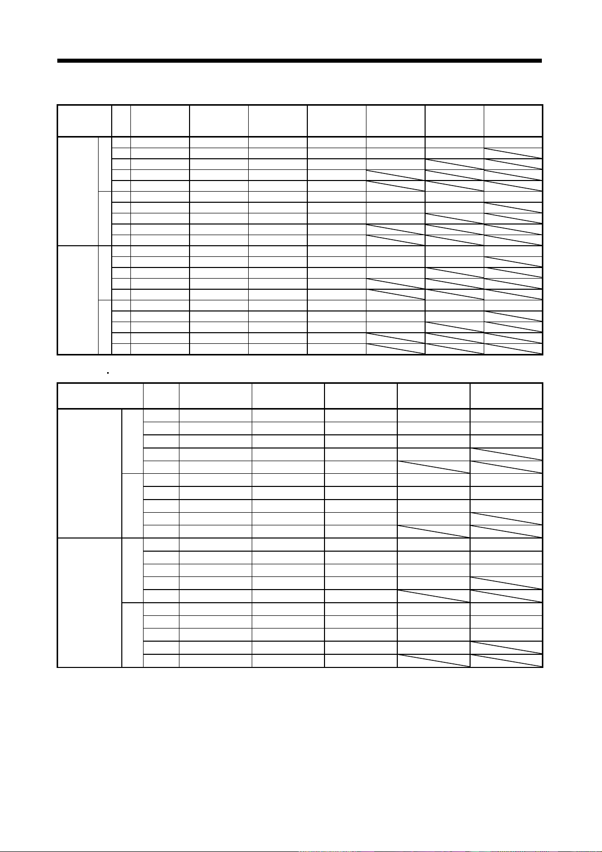
(3) HC-SF HC-SFS (2000r/min) series
(a) General industrial machine-compliant
Item
Permissible
Radial Load
Permissible
Thrust
Load
HC-SF52(B)G1
Gear
HC-SFS52(B)G1
ratio
HC-SFS524(B)G1
1/6 2058 2842 2842 2842 3332
1/11 2391 3273 3273 3273 3871 5488 7526
1/17 2832 3646 3646 3646 4420 6468 8683
1/29 3273 4410 5135 7291 7291 13426 13426
[N]
1/35 5253 5253 6047 8555 8555 16072 16072
1/43 5253 6047 8555 8555 11662 16072 22540
1/59 5880 9741 9741 9741 13132
1/6 463 639 639 639 749
1/11 538 728 728 728 870 1234 1952
1/17 637 820 820 820 994 1454 1952
1/29 728 991 1154 1639 1639 3018 3018
[lb]
1/35 1181 1181 1359 1923 1923 3613 3613
1/43 1181 1359 1923 1923 2622 3613 5067
1/59 1322 2190 2190 2190 2952
1/6 1470 2352 2352 2352 3920
1/11 1470 2764 2764 2764 3920 6292 8085
1/17 1470 2940 2940 2940 3920 6860 9673
1/29 1470 2940 3920 6860 6860 13720 13720
[N]
1/35 2940 2940 3920 6860 6860 13720 13720
1/43 2940 3920 6860 6860 9800 13720 19600
1/59 2940 6860 6860 6860 9800
1/6 330 529 529 529 881
1/11 330 621 621 621 881 1415 1818
1/17 330 661 661 661 881 1542 2175
1/29 330 661 881 1542 1542 3084 3084
[lb]
1/35 661 661 881 1542 1542 3084 3084
1/43 661 881 1542 1542 2203 3084 4406
1/59 661 1542 1542 1542 2203
HC-SF102(B)G1
HC-SFS102(B)G1
HC-SFS1024(B)G1
HC-SF152(B)G1
HC-SFS152(B)G1
HC-SFS1524(B)G1
HC-SF202(B)G1
HC-SFS202(B)G1
HC-SFS2024(B)G1
HC-SF352(B)G1
HC-SFS352(B)G1
HC-SFS3524(B)G1
HC-SF502(B)G1
HC-SFS502(B)G1
HC-SFS5024(B)G1
HC-SF702(B)G1
HC-SFS702(B)G1
HC-SFS7024(B)G1
2 - 9
Page 41
2. INSTALLATION
(b) Precision application-compliant
Item
Permissible
Radial Load
Permissible
Thrust
Load
HC-SF52(B)G2
Gear
HC-SFS52(B)G2
ratio
HC-SFS524(B)G2
1/5 833 833 833 1666 3822 3822 3822
1/9 980 980 1960 1960 4704 4704
1/20 1274 2646 2646 6076 6076
[N]
1/29 2940 2940 6860 6860
1/45 3430 8036 8036 8036
1/5 187 187 187 375 859 859 859
1/9 220 220 441 441 1058 1058
[lb]
1/20 286 595 595 1366 1366
1/29 661 661 1542 1542
1/45 771 1807 1807 1807
1/5 1176 1176 1176 2156 5488 5488 5488
1/9 1568 1568 2646 2646 7252 7252
[N]
1/20 2254 3724 3724 9506 9506
1/29 4704 4704 11760 11760
1/45 5390 14700 14700 14700
1/5 264 264 264 485 1234 1234 1234
1/9 353 353 595 595 1630 1630
[lb]
1/20 507 837 837 2137 2137
1/29 1058 1058 2644 2644
1/45 1212 3305 3305 3305
HC-SF102(B)G2
HC-SFS102(B)G2
HC-SFS1024(B)G2
HC-SF152(B)G2
HC-SFS152(B)G2
HC-SFS1524(B)G2
HC-SF202(B)G2
HC-SFS202(B)G2
HC-SFS2024(B)G2
HC-SF352(B)G2
HC-SFS352(B)G2
HC-SFS3524(B)G2
HC-SF502(B)G2
HC-SFS502(B)G2
HC-SFS5024(B)G2
HC-SF702(B)G2
HC-SFS702(B)G2
HC-SFS7024(B)G2
(4) HC-RF HC-RFS series
Item
Permissible
Radial Load
Permissible
Thrust Load
Gear
ratio
1/5 833 833 833 1666 3822
1/9 980 1960 1960 4704 4704
1/20 2646 2646 2646 6076 6076
[N]
1/29 2940 2940 6860 6860
1/45 3430 8036 8036
1/5 187 187 187 375 859
1/9 220 441 441 1058 1058
[lb]
1/20 595 595 595 1366 1366
1/29 661 661 1542 1542
1/45 771 1806 1806
1/5 1176 1176 1176 2156 5488
1/9 1568 2646 2646 7252 7252
[N]
1/20 3724 3724 3724 9506 9506
1/29 4704 4704 11760 11760
1/45 5390 14700 14700
1/5 264 264 264 485 1234
1/9 353 595 595 1630 1630
[lb]
1/20 837 837 837 2137 2137
1/29 1058 1058 2644 2644
1/45 1212 3305 3305
HC-RF103(B)G2
HC-RFS103(B)G2
HC-RF153(B)G2
HC-RFS153(B)G2
HC-RF203(B)G2
HC-RFS203(B)G2
HC-RF353(B)G2
HC-RFS353(B)G2
HC-RF503(B)G2
HC-RFS503(B)G2
2 - 10
Page 42

2. INSTALLATION
2.5 Protection from oil and water
(1) Next, the servo motor is not waterproof (IP44). Do not subject the servo motor to oil and water.
Especially for the HC-MF
shaft-through portion to oil.
Servo Motor Series Protection
HC-KF/HC-MF
HA-LF/HA-FF/HA-LFS
HC-AQ/HC-KFS/HC-MFS IP55
HA-LH JP44
Oil or water
Servo motor
(2) When the gear box is mounted horizontally, the oil level in the gear box should always be lower than
the oil seal lip on the servo motor shaft. If it is higher than the oil seal lip, oil will enter the servo
motor, leading to a fault.
The HC-MF
HC-KF HC-AQ HC-MFS and HC-KFS series servo motor is not equipped with an oil
seal and cannot be used with the gear box as described above. Oil should be shut off on the gear box
side.
In a special specification article with an oil seal is available. Please contact Mitsubishi.
HC-KF HC-AQ HC-KFS HC-MFS and HA-FF series, do not subject the
IP44
Height above oil level h
Servo Motor
121 to 301 25 0.98 23/33 12 0.47
HC-SF
HC-SFS
HC-LFS
HC-RF
HC-RFS
HC-UF
HC-UFS
52(4) to 152(4) (Note)20 0.79
202(4) to 702(4) (Note) 25 0.98 11K2 30 0.18
53 to 153 20 0.79
203/353 25 0.98 30K2(4)
52 to 152 20 0.79
202/302 25 0.98
103 to 503 20 0.79
202 to 502 25 0.98
Gear
Lip
Height above Oil Level h Height above Oil Level h
81 20 0.79 053/13 8 0.32
72/152 20 0.79
13 12 0.47
23/43 14 0.55
73 20 0.79
Servo motor
V ring
[mm] [in]
HA-FF
HA-LH
HA-LF
HA-LFS
Servo Motor
[mm] [in]
43/63 14 0.55
15K2/22K2 40 1.58
37K2(4) 45 1.77
45K24/55K24 48 1.89
502 702 601(4)
701M(4)
15K1(4) 20K1(4)
22K1M(4) 30K1M(4)
30K2(4) 37K2(4)
801(4) 12K1(4)
25K1(4) 30K1(4)
11K1M(4) 15K1M(4)
37K1M(4) 45K1M4
15K2(4) 22K2(4)
45K24 55K24
11K2(4)
34 1.34
45 1.77
48 1.89
Note. 524 to 7024 are not available for the HC-SF series.
2 - 11
37K1(4)
50K1M4 55 2.17
Page 43

2. INSTALLATION
(3) When installing the servo motor horizontally, face the power cable and encoder cable downward. When
installing the servo motor vertically or obliquely, provide a trap for the cable.
Cable trap
(4) Do not use the servo motor with its cable soaked in oil or water. (Figure on the right)
Cover
Servo
motor
Oil/water pool
<Incorrect> Capillary phenomenon
(5) When the servo motor is to be installed with the shaft end at top, provide measures so that it is not
exposed to oil and water entering from the machine side, gear box, etc.
Gear
Lubricating oil
Servo motor
(6) If the servo motor is exposed to oil such as coolant, the sealant, packing, cable and others may be
affected depending on the oil type.
(7) In the environment where the servo motor is exposed to oil mist, oil, water, grease and/or like, the
servo motor of the standard specifications may not be usable. Contact us.
(8) In the case of the servo motor with oil seal, the oil seal may sound during operation. It poses no
problems in function.
2 - 12
Page 44
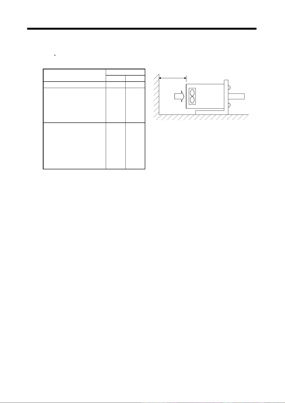
2. INSTALLATION
2.6 Cooling fan
The HA-LH
HA-LF and HA-LFS servo motors have a cooling fan. Leave the following distance between
the servo motor's suction face and the wall.
Servo Motor Series
HA-LH series 50 1.97
HA-LFS601 to 12K1
HA-LFS701M to 15K1M
HA-LFS11K2 to 22K2
HA-LFS6014 to 12K14
HA-LFS701M4 to 15K1M4
HA-LFS11K24 to 22K24
HA-LF30K2/37K2
HA-LF30K24 to 55K24
HA-LFS15K1 to 37K1
HA-LFS22K1M to 37K1M
HA-LFS30K2/37K2
HA-LFS15K14 to 37K14
HA-LFS22K1M4 to 50K1M4
HA-LFS30K24 to 55K24
Distance L
[mm] [in]
100 3.94
150 5.91
L or longer
Servo motor
Cooling fan
Wind
2.7 Cable
The power supply and encoder cables routed from the servo motor should be fixed to the servo motor to
keep them unmovable. Otherwise, cable breaks may occur. In addition, do not modify the connectors,
terminals and others at the ends of the cables.
2 - 13
Page 45

2. INSTALLATION
MEMO
2 - 14
Page 46
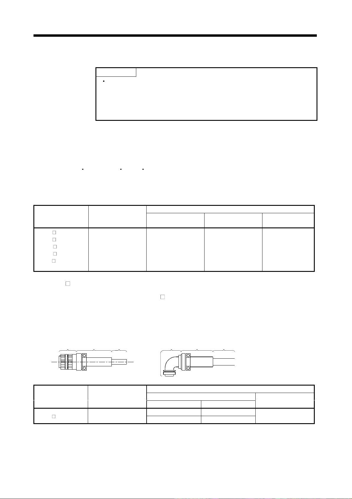
3. CONNECTORS USED FOR SERVO MOTOR WIRING
3. CONNECTORS USED FOR SERVO MOTOR WIRING
POINT
Protective structure indicated for cables and connecters is for a cable or
connector alone. When the cables and connectors are used to connect the
servo amplifier and servo motor, and if protective structures of the servo
amplifier and servo motor are lower than that of the cable and connector,
specifications of the servo amplifier and servo motor apply.
3.1 Makeups
This section gives connector makeups on an operating environment basis. Use the models of the
manufacturers given or equivalent.
3.1.1 HC-KF(-UE)
HC-MF(-UE) HA-FF HC-UF3000r/min series
Use round crimping terminals (1.25-4) for connection of the power supply and electromagnetic brake. For
connection of the encoder, use the connector indicated in this section or equivalent. This connector may be
used with the EN Standard and UL/C-UL Standard but is not waterproof.
Cable Side Connector
Connector Pin
(Tyco Electronics)
170359-1
170363-1 (loose piece)
Cable Clamp
(Toa Electric Industry)
MTI-0002
Servo Motor
HC-KF (B)
HC-KF
HC-MF
HC-MF
HA-FF
HC-UF13 to 73(B)
(B)-UE
(B)
(B) -UE
(B)
Connector Supplied for
Servo Motor
(Tyco Electronics)
1-172169-9 1-172161-9
(Tyco Electronics)
Housing
3.1.2 HA-FF C-UE series
If used with a waterproof connector, the HA-FF
C(B)-UE does not improve in ingress protection (IP54).
(1) Non-waterproof, UL/C-UL Standard-compliant
(a) When using cabtyre cables
1) For connection of power supply
1) Plug
2) Cable
clamp
Cable 1) Plug
2) Cable
clamp
Cable
Servo Motor
HA-FF C(B) -UE CE05-2A14S-2PD-B
Connector Supplied for
Servo Motor
Cable Side Connector
1) Plug (DDK)
Type Model
Straight D/MS3106B14S-2S
Angle D/MS3108B14S-2S
3 - 1
2) Cable clamp
(DDK)
D/MS3057-6A
Page 47
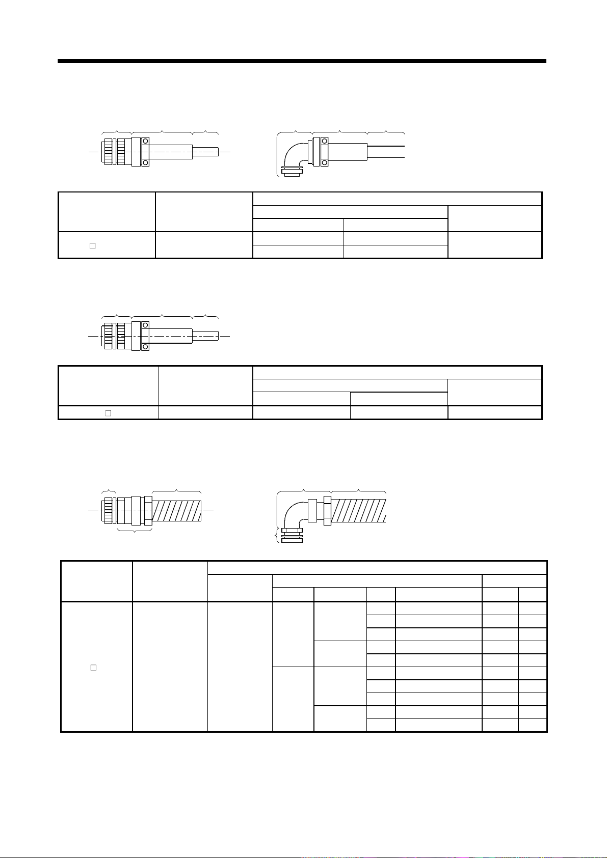
3. CONNECTORS USED FOR SERVO MOTOR WIRING
2) For connection of encoder
1) Plug
2) Cable
clamp
Cable 1) Plug
2) Cable
clamp
Cable
Connector Supplied for
Servo Motor
HA-FF C(B) -UE MS3102A20-29P
1) Plug (DDK)Servo Motor
Type Model
Straight D/MS3106B20-29S
Angle D/MS3108B20-29S
Cable Side Connector
2) Cable clamp
D/MS3057-12A
3) For connection of brake
2) Cable
1) Plug
Servo Motor
HA-FF CB-UE MS3102A10SL-4P Straight D/MS3106A10SL-4S D/MS3057-4A
clamp
Cable
Connector Supplied for
Servo Motor
Cable Side Connector
Plug (DDK)
Type Model
2) Cable clamp
(b) When using flexible conduits
1) For connection of power supply
2) Connector for
1) Plug Conduit
conduit
Conduit
(DDK)
(DDK)
2) Connector for conduit
Servo Motor
HA-FF C(B) -UE CE05-2A14S-2PD-B
Connector Supplied
for Servo Motor
1) Plug
1) Plug
(DDK)
D/ MS3106A14S-
2S(D190)
Cable Side Connector
2) Cable Connector Conduit
Type Manufacturer Size Model Model ID
1/4 RCC-102RL-MS14F VF-02 8.3
Nippon flex
Straight
Daiwa
Dengyo
Nippon flex
Angle
Daiwa
Dengyo
3/8 RCC-103RL-MS14F VF-03 10.6
1/2 RCC-104RL-MS14F VF-04 14.0
10 MSA-10-14 FCV10 10.0
12 MSA-12-14 FCV12 12.3
1/4 RCC-302RL-MS14F VF-02 8.3
3/8 RCC-303RL-MS14F VF-03 10.6
1/2 RCC-304RL-MS14F VF-04 14.0
10 MAA-10-14 FCV10 10.0
12 MAA-12-14 FCV12 12.3
3 - 2
Page 48

3. CONNECTORS USED FOR SERVO MOTOR WIRING
2) For connection of encoder
2) Connector for
1) Plug Conduit
conduit
Conduit
2) Connector for conduit
Servo Motor
HA-FF C(B) -UE MS3102A20-29P
Connector Supplied
for Servo Motor
3) For connection of brake
1) Plug Conduit
2) Connector for conduit
1) Plug
1) Plug
(DDK)
D/MS3106A20-
29S(D190)
1) Plug
Cable Side Connector
2) Cable Connector Conduit
Type Manufacturer Size Model Model ID
Nippon flex
Straight
Nippon flex
Angle
2) Connector for
conduit
Daiwa
Dengyo
Daiwa
Dengyo
Conduit
1/2 RCC-104RL-MS20F VF-04 14.0
3/4 RCC-106RL-MS20F VF-06 19.0
16 MSA-16-20 FCV16 15.8
22 MSA-22-20 FCV22 20.8
1/2 RCC-304RL-MS20F VF-04 14.0
3/4 RCC-306RL-MS20F VF-06 19.0
16 MAA-16-20 FCV16 15.8
22 MAA-22-20 FCV22 20.8
Servo Motor
HA-FF CB-UE MS3102A10SL-4P
Connector Supplied
for Servo Motor
1) Plug
(DDK)
D/MS3106A10SL-
4S(D190)
Cable Side Connector
2) Cable Connector Conduit
Type Manufacturer Size Model Model ID
Nippon flex 1/4 RCC-102RL-MS10F VF-02 8.3
Straight
Angle
Daiwa
Dengyo
Nippon flex 1/4 RCC-302RL-MS10F VF-02 8.3
Daiwa
Dengyo
10 MSA-10-10 FCV10 10.0
10 MAA-10-10 FCV10 10.0
3 - 3
Page 49

3. CONNECTORS USED FOR SERVO MOTOR WIRING
(2) EN Standard, UL/C-UL Standard-compliant
(a) When using cabtyre cables
1) For connection of power supply
2) Connector for
1) Plug
Cable
cable
Cable
2) Connector for cable
Connector Supplied for
Servo Motor
HA-FF C(B) -UE CE05-2A14S-2PD-B CE05-6A14S-2SD-D
1) Plug
1) Plug
(DDK)
2) For connection of encoder
3) Cable
1) Plug
2) Back shell
clamp
Cable 2) Back shell
1) Plug
Cable Side Connector
2) Connector for CableServo Motor
Type Manufacturer Cable OD Model
Nippon flex
Straight
Daiwa Dengyo
Nippon flex
Angle
Daiwa Dengyo
Cable
3) Cable clamp
4 to 8 ACS-08RL-MS14F
8 to 12 ACS-12RL-MS14F
5 to 8.3 YSO14-5 to 8
8.3 to 11.3 YSO14-9 to 11
4 to 8 ACA-08RL-MS14F
8 to 12 ACA-12RL-MS14F
5 to 8.3 YLO14-5 to 8
8.3 to 11.3 YLO14-9 to 11
Servo Motor
HA-FF C(B) -UE MS3102A20-29P D/MS3106A20-29S(D190)
Connector Supplied
for Servo Motor
1) Plug
(DDK)
3 - 4
Cable Side Connector
2) Back Shell
(DDK)
Type Model Cable OD Model
Straight CE02-20BS-S-D
Angle CE-20BA-S-D
3) Cable Clamp
(DDK)
6.8 to 10 CE3057-12A-3-D
Page 50

3. CONNECTORS USED FOR SERVO MOTOR WIRING
r
3) For connection of brake
1) Plug
Cable
2) Connector for cable
Cable
2) Connector for cable
Servo Motor
HA-FF CB-UE MS3102A10SL-4P D/MS3106A10SL-4S(D190)
Connector Supplied for
Servo Motor
1) Plug
1) Plug
(DDK)
(b) When using flexible conduits
1) For connection of power supply
2) Connector fo
1) Plug Conduit
2) Connector for conduit
conduit
1) Plug
Cable Side Connector
2) Cable Connector
Type Manufacturer Cable OD Model
4 to 8 ACS-08RL-MS10F
8 to 12 ACS-12RL-MS10F
4 to 8 ACA-08RL-MS10F
8 to 12 ACA-12RL-MS10F
Straight
Angle
Conduit
Nippon flex
Daiwa Dengyo 5 to 8.3 YS010-5 to 8
Nippon flex
Daiwa Dengyo 5 to 8.3 YL010-5 to 8
Servo Motor
HA-FF C(B) -UE CE05-2A14S-2PD-B
Connector Supplied
for Servo Motor
1) Plug
(DDK)
CE05-6A14S-
2SD-D
Cable Side Connector
2) Cable Connector Conduit
Type Manufacturer Size Model Model ID
1/4 RCC-102RL-MS14F VF-02 8.3
Nippon flex
Straight
Daiwa
Dengyo
Nippon flex
Angle
Daiwa
Dengyo
3/8 RCC-103RL-MS14F VF-03 10.6
1/2 RCC-104RL-MS14F VF-04 14.0
10 MSA-10-14 FCV10 10.0
12 MSA-12-14 FCV12 12.3
1/4 RCC-302RL-MS14F VF-02 8.3
3/8 RCC-303RL-MS14F VF-03 10.6
1/2 RCC-304RL-MS14F VF-04 14.0
10 MAA-10-14 FCV10 10.0
12 MAA-12-14 FCV12 12.3
3 - 5
Page 51

3. CONNECTORS USED FOR SERVO MOTOR WIRING
2) For connection of encoder
2) Connector for
1) Plug Conduit
conduit
Conduit
2) Connector for conduit
Connector Supplied
for Servo Motor
HA-FF C(B) -UE MS3102A20-29P
3) For connection of brake
1) Plug Conduit
2) Connector for conduit
1) Plug
1) Plug
(DDK)
D/MS3106A20-
29S(D190)
1) Plug
Cable Side Connector
2) Cable Connector ConduitServo Motor
Type Manufacturer Size Model Model ID
Nippon flex
Straight
Nippon flex
Angle
2) Connector for
conduit
Daiwa
Dengyo
Daiwa
Dengyo
Conduit
1/2 RCC-104RL-MS20F VF-04 14.0
3/4 RCC-106RL-MS20F VF-06 19.0
16 MSA-16-20 FCV16 15.8
22 MSA-22-20 FCV22 20.8
1/2 RCC-304RL-MS20F VF-04 14.0
3/4 RCC-306RL-MS20F VF-06 19.0
16 MAA-16-20 FCV16 15.8
22 MAA-22-20 FCV22 20.8
Connector Supplied
for Servo Motor
HA-FF CB -UE MS3102A10SL-4P
1) Plug
(DDK)
D/MS3106A10SL-
4S(D190)
Cable Side Connector
2) Cable Connector ConduitServo Motor
Type Manufacturer Size Model Model ID
Nippon flex 1/4 RCC-102RL-MS10F VF-02 8.3
Straight
Angle
Daiwa
Dengyo
Nippon flex 1/4 RCC-302RL-MS10F VF-02 8.3
Daiwa
Dengyo
10 MSA-10-10 FCV10 10.0
10 MAA-10-10 FCV10 10.0
3 - 6
Page 52
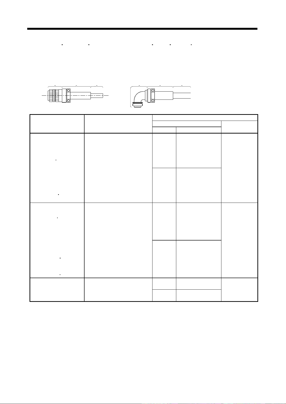
3. CONNECTORS USED FOR SERVO MOTOR WIRING
3.1.3 HC-SF(S) HC-RF(S) HC-UF(S)2000r/min, HA-LH HA-LF HA-LFS HC-LFS series
(1) Non-waterproof, UL/C-UL Standard-compliant
(a) When using cabtyre cables
1) For connection of power supply
2) Cable
1) Plug
Servo Motor Connector Supplied for Servo Motor
HC-SF81(B)
HC-SF52(B) to 152(B)
HC-SF53(B) to 153(B)
HC-RF103(B) to 203(B)
HC-UF72(B)
HC-SFS81(B)
HC-SFS52(B) to 152(B)
HC-SFS53(B) to 153(B)
HC-SFS524(B) to 1524(B)
HC-RFS103(B) to 203(B)
HC-UFS72(B)
HC-LFS52(B) to 152(B)
HC-SF121(B) to 301(B)
HC-SF202(B) to 502(B)
HC-SF203(B)
HC-RF353(B) to 503(B)
HC-UF202(B) to 502(B)
HC-SFS121(B) to 301(B)
HC-SFS202(B) to 502(B)
HC-SFS203(B) to 353(B)
HC-SFS2024(B) to 5024(B)
HC-RFS353(B)
HC-UFS202(B) to 502(B)
HA-LFS502
HC-LFS202(B)
HC-SF702(B)
HC-SFS702(B)
HC-SFS7024(B)
HA-LFS702
clamp
152(B)
152(B)
353(B)
503(B)
302(B)
Cable 1) Plug
CE05-2A22-23PD-B
CE05-2A24-10PD-B
CE05-2A32-17PD-B
2) Cable
clamp
Type Model
Straight D/MS3106B22-23S
Angle D/MS3108B22-23S
Straight D/MS3106B24-10S
Angle D/MS3108B24-10S
Straight D/MS3106B32-17S
Angle D/MS3108B32-17S
Cable
Cable Side Connector
1) Plug (DDK)
2) Cable clamp
(DDK)
D/MS3057-12A
D/MS3057-16A
D/MS3057-20A
3 - 7
Page 53

3. CONNECTORS USED FOR SERVO MOTOR WIRING
2) For connection of encoder
1) Plug
2) Cable
clamp
Cable 1) Plug
2) Cable
clamp
Cable
HC-SF81(B) to 301(B)
HC-SF52(B) to 702(B)
HC-SF53(B) to 353(B)
HC-RF103(B) to 503(B)
HC-UF72(B) to 502(B)
HC-SFS81(B) to 301(B)
HC-SFS52(B) to 702(B)
HC-SFS53(B) to 353(B)
HC-SFS524(B) to 7024(B)
HC-RFS103(B) to 503(B)
HC-UFS72(B) to 502(B)
HA-LH11K2 to 22K2
HA-LF30K24 to 55K24
HA-LF30K2
HA-LFS601 to 37K1
HA-LFS701M to 37K1M
HA-LFS502 to 37K2
HA-LFS6014 to 37K14
HA-LFS701M4 to 50K1M4
HA-LFS11K24 to 55K24
HC-LFS52(B) to 302(B)
37K2
Connector Supplied for
Servo Motor
MS3102A20-29P
Cable Side Connector
1) Plug (DDK)Servo Motor
Type Model
Straight D/MS3106B20-29S
Angle D/MS3108B20-29S
2) Cable clamp
(DDK)
D/MS3057-12A
3) For connection of brake
1) Plug
2) Connector for cable
Servo Motor
HC-SF121B to 301B
HC-SF202B to 702B
HC-SF203B
HC-UF202B to 502B
HC-SFS121B to 301B
HC-SFS202B to 702B
HC-SFS203B
HC-SFS2024B to 7024B
HC-UFS202B to 502B
HC-LFS202B
353B
353B
302B
Cable
Connector Supplied
for Servo Motor
MS3102A10SL-4P
2) Connector for cable
1) Plug
1) Plug
(DDK)
D/MS3106A10SL-
4S (D190)
3 - 8
Cable
Cable Side Connector
2) Connector for Cable
Type Manufacturer
Nippon flex
Straight
Daiwa
Dengyo
Nippon flex
Angle
Daiwa
Dengyo
Cable
OD
4 to 8 ACS-08RL-MS10F
8 to 12 ACS-12RL-MS10F
5 to 8.3 YSO10-5 to 8
4 to 8 ACA-08RL-MS10F
8 to 12 ACA-12RL-MS10F
5 to 8.3 YLO10-5 to 8
Model
Page 54

3. CONNECTORS USED FOR SERVO MOTOR WIRING
(b) When using flexible conduits
1) For connection of power supply
2) Connector for
1) Plug Conduit
conduit
Conduit
2) Connector for conduit
Servo Motor
HC-SF81(B)
HC-SF52(B) to 152(B)
HC-SF53(B) to 153(B)
HC-RF103(B) to 203(B)
HC-UF72(B)
HC-SFS81(B)
HC-SFS52(B) to 152(B)
HC-SFS53(B) to 153(B)
HC-SFS524(B) to 1524(B)
HC-RFS103(B) to 203(B)
HC-UFS72(B)
HC-LFS52(B) to 152(B)
HC-SF121(B) to 301(B)
HC-SF202(B) to 502(B)
HC-SF203(B)
HC-RF353(B) to 503(B)
HC-UF202(B) to 502(B)
HC-SFS121(B) to 301(B)
HC-SFS202(B) to 502(B)
HC-SFS203(B) to 353(B)
HC-SFS2024(B) to 5024(B)
HC-RFS353(B)
HC-UFS202(B) to 502(B)
HA-LFS502
HC-LFS202(B)
HC-SF702(B)
HC-SFS702(B)
HC-SFS7024(B)
HA-LFS702
152(B)
152(B)
352(B)
503(B)
302(B)
Connector
Supplied
for Servo
Motor
CE052A22-
23PD-B
CE052A24-
10PD-B
CE052A32-
17PD-B
1) Plug
1) Plug
(DDK)
D/MS3106A22-
23S(D190)
D/MS3106A24-
10S(D190)
D/MS3106A32-
17S(D190)
Cable Side Connector
2) Connector for conduit Conduit
Type Manufacturer Size Model Model ID
1/2 RCC-104RL-MS22F VF-04 14.0
3/4 RCC-106RL-MS22F VF-06 19.0Nippon flex
Straight
Daiwa
Dengyo
Angle
Daiwa
Dengyo
Nippon flex
Straight
Daiwa
Dengyo
Angle
Daiwa
Dengyo
Straight Nippon flex
Angle
Daiwa
Dengyo
1 RCC-108RL-MS22F VF-08 24.4
16 MSA-16-22 FCV16 15.8
22 MSA-22-22 FCV22 20.8
28 MSA-28-22 FCV28 26.4
1/2 RCC-304RL-MS22F VF-04 14.0
3/4 RCC-306RL-MS22F VF-06 19.0Nippon flex
1 RCC-308RL-MS22F VF-08 24.4
16 MAA-16-22 FCV16 15.8
22 MAA-22-22 FCV22 20.8
28 MAA-28-22 FCV28 26.4
1/2 RCC-104RL-MS24F VF-04 14.0
3/4 RCC-106RL-MS24F VF-06 19.0
1 RCC-108RL-MS24F VF-08 24.4
16 MSA-16-24 FCV16 15.8
22 MSA-22-24 FCV22 20.8
28 MSA-28-24 FCV28 26.4
1/2 RCC-304RL-MS24F VF-04 14.0
3/4 RCC-306RL-MS24F VF-06 19.0Nippon flex
1 RCC-308RL-MS24F VF-08 24.4
16 MAA-16-24 FCV16 15.8
22 MAA-22-24 FCV22 20.8
28 MAA-28-24 FCV28 26.4
3/4 RCC-106RL-MS32F VF-06 19.0
1 RCC-108RL-MS32F VF-08 24.4
3/4 RCC-306RL-MS32F VF-06 19.0
1 RCC-308RL-MS32F VF-08 24.4
3 - 9
Page 55
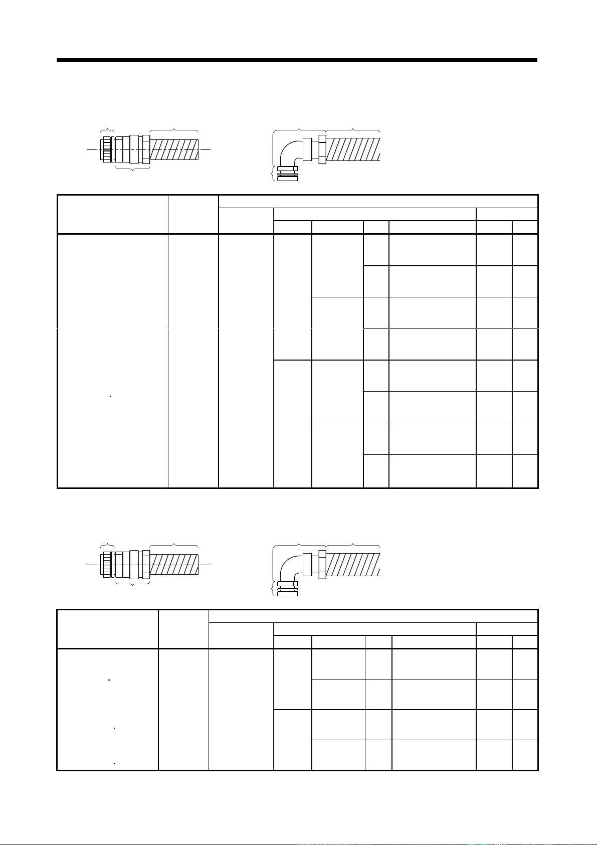
3. CONNECTORS USED FOR SERVO MOTOR WIRING
2) For connection of encoder
2) Connector for
1) Plug Conduit
conduit
Conduit
2) Connector for conduit
HC-SF81(B) to 301(B)
HC-SF52(B) to 702(B)
HC-SF53(B) to 353(B)
HC-RF103(B) to 503(B)
HC-UF72(B) to 502(B)
HC-SFS81(B) to 301(B)
HC-SFS52(B) to 702(B)
HC-SFS53(B) to 353(B)
HC-SFS5024(B) to 7024(B)
HC-RFS103(B) to 503(B)
HC-UFS72(B) to 502(B)
HA-LH11K2 to 22K2
HA-LF30K24 to 55K24
HA-LF30K2
HA-LFS601 to 37K1
HA-LFS701M to 37K1M
HA-LFS502 to 37K2
HA-LFS6014 to 37K14
HA-LFS701M4 to 50K1M4
HA-LFS11K24 to 55K24
HC-LFS52(B) to 302(B)
37K2
Connector
Supplied for
Servo Motor
MS3102A20-
29P
1) Plug
1) Plug
(DDK)
D/MS3106A20-
29S(D190)
Cable Side Connector
2) Connector for conduit ConduitServo Motor
Type Manufacturer Size Model Model ID
1/2 RCC-104RL-MS20F VF-04 14.0
Nippon flex
3/4 RCC-106RL-MS20F VF-06 19.0
Straight
16 MSA-16-20 FCV16 15.8
Daiwa
Dengyo
22 MSA-22-20 FCV22 20.8
1/2 RCC-304RL-MS20F VF-04 14.0
Nippon flex
3/4 RCC-306RL-MS20F VF-06 19.0
Angle
16 MAA-16-20 FCV16 15.8
Daiwa
Dengyo
22 MAA-22-20 FCV22 20.8
3) For connection of brake
1) Plug Conduit
2) Connector for conduit
HC-SF121B to 301B
HC-SF202B to 702B
HC-SF203B
HC-UF202B to 502B
HC-SFS121B to 301B
HC-SFS202B to 702B
HC-SFS203B
HC-SFS2024B to 7024B
HC-UFS202B to 502B
HC-LFS202B
353B
353B
302B
Connector
Supplied for
Servo Motor
MS3102A
10SL-4P
1) Plug
1) Plug
(DDK)
D/MS3106A10SL-
4S(D190)
2) Connector for
conduit
Type Manufacturer Size Model Model ID
Straight
Angle
Conduit
Cable Side Connector
2) Connector for conduit ConduitServo Motor
Nippon flex 1/4 RCC-102RL-MS10F VF-02 8.3
Daiwa
Dengyo
Nippon flex 1/4 RCC-302RL-MS10F VF-02 8.3
Daiwa
Dengyo
10 MSA-10-10 FCV10 10
10 MAA-10-10 FCV10 10
3 - 10
Page 56

3. CONNECTORS USED FOR SERVO MOTOR WIRING
(2) Waterproof (IP65), EN Standard, UL/C-UL Standard-compliant
(a) When using cabtyre cables
1) For connection of power supply
1) Plug
2) Cable
clamp
Cable 1) Plug
2) Cable
clamp
Cable
Servo Motor
HC-SF81(B)
HC-SF52(B) to 152(B)
HC-SF53(B) to 153(B)
HC-RF103(B) to 203(B)
HC-UF72(B)
HC-SFS81(B)
HC-SFS52(B) to 152(B)
HC-SFS53(B) to 153(B)
HC-SFS524(B) to 1524(B)
HC-RFS103(B) to 203(B)
HC-UFS72(B)
HC-LFS52(B) to 152(B)
HC-SF121(B) to 301(B)
HC-SF202(B) to 502(B)
HC-SF203(B)
HC-RF353(B) to 503(B)
HC-UF202(B) to 502(B)
HC-SFS121(B) to 301(B)
HC-SFS202(B) to 502(B)
HC-SFS203(B)
HC-SFS2024(B) to 5024(B)
HC-RFS353(B)
HC-UFS202(B) to 502(B)
HA-LFS502
HC-LFS202(B)
HC-SF702(B)
HC-SFS702(B)
HC-SFS7024(B)
HA-LFS702
152(B)
152(B)
353(B)
353(B)
503(B)
302(B)
Connector
Supplied for
Servo Motor
CE05-2A22-
23PD-B
CE05-2A24-
10PD-B
CE05-2A32-
17PD-B
Cable Side Connector
1) Plug (DDK)
Type Model Cable OD Model
Straight CE05-6A22-23SD-D-BSS 9.5 to 13 CE3057-12A-2-D
Angle CE05-8A22-23SD-D-BAS 12.5 to 16 CE3057-12A-1-D
Straight CE05-6A24-10SD-D-BSS 13 to 15.5 CE3057-16A-2-D
Angle CE05-8A24-10SD-D-BAS 15 to 19.1 CE3057-16A-1-D
Straight CE05-6A32-17SD-D-BSS
22 to 23.8 CE3057-20A-1-D
Angle CE05-8A32-17SD-D-BAS
2) Cable clamp
(DDK)
3 - 11
Page 57

3. CONNECTORS USED FOR SERVO MOTOR WIRING
2) For connection of encoder
3) Cable
1) Plug
clamp
Cable 2) Back shell
Cable
2) Back shell
Servo Motor
HC-SF81(B) to 301(B)
HC-SF52(B) to 702(B)
HC-SF53(B) to 353(B)
HC-RF103(B) to 503(B)
HC-UF72(B) to 502(B)
HC-SFS81(B) to 301(B)
HC-SFS52(B) to 702(B)
HC-SFS53(B) to 353(B)
HC-SFS524(B) to 7024(B)
HC-RFS103(B) to 502(B)
HC-UFS72(B) to 502(B)
HA-LH11K2 to 22K2
HA-LF30K24 to 55K24
HA-LF30K2
HA-LFS601 to 37K1
HA-LFS701M to 37K1M
HA-LFS502 to 37K2
HA-LFS6014 to 37K14
HA-LFS701M4 to 50K1M4
HA-LFS11K24 to 55K24
HC-LFS52(B) to 302(B)
37K2
Connector
Supplied for
Servo Motor
MS3102A20-29P
1) Plug
1) Plug
(DDK)
D/MS3106A20-
29S(D190)
3) Cable clamp
Cable Side Connector
2) Back shell
Type Model Cable OD Model
Straight CE02-20BS-S-D
Angle CE-20BA-S-D
3) Cable clamp
(DDK)
6.8 to 10 CE3057-12A-3-D
3) For connection of brake
1) Plug
2) Connector for cable
Servo Motor
HC-SF121B to 301B
HC-SF202B to 702B
HC-SF203B
HC-UF202B to 502B
HC-SFS121B to 301B
HC-SFS202B to 702B
HC-SFS203B
HC-SFS2024B to 7024B
HC-UFS202B to 502B
HC-LFS202B
HA-LFS601B to 801B
HA-LFS701MB to 15K1MB
HA-LFS11K2B to 22K2B
HA-LFS6014B to 8014B
HA-LFS701M4B to 15K1M4B
HA-LFS11K24B to 22K24B
353B
353B
302B
Cable
Connector Supplied
for Servo Motor
MS3102A10SL-4P
1) Plug
D/MS3106A10SL-
2) Connector for
cable
1) Plug
(DDK)
4S(D190)
Cable
Cable Side Connector
2) Connector for Cable
Type Manufacturer Cable OD Model
4 to 8 ACS-08RL-MS10F
Nippon flex
Straight
Daiwa
Dengyo
Nippon flex
Angle
Daiwa
Dengyo
8 to 12 ACS-12RL-MS10F
5 to 8.3 YSO-10-5 to 8
4 to 8 ACA-08RL-MS10F
8 to 12 ACA-12RL-MS10F
5 to 8.3 YLO-10-5 to 8
3 - 12
Page 58

3. CONNECTORS USED FOR SERVO MOTOR WIRING
r
(b) When using flexible conduits
1) For connection of power supply
2) Connector fo
1) Plug Conduit
conduit
Conduit
2) Connector for conduit
Servo Motor
HC-SF81(B)
HC-SF52(B) to 152(B)
HC-SF53(B) to 153(B)
HC-RF103(B) to 203(B)
HC-UF72(B)
HC-SFS81(B)
HC-SFS52(B) to 152(B)
HC-SFS53(B) to 153(B)
HC-SFS524(B) to 1524(B)
HC-RFS103(B) to 203(B)
HC-UFS72(B)
HC-LFS52(B) to 152(B)
HC-SF121(B) to 301(B)
HC-SF202(B) to 502(B)
HC-SF203(B)
HC-RF353(B) to 503(B)
HC-UF202(B) to 502(B)
HC-SFS121(B) to 301(B)
HC-SFS202(B) to 502(B)
HC-SFS203(B)
HC-SFS2024(B) to 5024(B)
HC-RFS353(B)
HC-UFS202(B) to 502(B)
HA-LFS502
HC-LFS202(B)
HC-SF702(B)
HC-SFS702(B)
HC-SFS7024(B)
HA-LFS702
152(B)
152(B)
353(B)
353(B)
503(B)
302(B)
Connector
Supplied for
Servo Motor
CE05-2A22-
23PD-B
CE05-2A24-
10PD-B
CE05-2A32-
17PD-B
1) Plug
1) Plug
(DDK)
CE05-6A22-
23SD-D
CE05-6A24-
10SD-D
CE05-6A32-
17SD-D
Cable Side Connector
2) Connector for conduit Conduit
Type Manufacturer Size Model Model ID
1/2 RCC-104RL-MS22F VF-04 14.0
Nippon flex
Straight
Daiwa
Dengyo
Nippon flex
Angle
Daiwa
Dengyo
Straight
Daiwa
Dengyo
Nippon flex
Angle
Daiwa
Dengyo
Straight Nippon flex
Angle Nippon flex
3/4 RCC-106RL-MS22F VF-06 19.0
1 RCC-108RL-MS22F VF-08 24.4
16 MSA-16-22 FCV16 15.8
22 MSA-22-22 FCV22 20.8
28 MSA-28-22 FCV28 26.4
1/2 RCC-304RL-MS22F VF-04 14.0
3/4 RCC-306RL-MS22F VF-06 19.0
1 RCC-308RL-MS22F VF-08 24.4
16 MAA-16-22 FCV16 15.8
22 MAA-22-22 FCV22 20.8
28 MAA-28-22 FCV28 26.4
1/2 RCC-104RL-MS24F VF-04 14.0
3/4 RCC-106RL-MS24F VF-06 19.0Nippon flex
1 RCC-108RL-MS24F VF-08 24.4
16 MSA-16-24 FCV16 15.8
22 MSA-22-24 FCV22 20.8
28 MSA-28-24 FCV28 26.4
1/2 RCC-304RL-MS24F VF-04 14.0
3/4 RCC-306RL-MS24F VF-06 19.0
1 RCC-308RL-MS24F VF-08 24.4
16 MAA-16-24 FCV16 15.8
22 MAA-22-24 FCV22 20.8
28 MAA-28-24 FCV28 26.4
3/4 RCC-106RL-MS32F VF-06 19.0
1 RCC-108RL-MS32F VF-08 24.4
3/4 RCC-306RL-MS32F VF-06 19.0
1 RCC-308RL-MS32F VF-08 24.4
3 - 13
Page 59

3. CONNECTORS USED FOR SERVO MOTOR WIRING
2) For connection of encoder
2) Connector for
1) Plug Conduit
conduit
Conduit
2) Connector for conduit
HC-SF81(B) to 301(B)
HC-SF52(B) to 702(B)
HC-SF53(B) to 353(B)
HC-RF103(B) to 503(B)
HC-UF72(B) to 502(B)
HC-SFS81(B) to 301(B)
HC-SFS52(B) to 702(B)
HC-SFS53(B) to 353(B)
HC-SFS524(B) to 7024(B)
HC-RFS103(B) to 503(B)
HC-UFS72(B) to 502(B)
HA-LH11K2 to 22K2
HA-LF30K24 to 55K24
HA-LF30K2
HA-LFS601 to 37K1
HA-LFS701M to 37K1M
HA-LFS502 to 37K2
HA-LFS6014 to 37K14
HA-LFS701M4 to 50K1M4
HA-LFS11K24 to 55K24
HC-LFS52(B) to 302 (B)
37K2
3) For connection of brake
1) Plug Conduit
Connector
Supplied for
Servo Motor
MS3102A20-
29P
1) Plug
1) Plug
(DDK)
D/MS3106A20-
29S(D190)
Cable Side Connector
2) Connector for conduit ConduitServo Motor
Type Manufacturer Size Model Model ID
1/2 RCC-104RL-MS20F VF-04 14.0
Nippon flex
3/4 RCC-106RL-MS20F VF-06 19.0
Straight
16 MSA-16-20 FCV16 15.8
22 MSA-22-20 FCV22 20.8
1/2 RCC-304RL-MS20F VF-04 14.0
3/4 RCC-306RL-MS20F VF-06 19.0
16 MAA-16-20 FCV16 15.8
22 MAA-22-20 FCV22 20.8
Nippon flex
Angle
2) Connector for
conduit
Daiwa
Dengyo
Daiwa
Dengyo
Conduit
2) Connector for conduit
HC-SF121B to 301B
HC-SF202B to 702B
HC-SF203B
HC-UF202B to 502B
HC-SFS121B to 301B
HC-SFS202B to 702B
HC-SFS203B
HC-SFS2024B to 7024B
HC-UFS202B to 502B
HC-LFS202B
HA-LFS601B to 801B
HA-LFS701MB to 15K1MB
HA-LFS11K2B to 22K2B
HA-LFS6014B to 8014B
HA-LFS701M4B to 15K1M4B
HA-LFS11K24B to 22K24B
353B
353B
302B
1) Plug
Connector
Supplied for
Servo Motor
MS3102A10SL-4PD/MS3106A10SL-
1) Plug
(DDK)
4S(D190)
3 - 14
Cable Side Connector
2) Connector for conduit ConduitServo Motor
Type Manufacturer Size Model Model ID
Nippon flex 1/4 RCC-102RL-MS10F VF-02 8.3
Straight
Daiwa
Dengyo
Nippon flex 1/4 RCC-302RL-MS10F VF-02 8.3
Angle
Daiwa
Dengyo
10 MSA-10-10 FCV10 10
10 MAA-10-10 FCV10 10
Page 60
3. CONNECTORS USED FOR SERVO MOTOR WIRING
3.1.4 HC-AQ series
Servo Motor
HC-AQ (B) (Note) 5557-12R-210 5559-12P-210 5558
Note. Terminal: 5556
Servo Motor Side Connector
(Molex)
Cable Side Connector (Molex)
Plug Terminal
3.1.5 HC-KFS HC-MFS HC-UFS3000r/min series
Use the connectors indicated in this section or equivalent for connection of the power supply,
electromagnetic brake and encoder. These connectors may be used for the EN Standard and UL/C-UL
Standard but are not waterproof.
(1) For connection of power supply and brake
Servo Motor
HC-KFS
HC-MFS
HC-UFS13 to 73
Servo Motor
HC-KFS B
HC-MFS
HC-UFS13 to 73B
B
Connector Supplied for
Servo Motor (Molex)
5557-04R-210 5559-04P-210 5558PBT3L 57022-5300
Connector Supplied for
Servo Motor (Molex)
5557-06R-210 5559-06P-210 5558PBT3L 57022-5300
Plug (Molex) Terminal (Molex)
Plug (Molex) Terminal (Molex)
Cable Side Connector
Cable Side Connector
Manual crimping tool
Manual crimping tool
(2) For connection of encoder
Connector Supplied for
Servo Motor
HC-KFS (B)
HC-MFS
HC-UFS13 to 73(B)
(B)
Servo Motor
(Tyco Electronics)
1-172169-9 1-172161-9
Housing (Tyco Electronics)
Cable Side Connector
Connector pin
(Tyco Electronics)
170359-1
170363-1 (loose piece)
Cable clamp
(Toa Electric Industry)
MTI-0002
3 - 15
Page 61
3. CONNECTORS USED FOR SERVO MOTOR WIRING
3.1.6 HC-UF3000r/min series (Compliance with IP65)
Use the connectors indicated in this section or equivalent for connection of the power supply,
electromagnetic brake and encoder. These connectors are waterproof.
(1) For connection of power
Connector
Servo Motor
HC-UF (B)-S1
HC-UFS
Note. The numeral within the parentheses indicates the applicable cable diameter. It depends on the used cable diameter.
(B)-S1
Supplied for
Servo Motor
(Hirose Electric)
RM15WTP-4P RM15WTJA-4S (Note) RM15WTP-CP(8)
Plug (Hirose Electric) Cable clamp (Hirose Electric)
(2) For connection of encoder
Connector
Servo Motor
HC-UF (B)-S1
HC-UFS
Note. The numeral within the parentheses indicates the applicable cable diameter. It depends on the used cable diameter.
(B)-S1
Supplied for
Servo Motor
(Hirose Electric)
RM15WTP-10P (Note) RM15WTJA-10S-(7)
Plug (With cable clamp) (Hirose Electric) Cable clamp (Hirose Electric)
Cable Side Connector
Cable Side Connector
(3) For connection of brake
Connector
Servo Motor
HC-UF B-S1
HC-UFS
Note. The numeral within the parentheses indicates the applicable cable diameter. It depends on the used cable diameter.
B-S1
Supplied for
Servo Motor
(Hirose Electric)
RM15WTP-4P RM15WTJA-4S (Note) RM15WTP-CP(6)
Plug (Hirose Electric) Cable clamp (Hirose Electric)
Cable Side Connector
3 - 16
Page 62

3. CONNECTORS USED FOR SERVO MOTOR WIRING
3.2 IP65, EN Standard-compliant options
The following options are available to satisfy the IP65 ingress protection and EN Standard.
To comply with the EN Standard, the power supply connector used must be any of these options or
equivalent.
Product Model Description Servo Motor
IP65-compliant
encoder cable
(For MR-J2 series
MR-J2-Super Series)
Encoder cable
(For MR-H-
N series)
MR-ENCBL
MR-EN1CBL
Servo amplifier side connector
M-H HC-SF series
(3M or equivalent)
Connector: 10120-3000PE
Shell kit: 10320-52F0-008
Servo amplifier side connector
M-H HC-SF series
(Honda Tsushin Kogyo)
Connector: PCR-S20FS
Case: PCR-LS20LA1
Encoder side connector
(DDK)
Plug: D/MS3106A20-29S(D190)
Cable clamp: CE3057-12A-3-D
Back shell: CE02-20BS-S-D
Encoder side connector
(DDK)
Plug: D/MS3106A20-29S(D190)
Cable clamp: CE3057-12A-3-D
Back shell: CE02-20BS-S-D
HC-RF series
HC-UF2000r/min
series
HA-LF-UE series
HA-FF-UE series
HC-SFS series
HC-RFS series
HC-UFS2000r/min
series
HA-LFS series
HC-LFS series
HC-RF series
HC-UF2000r/min
series
HA-LF-UE series
Encoder connector set
(For MR-J2 series
MR-J2-Super Series)
Encoder connector set
(For MR-H-
EN Standard-compliant
power connector set
N series)
MR-ENCNS
MR-EN1CNS
MR-PWCNF Plug: CE05-6A14S-2SD-D (DDK)
Servo amplifier side connector
(3M or equivalent)
Connector: 10120-3000PE
Shell kit: 10320-52F0-008
Servo amplifier side connector
(Honda Tsushin Kogyo)
Connector: PCR-S20FS
Case: PCR-LS20LA1
Cable connector: YSO14-9 to 11 (Daiwa De ngyo)
Encoder side connector
(DDK)
Plug: D/MS3106A20-29S(D190)
Cable clamp: CE3057-12A-3-D
Back shell: CE02-20BS-S-D
Encoder side connector
(DDK)
Plug: D/MS3106A20-29S(D190)
Cable clamp: CE3057-12A-3-D
Back shell: CE02-20BS-S-D
HC-SF series
HC-RF series
HC-UF2000r/min
series
HC-SFS series
HC-RFS series
HC-UFS2000r/min
series
HA-LFS series
HC-LFS series
HC-SF series
HC-RF series
HC-UF2000r/min
series
HA-LF series
HA-FF C-UE
series
3 - 17
Page 63

3. CONNECTORS USED FOR SERVO MOTOR WIRING
Product Model Description Servo Motor
IP65/EN
Standard-compliant
power connector set
IP65/EN
Standard-compliant
power connector set
Power connector set MR-PWCNS3 Plug:CE05-6A32-17SD-D-BSS
IP65/EN
Standard-compliant
brake connector set
Note. If it is used with the HA-FF C-UE, the servo motor does not improve in ingress protection (IP54).
MR-PWCNS1
MR-PWCNS2
MR-BKCN (Note)
Plug: CE05-6A22-23SD-D-BSS
Cable clamp: CE3057-12A-2-D
(DDK)
Plug: CE05-6A24-10SD-D-BSS
Cable clamp: CE3057-16A-2-D
(DDK)
Cable clamp: CE3057-20A-1-D
(DDK)
Plug: D/MS3106A10SL-4S(D190) (DDK)
Cable connector: YSO10-5 to 8 (Daiwa
Dengyo)
HC-SF81(B)
HC-SF52(B) to 152(B)
HC-SF53(B) to 153(B)
HC-RF103(B) to 203(B)
HC-UF72(B)
HC-SFS81(B)
HC-SFS52(B) to 152(B)
HC-SFS53(B) to 153(B)
HC-SFS524(B) to 1524(B)
HC-RFS103(B) to 203(B)
HC-UFS72(B)
HC-LFS52(B) to 152(B)
HC-SF121(B) to 301(B)
HC-SF202(B) to 502(B)
HC-SF203(B)
HC-RF353(B)
HC-UF202(B) to 502(B)
HC-SFS121(B) to 301(B)
HC-SFS202(B) to 502(B)
HC-SFS203(B)
HC-SFS2024(B) to 5024(B)
HC-RFS353(B)
HC-UFS202(B) to 502(B)
HA-LFS502
HC-LFS202(B)
HC-SF702(B)
HC-SFS702(B)
HC-SFS7024(B)
HA-LFS702
HA-FF
HC-SF121B to 301B
HC-SF202B to 702B
HC-SF203B
HC-UF202B
HC-SFS121B to 301B
HC-SFS202B to 702B
HC-SFS203B
HC-SFS2024B to 7024B
HC-RFS353B
HC-UFS202B to 502B
HC-LFS202B
152(B)
152(B)
353(B)
503(B)
353(B)
503(B)
302(B)
CB-UE
353B
502B
353B
503B
302B
3 - 18
Page 64

3. CONNECTORS USED FOR SERVO MOTOR WIRING
r
3.3 Signal arrangement of encoder connectors
The encoder connector of each servo motor has the following signal arrangement. The connectors shown
are as seen from the pin side.
Servo Motor Series Signal Arrangement
HC-KF(-UE) series
HC-MF(-UE) series
HA-FF series
HC-UF3000r/min series
HC-KFS series
HC-MFS series
HC-UFS3000r/min series
Encoder connectors
1-172169-9 (AMP)
123
MR
456
MD MDR
789
P5
MRR
LG SHD
BAT
HA-FF C-UE series
HC-SF series
HC-RF series
HC-UF2000r/min series
HA-LH series
HA-LF series
HC-SFS series
HC-RFS series
HC-UFS2000r/min series
HA-LFS series
HC-LFS series
HC-AQ series
Encoder connectors
B
M
A
L
K
TP
J
H
C
N
E
RS
F
G
Signal
Pin
A
B
MDR
C MR
D
D
MRR
E
F BAT
GLG
H
J
Motor connecto
12 6
MRR MR
11 5
LG P5
10 4
SHD
93
B1 B2
82
WU
71
VE
MD
Pin Signal
K
L
M
N
SHD
P
R LG
S
P5
T
3 - 19
Page 65

3. CONNECTORS USED FOR SERVO MOTOR WIRING
MEMO
3 - 20
Page 66

4. INSPECTION
4. INSPECTION
Before starting maintenance and/or inspection, turn off the power and wait for 15
minutes or more until the charge lamp turns off. Then, confirm that the voltage
between P and N is safe with a voltage tester and others. Otherwise, an electric
WARNING
(1) Inspection
It is recommended to make the following checks periodically.
(a) Check the servo motor bearings, brake section, etc. for unusual noise.
shock may occur. In addition, always confirm from the front of the servo amplifier
whether the charge lamp is off or not.
Any person who is involved in inspection should be fully competent to do the work.
Otherwise, you may get an electric shock. For repair and parts replacement,
contact your safes representative.
POINT
Do not disassemble and/or repair the equipment on customer side.
(b) Check the cables and the like for scratches and cracks. Especially when the junction cable is
movable, perform periodic inspection according to operating conditions.
(c) Check the servo motor shaft and coupling for misalignment.
(d) Check the power supply connector and encoder connector tightening screws for looseness.
(2) Life
The following parts must be changed periodically as listed below. If any part is found faulty, it must be
changed immediately even when it has not yet reached the end of its life, which depends on the
operating method and environmental conditions. For parts replacement, please contact your sales
representative.
Part Name Guideline of Life Remarks
Bearings 20,000 to 30,000 hours
Encoder 20,000 to 30,000 hours
Oil seal 5,000 hours
Cooling fan 20,000 hours
The Guideline of Life field gives the reference time. If any fault
is found before this time is reached, the part must be changed.
(a) Bearings
When the servo motor is run at rated speed under rated load, change the bearings in 20,000 to
30,000 hours as a guideline. This differs on the operating conditions. The bearings must also be
changed if unusual noise or vibration is found during inspection.
(b) Oil seal
Must be changed in 5,000 hours of operation at rated speed as a guideline. These parts must also
be changed if oil leakage, etc. is found during inspection.
4 - 1
Page 67

4. INSPECTION
MEMO
4 - 2
Page 68

5. SPECIFICATIONS
5. SPECIFICATIONS
5.1 Standard specifications
Servo Motor
Item
Applicable servo
amplifier
Continuous
running duty
(Note 1
Rated speed (Note 1) [r/min] 3000 3000
Maximum speed [r/min] 4500 4000
Instantaneous permissible speed [r/min] 5175 4600
Maximum torque
Power rate at continuous rated torque
Inertia moment
(Note 3)
Recommended ratio of load inertia moment to
servo motor shaft inertia moment (Note 2)
Regenerative
brake duty
[times/min]
(Note 4
Power supply capacity
Rated current [A] 0.85 0.85 1.5 2.8 5.1 0.6 1.1 1.3 1.9 2.5 3.6
Maximum current [A] 2.6 2.6 5 9 18 1.8 3.3 3.9 5.7 7.5 10.8
Speed/position detector
Accessories V ring
Insulation class Class B Class B
Structure
Environmental conditions (Note 7) Refer to section 2.1 Refer to section 2.1
Mass (Note 3)
11)
15)
MR-H AN/BN/ACN/TN 20 20 40 60 100 10 10 20 40 40 60
MR-J2Rated output [kW] 0.05 0.1 0.2 0.4 0.75 0.05 0.1 0.2 0.3 0.4 0.6
Rated
torque
J[104kg m2] 0.019 0.03 0.088 0.143 0.6 0.063 0.095 0.35 0.50 0.98 1.2
WK
Servo amplifier's
built-in regenerative
resistor
MR-H
MR-RB013(10W) (Note 5) (Note 5) 2071 1363 370
series
MR-RB033(30W) (Note 5) (Note 5) (Note 5) 4088 1109
MR-RB32(300W)
Servo amplifier' built-in
regenerative resistor
MR-J2
series
MR-RB032(30W) (Note 5) (Note 5) (Note 5) 3000 600 (Note 5) (Note 5) (Note 5) 950 450 360
MR-RB12(100W) (Note 5) (Note 5) 2400 (Note 5) 3200 1500 1200
A/B/C 10102040701010204040 60
[N m] 0.16 0.32 0.64 1.3 2.4 0.16 0.32 0.64 0.95 1.3 1.9
[oz
[N m] 0.48 0.95 1.9 3.8 7.2 0.48 0.95 1.9 2.9 3.8 5.7
[oz
[kW/s]
2
[oz in2] 0.104 0.16 0.48 0.78 3.28 0.344 0.52 1.91 2.73 5.36 6.56
[kg] 0.4 0.53 0.99 1.45 3.0 1.3 1.5 2.3 2.6 4.2 4.8
(ultra low inertia, small capacity)
053 13 23 43 73 053 13 23 33 43 63
in] 22.7 45.3 90.7 184 340 22.7 45.3 90.7 135 184 269
in] 68.0 135 269 538 1020 68.0 135 269 411 538 808
13.47 34.13 46 .02 116.55 94. 43 4.0 10.2 11.7 18. 1 17.2 30. 1
(Note 5) (Note 5) (Note 5) 4275 1726 (Note 5) (Note 5) (Note 5) 1500 750 600
(Note 5) (Note 5) (Note 5) 1010 400 (Note 5) (Note 5) (Note 5) 320 150 120
Refer to "Power supply equipment capacity and generated loss of servo amplifiers"
in Servo Amplifier Instruction Manual.
position and incremental detection
systems (Resolution per servo motor
(protection type: IP44 (Note 6
[lb] 0.88 1.17 2.18 3.20 6.61 2.87 3.31 5.07 5.73 9.26 10.6
HC-MF Series
30 times or less 10 times or less
(Note 5) (Note 5) (Note 5) (Note 5) 3983 3046
Encoder common to absolute
1 rotation : 8192 pulse/rev)
Totally-enclosed, self-cooled
12))
Encoder common to absolute position and
incremental detection systems (Resolution
per servo motor 1 rotation: 8192 pulse/rev)
(protection type: IP44 (Note 8 9 12))
HA-FF Series
(low inertia, small capacity)
Totally-enclosed, self-cooled
5 - 1
Page 69

5. SPECIFICATIONS
Servo Motor
Item
Applicable servo
amplifier
Continuous
running duty
(Note 1
Rated speed (Note 1) [r/min] 1000 2000
Maximum speed [r/min] 1500 1200 3000 2500 2000
Instantaneous permissible speed [r/min] 1725 1380 3450 2875 2300
Maximum torque
Power rate at continuous rated torque
(Note 3)
Recommended ratio of load inertia moment to
servo motor shaft inertia moment (Note 2)
Regenerative
brake duty
[times/min]
(Note 4)
Power supply capacity Refer to "Power supply equipment capacity and generated loss of servo amplifiers"
Rated current [A] 5.1 7.1 9.6 16 3.2 6 9 11 17 26 35
Maximum current [A] 15.3 21.3 28.8 48 9.6 18 27 33 51 84 105
Speed/position detector
Accessories Oil seal Oil seal
Insulation class Class F Class F
Structure
Environmental conditions (Note 7) Refer to section 2.1 Refer to section 2.1
Mass (Note 3)
11)
MR-H AN/BN/ACN/TN 100 200 200 350 60 100 200 200 350 500 700
MR-J2Rated output [kW] 0.85 1.2 2.0 3.0 0.5 1.0 1.5 2.0 3.5 5.0 7.0
Rated
torque
J[104kg m2] 20.0 42.5 82 101 6.6 13.7 20.0 42.5 82.0 101 160Inertia moment
WK
Servo amplifier's
built-in regenerative
resistor
MR-RB31(300W) 57
MR-RB32(300W) 1649 1241 638
MR-H
MR-RB30(300W) 326 100 90
series
MR-RB34(300W) 774 401 412 193
MR-RB50(500W) 543 167 150
MR-RB51(500W) 95
MR-RB54(500W) 1290 669 687 322
Servo amplifier' built-in
regenerative resistor
MR-RB032(30W) 220 165 80
MR-J2
MR-RB12(100W) 740 560 270
series
MR-RB32(300W) 2220 810
MR-RB30(300W) 730 330 250 408 192 95
MR-RB50(500W) 1216 550 430 680 320 158
[kg] 9.0 12 19 23 5.0 7.0 9.0 12.0 19.0 23 32
[lb] 19.8 26.5 41.9 50.7 11.0 15.4 19.8 26.5 41.9 50.7 70.5
A/B/C 100 200 200 350 60 100 200 200 350
[N m] 8.12 11.5 19.1 28.6 2.39 4.78 7.16 9.55 16.7 23.9 33.4
in] 1151 1630 2707 4053 339 677 1015 1353 2367 3387 4733
[oz
[N m] 24.4 34.4 57.3 85.9 7.16 14.4 21.6 28.5 50.1 71.6 100.0
[oz
in] 3458 4875 8120 12173 1015 2041 3061 4039 7100 10146 14171
[kW/s]
2
[oz in2] 109 232 448 552 36.1 74.9 109 232 448 552 875
HC-SF 1000r/min Series
(middle inertia, middle capacity)
81 121 201 301 52 102 152 202 352 502 702
32.9 30.9 44.5 81.3 8.7 16.7 25.6 21.5 34.1 56.5 69.7
15 times or less 15 times or less
440 335 174 141 207 170 179 84 43 39 32
140 240 100 84 56 54 136 64 31
in Servo Amplifier Instruction Manual.
Encoder common to absolute
position and incremental
detection systems (Resolution per
servo motor 1 rotation: 16384
pulse/rev)
Totally-enclosed, self-cooled
(protection type: IP65)
Encoder common to absolute position and
incremental detection systems (Resolution per
HC-SF 2000r/min Series
(middle inertia, middle capacity)
servo motor 1 rotation: 16384 pulse/rev)
Totally-enclosed, self-cooled
(protection type: IP65(Note 12))
5 - 2
Page 70

5. SPECIFICATIONS
Servo Motor
Item
Applicable servo
amplifier
Continuous
running duty
(Note 1
Rated speed (Note 1) [r/min] 3000 3000
Maximum speed [r/min] 3000 4500
Instantaneous permissible speed [r/min] 3450 5175
Maximum torque
Power rate at continuous rated torque
Inertia moment
(Note 3)
Recommended ratio of load inertia moment
to servo motor shaft inertia moment (Note 2)
Regenerative
brake duty
[times/min]
(Note 4)
Power supply capacity
Rated current [A] 3.2 5.3 8.6 10.4 16.4 6.1 8.8 14 23 28
Maximum current [A] 9.6 15.9 25.8 31.2 49.2 18.4 23.4 37 58 70
Speed/position detector
Accessories Oil seal Oil seal
Insulation class Class F Class F
Structure
Environmental conditions (Note 7) Refer to section 2.1 Refer to section 2.1
Mass (Note 3)
11)
MR-H AN/BN/ACN/TN 60 100 200 200 350 200 200 350 500 500
MR-J2Rated output [kW] 0.5 1.0 1.5 2.0 3.5 1.0 1.5 2.0 3.5 5.0
Rated
torque
J[104kg m2] 6.6 13.7 20.0 42.5 82.0 1.5 1.9 2.3 8.6 12.0
WK
Servo amplifier's
built-in regenerative
resistor
MR-RB32(300W) 552 267
MR-H
MR-RB30(300W) 45 1589 401 288
series
MR-RB34(300W) 183 86 2437 1924
MR-RB50(500W) 74 2648 669 479
MR-RB54(500W) 305 143 4061 3206
Servo amplifier' built-in
regenerative resistor
MR-RB032(30W) 73 36
MR-J2
MR-RB12(100W) 250 120
series
MR-RB32(300W) 360
MR-RB30(300W) 250 70 42 3270 2580 2130
MR-RB50(500W) 410 110 70 5450 4300 3550
A/B/C 60 100 200 200 350 200 200 350
[N m] 1.59 3.18 4.78 6.37 11.1 3.18 4.78 6.37 11.1 15.9
[oz
[N m] 4.77 9.55 14.3 19.1 33.4 7.95 11.9 15.9 27.9 39.7
[oz
[kW/s]
2
[oz in2] 36.1 74.9 109.3 232.4 448.3 8.2 10.4 12.6 47.0 65.6
53 103 153
in] 225 451 677 903 1573 451 677 903 1573 2253
in] 676 1353 2026 2707 4733 1127 1686 2253 3954 5626
3.8 7.4 11.4 9.5 15.1 67.4 120 176 150 211
92 71 79 37 19 1056 834 689 174 125
Refer to "Power supply equipment capacity and generated loss of servo amplifiers"
in Servo Amplifier Instruction Manual.
Encoder common to absolute position and
incremental detection systems (Resolution
per servo motor 1 rotation: 16384 pulse/rev)
[kg] 5.0 7.0 9.0 12 19 3.9 5.0 6.2 12.0 17.0
[lb] 11.0 15.4 19.8 26.5 41.9 8.6 11.0 13.7 26.5 37.5
HC-SF 3000r/min Series
(middle inertia, middle capacity)
203
(Note 13)
15 times or less 5 times or less
25 24 82 24 14 1090 860 710
Totally-enclosed, self-cooled
(protection type: IP65)
353
(Note 13)
(ultra low inertia, middle capacity)
103 153 203 353 503
Encoder common to absolute position
and incremental detection systems
(protection type: IP65(Note 12))
HC-RF Series
(Resolution per servo motor 1
rotation: 16384 pulse/rev)
Totally-enclosed, self-cooled
5 - 3
Page 71

5. SPECIFICATIONS
HA-LH Series
(low inertia
capacity)
large
Item
Applicable servo
amplifier
Continuous
running duty
(Note 1
11)
Servo Motor
HC-UF 2000r/min Series
(flat type
middle capacity)
72 152 202 352 502 13 23 43 73
HC-UF 3000r/min Series
(flat type small capacity)
(Note 13) 11K2 15K2 22K2
MR-H AN/ BN/ACN/TN 100 200 350 500 500 10 40 60 100 11K 15K 22K
MR-J2
A/B/C 70 200 350 10 20 40 70
Rated output [kW] 0.75 1.5 2.0 3.5 5.0 0.1 0.2 0.4 0.75 11 15 22
Rated
torque
[N m] 3.58 7.16 9.55 16.7 23.9 0.32 0.64 1.3 2.4 52.5 71.6 105
in] 507 1015 1353 2367 3387 45 91 184 340 7435 10139 14869
[oz
Rated speed (Note 1) [r/min] 2000 3000 2000
Maximum speed [r/min] 3000 2500 4500 2000
Instantaneous permissible speed [r/min] 3450 2875 5175 2300
Maximum torque
Power rate at continuous rated torque
Inertia moment
(Note 3)
J[104kg m2] 10.4 22.1 38.2 76.5 115 0.066 0.241 0.365 5.90 118 290 395
2
WK
Recommended ratio of load inertia moment
to servo motor shaft inertia moment (Note 2)
Servo amplifier's
built-in regenerative
resistor
[N m] 10.7 21.6 28.5 50.1 71.6 0.95 1.9 3.8 7.2 158 215 263
in] 1516 3061 4039 7100 10146 135 269 538 1020 22375 30447 37244
[oz
[kW/s]
12.3 23.2 23.9 36.5 49.6 15.5 19.2 47.7 9.76 235 177 278
[oz in2] 56.9 120.8 208.9 418.3 628.8 0.4 1.3 2.0 32.3 642.4 1585.6 2159.6
15 times or less 10 times or less
211 161 93 44 31 (Note5) 2530 1669 165
85
(Note10)70(Note10)55(Note10)
MR-RB013(10W) 2241
MR-RB033(30W) (Note5)
MR-RB32(300W) 791 (Note5) (Note5) 619
MR-RB30(300W) 215 102 72
MR-RB34(300W) 372
MR-H
Series
MR-RB50(500W) 358 169 119
Regenerative
brake duty
[times/min]
(Note 4
15)
MR-RB54(500W) 620
MR-RB65(800W)
MR-RB66(1300W)
MR-RB67(1300W)
Servo amplifier' built-in
regenerative resistor
MR-RB032(30W) 79 (Note5) (Note5) 1230 62
MR-J2
MR-RB12(100W) 264 (Note5) 4100 206
Series
MR-RB30(300W) 372 203
53 124 68 (Note5) (Note5) 410 41
130
(Note14)
100
(Note14)
80
(Note14)
MR-RB32(300W) 791 618
MR-RB50(500W)
Power supply capacity
620 338
Refer to "Power supply equipment capacity and generated loss of servo amplifiers" in
Servo Amplifier Instruction Manual.
Rated current [A] 5.4 9.7 14 23 28 0.76 1.5 2.8 4.3 68 87 126
Maximum current [A] 16.2 29.1 42 69 84 2.5 4.95 9.24 12.9 204 261 315
Encoder common to absolute
position and incremental
detection systems (Resolution
per servo motor 1 rotation:
8192 pulse/rev)
Incremental encoder
(Resolution per servo
motor 1 rotation:
16384 pulse/rev)
One-phase 200 to
220VAC 50Hz, One-
phase 200 to
230VAC 60Hz
42 (50Hz)
54 (60Hz)
0.21 (50Hz)
0.25 (60Hz)
Speed/position detector
Voltage, frequency
Power consumption [W]
Cooling
fan
Power
supply
Rated current [A]
Encoder common to absolute
position and incremental
detection systems (Resolution
per servo motor 1 rotation:
16384 pulse/rev)
Accessories Oil seal Oil seal Oil seal
Insulation class Class F Class B Class F
Structure
Totally-enclosed, self-cooled
(protection type: IP65)
Totally-enclosed, self-cooled
(protection type: IP65(Note9))
Totally-enclosed,
force-cooling
(protection type: JP44)
Environmental conditions (Note 7) Refer to section 2.1 Refer to section 2.1 Refer to section 2.1
Mass (Note 3)
[kg] 8.0 11.0 16.0 20.0 24.0 0.8 1.5 1.7 5.0 70 108 135
17.6 24.3 35.3 44.1 52.9 1.8 3.3 3.7 11.0 154.3 238.1 297.6
[lb]
5 - 4
Page 72

5. SPECIFICATIONS
Servo Motor
Item
MR-H AN/
BN/ACN/TN
Applicable servo amplifier
MR-J2-
Continuous
running duty
(Note 1
Rated speed (Note 1) [r/min] 3000
Maximum speed [r/min] 4500
Instantaneous permissible speed [r/min] 5175
Maximum torque
Power rate at continuous rated torque
moment
(Note 3)
Recommended ratio of load inertia
moment to servo motor shaft inertia
moment
(Note 2)
Regenerative
brake duty
[times/min]
(Note 4
Power supply capacity
Rated current [A] 0.83 0.71 1.1 2.3
Maximum current [A] 2.5 2.2 3.4 6.9
Speed/position detector
Accessory
Insulation class Class B
Structure Totally-enclosed, self-cooled (protection type: IP44 (Note 6))
Environmental conditions (Note 7) Refer to section 2.1
Mass
11)
15)
Rated
output
Rated
torque
J[104kg m2] 0.053 0.084 0.260 0.460Inertia
2
WK
MR-H
series
MR-J2
series
Servo amplifier's
built-in
regenerative
resistor
MR-RB013(10W) 3580 2210 350
MR-RB033(30W) (Note 5) (Note 5) 1050
MR-RB32(300W) (Note 5)
Servo amplifier's
built-in
regenerative
resistor
MR-RB032(30W) (Note 5) (Note 5) (Note 5) 660
MR-RB12(100W) (Note 5) 2200
[kg] 0.40 0.53 0.99 1.45
[lb] 0.882 1.168 2.18 3.20
[kW] 0.05 0.1 0.2 0.4
[N m] 0.16 0.32 0.64 1.3
[oz
in] 22.7 45.3 90.7 184
[N m] 0.48 0.95 1.9 3.8
[oz
in] 68.0 135 269 538
[kW/s]
[oz in2] 0.29 0.459 1.422 2.515
053 13 23 43
10 10 20 40
10A-A16
10B-A16
10C-A16
4.78 12.1 15.8 36.7
15 times or less 24 times or less 22 times or less
(Note 5) (Note 5) (Note 5) 900
(Note 5) (Note 5) (Note 5) 220
Refer to "Power supply equipment capacity and generated loss of servo amplifiers"
in Servo Amplifier Instruction Manual.
Encoder common to absolute position and incremental detection systems
HC-KF Series (low inertia small capacity)
10A-A15
10B-A15
10C-A15
(Resolution per servo motor 1 rotation: 8192 pulses/rev)
20A-A15
20B-A15
20C-A15
40A-A15
40B-A15
40C-A15
5 - 5
Page 73
5. SPECIFICATIONS
Servo Motor
Item
Applicable servo amplifier
Continuous
running duty
(Note 1
Rated speed (Note 1) [r/min] 3000
Maximum speed [r/min] 5000 4500
Instantaneous permissible speed [r/min] 5750 5175
Maximum torque
Power rate at continuous rated torque
Inertia moment
(Note 3)
Recommended ratio of load inertia
moment to servo motor shaft inertia
moment (Note 2)
Power supply capacity
Rated current [A] 2.4 2.4 2.3
Maximum current [A] 7.7 7.7 7.4
Speed/position detector Incremental encoder (Resolution per servo motor 1 rotation: 8192 pulses/rev)
Accessory
Insulation class Class B
Structure Totally-enclosed, self-cooled (protection type: IP55 (Note 6))
Environmental conditions (Note 7) Refer to section 2.1
Mass (Note 3)
Rated output [kW] 0.01 0.02 0.03
[N m] 0.0318 0.0637 0.0955
[oz
in] 4.503 9.021 13.524
[N m] 0.0955 0.191 0.287
[oz
in] 13.524 27.048 40.643
[kW/s]
[oz in2] 0.027 0.039 0.051
Refer to "Power supply equipment capacity and generated loss of servo amplifiers"
in Servo Amplifier Instruction Manual.
[kg] 0.19 0.22 0.25
[lb] 0.419 0.485 0.551
11)
Rated torque
J[104kg m2] 0.0050 0.0072 0.0094
2
WK
HC-AQ Series (24VDC-compatible compact size small capacity)
0135 0235 0335
MR-J2-03A5
MR-J2-03B5
MR-J2-03C5
2.0 5.6 9.7
30 times or less
5 - 6
Page 74

5. SPECIFICATIONS
HA-LF Series (three-phase, 200VAC-compatible, low inertia large capacity)Servo Motor
Item
Applicable servo
amplifier
Compatible converter unit MR-HP30KA
Continuous
running duty
(Note 1
Rated speed (Note 1) [r/min] 2000
Maximum speed [r/min] 2000
Instantaneous permissible speed [r/min] 2300
Maximum torque
Power rate at continuous rated torque
Inertia
moment
Recommended ratio of load inertia moment
to servo motor shaft inertia moment
Regenerative
brake duty
[times/min]
(Note 4)
Power supply capacity
Rated current [A] 166 204
Maximum current [A] 415 510
Speed/position detector
Cooling
fan
Thermal protector
Accessories Oil seal
Insulation class Class F
Structure Totally-enclosed force-cooled (protection type: IP44)
Environmental conditions (Note 7) Refer to section 2.1
Mass (Note 3)
11)
Power
supply
Rated current [A] 0.32(50Hz)/0.35(60Hz)
MR-H
AN/BN 30K 37K
Rated
output
Rated
torque
J[104kg m2] 550 650
2
WK
MR-RB139 (1300W) 58 49
MR-RB137 (3900W)
(3 units are required.)
Voltage frequency Three-phase 200 to 220VAC 50Hz, Three-phase 200 to 230VAC 60Hz
Power
consumption
Maximum rated 125VAC/DC, 3A or 250VAC/DC, 2A
Minimum rated 6VAC/DC, 0.15A
[kW] 30 37
[N m] 143 177
[oz
in] 20250.6 25065.4
[N m] 358 442
in2] 50697.2 62592.6
[oz
[kW/s]
[oz in2] 3007.1 3553.8
Refer to “Power supply equipment capacity and generated loss of servo amplifiers” in
Servo Amplifier Instruction Manual.
Encoder common to absolute position and incremental detection systems
[W] 45(50Hz)/63(60Hz)
[kg] 160 180
[lb] 352.7 396.8
30K2 37K2
373 480
10 times or less
174 147
(Resolution per servo motor 1 rotation: 16384 pulse/rev)
5 - 7
Page 75

5. SPECIFICATIONS
Servo Motor
Item
Applicable servo
amplifier
Compatible converter unit MR-HP55KA4
Continuous
running duty
(Note 1
Rated speed (Note 1) [r/min] 2000
Maximum speed [r/min] 2000
Instantaneous permissible speed [r/min] 2300
Maximum torque
Power rate at continuous rated torque
Inertia moment
(Note 3)
Recommended ratio of load inertia moment
to servo motor shaft inertia moment
(Note 2)
Regenerative
brake duty
[times/min]
(Note 4)
Power supply capacity
Rated current [A] 83 102 131 143
Maximum current [A] 208 255 328 358
Speed/position detector
Cooling fan
Thermal protector
Accessories Oil seal
Insulation class Class F
Structure Totally-enclosed, force-cooled (protection type: IP44)
Environmental conditions (Note 7) Refer to section 2.1
Mass (Note 3)
11)
Power
supply
Rated current [A] 0.12(50Hz)/0.14(60Hz) 0.20(50Hz)/0.22(60Hz)
MR-H
AN4/BN4 30K 37K 45K 55K
Rated
output
Rated
torque
J[104kg m2] 550 650 1080 1310
2
WK
MR-RB136-4 (1300W) 58 49 30 24
MR-RB138-4 (3900W)
(3 units are required.)
Voltage frequency Three-phase 380 to 460VAC 50/60Hz
Power
consumption
Maximum rated 125VAC/DC, 3A or 250VAC/DC, 2A
Minimum rated 6VAC/DC, 0.15A
[kW] 30 37 45 55
[N m] 143 177 215 263
[oz
in] 20250.6 25065.4 30446.6 37244.0
[N m] 358 442 537 657
[oz
in] 50697.2 62592.6 76045.8 930392
[kW/s]
[oz in2] 3007.095 3553.84 5904.84 7162.354
[W] 65(50Hz)/85(60Hz) 110(50Hz)/150(60Hz)
[kg] 160 180 230 250
[lb] 352.739 396.832 507.063 551.155
HA-LF Series (three-phase, 400VAC-compatible, low Inertia, large capacity)
30K24 37K24 45K24 55K24
373 480 427 526
10 times or less
174 147 89 73
Refer to "Power supply equipment capacity and generated loss of servo
amplifiers" in Servo Amplifier Instruction Manual.
Encoder common to absolute position and incremental detection systems
(Resolution per servo motor 1 rotation: 16384 pulses/rev)
5 - 8
Page 76
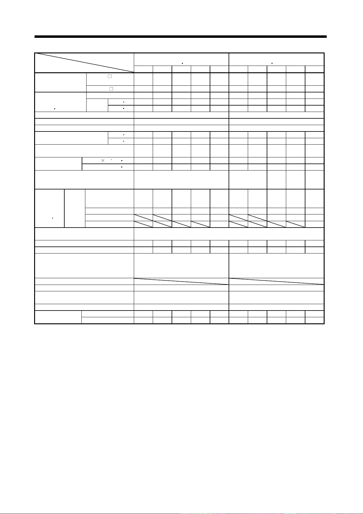
5. SPECIFICATIONS
Servo Motor
Item
Applicable servo
amplifier/drive unit
Continuous
running duty
(Note 1
Rated speed (Note 1) [r/min] 3000 3000
Maximum speed [r/min] 4500 4500
Instantaneous permissible speed [r/min] 5175 5175
Maximum torque
Power rate at continuous rated torque
Inertia moment
(Note 3)
Recommended ratio of load inertia moment to
servo motor shaft inertia moment (Note 2)
Regenerative
brake duty
[times/min]
(Note 4
Power supply capacity
Rated current [A] 0.85 0.85 1.5 2.8 5.1 0.83 0.71 1.1 2.3 5.8
Maximum current [A] 2.6 2.6 5 9 18 2.5 2.2 3.4 6.9 18.6
Speed/position detector
Accessories
Insulation class Class B Class B
Structure
Environmental conditions (Note 7) Refer to section 2.1 Refer to section 2.1
Mass (Note 3)
11)
MR-J2S
series
15)
MR-J2S- A/B/CP/
CL
MR-J2MRated output [kW] 0.05 0.1 0.2 0.4 0.75 0.05 0.1 0.2 0.4 0.75
Rated
torque
J[104kg m2] 0.019 0.03 0.088 0.143 0.6 0.053 0.084 0.260 0.460 1.51
2
WK
Servo amplifier's
built-in regenerative
resistor
MR-RB032(30W) (Note 5) (Note 5) (Note 5) 3000 600 (Note 5) (Note 5) (Note 5) 660 280
MR-RB12(100W) (Note 5) (Note5) 2400 (Note 5) 2200 940
MR-RB32(300W)
DU 10 10 20 40 70 10 10 20 40 70
[N m] 0.16 0.32 0.64 1.3 2.4 0.16 0.32 0.64 1.3 2.4
in] 22.7 45.3 90.7 184 340 22.7 45.3 90.7 184 340
[oz
[N m] 0.48 0.95 1.9 3.8 7.2 0.48 0.95 1.9 3.8 7.2
[oz
in] 68.0 135 269 538 1020 68.0 135 269 538 1020
[kW/s]
[oz in2] 0.104 0.16 0.48 0.78 3.28 0.29 0.459 1.422 2.515 8.26
[kg] 0.4 0.53 0.99 1.45 3.0 0.40 0.53 0.99 1.45 3.0
[lb] 0.88 1.17 2.18 3.20 6.61 0.882 1.168 2.18 3.20 6.61
(ultra low inertia
053 13 23 43 73 053 13 23 43 73
10 10 20 40 70 10 10 20 40 70
13.47 34.13 46.02 116.55 94 .43 4.78 12.1 15.8 36 .7 37. 7
(Note 5) (Note 5) (Note 5) 1010 400 (Note 5) (Note 5) (Note 5) 220 190
Refer to "Power supply equipment capacity and generated loss of servo amplifiers"
in Servo Amplifier Instruction Manual.
Encoder common to absolute position
and incremental detection systems
(Resolution per servo motor 1 rotation :
(protection type: IP55 (Note 6,12))
HC-MFS Series
small capacity)
30 times or less
131072 pulse/rev)
Totally-enclosed, self-cooled
15 times or
(Note5) 2800
Encoder common to absolute position
and incremental detection systems
(Resolution per servo motor 1 rotation :
(protection type: IP55 (Note 6,12))
HC-KFS Series
(low inertia small capacity)
24
less
Totally-enclosed, self-cooled
times
or less
131072 pulse/rev)
22
times
or less
15
times
or less
5 - 9
Page 77

5. SPECIFICATIONS
Servo Motor
Item
Applicable servo
amplifier/drive unit
Continuous
running duty
(Note 1
Rated speed (Note 1) [r/min] 1000 2000
Maximum speed [r/min] 1500 1200 3000 2500 2000
Instantaneous permissible speed [r/min] 1725 1380 3450 2875 2300
Maximum torque
Power rate at continuous rated torque
(Note 3)
Recommended ratio of load inertia moment to
servo motor shaft inertia moment (Note 2)
Regenerative
brake duty
[times/min]
(Note 4
Power supply capacity Refer to "Power supply equipment capacity and generated loss of servo amplifiers"
Rated current [A] 5.1 7.1 9.6 16 3.2 6 9 11 17 26 35
Maximum current [A] 15.3 21.3 28.8 48 9.6 18 27 33 51 84 105
Speed/position detector
Accessories Oil seal Oil seal
Insulation class Class F Class F
Structure
Environmental conditions (Note 7) Refer to section 2.1 Refer to section 2.1
Mass (Note 3)
11)
15)
MR-J2S- A/B/CP/
CL
Rated output [kW] 0.85 1.2 2.0 3.0 0.5 1.0 1.5 2.0 3.5 5.0 7.0
[N m] 8.12 11.5 19.1 28.6 2.39 4.78 7.16 9.55 16.7 23.9 33.4
[oz
[N m] 24.4 34.4 57.3 85.9 7.16 14.4 21.6 28.5 50.1 71.6 100.0
[oz
[kW/s]
[oz in2] 109 232 448 552 36.1 74.9 109 232 448 552 875
[kg] 9.0 12 19 23 5.0 7.0 9.0 12.0 19.0 23 32
MR-J2S
series
Rated
torque
J[104kg m2] 20.0 42.5 82 101 6.6 13.7 20.0 42.5 82.0 101 160Inertia moment
2
WK
Servo amplifier's
built-in regenerative
resistor
MR-RB032(30W) 220 165 80
MR-RB12(100W) 740 560 270
MR-RB32(300W) 2220 810
MR-RB30(300W) 730 330 250 408 192 95 90
MR-RB50(500W) 1216 550 430 680 320 158 150
MR-RB31(300W) 57
MR-RB51(500W) 95
HC-SFS1000r/min Series
(200V-compatible, middle
inertia, middle capacity)
81 121 201 301 52 102 152 202 352 502 702
100 200 200 350 60 100 200 200 350 500 700
in] 1151 1630 2707 4053 339 677 1015 1353 2367 3387 4733
in] 3458 4875 8120 12173 1015 2041 3061 4039 7100 10146 14171
32.9 30.9 44.5 81.3 8.7 16.7 25.6 21.5 34.1 56.5 69.7
15 times or less 15 times or less
140 240 100 84 56 54 136 64 31 39 32
in Servo Amplifier Instruction Manual.
Encoder common to absolute
position and incremental
detection systems (Resolution
per servo motor 1 rotation:
131072 pulse/rev)
Totally-enclosed, self-cooled
(protection type: IP65)
[lb] 19.8 26.5 41.9 50.7 11.0 15.4 19.8 26.5 41.9 50.7 70.5
(200V-compatible, middle inertia, middle capacity)
Encoder common to absolute position and incremental
detection systems (Resolution per servo motor 1
HC-SFS 2000r/min Series
rotation: 131072 pulse/rev)
Totally-enclosed, self-cooled
(protection type: IP65(Note 12))
5 - 10
Page 78

5. SPECIFICATIONS
Servo Motor
Item
Applicable servo
amplifier
Continuous
running duty
(Note 1
Rated speed (Note 1) [r/min]
Maximum speed [r/min] 3000
Instantaneous permissible speed [r/min] 3450
Maximum torque
Power rate at continuous rated torque
Inertia moment
(Note 3)
Recommended ratio of load inertia moment
to servo motor shaft inertia moment (Note 2)
Regenerative
brake duty
[times/min]
(Note 4
Power supply capacity
Rated current [A] 3.2 5.3 8.6 10.4 16.4
Maximum current [A] 9.6 15.9 25.8 31.2 49.2
Speed/position detector
Accessories Oil seal
Insulation class Class F
Structure
Environmental conditions (Note 7)
Mass (Note 3)
11)
15)
MR-J2S- A/B/CP/
CL
Rated output [kW] 0.5 1.0 1.5 2.0 3.5
Rated
torque
J[104kg m2]
WK
Servo amplifier's
built-in regenerative
resistor
MR-J2S
series
MR-RB032(30W) 73 36
MR-RB12(100W) 250 120
MR-RB32(300W) 360
MR-RB30(300W) 250 70 42
MR-RB50(500W) 410 110 70
2
[N m] 1.59 3.18 4.78 6.37 11.1
in] 225 451 677 903 1573
[oz
[N m] 4.77 9.55 14.3 19.1 33.4
[oz
in] 676 1353 2026 2707 4733
[kW/s]
[oz in2] 36.1 74.9 109.3 232.4 448.3
[kg] 5.0 7.0 9.0 12 19
[lb] 11.0 15.4 19.8 26.5 41.9
HC-SFS 3000r/min Series
(200V-compatible,
middle inertia
53 103 153 203 353
60 100 200 200 350
3.8 7.4 11.4 9.5 15.1
6.6 13.7 20.0 42.5 82.0
25 24 82 24 14
Refer to "Power supply equipment
capacity and generated loss of servo
amplifiers" in Servo Amplifier
Instruction Manual.
Encoder common to absolute position
and incremental detection systems
(Resolution per servo motor 1 rotation :
131072 pulse/rev)
Totally-enclosed, self-cooled
(protection type: IP65)
Refer to section 2.1
middle capacity)
3000
15 times or less
5 - 11
Page 79

5. SPECIFICATIONS
Servo Motor
Item
Applicable servo
amplifier
Continuous
running duty
(Note 1
Rated speed (Note 1) [r/min] 2000
Maximum speed [r/min] 3000 2500 2000
Instantaneous permissible speed [r/min] 3450 2875 2300
Maximum torque
Power rate at continuous rated torque
Inertia moment
(Note 3)
Recommended ratio of load inertia
moment to servo motor shaft inertia
moment (Note2)
Regenerative
brake duty
[times/min]
(Note 4)
Power supply capacity
Rated current [A] 1.5 2.8 4.4 5.4 8.6 14 17
Maximum current [A] 4.5 8.4 13.2 16.2 25.8 42 51
Speed/position detector
Accessories Oil seal
Insulation class Class F
Structure Totally-enclosed, self-cooled(protection type: IP65 (Note 12))
Environmental conditions (Note 7) Refer to section 2.1
Mass (Note 3)
11)
MR-J2S-
Rated output [kW] 0.5 1.0 1.5 2.0 3.5 5.0 7.0
Rated
torque
J [ 104kg m2] 6.6 13.7 20.0 42.5 82.0 101 160
WK
Servo amplifier’s
built-in regenerative
resistor
MR-RB1L-4(100W) 560
MR-J2S
Series
MR-RB3M-4(300W) 810
MR-RB3H-4(300W) 408 192
MR-RB5H-4(500W) 680 320
MR-RB3G-4(300W) 95 90
MR-RB5G-4(500W) 158 150
MR-RB34-4(300W) 57
MR-RB54-4(500W) 95
A4 60 100 200 350 500 700
[N m] 2.39 4.78 7.16 9.55 16.7 23.9 33.4
in] 338.5 676.9 1013.9 1352.4 2364.9 3384.5 4729.9
[oz
[N m] 7.16 14.4 21.6 28.5 50.1 71.6 100.0
[oz
in] 1013.9 2039.2 3058.8 4036 7094.8 10139.4 14161.2
[kW/s]
2
[oz in2] 36.1 74.9 109.3 232.4 448.3 552.2 874.8
[kg] 5.0 7.0 9.0 12.0 19.0 23 32
[lb] 11 15.4 19.8 26.5 41.9 50.7 70.5
HC-SFS Series(400VAC-compatible, middle inertia middle capacity)
524 1024 1524 2024 3524 5024 7024
8.7 16.7 25.6 21.5 34.1 56.5 69.7
15 times or less
56 54 136 64 31 39 32
Refer to “Power supply equipment capacity and generated loss of servo
amplifiers” in Servo Amplifier Instruction Manual.
Encoder common to absolute position and incremental detection systems
(Resolution per servo motor 1 rotation: 131072 pulse/rev)
5 - 12
Page 80

5. SPECIFICATIONS
Servo Motor
Item
Applicable servo
amplifier
Continuous
running duty
(Note 1
Rated speed (Note 1) [r/min]
Maximum speed [r/min] 4500
Instantaneous permissible speed [r/min] 5175
Maximum torque
Power rate at continuous rated torque
Inertia moment
(Note 3)
Recommended ratio of load inertia moment
to servo motor shaft inertia moment (Note 2)
Regenerative
brake duty
[times/min]
(Note 4)
Power supply capacity
Rated current [A] 6.1 8.8 14 23 28
Maximum current [A] 18.4 23.4 37 58 70
Speed/position detector
Accessories Oil seal
Insulation class Class F
Structure
Environmental conditions (Note 7)
Mass (Note 3)
11)
MR-J2S- A/B/CP/
CL
Rated output [kW] 1.0 1.5 2.0 3.5 5.0
Rated
torque
J[104kg m2]
WK
Servo amplifier's
MR-J2S
series
built-in regenerative
resistor
MR-RB30(300W) 3270 2580 2130 401 288
MR-RB50(500W) 5450 4300 3550 669 479
2
[N m] 3.18 4.78 6.37 11.1 15.9
[oz
in] 450 677 902 1572 2252
[N m] 7.95 11.9 15.9 27.9 39.7
[oz
in] 1126 1686 2253 3954 5626
[kW/s]
[oz in2] 8.2 10.4 12.6 47.0 65.6
[kg] 3.9 5.0 6.2 12.0 17.0
[lb] 8.6 11.0 13.7 26.5 37.5
(ultra low inertia
103 153 203 353 503
200 200 350 500 500
67.4 120 176 150 211
1.5 1.9 2.3 8.6 12.0
1090 860 710 174 125
Refer to "Power supply equipment
capacity and generated loss of servo
Encoder common to absolute position
and incremental detection systems
(Resolution per servo motor 1 rotation:
(protection type: IP65 (Note 12))
HC-RFS Series
middle capacity)
3000
5 times or less
amplifiers" in Servo Amplifier
Instruction Manual.
131072 pulse/rev)
Totally-enclosed, self-cooled
Refer to section 2.1
5 - 13
Page 81
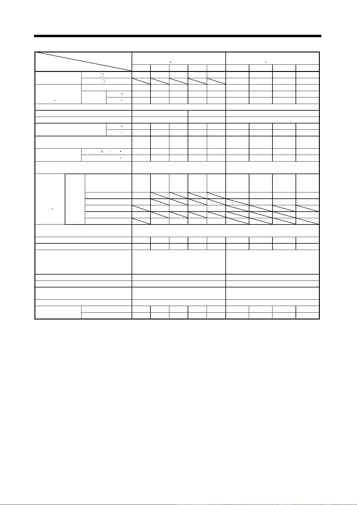
5. SPECIFICATIONS
Item
Applicable servo
amplifier/drive unit
Continuous
running duty
(Note 1
11)
Servo Motor
HC-UFS 2000r/min Series
(flat type
middle capacity)
72 152 202 352 502 13 23 43 73
MR-J2S A/B/CP/CL 70 200 350 500 500 10 20 40 70
MR-J2M
DU 10 20 40 70
Rated output [kW] 0.75 1.5 2.0 3.5 5.0 0.1 0.2 0.4 0.75
Rated
torque
[N m] 3.58 7.16 9.55 16.7 23.9 0.32 0.64 1.3 2.4
in] 507 1015 1353 2367 3387 45 91 184 340
[oz
HC-UFS 3000r/min Series
(flat type small capacity)
Rated speed (Note 1) [r/min] 2000 3000
Maximum speed [r/min] 3000 2500 4500
Instantaneous permissible speed [r/min] 3450 2875 5175
Maximum torque
Power rate at continuous rated torque
Inertia moment
(Note 3)
J[104kg m2] 10.4 22.1 38.2 76.5 115 0.066 0.241 0.365 5.90
2
WK
Recommended ratio of load inertia moment
to servo motor shaft inertia moment (Note 2)
[N m] 10.7 21.6 28.5 50.1 71.6 0.95 1.9 3.8 7.2
[oz
in] 1516 3061 4039 7100 10146 135 269 538 1020
[kW/s]
12.3 23.2 23.9 36.5 49.6 15.5 19.2 47.7 9.76
[oz in2] 56.9 120.8 208.9 418.3 628.8 0.4 1.3 2.0 32.3
15 times or less 15 times or less
Servo amplifier's
53 124 68 44 31 (Note5) (Note5) 410 41
Regenerative
brake duty
[times/min]
(Note 4
15)
MR-J2S
Series
built-in regenerative
resistor
MR-RB032(30W) 79 (Note5) (Note5) 1230 62
MR-RB12(100W) 264 (Note5) 4100 206
MR-RB30(300W) 372 203 102 72
MR-RB32(300W) 791 618
620 338 169 119
Power supply capacity
MR-RB50(500W)
Refer to "Power supply equipment capacity and generated loss of servo amplifiers"
in Servo Amplifier Instruction Manual.
Rated current [A] 5.4 9.7 14 23 28 0.76 1.5 2.8 4.3
Maximum current [A] 16.2 29.1 42 69 84 2.5 4.95 9.24 12.9
Speed/position detector
Encoder common to absolute position and
incremental detection systems (Resolution
per servo motor 1 rotation : 131072
pulse/rev)
Encoder common to absolute position and
incremental detection systems (Resolution
per servo motor 1 rotation : 131072
pulse/rev)
Accessories Oil seal Oil seal
Insulation class Class F Class B
Structure
Totally-enclosed, self-cooled
(protection type: IP65)
Totally-enclosed, self-cooled
(protection type: IP65(Note9))
Environmental conditions (Note 7) Refer to section 2.1 Refer to section 2.1
Mass (Note 3)
[kg] 8.0 11.0 16.0 20.0 24.0 0.8 1.5 1.7 5.0
[lb]
17.6 24.3 35.3 44.1 52.9 1.8 3.3 3.7 11.0
5 - 14
Page 82

5. SPECIFICATIONS
HA-LFS 1000r/min Series (200VAC-compatible, low inertia middle large capacity)Servo Motor
Item
Applicable servo
amplifier
MR-J2S-
A/B
Compatible converter unit MR-HP30KA
Continuous
running duty
(Note 1
11)
Rated output [kW] 6 8 12 15 20 25 30
Rated
torque
[N m] 57.3 76.4 115 143 191 239 286 353
[oz
in] 8114 10819 16285 20251 27048 33845 40501 49989
Rated speed (Note 1) [r/min] 1000
Maximum speed [r/min] 1200
Instantaneous permissible speed [r/min] 1380
Maximum torque
[N m] 172 229 344 415 477 597 716 883
[oz
in] 24357 32429 48715 58769 67549 84542 101394 125044
Power rate at continuous rated torque
[kW/s]
Inertia moment
(Note 3)
J[104kg m2] 105 220 295 550 650 1080 1310 1870
WK
2
[oz in2] 574.1 1202.8 1612.9 3007.1 3553.8 5904.8 7162.4 10224.1
Recommended ratio of load inertia moment
to servo motor shaft inertia moment
(Note 2)
Servo amplifier’s
built-in regenerative
resistor
MR-RB31(300W) 278
Regenerative
brake duty
MR-RB51(500W) 464
MR-RB65(800W)
[times/min]
(Note 4)
MR-RB66(1300W)
MR-RB67(1300W)
MR-RB139(1300W) 97 68
MR-RB137(3900W) 290 203
Power supply capacity
Rated current [A] 34 42 61 83 118 118 154 188
Maximum current [A] 102 126 183 249 295 295 385 470
Speed/position detector
Voltage frequency
Power
consumption
[W]
Cooling fan
Power
supply
Rated current [A]
Thermal
protector
Maximum rated 125VAC/DC, 3A or 250VAC/DC, 2A
Minimum rated 6VAC/DC, 0.15A
Accessories Oil seal
Insulation class Class F
Structure Totally-enclosed, force-cooled (protection type: IP44)
Environmental conditions (Note 7) Refer to section 2.1
Mass (Note 3)
[kg] 55 95 115 160 180 230 250 335
[lb] 121.3 209.4 253.5 352.7 396.8 507.1 551.6 738.5
601
(Note 13)
700A-U058
700B-U058
700CP-U058
700CL-U058
801 12K1 15K1 20K1 25K1 30K1 37K1
37KA11KA
11KB
15KA
15KB
22KA
22KB
30KA
30KB
U039
37KB-
U039
(75% ED)
313 265 445 373 561 528 626 668
10 times or less
158
354
(Note 10
14)
354
(Note 14)
264
(Note 10
14)
264
(Note 14)
230
(Note 10
14)
195
(Note 10
14)
117
(Note 10
14)
230
(Note 14)
195
(Note 14)
117
(Note 14)
Refer to “Power supply equipment capacity and generated loss of servo
amplifiers” in Servo Amplifier Instruction Manual.
Encoder common to absolute position and incremental detection systems
(Resolution per servo motor 1 rotation: 131072 pulse/rev)
Three-phase
200 to 220
VAC 50Hz,
One-phase
Three-phase 200 to 230VAC 50Hz/60Hz
200 to 230
VAC 60Hz
42(50Hz)/
54(60Hz)
0.21(50Hz)/
0.25(60Hz)
62(50Hz)/
76(60Hz)
0.18(50Hz)/
0.17(60Hz)
65(50Hz)/
85(60Hz)
0.20(50Hz)/
0.22(60Hz)
120(50Hz)/
175(60Hz)
0.65(50Hz)/
0.80(60Hz)
37
5 - 15
Page 83

5. SPECIFICATIONS
HA-LFS 1500r/min Series (200VAC-compatible, low inertia middle large capacity)Servo Motor
Item
Applicable servo
amplifier
MR-J2S-
(Note 13)
700A-U058
700B-U058
700CP-U059
700CL-U059
Compatible converter unit MR-HP30KA
701M
Continuous
running duty
(Note 1
11)
Rated output [kW] 7 11 15 22 30
Rated
torque
[N m] 44.6 70.0 95.5 140 191 236
[oz
in] 6315.9 9912.9 13524 19825.7 27047.9 33420.5
Rated speed (Note 1) [r/min] 1500
Maximum speed [r/min] 2000
Instantaneous permissible speed [r/min] 2300
Maximum torque
Power rate at continuous rated torque
Inertia moment
(Note 3)
J[104kg m2] 105 220 295 550 650 1080
2
WK
[N m] 134 210 286 350 477 589
[oz
in] 18976 29738.6 40501.1 49564.3 67549.1 83409.6
[kW/s]
189 223 309 357 561 514
[oz in2] 574.1 1202.8 1612.9 3007.1 3553.8 5904.8
Recommended ratio if load inertia moment
to servo motor shaft inertia moment
(Note 2)
Servo amplifier’s
built-in regenerative
70
resistor
MR-RB31(300W) 124
Regenerative
brake duty
MR-RB51(500W) 206
MR-RB65(800W)
[times/min]
(Note 4)
MR-RB66(1300W)
MR-RB67(1300W)
MR-RB139(1300W) 87 52
MR-RB137(3900W) 260 156
Power supply capacity
Refer to “Power supply equipment capacity and generated loss of servo
amplifiers” in Servo Amplifier Instruction Manual.
Rated current [A] 37 65 87 126 174 202
Maximum current [A] 111 195 261 315 435 505
Speed/position detector
Encoder common to absolute position and incremental detection systems
One-phase
200 to 220
[W]
VAC 50Hz,
One-phase
200 to 230
VAC 60Hz
42(50Hz)/
54(60Hz)
0.21(50Hz)/
0.25(60Hz)
cooling fan
Thermal
protector
Power
Voltage frequency
supply
Power
consumption
Rated current [A]
Maximum rated 125VAC/DC, 3A or 250VAC/DC, 2A
Minimum rated 6VAC/DC, 0.15A
Accessories Oil seal
Insulation class Class F
Structure Totally-enclosed, force-cooled (protection type: IP44)
Environmental conditions (Note 7) Refer to section 2.1
Mass (Note 3)
[kg] 55 95 115 160 180 230
[lb] 121.3 209.4 253.5 352.7 396.8 507.1
11K1M 15K1M 22K1M 30K1M 37K1M
11KA
11KB
15KA
15KB
22KA
22KB
30KA
30KB
10 times or less
158
(Note 10
14)
191
(Note 10
14)
102
(Note 10
14)
158
(Note 14)
191
(Note 14)
102
(Note 14)
(Resolution per servo motor 1 rotation: 131072 pulse/rev)
Three-phase 200 to 230VAC 50Hz/60Hz
62(50Hz)/
76(60Hz)
0.18(50Hz)/
0.17(60Hz)
65(50Hz)/
85(60Hz)
0.20(50Hz)/
0.22(60Hz)
37KA-U042
37KB-U042
(75% ED)
120(50Hz)/
175(60Hz)
0.65(50Hz)/
0.80(60Hz)
37
5 - 16
Page 84
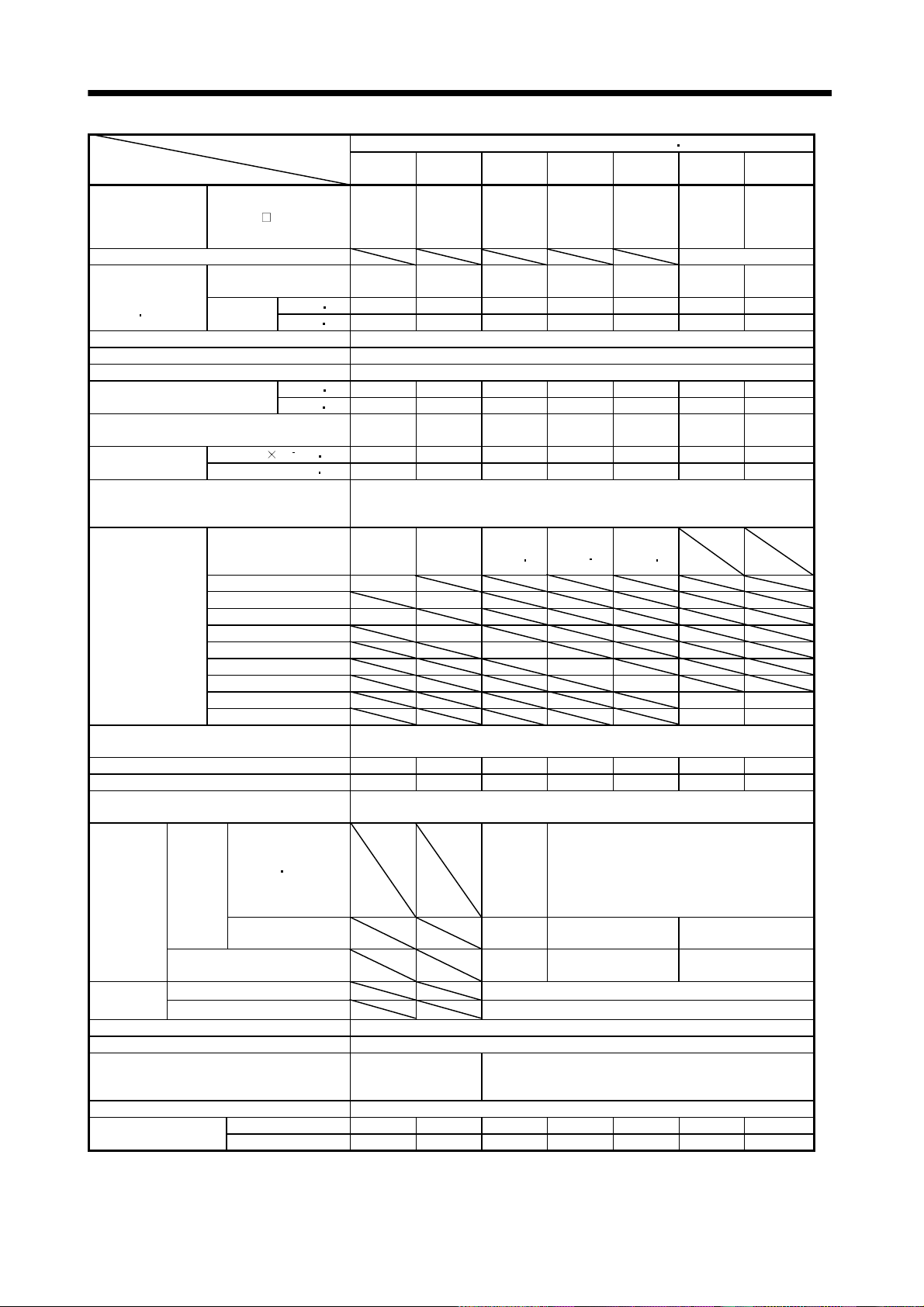
5. SPECIFICATIONS
HA-LFS 2000r/min Series (200VAC-compatible, low inertia middle large capacity)Servo Motor
Item
(Note 13)
500A
502
Applicable servo
amplifier
MR-J2S-
500B
500CP
500CL
Compatible converter unit MR-HP30KA
Continuous
running duty
(Note 1
11)
Rated output
Rated
torque
[kW] 5.0 7.0 11 15 22 30
[N m] 23.9 33.4 52.5 71.6 105 143 177
[oz
in] 3384.5 4729.9 7434.6 10139.4 14869.3 20250.6 25065.4
Rated speed (Note 1) [r/min] 2000
Maximum speed [r/min] 2000
Instantaneous permissible speed [r/min] 2300
Maximum torque
Power rate at continuous rated torque
Inertia moment
(Note 3)
J[104kg m2] 74.0 94.2 105 220 295 550 650
2
WK
[N m] 71.6 100 158 215 263 358 442
[oz
in] 10139.4 14161.2 22374.7 30446.6 37244 50697.2 62592.6
[kW/s]
77.2 118 263 233 374 373 480
[oz in2] 404.6 515 574.1 1202.8 1612.9 3007.1 3553.8
Recommended ratio of load inertia moment
to servo motor shaft inertia moment
(Note 2)
Servo amplifier’s
built-in regenerative
50 50
resistor
MR-RB30(300W) 120
Regenerative
brake duty
[times/min]
(Note 4)
MR-RB31(300W) 95
MR-RB50(500W) 200
MR-RB51(500W) 160
MR-RB65(800W) 186(Not e 14)
MR-RB66(1300W) 144(Not e 14)
MR-RB67(1300W) 107(Not e 14)
MR-RB139(1300W) 58 49
MR-RB137(3900W) 174 147
Power supply capacity
Refer to “Power supply equipment capacity and generated loss of servo
amplifiers” in Servo Amplifier Instruction Manual.
Rated current [A] 25 34 63 77 112 166 204
Maximum current [A] 75 102 189 231 280 415 510
Speed/position detector
Power
Cooling fan
supply
Voltage frequency
Power
consumption
[W]
Encoder common to absolute position and incremental detection systems
Rated current [A]
Thermal
protector
Maximum rated 125VAC/DC, 3A or 250VAC/DC, 2A
Minimum rated 6VAC/DC, 0.15A
Accessories Oil seal
Insulation class Class F
Totally-enclosed,
Structure
self-cooled
(protection: IP65)
Environmental conditions (Note 7) Refer to section 2.1
Mass (Note 3)
[kg] 28 35 55 95 115 160 180
[lb] 61.7 77.2 121.3 209.4 253.5 352.7 396.8
702
(Note 13)
11K2 15K2 22K2 30K2 37K2
700A
700B
700CP
11KA
11KB
15KA
15KB
22KA
22KB
30KA
30KB
700CL
10 times or less
186
(Note 10 14)
144
(Note 10 14)
107
(Note 10 14)
(Resolution per servo motor 1 rotation: 131072 pulse/rev)
One-phase
200 to 220
VAC 50Hz,
One-phase
Three-phase 200 to 230VAC 50Hz/60Hz
200 to 230
VAC 60Hz
42(50Hz)/
54(60Hz)
0.21(50Hz)/
0.25(60Hz)
62(50Hz)/
76(60Hz)
0.18(50Hz)/
0.17(60Hz)
65(50Hz)/
85(60Hz)
0.20(50Hz)/
0.22(60Hz)
Totally-enclosed, force-cooled (protection: IP44)
37KA
37KB
(75% ED)
37
5 - 17
Page 85

5. SPECIFICATIONS
HA-LFS 1000r/min Series (400VAC-compatible, low inertia large capacity)Servo Motor
Item
Applicable
servo
MR-J2S-
amplifier
Compatible converter unit MR-HP55KA4
Continuous
running duty
(Note 1
11)
Rated output [kW] 6 8 12 15 20 25 30 37
Rated
torque
[N m] 57.3 76.4 115 143 191 239 286 353
[oz
Rated speed (Note 1) [r/min] 1000
Maximum speed [r/min] 1200
Instantaneous permissible speed [r/min] 1380
Maximum torque
[N m] 172 229 344 415 477 597 716 883
[oz
Power rate at continuous rated torque
[kW/s]
Inertia moment
(Note 3)
J[104kg m2] 105 220 295 550 650 1080 1310 1870
WK
2
[oz in2] 574.1 1202.8 1612.9 3007.1 3553.8 5904.8 7162.4 10224.1
Recommended ratio of load inertia
moment to servo motor shaft inertia
moment (Note 2)
Servo amplifier's
supplied regenerative
resistor
MR-RB34-4(300W) 278
Regenerative
brake duty
MR-RB54-4(500W) 464
MR-RB6B-4(800W)
[times/min]
(Note 4)
MR-RB60-4(1300W)
MR-RB6K-4(1300W)
MR-RB136-4(1300W) 118 97 68
MR-RB138-4(3900W) 354 290 203
Power supply capacity
Rated current [A] 17 20 30 40 55 70 77 95
Maximum current [A] 51 63 93 126 148 175 193 235
Speed/position detector
Power
Voltage frequency
supply
Cooling fan
Power
consumption
Rated current [A]
Thermal
protector
Maximum rated 125VAC/DC, 3A or 250VAC/DC, 2A
Minimum rated 6VAC/DC, 0.15A
Accessories Oil seal
Insulation class Class F
Structure Totally-enclosed, force-cooled (protection: IP44)
Environmental conditions (Note 7) Refer to section 2.1
Mass (Note 3)
6014 8014 12K14 15K14 20K14 25K14 30K14 37K14
700A4-
U071
700B4-
11KA4
11KB4
11KA4
11KB4
15KA4
15KB4
22KA4
22KB4
30KA4
30KB4
30KA4
30KB4
37KA4
37KB4
U071
in] 8114.4 10819.1 16285.4 20250.56 27047.95 33845.34 40501.11 49989.14
in] 24357.3 32429.21 48714.63 58769.1 67549.06 84542.54 101394.4 125043.65
313 265 445 373 561 528 626 668
10 times or less
158
354
(Note 10
14)
354
(Note 14)
264
(Note 10
14)
264
(Note 14)
230
(Note 10
14)
195
(Note 10
14)
230
(Note 14)
195
(Note 14)
Refer to “Power supply equipment capacity and generated loss of servo amplifiers” in
Servo Amplifier Instruction Manual.
Encoder common to absolute position and incremental detection systems
(Resolution per servo motor 1 rotation: 131072 pulse/rev)
One-phase
200 to
220VAC/
50Hz,
One-phase
200 to
Three-phase 380 to
440VAC 50Hz
Three-phase 380 to
480VAC 60Hz
Three-phase 380 to 460VAC 50Hz
Three-phase 380 to 480VAC 60Hz
230VAC/
60Hz
[W]
42 (50Hz)/
54 (60Hz)
62 (50Hz)/
76 (60Hz)
65 (50Hz)/
85 (60Hz)
110 (50Hz)/
150 (60Hz)
0.21
(50Hz)/
0.25
0.14 (50Hz)/
0.11 (60Hz)
0.12 (50Hz)/
0.14 (60Hz)
0.20 (50Hz)/
0.22 (60Hz)
(60Hz)
[kg] 55 95 115 160 180 230 250 335
[lb] 121.3 209.4 209.43 352.7 396.8 507 551.2 738.5
5 - 18
Page 86
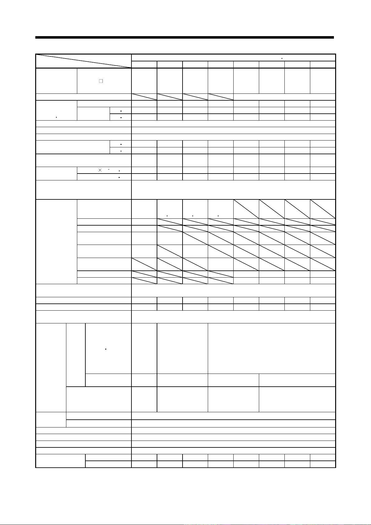
5. SPECIFICATIONS
HA-LFS 1500r/min Series (400VAC-compatible, low inertia large capacity)Servo Motor
Item
Applicable servo
amplifier
MR-J2S-
Compatible converter unit MR-HP55KA4
Continuous
running duty
(Note 1
11)
Rated output[kW]7 11152230374550
Rated
torque
[N m] 44.6 70.0 95.5 140 191 236 286 318
[oz
Rated speed (Note 1) [r/min] 1500
Maximum speed [r/min] 2000
Instantaneous permissible speed [r/min] 2300
Maximum torque
[N m] 134 210 286 350 477 589 716 796
[oz
Power rate at continuous rated torque
[kW/s]
Inertia moment
(Note 3)
J[104kg m2] 105 220 295 550 650 1080 1310 1870
WK
2
[oz in2] 574.1 1202.8 1612.9 3007.1 3553.8 5904.8 7162.4 10224.1
Recommended ratio of load inertia
moment to servo motor shaft inertia
moment (Note 2)
Servo amplifier's
supplied regenerative
resistor
MR-RB34-4(300W) 124
Regenerative
brake duty
MR-RB54-4(500W) 206
MR-RB6B-4(800W) 124
[times/min]
(Note 4)
MR-RB60-4(1300W) 206
MR-RB6K-4(1300W)
MR-RB136-4(1300W) 87 52 43 30
MR-RB138-4(3900W) 260 156 129 90
Power supply capacity
Rated current [A] 18 31 41 63 87 101 128 143
Maximum current [A] 54 99 132 158 218 253 320 358
Speed/position detector
Voltage frequency
Power
supply
Cooling fan
Power
consumption
Rated current [A]
Thermal
protector
Maximum rated 125VAC/DC, 3A or 250VAC/DC, 2A
Minimum rated 6VAC/DC, 0.15A
Accessories Oil seal
Insulation class Class F
Structure Totally-enclosed, force-cooled (protection: IP44)
Environmental conditions (Note 7) Refer to section 2.1
Mass (Note 3)
701M4 11K1M4 15K1M4 22K1M4 30K1M4 37K1M4 45K1M4 50K1M4
700A4-
U073
700B4-
11KA4
11KB4
15KA4
15KB4
22KA4
22KB4
30KA4
30KB4
37KA4
37KB4
45KA4
45KB4
55KA4
55KB4
U073
in] 6315.9 9912.86 13523.97 19825.72 27047.95 33420.5 40501.11 45032.71
in] 18976 29738.6 40501.1 49564.3 67549.1 83409.6 101394.3 112723.4
189 223 309 357 561 514 626 542
10 times or less
70
158
(Note 10
14)
191
(Note 10
14)
102
(Note 10
14)
158
(Note 14)
191
(Note 14)
102
(Note 14)
Refer to “Power supply equipment capacity and generated loss of servo amplifiers” in
Servo Amplifier Instruction Manual.
Encoder common to absolute position and incremental detection systems
(Resolution per servo motor 1 rotation: 131072 pulse/rev)
One-phase
200 to
220VAC/
50Hz,
One-phase
200 to
Three-phase 380 to
440VAC 50Hz
Three-phase 380 to
480VAC 60Hz
Three-phase 380 to 460VAC 50Hz
Three-phase 380 to 480VAC 60Hz
230VAC/
60Hz
[W]
42 (50Hz)/
54 (60Hz)
62 (50Hz)/
76 (60Hz)
65 (50Hz)/
85 (60Hz)
110 (50Hz)/
150 (60Hz)
0.21
(50Hz)/
0.25
0.14 (50Hz)/
0.11 (60Hz)
0.12 (50Hz)/
0.14 (60Hz)
0.20 (50Hz)/
0.22 (60Hz)
(60Hz)
[kg] 55 95 115 160 180 230 250 335
[lb] 121.3 209.4 253.5 352.7 396.8 507.1 551.2 738.5
5 - 19
Page 87

5. SPECIFICATIONS
HA-LFS 2000r/min Series (400VAC-compatible, low inertia large capacity)Servo Motor
Item
Applicable servo
amplifier
MR-J2S-
A4/B4 11K 15K 22K 30K 37K 45K 55K
Compatible converter unit MR-HP55KA4
Continuous
running duty
(Note 1
11)
Rated output [kW] 11 15 22 30 37 45 55
Rated
torque
[N m] 52.5 71.6 105 143 177 215 263
in] 7434.6 10139.4 14869.3 20250.6 25065.4 30446.6 37244
[oz
Rated speed (Note 1) [r/min] 2000
Maximum speed [r/min] 2000
Instantaneous permissible speed [r/min] 2300
Maximum torque
[N m] 158 215 263 358 442 537 657
[oz
in] 22374.7 30446.6 37244 506972 62592.6 76045.8 93039.3
Power rate at continuous rated torque
[kW/s]
Inertia moment
(Note 3)
J[104kg m2] 105 220 295 550 650 1080 1310
WK
2
[oz in2] 574.1 1202.8 1612.9 3007.1 3553.8 5904.8 7162.4
Recommended ratio of load inertia moment
to servo motor shaft inertia moment
(Note 2)
Servo amplifier's
supplied regenerative
Regenerative
brake duty
[times/min]
(Note 4)
resistor
MR-RB6B-4(800W) 186 (Note14)
MR-RB60-4(1300W) 144(Note 14)
MR-RB6K-4(1300W) 107(Note 14)
MR-RB136-4(1300W) 58 49 30 24
MR-RB138-4(3900W) 174 147 89 73
Power supply capacity
Rated current [A] 32 40 57 83 102 131 143
Maximum current [A] 96 120 171 208 255 328 358
Speed/position detector
Voltage frequency
Power
consumption
[W]
Cooling fan
Power
supply
Rated current [A]
Thermal
protector
Maximum rated 125VAC/DC, 3A or 250VAC/DC, 2A
Minimum rated 6VAC/DC, 0.15A
Accessories Absolute Encoder, oil seal
Insulation class Class F
Structure Totally-enclosed, force-cooled (protection: IP44)
Environmental conditions (Note 7) Refer to section 2.1
Mass (Note 3)
[kg] 55 95 115 160 180 230 250
[lb] 121.3 209.4 253.5 352.7 396.8 507.1 551.2
11K24 15K24 22K24 30K24 37K24 45K24 55K24
263 233 374 373 480 427 526
10 times or less
186
(Note 10
14)
144
(Note 10
14)
107
(Note 10
14)
Refer to “Power supply equipment capacity and generated loss of servo
amplifiers” in Servo Amplifier Instruction Manual.
Encoder common to absolute position and incremental detection systems
(Resolution per servo motor 1 rotation: 131072 pulse/rev)
One-phase 200
to
220VAC/50Hz,
One-phase 200
to
Three-phase 380 to
440VAC 50Hz
Three-phase 380 to
480VAC 60Hz
Three-phase 380 to 460VAC 50Hz
Three-phase 380 to 480VAC 60Hz
230VAC/60Hz
42 (50Hz)/
54 (60 Hz)
0.21 (50Hz)/
0.25 (60 Hz)
62 (50Hz)/
76 (60Hz)
0.14 (50Hz)/
0.11 (60Hz)
65 (50Hz)/
85 (60Hz)
0.12 (50Hz)/
0.14 (60Hz)
110 (50Hz)/
150 (60Hz)
0.20 (50Hz)/
0.22 (60Hz)
5 - 20
Page 88

5. SPECIFICATIONS
HC-LFS Series (low inertia middle capacity)Servo Motor
Item
Applicable servo
amplifier
Continuous
running duty
(Note 1
Rated speed (Note 1) [r/min] 2000
Maximum speed [r/min] 3000
Instantaneous permissible speed [r/min] 3450
Maximum torque
Power rate at continuous rated torque
Inertia moment
(Note 3)
Recommended ratio of load inertia moment
to servo motor shaft inertia moment
(Note 2)
Regenerative
brake duty
[times/min]
(Note 4
Power supply capacity
Rated current [A] 3.2 5.9 9.9 14 23
Maximum current [A] 9.6 18 30 42 69
Speed/position detector
Accessories Oil seal
Insulation class Class F
Structure Totally-enclosed, self-cooled (protection type: IP65)
Environmental conditions (Note 7) Refer to section 2.1
Mass (Note 3)
11)
15)
MR-J2S-
Rated output [kW] 0.5 1.0 1.5 2.0 3.0
Rated
torque
J[104kg m2] 3.2 4.6 6.4 22 36
WK
Servo amplifier’ built-in
regenerative resistor
MR-RB032(30W) 340 235
MR-RB12(100W) 1150 800
MR-RB30(300W) 1270 370 215
MR-RB32(300W) 2410
MR-RB50(500W) 2120 615 355
A/B/CP/CL 60 100 200 350 500
[N m] 2.39 4.78 7.16 9.55 14.3
in] 338.5 676.9 1013.9 1352.4 2025.1
[oz
[N m] 7.16 14.4 21.6 28.5 42.9
[oz
in] 1013.9 2039.2 3058.8 4036 6075.2
[kW/s]
2
[oz in2] 17.5 25.2 35 120.3 196.8
[kg] 6.5 8.0 10.0 21 28
[lb] 14.33 17.6 22 46.3 61.7
52 102 152 202 302
17.9 49.7 80.1 41.5 56.8
10 times or less
115 160 425 120 70
Refer to “Power supply equipment capacity and generated loss of servo
amplifiers” in Servo Amplifier Instruction Manual.
Encoder common to absolute position and incremental detection systems
(Resolution per servo motor 1 rotation: 131072 pulse/rev)
5 - 21
Page 89

5. SPECIFICATIONS
Note 1.When the power supply voltage drops, we cannot guarantee the output and rated speed.
2.If the load inertia moment ratio exceeds the indicated value, please consult us.
3.This ratio is the load inertia moment ratio to the inertia moment of the servo motor. If the load inertia moment ratio exceeds the
indicated value, please consult us. When the servo motor is equipped with reduction gear or electromagnetic brake, refer to the
corresponding outline dimension drawing. For the EN Standard- and UL/C-UL Standard-compliant models, please consult us.
4.The regenerative brake duty indicated is the permissible duty when the servo motor running without load at the rated speed is
decelerated to a stop. When a load is connected, the value in the table is multiplied by 1/(m
moment/motor inertia moment. At the speed higher than the rated, the permissible number of times is in inverse proportion to
the square of (running speed/rated speed). When the running speed varies frequently or when the regenerative mode continues
as in vertical feed, calculate regenerative heat generated during operation. Provisions must be made to keep this generated heat
below the permissible value.
5.If the effective torque is within the rated torque range, there are no restrictions on the regenerative duty.
6.Except for the shaft-through portion and connector end.
7.In the environment where the servo motor is exposed to oil mist, oil and/or water, the servo motor of the standard specifications
may not be usable. Contact us.
8.IP54 for the EN Standard-compliant model.
9.Except the connector section.
10.Values for use of the supplied regenerative brake unit (regenerative resistor) are indicated in the case of the 11k to 22kW servo
amplifiers. Values for use of the supplied regenerative brake unit (regenerative resistor).
11.80%ED at low noise.
80%ED: Indicates the condition in which operation time at read torque accounts for 80% and the other no-load time accounts for
20% in a single operation cycle.
1), where m load inertia
Torque
100%
12.When the servo motor is provided with the reduction gear, the protection type of the reduction gear section is IP44.
13.Consult us since they may not be connected depending on the production period of the servo amplifier.
14.Value applicable when the regenerative option is cooled by a cooling fan.
15.The regenerative brake duty of the 600W or less servo amplifier may vary under the influence of the power supply voltage
because of the large ratio of the energy for charging the electrolytic capacitor in the servo amplifier.
tb
tc
time
tb 60 sec. (continuous operation time)
tb
%ED
100
tc
5 - 22
Page 90

5. SPECIFICATIONS
5.2 Torque characteristics
(1) HC-MF series
POINT
For machines which produce unbalance torque, e.g. vertical lift
applications, it is recommended to use the servo motor so that the
unbalance torque will be within 70% of the rated torque.
The torque characteristics without notes assume that the power supply is
three-phase 200VAC.
POINT
The continuous broken line in the graph assumes that the servo motor is
used with the servo amplifier of single-phase 100VAC power supply
specifications.
[HC-MF053]
0.6
Short-duration
0.4
running region
0.2
Torque [N m]
Continuous running
region
0
1000 2000 3000 40004500
Speed [r/min]
[HC-MF43]
4.0
3.0
Short-duration
running region
2.0
Torque [N m]
1.0
Continuous running
region
0
1000 2000 3000 40004500
Speed [r/min]
[HC-MF13]
1.0
0.75
0.5
Torque [N m]
0.25
Continuous running
region
0
1000 2000 3000 40004500
Speed [r/min]
[HC-MF73]
8.0
6.0
Short-duration
running region
4.0
Torque [N m]
2.0
Continuous running
region
0
1000 2000 3000 40004500
Short-duration
running region
Speed [r/min]
[HC-MF23]
2.0
1.5
Short-duration
running region
1.0
Torque [N m]
0.5
Continuous running
region
0
1000 2000 3000 40004500
Speed [r/min]
5 - 23
Page 91
5. SPECIFICATIONS
]
(2) HA-FF series
POINT
The continuous broken line in the graph assumes that the servo motor is
used with the servo amplifier of single-phase 100VAC power supply
specifications.
[HA-FF053]
0.6
Short-duration
0.4
running region
0.2
Torque [N m]
Continuous running
region
0
1000 2000 3000 4000
Speed [r/min]
[HA-FF33]
3.0
Short-duration
running region
2.0
1.0
Torque [N m]
Continuous running
region
0
1000 2000 3000 4000
Speed [r/min]
[HA-FF13]
1.0
0.75
0.5
Torque [N m]
0.25
Continuous running
region
0
1000 2000 4000
Speed [r/min]
[HA-FF43]
4.0
Short-duration
3.0
running region
2.0
Torque [N m]
1.0
Continuous running
region
0
1000 2000 3000
Short-duration
running region
3000
Speed [r/min]
4000
[HA-FF23]
2.0
1.5
Short-duration
running region
1.0
Torque [N m]
0.5
Continuous running
region
0
1000 2000 3000
Speed [r/min
[HA-FF63]
6.0
Short-dur ation
running region
4.0
2.0
Torque [N m]
Continuous running
region
0
4000
40001000 2000 3000
Speed [r/min]
5 - 24
Page 92
5. SPECIFICATIONS
(3) HC-SF/HC-SFS series
(a) 200VAC-compatible
[HC-SF81] (Note 1)
[HC-SFS81] (Note 1)
30
[HC-SF121] (Note 1)
[HC-SFS121] (Note 1)
40
[HC-SF201] (Note 1)
[HC-SFS201] (Note 1)
60
20
Short-duration
running region
10
Torque [N m]
Continuous running
region
0
500 1000 1500
Speed [r/min]
[HC-SF301] (Note 1)
[HC-SFS301] (Note 1)
100
Short-duration
running region
50
Torque [N m]
25
Continuo us running
region
0
500 1000751200
Speed [r/min]
30
Short-duration
running region
20
Torque [N m]
10
Continuous running
region
0
500 1000
Speed [r/min]
[HC-SF52] (Note 1, 2)
[HC-SFS52] (Note 1, 2)
9
Short-duration
6
running region
3
Torque [N m]
Continuo us running
region
0
1000 2000 3000
Speed [r/min]
40
Short-duration
running region
20
Torque [N m]
Continuous running
region
1200 1200
0
500 1000
Speed [r/min]
[HC-SF102] (Note 1)
[HC-SFS102] (Note 1)
15
Short-duration
10
running region
5
Torque [N m]
Continuo us running
region
0
1000 2000 3000
Speed [r/min]
[HC-SF152] (Note 1)
[HC-SFS152] (Note 1)
24
Short-duration
16
running region
8
Torque [N m]
Continuous running
region
0
1000 2000 3000
Speed [r/min]
[HC-SF202] (Note 1)
[HC-SFS202] (Note 1)
30
Short-duration
running region
20
10
Torque [N m]
Continuo us running
region
0
1000 2000
Speed [r/min]
[HC-SF352] (Note 1)
[HC-SFS352] (Note 1)
60
Short-duration
running region
40
20
Torque [N m]
Continuo us running
region
0
1000 20002500 2500
Speed [r/min]
Note 1. The continuous line assumes that the servo amplifier's main circuit power supply is 3-phase 200VAC.
2. The broken line assumes that the servo amplifier's main circuit power supply is 1-phase 230VAC.
Note that only the area different from 3-phase 200VAC is indicated by the broken line.
5 - 25
Page 93

5. SPECIFICATIONS
[HC-SF502]
[HC-SFS502]
80
60
Short-duration
running region
40
Torque [N m]
20
Continuous running
region
0
Speed [r/min]
[HC-SF103]
[HC-SFS103]
12
8
Short-duration
running region
4
Torque [N m]
Continuo us runni ng
region
0
1000 2000 3000
Speed [r/min]
1000 2000
[HC-SF702]
[HC-SFS702]
120
Short-duration
running region
80
40
Torque [N m]
Continuous running
region
0
Speed [r/min]
[HC-SF153]
[HC-SFS153]
15
10
Short-duration
running region
5
Torque [N m]
Continuous running
region
0
1000 2000 3000
Speed [r/min]
1000 2000
[HC-SF53]
[HC-SFS53]
6
4
Short-duration
running region
2
Torque [N m]
Continuo us running
region
0
1000 2000 3000
Speed [r/min]
[HC-SF203]
[HC-SFS203]
21
14
Short-duration
running region
7
Torque [N m]
Continuo us running
region
0
1000 2000 3000
Speed [r/min]
[HC-SF353]
[HC-SFS353]
39
Short-du ration
running region
26
13
Torque [N m]
Continuous running
region
0
1000 2000 3000
Speed [r/min]
5 - 26
Page 94

5. SPECIFICATIONS
(b) 400VAC-compatible
[HC-SFS524] (Note 1, 2)
9
[HC-SFS1024] (Note 1, 2)
15
[HC-SFS1524] (Note 1, 2)
24
Short-duration
6
running region
3
Torque [N m]
Continuous running
region
0
1000 2000 3000
Speed [r/min]
[HC-SFS2024] (Note 1, 2)
30
Short-duration
running region
20
10
Torque [N m]
Continuous running
region
0
1000 2000 2500
Speed [r/min]
Short-duration
10
running region
5
Torque [N m]
Continuous running
region
0
1000 2000 3000
Speed [r/min]
[HC-SFS3524] (Note 1, 2)
60
Short-duration
40
running region
20
Torque [N m]
Continuous running
region
0
1000 2000
Speed [r/min]
2500
Short-duration
16
running region
8
Torque [N m]
Continuous running
region
0
1000 2000 3000
Speed [r/min]
[HC-SFS5024] (Note 1)
80
60
Short-duration
running region
40
Torque [N m]
20
Continuo us running
region
0
1000 2000
Speed [r/min]
[HC-SFS7024] (Note 1)
120
Short-duration
running region
80
40
Torque [N m]
Continuous running
region
0
Note 1. The continuous line assumes that the servo amplifier's main circuit power supply is 3-phase 400VAC.
2. The broken line assumes that the servo amplifier's main circuit power supply is 3-phase 380VAC.
Note that only the area different from 3-phase 400VAC is indicated by the broken line.
1000 2000
Speed [r/min]
5 - 27
Page 95

5. SPECIFICATIONS
(4) HC-RF/HC-RFS series
[HC-RF103]
[HC-RFS103]
9
[HC-RF153]
[HC-RFS153]
15
[HC-RF203]
[HC-RFS203]
18
Short-duration
running region
6
3
Torque [N m]
Continuous running
region
0
1000 2000 3000 4000
Speed [r/min]
[HC-RF353]
[HC-RFS353]
9
Short-duration
running region
6
3
Torque [N m]
Continuo us running
region
0
1000 2000 3000 4000
Speed [r/min]
Short-duration
running region
10
5
Torque [N m]
Continuous running
region
4500
0
1000 2000 3000 4000
4500
Speed [r/min]
[HC-RF503]
[HC-RFS503]
45
Short-duration
running region
30
15
Torque [N m]
Continuous running
region
4500 4500
0
1000 2000 3000 4000
Speed [r/min]
Short-duration
running region
12
6
Torque [N m]
Continuous running
region
0
1000 2000 3000 4000
Speed [r/min]
4500
5 - 28
Page 96
5. SPECIFICATIONS
(5) HC-UF/HC-UFS series
POINT
The continuous broken line in the graph assumes that the servo motor is
used with the servo amplifier of single-phase 100VAC power supply
specifications.
[HC-UF72]
[HC-UFS72]
12
Short-duration
running region
8
4
Torque [N m]
Continuous running
region
0
1000 2000 3000
Speed [r/min]
[HC-UF352]
[HC-UFS352]
60
Short-duration
running region
40
20
Torque [N m]
Continuous running
region
0
500 1000 15002000
Speed [r/min]
2500
[HC-UF152]
[HC-UFS152]
24
Short-duration
running region
16
8
Torque [N m]
Continuo us running
region
0
1000 2000 3000
Speed [r/min]
[HC-UF502]
[HC-UFS502]
80
Short-duration
60
running region
40
Torque [N m]
20
Continuous running
region
0
500 1000 15002000
Speed [r/min]
2500
[HC-UF202]
[HC-UFS202]
30
Short-duration
running region
20
10
Torque [N m]
Continuous running
region
0
1000 2000 3000
Speed [r/min]
[HC-UF13]
1.0
Short-duration
0.75
running region
0.5
Torque [N m]
0.25
Continuous running
region
0
1000 2000 3000 40004500
Speed [r/min]
[HC-UF23]
2.0
Short-duration
1.5
running region
1.0
Torque [N m]
0.5
Continuous running
region
0
1000 2000 3000 40004500
Speed [r/min]
[HC-UF43]
4.0
Short-duration
3.0
running region
2.0
Torque [N m]
1.0
Continuous running
region
0
1000 2000 3000 40004500
5 - 29
Speed [r/min]
[HC-UF73]
8
Short-duration
6
running region
4
Torque [N m]
2
Continuous running
region
0
1000 2000 3000 40004500
Speed [r/min]
Page 97

5. SPECIFICATIONS
0
[HC-UFS13]
1.0
0.75
Short-duration
running region
0.5
Torque [N m]
0.25
Continuous running
region
0
1000 2000 3000 40004500
Speed [r/min]
[HC-UFS73]
8.0
6.0
Short-duration
running region
4.0
Torque [N m]
2.0
Continuous running
region
0
1000 2000 3000 40004500
Speed [r/min]
[HC-UFS23]
2.0
1.5
Short-duration
running region
1.0
Torque [N m]
0.5
Continuo us running
region
0
1000 2000 3000 40004500
Speed [r/min]
[HC-UFS43]
4.0
3.0
Short-duration
running region
2.0
Torque [N m]
1.0
Continuous running
region
0
1000 2000 3000 4000450
Speed [r/min]
(6) HA-LH series
[HA-LH11K2]
200
150
100
Torque [N m]
50
0
Short-dur ation
running region
Continuous running
region
1000 2000
Speed [r/min]
[HA-LH15K2]
250
200
Short-duration
running region
100
Torque [N m]
Continuo us running
region
0
Speed [r/min]
1000 2000
[HA-LH22K2]
300
Short-dur ation
running region
200
100
Torque [N m]
Continuous running
region
0
Speed [r/min]
1000 2000
5 - 30
Page 98
5. SPECIFICATIONS
]Sp
]Sp
]
(7) HC-KF series
[HC-KF053]
0.6
0.4
0.2
Torque [N m]
Continuous running
region
0
1000 2000 3000 40004500
[HC-KF43]
4.0
3.0
Short-duration
running region
2.0
Torque [N m]
1.0
Continuous running
region
0
1000 2000 3000 40004500
Short-duration
running region
eed [r/min
Speed [r/min]
[HC-KF13]
1.0
Short-duration
running region
0.75
0.5
Torque [N m]
0.25
Continuous running
region
0
1000 2000 3000 40004500
Speed [r/min
[HC-KF23]
2.0
1.5
Short-duration
running region
1.0
Torque [N m]
0.5
Continuous running
region
0
1000 2000 3000 40004500
eed [r/min
(8) HC-AQ series
[HC-AQ0135] (Note)
0.1
0.075
0.05
Torque [N m]
0.025
Note. Assumes that the servo amplifier main circuit power supply is 24 VDC.
Short-duration
running region
Continuous running
region
0
1000 20003000 4000
Speed [r/min]
5000
[HC-AQ0235] (Note)
0.2
0.15
Short-duration
running region
0.1
Torque [N m]
0.05
Continuous running
region
0
1000 20003000 4000
Speed [r/min]
5000
[HC-AQ0335] (Note)
0.3
0.2
Short-duration
running region
Torque [N m]
0.1
Continuous running
region
0
1000 2000 3000 4000
Speed [r/min]
4500
5 - 31
Page 99

5. SPECIFICATIONS
(9) HA-LF series
(a) 200VAC-compatible
[HA-LF30K2]
400
300
Short-duration
running region
200
[HA-LF37K2]
600
400
Short-duration
running region
Torque [N m]
100
Continuous running
region
0
1000 2000
Speed [r/min]
(b) 400VAC-compatible
[HA-LF30K24] (Note)
400
300
Short-dur ation
running region
200
Torque [N m]
100
Continuous running
region
0
[HA-LF55K24] (Note)
800
1000 2000
Speed [r/min]
200
Torque [N m]
Continuo us running
region
0
1000 2000
Speed [r/min]
[HA-LF37K24] (Note)
600
400
Short-duration
running region
200
Torque [N m]
Continuous running
region
0
1000 2000
Speed [r/min]
[HA-LF45K24] (Note)
600
Short-duration
running region
400
Torque [N m]
200
Continuous running
region
0
1000 2000
Speed [r/min]
600
Short-duration
running region
400
Torque [N m]
200
Continuous running
region
0
1000 2000
Speed [r/min]
Note. Assumes that the servo amplifier main circuit power supply is three-phase 400 VAC.
5 - 32
Page 100

5. SPECIFICATIONS
(10) HA-LFS series
(a) 200VAC-compatible
[HA-LFS601]
180
120
Short-duration
running region
60
Torque [N m]
Continuous running
region
0
500
Speed [r/min]
[HA-LFS15K1]
450
300
Short-duration
running region
150
Torque [N m]
Continuous running
region
0
500
Speed [r/min]
10001200
10001200
[HA-LFS801]
300
200
Short-duration
running region
100
Torque [N m]
Continuous running
region
0
Speed [r/min]
[HA-LFS20K1]
600
400
Short-duration
running region
200
Torque [N m]
Continuous running
region
0
500
Speed [r/min]
500
10001200
1200
1000
[HA-LFS12K1]
400
300
Short-duration
running region
200
Torque [N m]
100
Continuous running
region
0
Speed [r/min]
[HA-LFS25K1]
800
600
Short-duration
running region
400
Torque [N m]
200
Continuous running
region
0
Speed [r/min]
500
500
1000 1200
10001200
[HA-LFS30K1]
800
600
Short-duration
running region
400
Torque [N m]
200
Continuous running
region
0
500
Speed [r/min]
[HA-LFS11K1M]
240
160
Short-duration
running region
80
Torque [N m]
Continuous running
region
0
500
Speed [r/min]
[HA-LFS37K1]
900
600
Short-duration
running region
300
Torque [N m]
Continuo us running
region
1000
1200
0
Speed [r/min]
500
10001200
[HA-LFS15K1M]
300
200
Short-duration
running region
100
Torque [N m]
Continuo us running
region
1500 20001000
0
500
Speed [r/min]
1000
1500 2000
[HA-LFS701M]
150
100
Short-duration
running region
50
Torque [N m]
Continuous running
region
0
1000 2000
500
Speed [r/min]
[HA-LFS22K1M]
400
300
Short-dur ation
running region
200
Torque [N m]
100
Continuous running
region
0
500 100 0 2000
Speed [r/min]
1500
1500
5 - 33
 Loading...