


This page intentionally left blank.
©
f
M ITSU BISH I
3000GT
TECHNICAL
INFORMATION
MANUAL
FOREWORD
This manual has been prepared as an introduction to the
specifications, features, construction, functions, etc. of
the newly developed 3000GT. Please read this manual
carefully so that it will be of assistance for your service
and sales activities. Please note that the following service
manuals are also available and should be used in
conjunction with this manual.
WORKSHOP MANUAL
ENGINE GROUP
CHASSIS GROUP
ELECTRICAL WIRING
PARTS CATALOGUE
All information, illustrations and product descriptions
contained in this manual are current as at the time o
publication. We, however, reserve the right to make
changes at any time without prior notice or obligation.
PWEE
(Looseleaf edition)
PWUE9119 (Vehicles
for Europe)
PWUE9203
(Vehicles for
General Export
and Australia)
PHUE9201
(Vehicles for Europe)
PHUE9203 (Vehicles
for General Export
and Australia)
B608K402AD
(Vehicles for Europe)
B808K402AD
(Vehicles for General
Export) BFA8K402A1
(Vehicles for
Australia)
GROUP INDEX
GENERAL ...... ………………………. .
ENGINE .............................................
POWER- TRANSMISSION
COMPONENTS
DRIVE-CONTROL
COMPONENTS ................................ .
BODY ................................................ .
EXTERIOR ........................................ .
INTERIOR ......................................... .
EQUIPMENT ..................................... .
……......
Mitsubishi Motors Corporation May 1992

MODEL INDICATIONS
The following abbreviations are used in this manual for classification of model types.
M/T
:
Indicates the manual transmission, or models equipped with the manual transmission.
MPI: Indicates the multi-point injection, or engines equipped with the multi-point injection.
4WD: Indicates the 4 wheel-drive vehicles.
DOHC: Indicates an engine with the double overhead camshaft, or a model equipped with such an engine.
INDICATION OF DESTINATION -
Europe, General Export, Australia, New Zealand and GCC used for convenience to indicate destination.
NOTE
1. "General Export" means territories other than Europe, Australia, New Zealand, GCC, the U.S.A. and
Canada.
2. "GCC" means member of the Gulf Cooperation Council nation.
3. In some instances, vehicles with other specifications may be shipped to some countries.
GENERAL - How to Use This
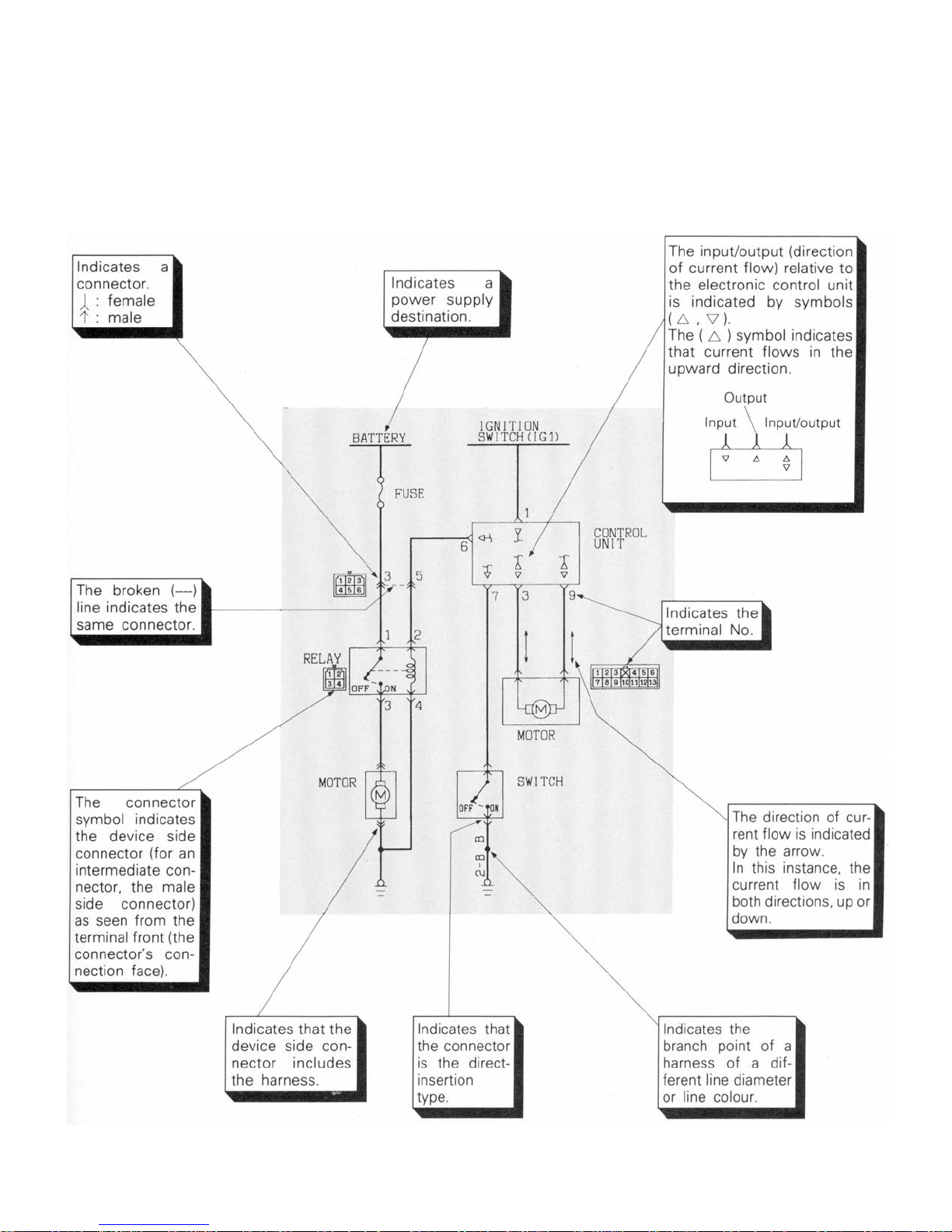
EXPLANATION OF CIRCUIT DIAGRAMS
The symbols used in circuit diagrams are used as
described below.
Manual
NOTE
For detailed information concerning the reading of circuit
diagrams, refer to the separate manual of
WIRING".
"ELECTRICAL

NOTES
This electronic document was created from material published and copyrighted in 1992 by Mitsubishi Motor
Corporation (MMC). All rights to the original material are reserved by them.
This electronic document may be distributed freely, without financial charge. Note that this document is not an exact
replica of the original manual. Because of this, copies of this document are easily identified.
MMC cannot be held liable for any changes that have occurred. Typographical and factual errors may have been
introduced, and some may have been corrected, while others may have been preserved. MMC and I disclaim all
liability for direct, indirect, incidental, or consequential damages or personal injury that may result from any use of the
information in this manual. MMC and I make no warranty, claim, or representation, expressed or implied, concerning
the accuracy of the material here, or the suitability of the information or instructions for any purpose.
Please note that this manual does not cover vehicles destined to the USA and Canada. The vehicles covered include the
turbocharged model destined for Europe, Australia, New Zealand, the Gulf Coast Council (GCC) nations, and General
Export (those territories other than Europe, Australia, New Zealand, GCC, USA, and Canada). In some cases,
information here may be identical to that for USA and Canada vehicles. In other case, the information does not apply
to USA and Canada vehicles.
I used an Epson Perfection 2450 scanner and Readiris Pro 9.04 to scan a single sheet (page) and recognize images,
text, and tables. I placed a sheet of black paper behind the sheet to be scanned to reduce bleed-through of images and
text from the back of the sheet or from other sheets. Scanner options in Readiris were set to grayscale, 400 dpi, letter
format, and contrast and brightness set to 299 to reduce the yellowing caused by the age of the manuscript. Readiris
allows the identification and selection or elimination of areas of the scanned image that are text, graphics, or table
format. This did not allow the embedding of graphics into text areas or vice versa. These two areas may overlap but
this created visual confusion. Pages were deskewed as necessary. The formatted, scanned page was saved in MS Word
document format.
I used MS Word 2002 to make spelling corrections, format the page size (8.5” x 11”), and set margins, generally 0.5”
all around. Re-arranging of objects occurred on some pages. From Word, I “printed” the page to Adobe Distiller 7.0.0,
creating a PDF file for each page. Distiller was set to not compress images. This increases the size of the final
document, but improves resolution and clarity of the images. In Adobe Acrobat 7.0.0, I concatenated the individual
PDF files into a single document, adding bookmarks and thumbnails.
I tested the final document with Acrobat and Acrobat Reader versions 5, 6, and 7. No problems were encountered with
versions 6 and 7. However, with Acrobat version 5 errors were encountered. These were avoided by having the
Bookmarks panel on the left “open”. I recommend using version 6 or 7 of Acrobat or Acrobat Reader to view this
document.
I thank the dedication and generosity of Jan Borgelin for getting an original printed version of this publication to me.
Jeff Lucius, February 2005

0-1
GENERAL
CONTENTS
DESIGN STRATEGIES FOR
DEVELOPMENT ...........................................................
Basic Themes for Development ................................2
COMMODITY FEATURES ............................................
TECHNICAL FEATURES .............................................
Exterior ......................................................................4
Interior ........................................................................5
Engine ........................................................................6
Transaxle ...................................................................9
Clutch Booster ........................................................ 10
2
3
4
Chassis ...................................................................11
Supplemental Restraint System (SRS) .................. 13
Small Amount Refrigerant System
(Air Conditioner) ...................................................... 14
Theft-alarm System ................................................ 15
Serviceability ........................................................... 16
VEHICLES IDENTIFICATION .................................... 17
Model ...................................................................... 17
Model Code ............................................................. 17
MAJOR SPECIFICATIONS ........................................18
0-2
A
GENERAL - Design Strategies for Development
DESIGN STRATEGIES FOR DEVELOPMENT
BASIC THEMES FOR DEVELOPMENT
New 4WD Sports Car
4WD system that accurately transmits the power of
the engine to the road surface, thus eliminating the
danger that normally accompanies speed, has been
adopted in a sports car so that anyone can comfortably
Exhilarating driving and safety
Faithful and speedy responsiveness to the intentions of
the driver and direct response. Also, safety equipment
has been adopted in order to maintain safety.
drive in a sporty manner.
The DOHC twin-turbochargers and twin-intercoolers
coupled with the 4WD maintain overwhelming
performance
In pursuit of sports car styling
Stylish design that abolishes design compromises.

•
•
•
•
GENERAL - Commodity Features 0-3
COMMODITY FEATURES
Dynamic real sports styling
Interior with an abundantly
sporty feel
Excellent driving performance
Excellent steering stability
Low and wide proportions
• Capsule image due to glass with complex curves
• Large-diameter wide tyres that symbolize super 4WD
Sports cockpit centered around the driver
• Simple interior qesign
• Front seat which stresses driving performance
• Excellent acceleration performance from a standing start due to
a high-performance engine and 4WD
• Extra-wide tread and wide tyres together provide a high limit for
cornering performance
• High-performance brakes due to the combination of 4-piston
aluminum caliper brakes and 4-wheel ABS
• Optimization of torque distribution to front and rear wheels
High-tech components
Safety features
Full-time 4WD and 5-speed
• Combination of 4WD, 41S, 4ABS and 4WS
• 4-piston aluminum caliper brakes
• Active aero system
• SRS air bag
4WD
• 4ABS
• SRS air bag
• Rear seat 3-point seat belts
• High-mounted stop lamp
• Side door beam
• Fire-resistant materials used inside the passenger compartment
MfT
manufactured by GETRAG
0-4 GENERAL - Technical Features
TECHNICAL FEATURES
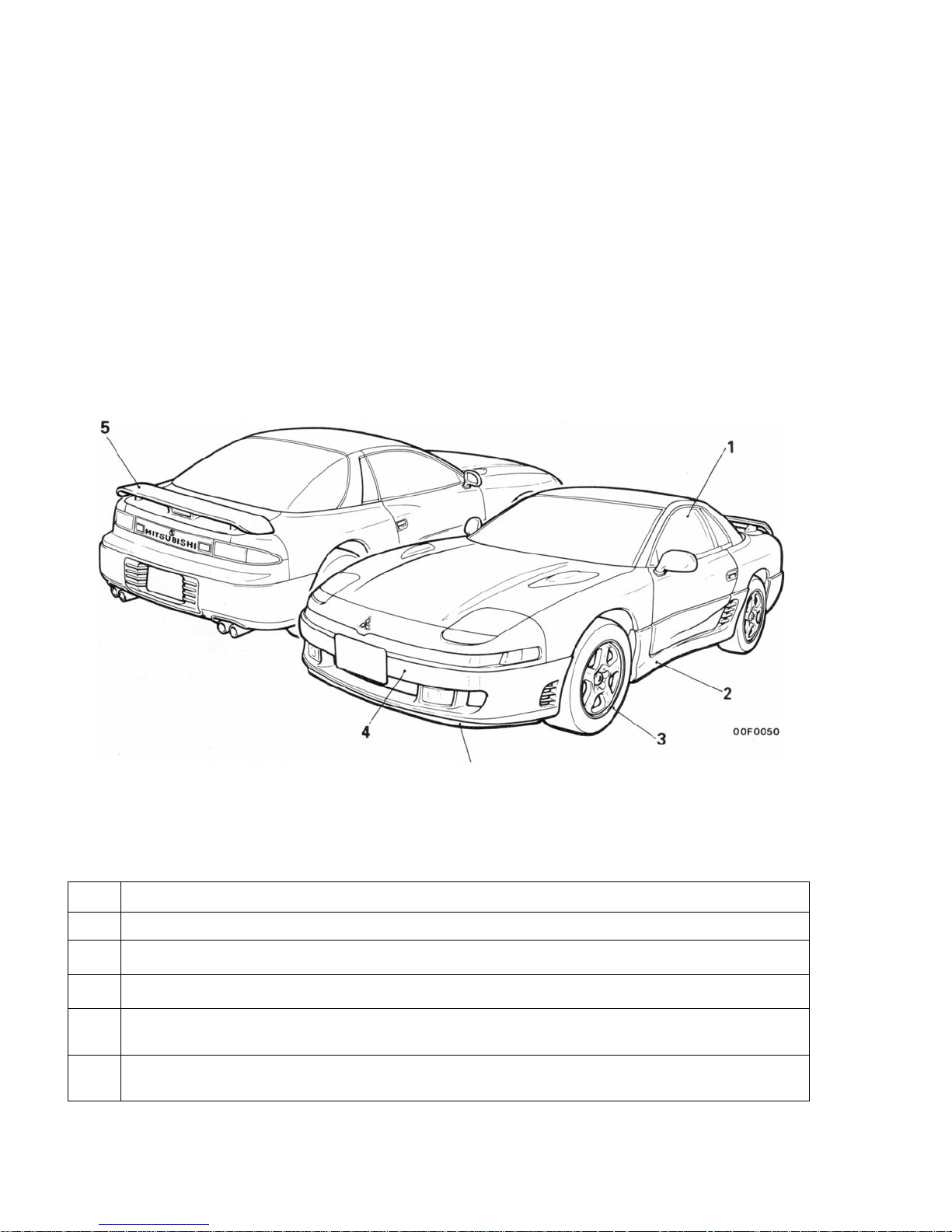
EXTERIOR
Dynamic sports car proportions with wide tread and
tight interior.
No. Features
1 The forward passenger compartment looks like a capsule, using glass with complex curves.
2
Side air dam that provides improved aerodynamic characteristics for the side of the vehicle.
3
17" aluminum wheel and wide tread tyre to create the image of a highyerformance sports car.
4 Large soft-face bumper (with built-in bumper absorber) that gives the feeling ot being one unit with the
body.
Active aero system improves aerodynamic characteristics when driving at high speed. (movable front
5
venturi skirt and rear spoiler)
5
GENERAL - Technical Features 0-5
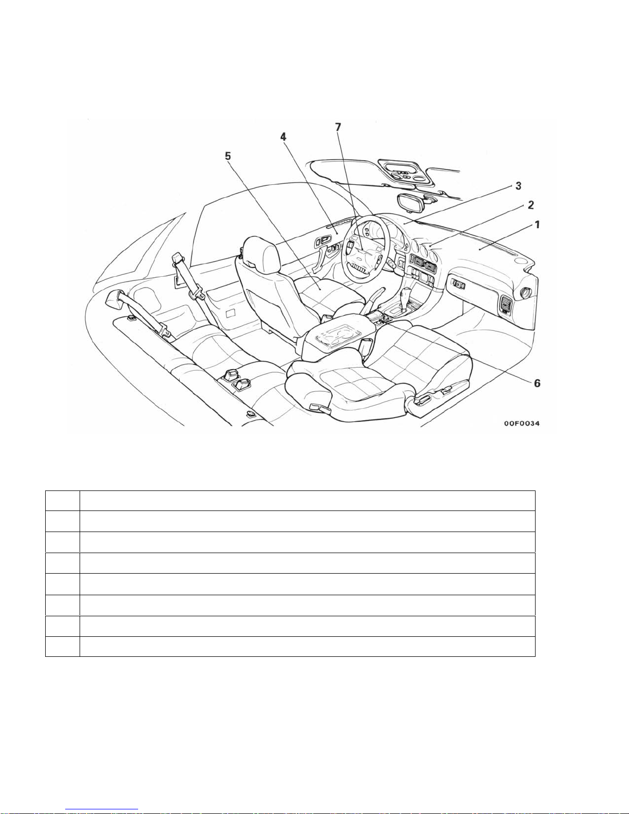
INTERIOR
Interior that creates a real feeling of a cockpit
centering around the driver.
No. Features
An instrument panel that emphasizes a feeling of closeness.
1
Round 3-meter arrangement with sporty imag.e.
2
3 Easy-to-see goggle type meter cluster.
4 Full round door trim that appears to be one with the instrument panel.
Superior sports type front seat that gives support.
5
6
High, wide and large floor console.
Sports steering wheel with built-in air bag (SRS).
7

0-6
GENERAL -
Technical Features
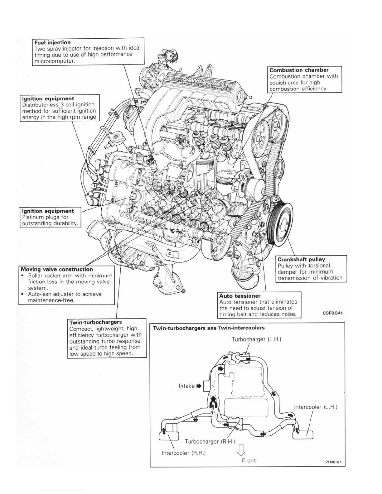
ENGINE
A 3.0L DOHC engine with twin-turbochargers and twin-intercoolers have been developed to provide even higher
output and higher performance.
SPECIFICATIONS
Items
Displacement
3
(cu. in.)
cm
Maximum output
kW (PS)/rpm
Maximum torque
kgm (Nm)/rpm
Specifications
2972 (181.4)
210 (285) / 6,000
41.5 (407) /3,000
FEATURES
High performance and low fuel consumption
• The roller rocker arm reduces the valve-actuation torque as well as fuel consumption.
• Improved response and fuel consumption have been achieved by electronic control multi-point fuel injection.
• Electronic control of fuel pump fuel discharge for high response and low fuel consumption.
• Overwhelming acceleration due to combination of the twin-turbochargers and twin-intercoolers.
• A lightweight sodium-filled vacuum valve has been developed for use as the exhaust valve to improve valve follow in high-
speed ranges. <Vehicles for Europe>

GENERAL - Technical Features
Quiet operation
• Noise and vibration have been decreased by the adoption of roller rocker arms.
• Noise generated by the valve mechanism has been decreased by the hydraulic auto lash adjusters.
• Both powerful exhaust sound fitting a high performance vehicle and quietness due to the active exhaust system.
• Reduction in noise and vibration by improving the rigidity of the cylinder block.
• Vibrations have been decreased by the adoption of bearing caps with beams which increase the rigidity of the crank-
shaft support points.
• Reduction in vibration due to the use of a crankshaft pulley with torsion damper and, because of that, improvement in
the durability of the belts.
Serviceability
• Complete self-diagnosis functions.
• Enhanced reliability through the adoption of gold-plated connector terminals.
• Use of an auto tensioner achieves maintenance-free, automatic adjustment of timing belt tension.
• Use of the auto-lash adjusters achieves maintenance-free, automatic adjustment of valve clearance.
• The 3-coil distributorless ignition system supplies sufficient ignition energy even during high speed operation.
0-7
0-8
GENERAL - Technical Features
GENERAL - Technical Features 0-9
TRANSAXLE
W5MG1 TYPE MANUAL TRANSAXLE
The W5MG1 type manual transaxle is a full-time 4WD
manual transaxle made by GETRAG
* and newly
developed to match the high output and high torque of
the 6G72-DOHC (Turbo) engine.
1. Sportier driving is possible by using a centre
differential method with viscous coupling for
distributing (front 45: rear 55) front and rear torque
unevenly.
2. A double-cone synchronizer for 1st and 2nd speeds
and a reverse synchronizer are used and, in
addition to sure shifting performance, the shift
feeling is also improved.
3. Low vibration and low noise are realized by the use
of high precision gears and high rigidity shaft.
*
GETRAG is a German manufacturer who develops
and manufactures high performance transaxles
especially in Europe.
0-10 GENERAL - Technical Features
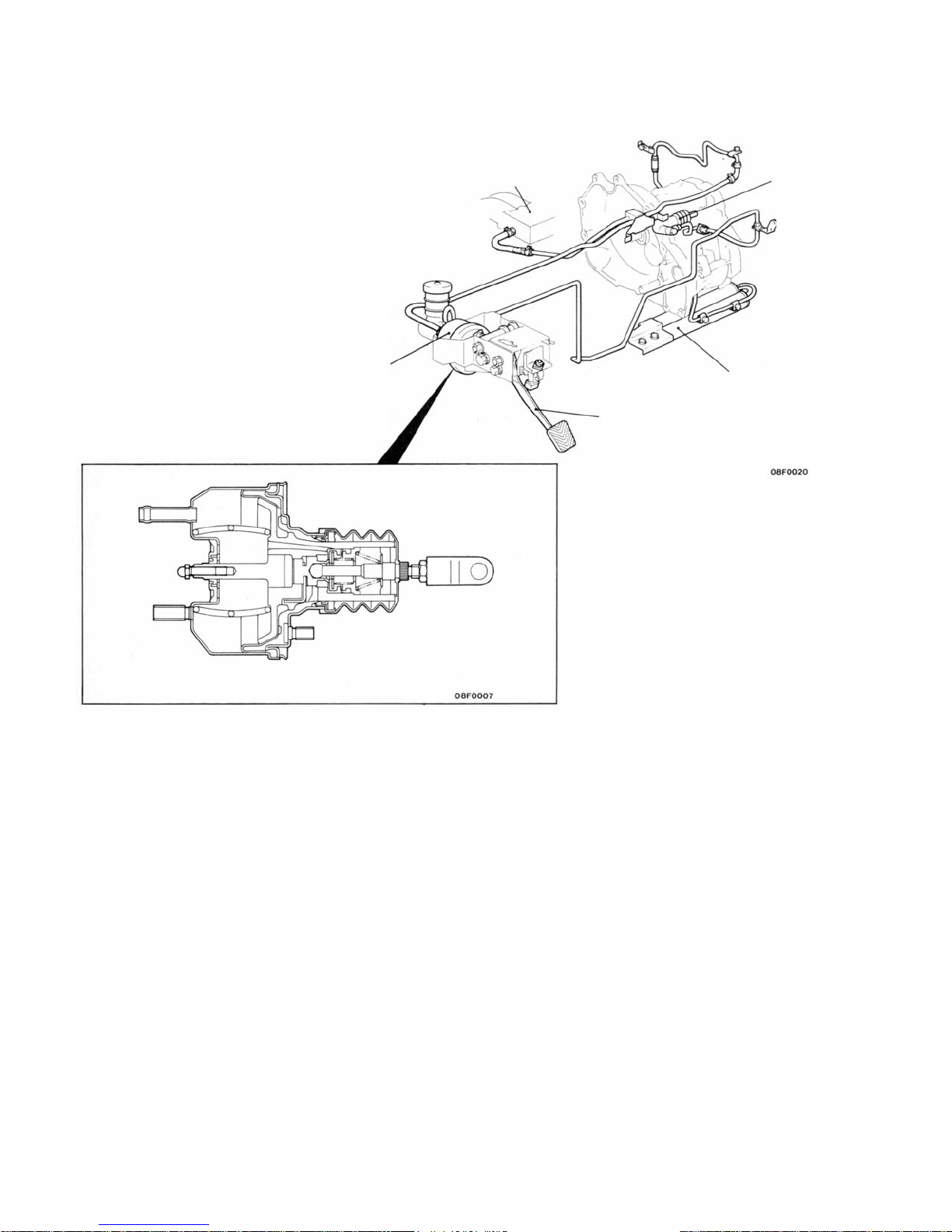
CLUTCH BOOSTER
A 4" single type clutch booster is used to reduce the
force needed to depress the clutch pedal.
Air intake plenum
Release cylinder
Clutch booster
Vacuum tank
Clutch pedal
GENERAL - Technical Features
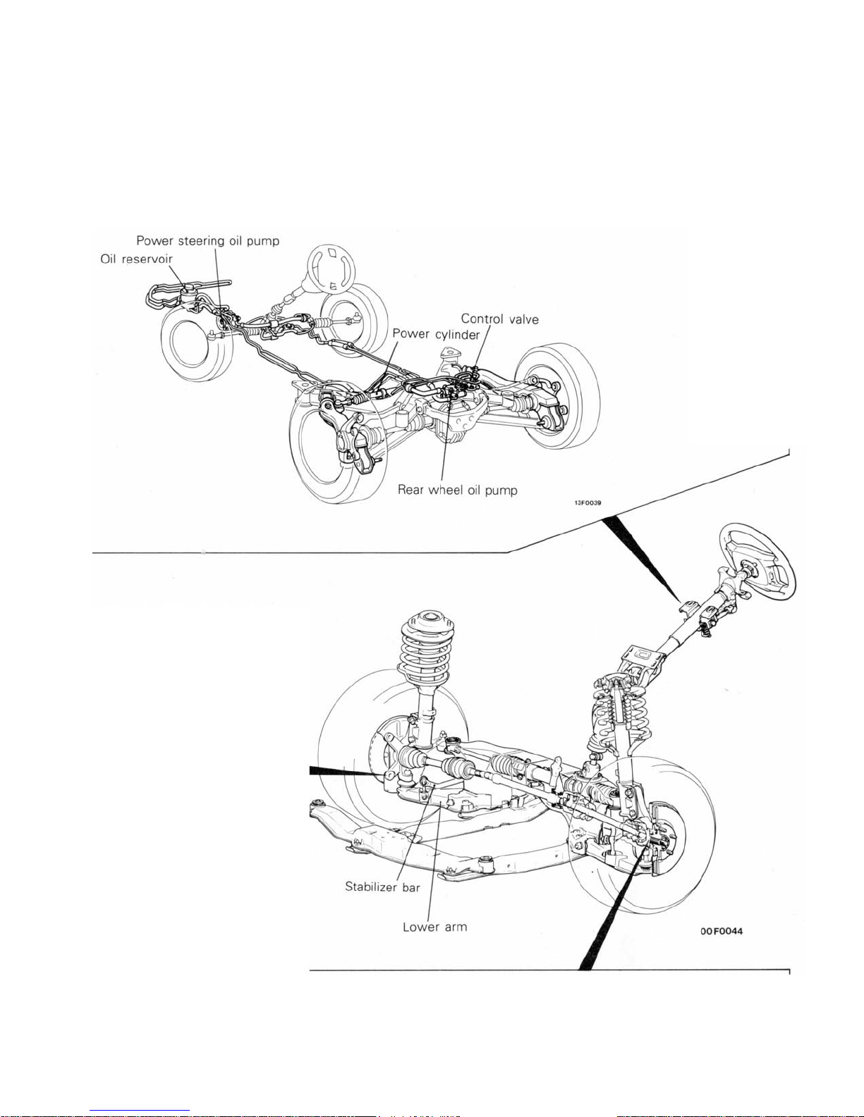
CHASSIS
Steering
• A compact lightweight integral type rack and pinion type power steering for outstanding steering response.
• Tilt steering construction for ideal steering position.
• SRS built into the steering wheel to protect the driver.
• 4-wheel steering system (4WS) for improved stability in the medium and high speed range.
0-11
Front Suspension
• Very lightweight and rigid McPherson
strut type independent suspension.
• Offset coil spring for comfortable ride.
• Anti-diving geometry for outstanding
stability.
• Negative offset geometry for superior
stability when braking.
• Electronic control suspension (ECS) for
both driving stability and riding comfort.
• Liquid filled bushing to reduce noise.
Front Axle
• BJ-TJ type constant velocity joint with high transmission efficiency and minimum vibration and noise.
• Isometric drive shaft for reduced vibration, noise and torque steer.
• A unit ball bearing consisting of the hub and bearing for good serviceability and little rolling
resistance.
0-12 GENERAL - Technical Features
g
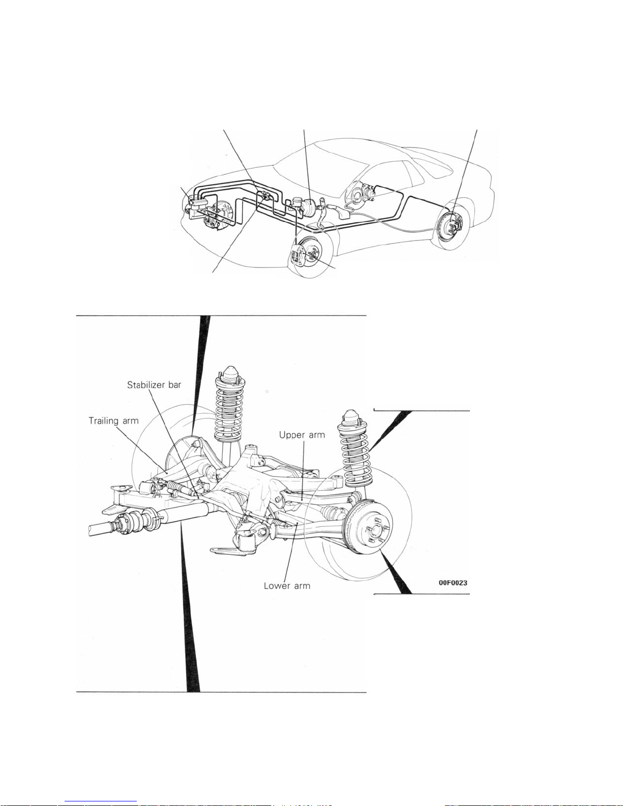
Brake
X-arrangement of lines that
maintains balanced braking in
front and rear even if the
hydraulic system is lost.
4-wheel anti-lock braking
system (4ABS) using 4sensor, 2-channel lock
method.
Dual proportioning valve
for control of rear wheel brakin
8+9 inch tandem brake
booster to reduce the
force needed to depress
the brake pedal.
.
Rear drum-in-ventilated disc
brake with built-in parking
brake and featuring good
braking stability.
Face-to-face and different diameter 4piston front ventilated disc brake with
stable braking force and good braking
feeling.
Rear Suspension
• Double wishbone type independent suspension for
outstanding riding comfort.
• Electronic control suspension (ECS) for both stable
handling and riding comfort.
Propeller Shaft
• 3-section 4-joint type propeller shaft with two center bearings.
• Robro joint to absorb lengthwise and angular change and prevent transmission of vibrations.
• Anti-vibration type propeller shaft (rear propeller shaft) to reduce vibration and noise from the drive train.
Rear Axle
• BJ-TJ type constant velocity joint with high transmission
efficiency and minimum vibration and noise.
• Viscous coupling type limited-slip differential.
GENERAL - Technical Features
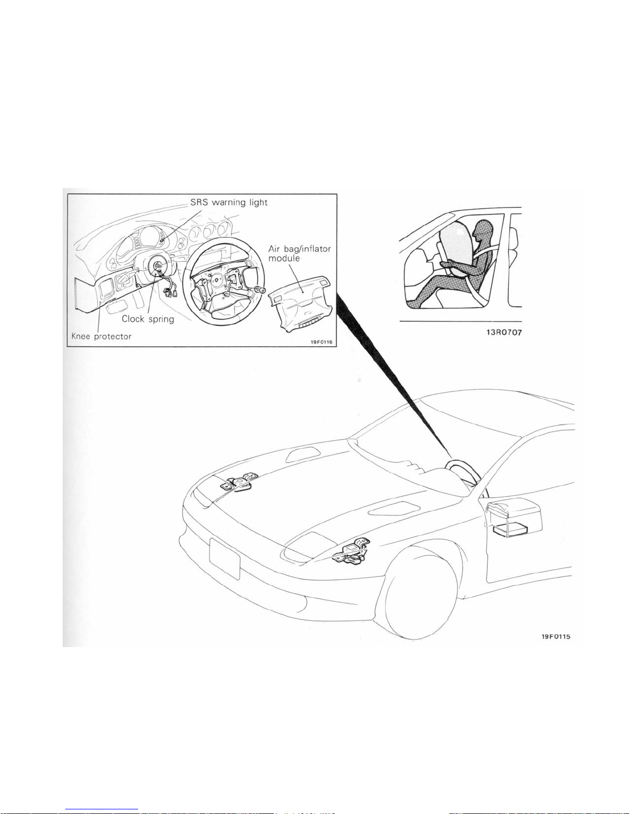
SUPPLEMENTAL RESTRAINT SYSTEM (SRS)
SRS is a system that works with the seat belt and is
designed as auxiliary equipment to the seat belt.
It only functions to protect the upper body of the driver
0-13
when a shock that is over the design value (deceleration
G) is added to the entire vehicle from the front.
0-14
GENERAL - Technical Features
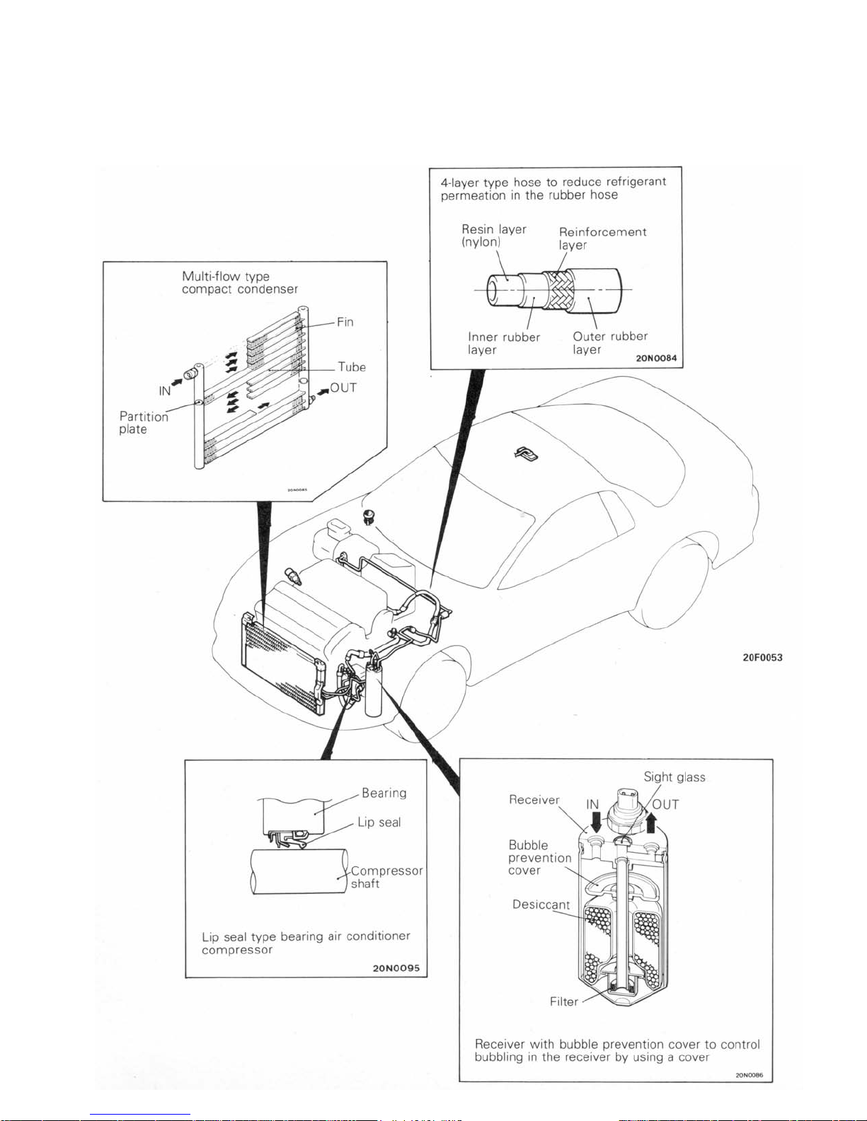
SMALL AMOUNT REFRIGERANT SYSTEM (AIR CONDITIONER)
In order to protect the ozone layer, the small amount
refrigerant system was developed by improving the
structural parts of the air conditioner, making it more
compact, etc. in order to reduce as much as possible
the amount of chloro-fluoro carbon used as the
refrigerant in automobile air conditioners.
A
GENERAL - Technical Features
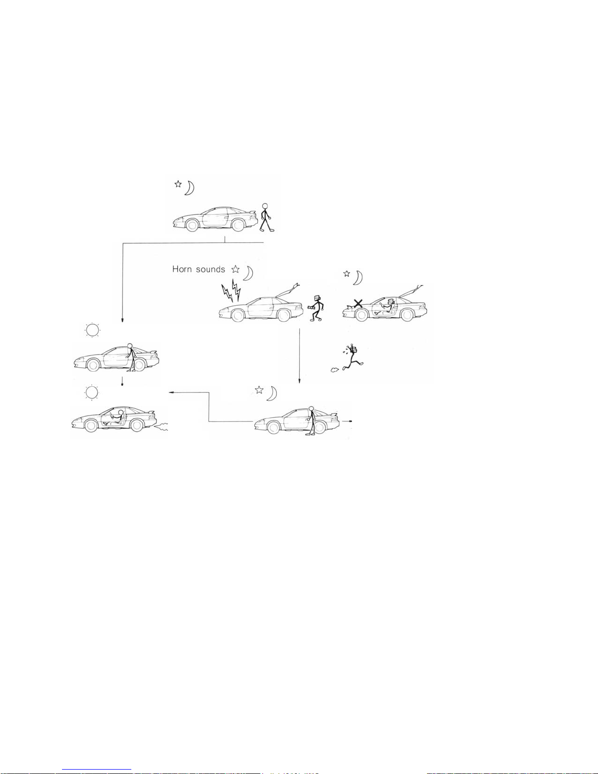
THEFT-ALARM SYSTEM
To make the vehicle theftproof, this system is designed to operate the horn intermittently for 30 seconds when the locked door, hood or tailgate has
been forced open without using a key. Furthermore,
the starter circuit is interrupted so that the engine
may not be operated.
About 20 seconds after all doors are closed and
locked, the tailgate is closed, and the hood is
closed
Æ
SYSTEM ARMED
0-15
Authorized
Driver opens door with the key
SYSTEM DISARMED
Normal starting
Unauthorized
A door, tailgate or hood is broken to
open
Æ
ALARM ACTIVATED
Driver unlocks a door or tailgate with the key.
Engine is disabled and will not start
LARM DEACTIVATED
(SYSTEM DISARMED)
16F0295

0-16
GENERAL - Technical Features
SERVICEABILITY
A series of investigations from a variety of angles are
carried out starting from the planning and design stages,
to produce a vehicle with complete diagnosis functions
Items of improved serviceability
• Adoption of hydraulic-type lash adjusters which make valve clearance adjustment unnecessary
• Adoption of an auto tensioner which makes timing belt tension adjustment unnecessary
• Adoption of a distributorless 3 coil ignition system
• Adoption of a camber adjustment mechanism in the front suspension
• Adoption of an alignment adjustment mechanism in the rear suspension
• Adoption of an outer disc method which makes brake disc removal and installation simple
• Adoption of audible pad wear indicators in the brakes
• Adoption of a drum in parking disc type brake to improve workability for the rear brakes
• Adjustment of gap between wheel speed sensors and rotors in 4ABS
• Colour-coding of service connectors (for ignition timing adjustment, fuel pump inspection and engine speed
inspection) to distinguish then from other connectors and make them easier to find
• Expansion and full realization of the self-diagnosis system
• Improvement in reliability due to harness junction connectors
• Centralization of relays
• Receiver piping connection has been made into a flange fitting and the end of the piping section has been flared to
prevent falling off of O-rings
and a reduced need for maintenance, with
improvements in reliability and durability.

GENERAL -
V
V
V
V
ehicle Identification
0-17
VEHICLE IDENTIFICATION
MODEL
VEHICLES FOR EUROPE
Model code Engine model Transmission model Fuel supply system
Z16AMNGFL6
Z16AMNGFR6
EHICLES FOR GENERAL EXPORT
Model code Engine model Transmission model Fuel supply system
Z16AMNGFL
Z16AMNGFR
EHICLES FOR GCC
6G72 [2,972 cm3 (181.4 cu. in.)] W5MG1 MPI
6G72 [2,972 cm3 (181.4 cu. in.)] W5MG1 MPI
Model code Engine model Transmission model Fuel supply system
Z16AMNGFLW 6G72 [2,972 cm3 (181.4 cu. in.)] W5MG1 MPI
EHICLES FOR AUSTRALIA
Model code Engine model Transmission model Fuel supply system
Z16AMNGFR8 6G72 [2,972 cm3 (181.4 cu. in.)] W5MG1 MPI
MODEL CODE
Z1 6 A M N G F L 6
1
1. Development order
Z1 - MITSUBISHI 3000GT
(Full time 4WD)
2. Engine type
6 - 2,972 cc (181.4 cu. in.), petrol
3. Sort
A - Passenger car
4. Body style
M - 2-door hatchback
5. Transmission type
N - 5-speed manual transmission
6. Trim code
(&
Drive train)
2 3
4
5
6
7
8
9
7. Specified engine feature
F - Turbocharger (with intercooler)
8. Steering wheel location
L - Left hand
R - Right hand
9. Destination
6 - For Europe
8 - For Australia
W - For GCC
None - For General Export
0-18
OO
GENERAL - Major Specifications
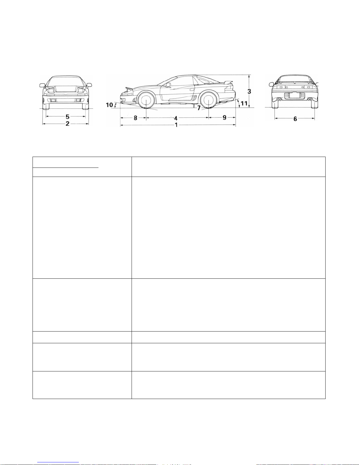
MAJOR SPECIFICATIONS
Items Z16AMNGFL6 Z16AMNGFL Z16AMNGFLW
Dimensions mm(in.)
Overall length 1 4,560 (179.5)
Overall width 2 1,840 (72.4)
Overall height (unladen) 3 1,285 (50.6)
Wheelbase 4 2,470 (97.2)
Track-Front 5 1,560 (61.4)
Track-Rear 6 1,580 (62.2)
Ground clearance (unladen) 7 145 (5.7)
Overhang-Front 8 1,030 (40.6)
Overhang-Rear 9 1,060 (41.7)
Angle of approach degrees 10 11.2°
Angle of departure degrees 11 17.3°
, Z16AMNGFR6 Z16AMNGFR Z16AMNGFR8
F0015
Weight kg (Ibs.)
Kerb weight 1,740 (3,836)
Gross vehicle weight 2,120 (4,674)
Max. axle weight
Front 1,150 (2,535)
Rear 1,020 (2,249)
Seating capacity 4
Engine
Model 6G72
Total displacement cm3 (cu.in) 2,972 (181.4)
Transmission
Model W5MG1
Type 5-speed manual
/

1-1
CONTENTS
ENGINE
-
GENERAL INFORMATION .........................................2
Specifications ......... ............................................... 2
Engine Sectional View ............................................ 2
BASE ENGINE ..............................................................
Oil Jet .........................................................................4
Main Bearing Cap ......................................................4
Crank Angle Sensor and
Cam Position Sensor .................................................5
Crank shaft ................................................................5
Exhaust Valve ...........................................................5
MOUNTING ..................................................................
LUBRICATION SYSTEM ............................................. 7
COOLING SYSTEM .....................................................
Specifications ............................................................8
INTAKE/EXHAUST SYSTEM .................................... 10
Twin-turbochargers and Twin-intercoolers ………. 10
Turbo Pressure Control ...........................................10
Exhaust Pipe .......................................................... 11
FUEL SYSTEM ...........................................................12
Fuel-pressure Control Valve .................................. 12
Fuel Tank ............................................................... 12
4
6
8
CONTROL SYSTEM …………………………………....14
System Block Diagram ……………………………….15
Sensors ……………………………………………….. 16
Actuators ……………………………………………….18
Fuel Injection Control …………………………………19
Idle Speed Control (ISC) …………………………… 20
Mechanical Dashpot ………………………...............21
Ignition Timing and
On Time Control ......................................................22
Power Supply and
Fuel Pump Control ..................................................23
Fuel Pump Discharge
Volume Control ………............................................ 24
Turbo Meter Control ... ............................................ 24
Turbo Pressure /Control .......................................... 25
Fuel Pressure Control ............................................. 26
Air Flow Sensor (AFS)
Filter Reset Control ................................................. 26
Self Diagnosis System ............................................ 27
EMISSION CONTROL SYSTEM ................................30
CRUISE CONTROL SYSTEM ....................................32

1-2
ENGINE -
General Information
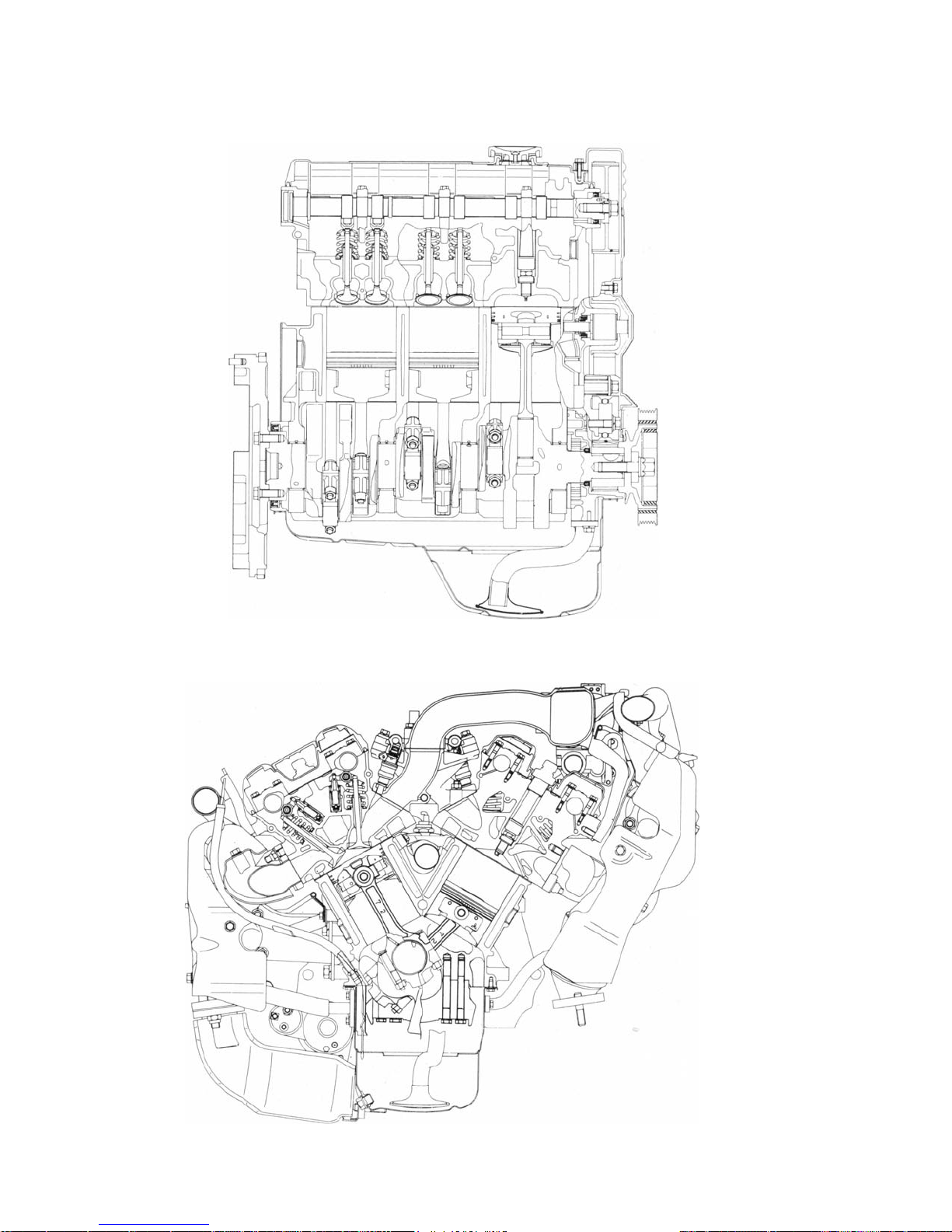
GENERAL INFORMATION
The engine is a V-type 6-cylinder (bank angle 60°) 2,972
3
(181.4 cu.in.) DOHC 24 valve design and is
cm
basically the same as the engine equipped in the
SIGMA. However, twin turbochargers and twin intercoolers have been installed to provide even higher
output and higher performance.
SPECIFICATIONS
Items Specifications
Total displacement cm3 (cu. in.) 2,972 (181.4)
Arrangement and number of cylinders V type, 6 cylinders
Combustion chamber type Pentroof type
Number of intake and exhaust valve (per cylinder) 2 each
Valve mechanism OHV, DOHC (per bank)
NOTE
For details of the basic engine structure, refer to the
previously-issued '91 SIGMA Technical Information
Manual. (Pub. No. PYGE9008).
Bore x stroke mm (in.) 91.1 x 76.0 (3.59 x 2.99)
Compression ratio 8.0
Maximum output PS/rpm 285/6,000
Maximum torque kgm/rpm 41.5/3000
Valve timing Intake Opened 16° BTDC
Exhaust Opened 50° BBDC
Fuel supply system Electronic controlled multi-point fuel injection
Ignition system Power distribution method Electronic controlled 3-coil type
Ignition timing control method Electronic controlled type
Closed 55° ABDC
Closed 17° ATDC
ENGINE -
1-3
General Information
ENGINE SECTIONAL VIEW
7EN0477
7EN0478
1-4
BASE ENGINE
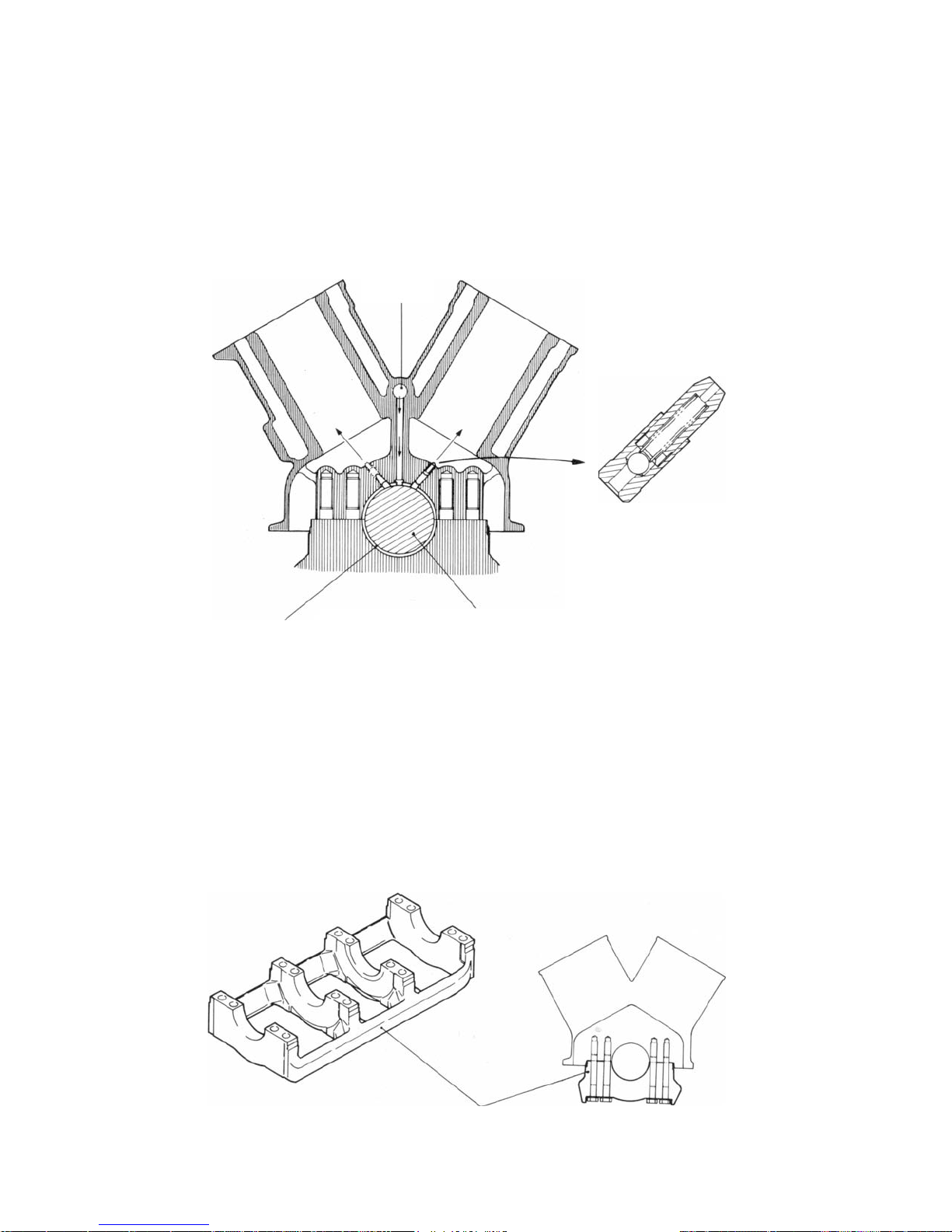
OIL JET
There is an oil jet for cooling the pistons.
ENGINE - Base Engine
Main gallery
Main bearing
Crankshaft
MAIN BEARING CAP
The main bearing caps are of a conventional integrated
type with beam. By tightening each of the bearing
sections with 4 bolts, rigidity has been improved and
Oil jet
[opens valve at
2
2 kg/cm
(28 psi) or more]
7EN0479
vibration from the main drive section has been
reduced.
Main bearing cap
7EN0480
ENGINE - Base Engine 1-5
N
A
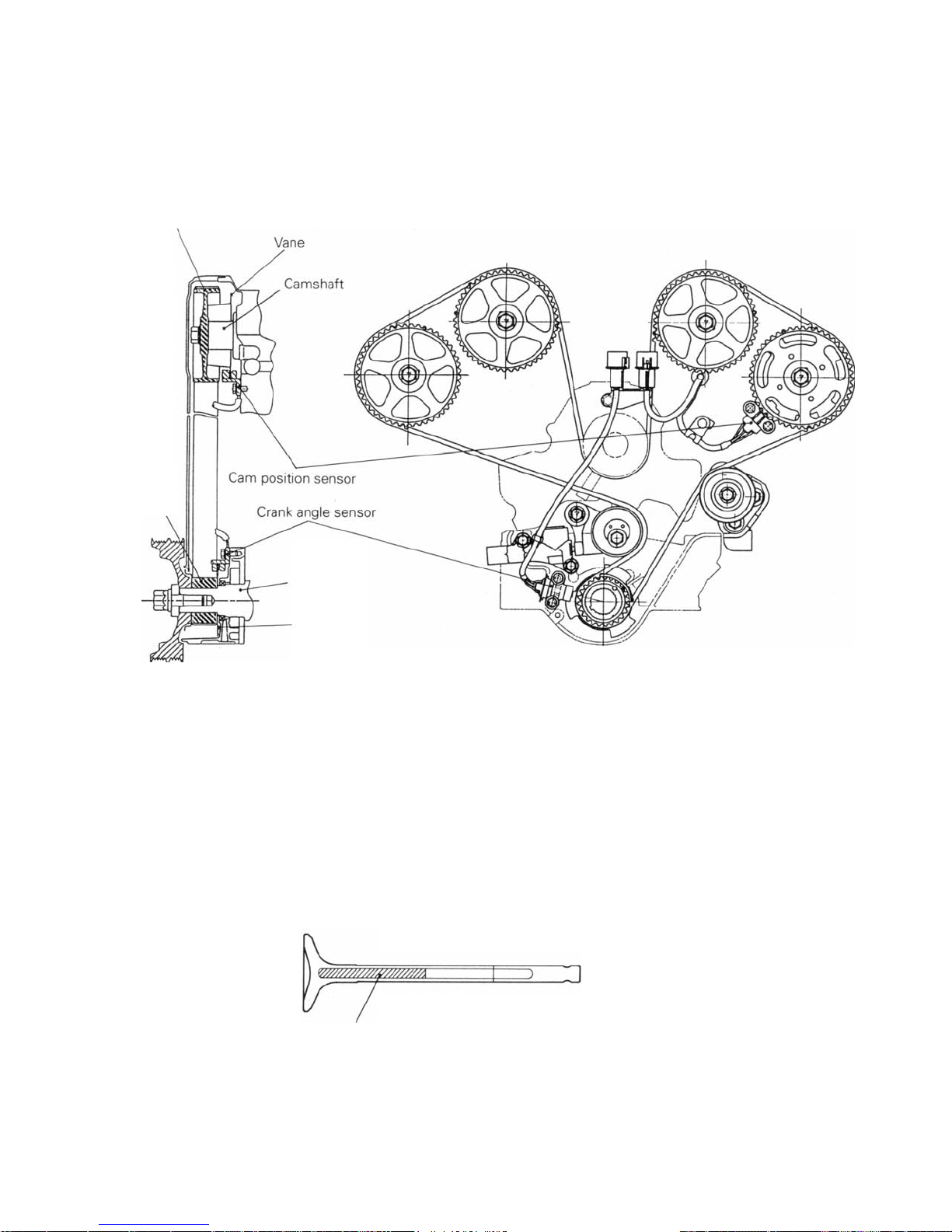
CRANK ANGLE SENSOR AND CAM POSITION SENSOR
An ultra-small crank angle sensor and cam position a large space saving and to provide improved
sensor have been positioned inside the crankshaft crank angle detection precision.
sprocket and camshaft sprocket respectively to realize
Cam sprocket
Crank sprocket
Crankshaft
Vane
7EN0481
CRANKSHAFT
steel crankshaft has been adopted in order to cope
with the increased engine output and to provide
reduced noise and reduced vibration.
EXHAUST VALVE (VEHICLES FOR EUROPE ONLY)
Lightweight sodium-filled vacuum valves have been been improved, and improvements have been real-
developed for use as the exhaust valve to improve ized in anti-knock characteristics and fuel consump-
valve follow in high-speed ranges. At the same time, tion efficiency at high speeds.
the cooling performance of the exhaust valve has
Caution on handling the metallic sodium-filled exhaust valve.
Because metallic sodium reacts violently when it For specific details, refer to the Engine Workshop
comes into contact with water or moisture to gener- Manual.)
ate hydrogen gas, there is a danger that explosion or
fire may occur, so it should be treated with caution.
a
7EN0482
01R0639
01F001
01N0101
1-6
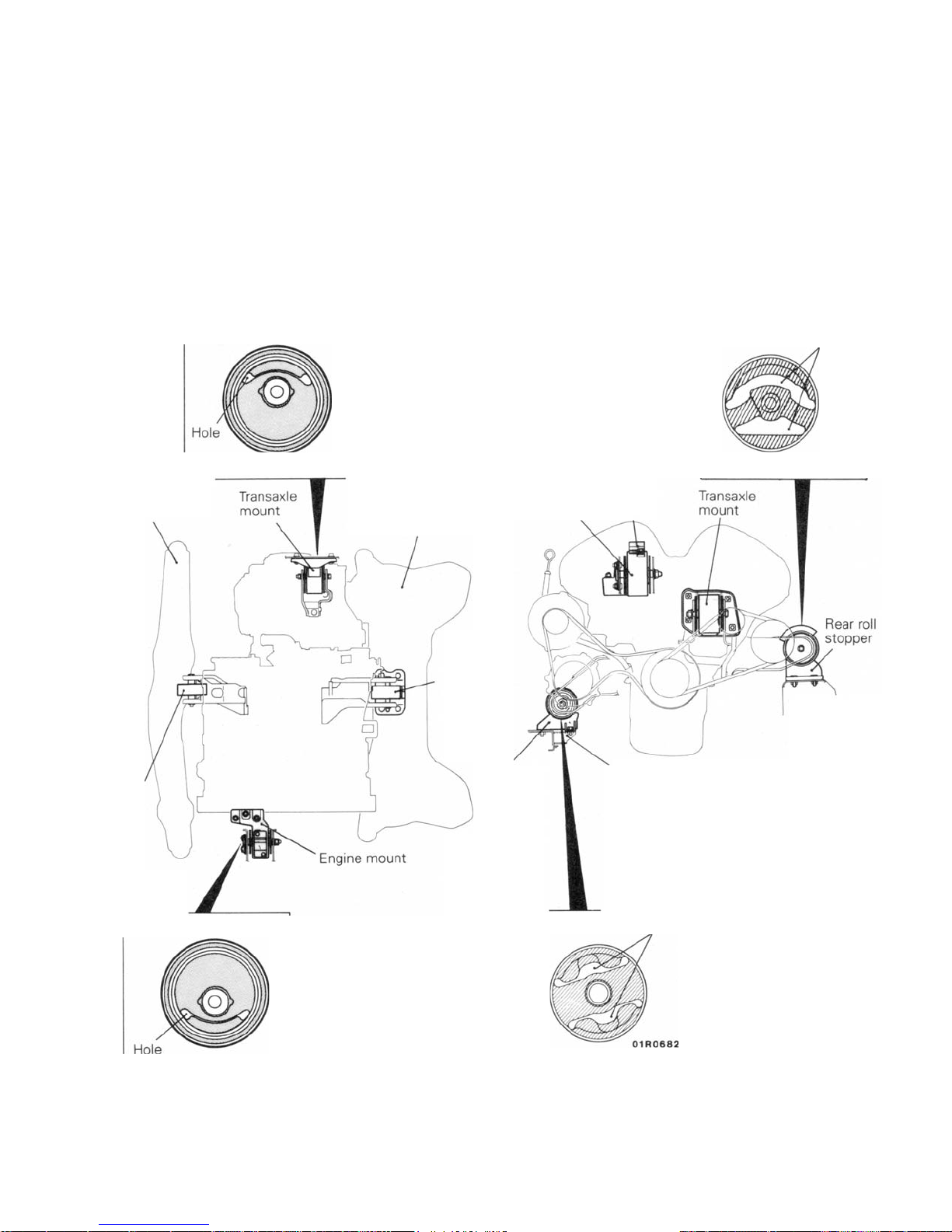
MOUNTING
ENGINE -
Mounting
The engine mounts use a principal axis inertia support
system.
This support method on the principal axis inertia is a
structure that supports the top of the engine and top of
the transmission to effectively control engine vibration.
A dynamic damper is provided on top of the engine
mount to cut out high-frequency noise.
Insulator
01N0101
No. 1 crossmember
No.2 crossmember
Roll stoppers (front and rear) are installed on the
crossmember that is elastically supported on the body to
reduce transmission of engine vibration to the body.
The various mounts have the following features
• Each insulator has a hole to effectively absorb small
and large vibrations.
Engine
mount
Dynamic
damper
Insulator
Hole
Front
~
Front roll
stopper
Insulator
Front
~
Rear
roll
stopper
Front roll
stopper
7
Insulator
No.1
crossmember
Hole
No. 2
crossmember
01 F0014

A
LUBRICATION SYSTEM
ENGINE - Lubrication System
1-7
n oil pressure gauge unit has been installed in all
models. In addition, an oil level sensor has been
Rocker arm
Lash
adjuster
Orifice
equipped in the oil pan (Vehicles for Europe).
Oil filter
Oil pressure
gauge unit
Oil cooler
To oil level relay •
Oil pressure
switch,
Relief
valve
Lash
adjuster
To
turbocharger
t,
I
Oil pan
Oil level sensor
7EN0483

1-8
•
COOLING SYSTEM
ENGINE - Cooling System
The cooling system uses a water cooling pressure
control circulation system and it has the following
features.
• The cooling (radiator) fan uses a motor driven system. The fan is driven by the motor only when
needed to efficiently control the cooling water
temperature and reduce engine output loss .
• The cooling fan is a full shroud type for improved
cooling performance.
The two step control system is used for the motor
driven cooling fan and condenser fan for less fan
noise, reduced vehicle vibration and improved
cooling when the engine is idling. (Refer to GROUP
7 - Condenser Fan and Radiator Fan Control for fan
speed operation mode.)
SPECIFICATIONS
Items Specifications
Cooling fan
Type Motor driven system
Water pump
Type Centrifugal type impeller
Drive method Timing belt
Thermostat
Type Wax type
Open valve temperature °C (ºF) 76.5 (170)
Radiator
Coolant capacity (including that in
condenser tank) dm3 (U.S. qts., Imp. qts.) 8.0 (8.5, 7.0)
Condenser tank capacity dm3 (U.S. qts., Imp. qts.)
Full 0.65 (0.69, 0.57)
Low 0.25 (0.25, 0.22)
Type Corrugated type

0
ENGINE - Cooling System
Items Specifications
Radiator fan motor
Maker Nippon Denso
Type Direct flow ferrite type
Rated load torque Nm (kgm, ft.lbs.) 53 (5.3, 39)
Speed rpm 2,080 ± 250
Current
Thermo sensor for radiator fan
Operating temperature °C (ºF)
OFF --+ ON 81-89 (178-192)
ON --+ OFF 77 (171) or more
Thermo sensor for condenser fan
Operating temperature
OFF --+ ON 91-99 (196-210)
ON --+ OFF 87 (189) or more
-
°C (ºF)
·A
13.6 ± 1
1-9
4 FOOO3

1-10
ENGINE -
Intake/Exhaust System
INTAKE/EXHAUST SYSTEM
TWIN TURBOCHARGERS AND TWIN INTERCOOLERS
Compact, lightweight, turbochargers with outstanding
response are used in each bank, front and rear, for the
best turbo feeling at all speeds, from low to high. The
turbocharger is a water-cooled TD04 type with waste
gate valve. The intercoolers are very efficient and each
Intake
one is arranged on the front and rear banks just like the
turbocharger. With the combined action of the
turbocharger and intercooler, powerful acceleration is
possible from any speed.
Turbocharger
Intercooler
Turbocharger
Intercooler
TURBO PRESSURE CONTROL
The waste gate operating pressure is controlled to
make possible flat turbo pressure characteristics
Intercooler
Air from
air cleaner
71N0107
over the entire rpm range and to provide a linear ac:celeration feeling.
¢
Air into engine
Exhaust
from engine
Waste gate
solenoid valve
Exhaust to
exhaust pipe
Waste gate actuator
71N0108

f
ENGINE -
Intake/Exhaust System
EXHAUST PIPE
The exhaust pipe is divided into three sections, front
pipe, centre pipe and main muffler. It is installed on the
body via a rubber hanger to reduce transmission o
vibrations from the exhaust system to the body. A dual
Oxygen sensor <Vehicles for Australia>
Heat protector <Vehicles
for Australia>
Flexible pipe
pipe is used for the front pipe to improve exhaust
efficiency, and a dual tail pipe with muffler cutter is used
as the main muffler.
1-11
Catalytic converter
(Right) <Vehicles for
Europe> or exhaust
pipe (Right) <Vehicles
for General Export, GCC and Australia>
05F0061
Pre-muffler
Catalytic converter
<Vehicles for Europe and Australia>
or pre-muffler <Vehicles
for General Export and GCC>

1-12
j
r
ENGINE - Fuel System
FUEL SYSTEM
The fuel system consists of electromagnetic fuel in-
ectors, delivery valves, a fuel pressure regulator for
regulating fuel pressure, and an electromagnetic fuel
pump which operates at high pressure. It is basically
the same as the fuel system in the conventional 6G7
engine, but the fuel pressure is controlled to 3.0 kg/
2
cm
. In addition, in order to verify the idling stability
immediately after re-starting the engine at high
temperatures, a fuel pressure control solenoid valve
which is the same as the one fitted in the convention-
al 4G63 engine.
The fuel tank is located under the luggage compartment floor and the fuel filters are in the fuel tank and
in the engine compartment to filter the fuel. For bette
serviceability, there is a terminal for the fuel pump
drive in the engine compartment and a service hole in
the luggage compartment; the pump and gauge
assembly can be removed without removing the fuel
tank.
Fuel pump drive
terminal
Fuel filter
Fuel pressure
regulator
PCV
Canister
~
Fuel injector
Delivery pipe
FUEL-PRESSURE CONTROL VALVE
Two-way valve
Protector
Fuel pump and
gauge assembly
Fuel tank
In-tank filter
03 FOO09

1-13
A
ENGINE - Fuel System
Normally, the negative pressure in the intake manifold
acts upon the fuel pressure regulator to maintain the
fuel pressure at a constant level with regard to the
pressure inside the intake manifold, causing the amount
of fuel injected to be controlled in proportion to the
injector drive time. However, if the engine is started
while the engine coolant temperature and the intake air
temperature are high, the engine control unit makes
FUEL TANK
The electric fuel pump, in-tank filter and fuel gauge unit
are built into the fuel tank.
The fuel tank has the following features.
• Baffle plates are placed inside the fuel tank to
prevent abnormal noise due to fuel movement.
• There is a reseve cup inside the fuel tank for
Thermistor
(for fuel warning light)
current flow to the fuel pressure control valve to activate
the fuel pressure regulator by means of atmospheric
pressure.
Because of this, the generation of fuel vapour due to
the high fuel pressure and high temperature is
avoided, and the idling stability immediately after restarting the engine at high temperatures is maintained.
smooth supply of fuel even when there is little fuel
remaining.
pump and gauge assembly that combines the
•
gauge unit and fuel pump in one unit is adopted.
• A drain plug is standard-equipped on all models.
Pump and gauge assembly
In-tank filter
Drain plug
Fuel tank
03F0008

1-14
CONTROL SYSTEM
ENGINE - Control System
The control system used is basically the same as that in
the conventional 6G72 engine in the SIGMA. However,
Main items changed or added Notes
Control relay and fuel pump power circuit have
been changed.
Crank angle sensor mounting position has been
changed. (Crank angle previously detected from Improvement in ignition timing control precision
the camshaft is now detected directly from the
crankshaft.)
Adoption of fuel pump relay No.2 and fuel pump Improvement in fuel pump reliability
resistor
Fuel pressure control has been added.
(Refer to P.1-26.)
Turbo pressure control has been added. Control additions to correspond to adoption of a turbocharger
Turbo meter control has been added.
Adoption of a twin oxygen sensor system Reduction in exhaust gas levels
<Vehicles for Europe, Hong Kong and Singapore>
·
·
·
some parts differ as shown below.
Simplified power circuit
Basically the same as the 4G9-DOHC engine
Improvement in crank angle sensor precision

SYSTEM BLOCK DIAGRAM
ENGINE - Control System
1-15
Remarks
The changed or added items with respect to the conventional engine are shown in bold letters.

1-16
SENSORS
Carn position sensor and crank angle sensor
ENGINE - Control System
6AF0009
Carn position sensor
The cam position sensor consists of a flux screening
plate fixed to the crankshaft sprocket on the rear bank
exhaust side and a sensor unit fixed to the cylinder
head. The crank angle sensor consists of a flux
screening plate fixed to the crankshaft sprocket and a
sensor unit fixed to the engine oil pump case. The cam
position sensor and crank angle sensor convert the
rotation of the camshaft and crankshaft into pulse sig-
NO.1 cylinder TOC signal
No. 2 cylinder No.3 cylinder No. 4 cylinder No.5 cylinder No.6 cylinder
TOC signal TOC signal TOC signal TOC signal TOC signal
J
Cam position
sensor signal
Crank angle
sensor signal
.. 5V
No. 1 cylinder
TOC signal
OV
5V
OV
6AF0002
Crank angle sensor
nals as shown in the illustration below, and input these
pulse signals to the engine control unit. Furthermore,
these waveforms are the same as those for the
conventional 6G7-DOHC engine, but the mounting
precision of the crank angle sensor has been improved,
making basic ignition timing adjustment unnecessary.
Two rev. of engine
7FU0729

1-1
ENGINE - Control System
7
Flux screening plate for Carn
position sensor
Flux screening plate for
crank angle sensor
Vane
6AF0010
Vane
6AF0003
The shapes of the flux screening plates used in the cam position
sensor and crank angle sensor are as shown in the illustration at left.
Detection of the cam position and crank angle is the same as for the
conventional 4G93-S0HC engine, where the magnetic flux passing
through the Hall element inside the sensor unit is alternately
screened and allowed through by the vanes on the flux screening
plate.
TWIN OXYGEN SENSOR <Europe, Hong Kong and
Singapore>
There are sub catalysts in both the front and rear banks in the engine.
In order to maintain the proper air/fuel ratio in both banks, there is an
oxygen sensor for each one before the catalyst of both banks to
enable feedback control of the air/fuel ratio for each bank separately.
Each oxygen sensor is the same as the conventional oxygen sensor
with heater.

1-18 ENGINE - Control System
ACTUATORS
FUEL PUMP RELAY NO.2
Fuel pump relay No.2 is the relay that changes the supply voltage to
the fuel pump in 2 steps, High/Low.
The engine control unit controls the amount of fuel discharged from
the fuel pump by changing the supply voltage.
FUEL PUMP RESISTOR
The fuel pump resistor lowers the supply voltage to the fuel pump.

ENGINE -
Control System
FUEL INJECTION CONTROL
The fuel injection control method is basically the same
as that used in the conventional 6G72 engine.
SYSTEM CONFIGURATION DIAGRAM
1-19
1-20
ENGINE -
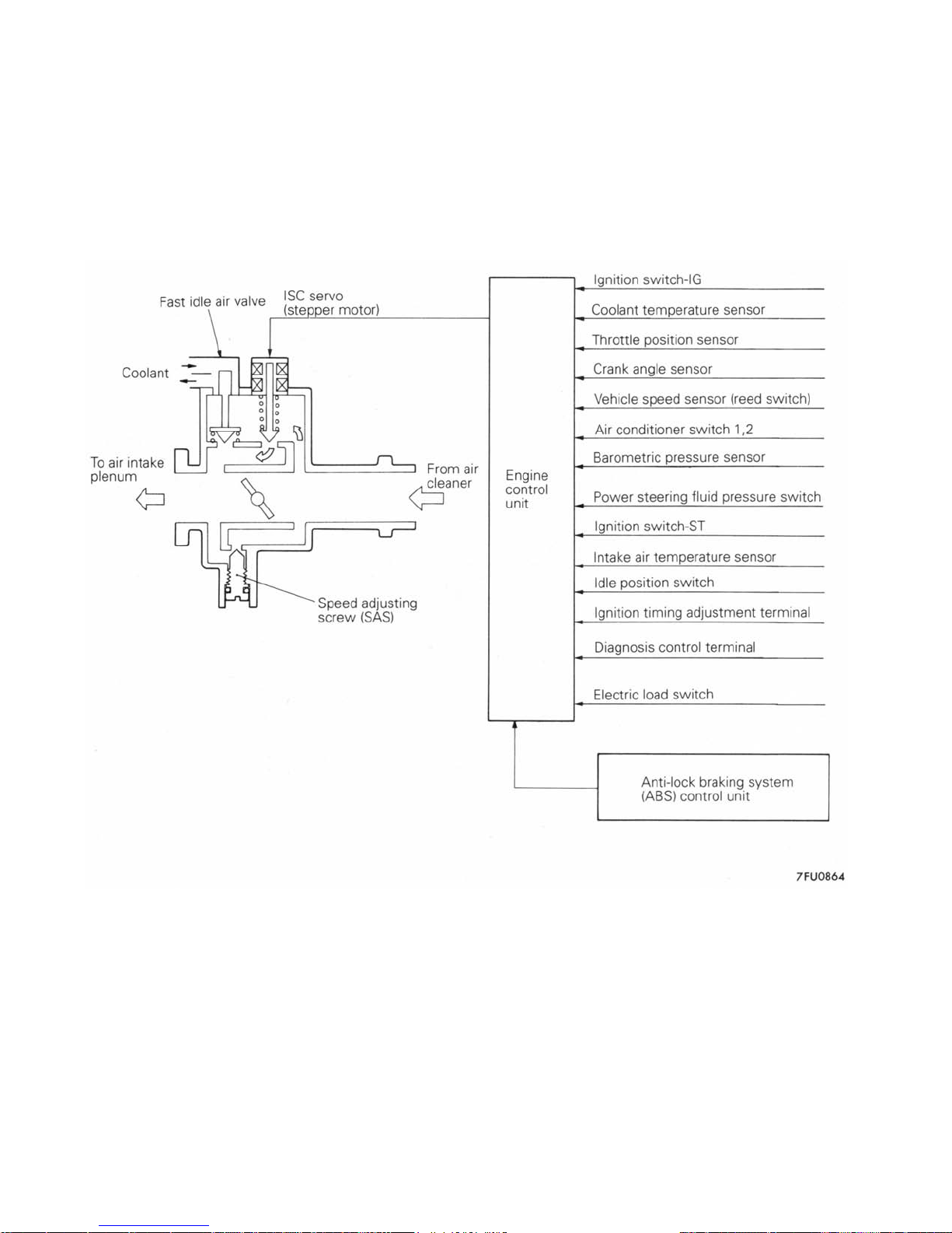
IDLE SPEED CONTROL (ISC)
Control System
(1) Stepper motor (STM) position control with the anti-
lock braking system (ABS) function was added.
SYSTEM CONFIGURATION DIAGRAM
(2) Other controls are basically the same control system
as in the conventional 6G72 engine.

ENGINE - Control System
1-21
MECHANICAL DASHPOT
There is a mechanical dashpot which gradually closes the throttle
valve from a set opening during deceleration to improve deceleration
feeling.

1-22
ENGINE -
Control System
IGNITION TIMING AND ON TIME CONTROL
The ignition timing and on time control methods are
basically the same as those used before.
SYSTEM CONFIGURATION DIAGRAM
ENGINE - Control System
POWER SUPPLY AND FUEL PUMP CONTROL
1-23
Power supply control to the injector, air flow sensor, ISC
servo, etc. is the same as in the conventional 6G72
engine.
Fuel pump control for controlling power supply to the
fuel pump is also the same as in the conventional 6G72
engine.
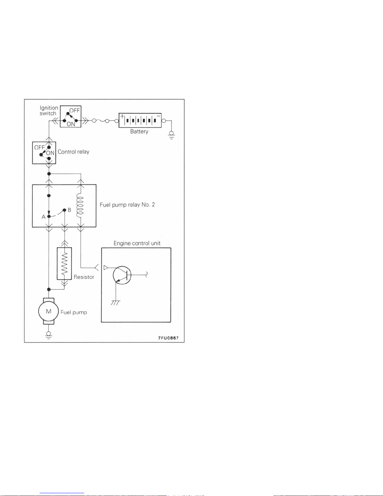
FUEL PUMP DISCHARGE
VOLUME CONTROL
Fuel pump discharge volume is controlled in two steps
according to the amount of intake air (engine load) in 1
cylinder in 1 cycle for improved reliability of the fuel
pump. When the amount of intake air in this 1 cylinder 1
cycle is small (engine load is low), the engine control
unit turns on the power transistor so current flows in the
coil of fuel pump relay
changes form A to B (refer to the figure on the left.), and
current flows via the resistor to the fuel pump motor. The
supply voltage to the fuel pump is reduced since the
voltage is lowered by the resistor, pump speed falls and
the amount of fuel discharged from the fuel pump is
reduced.
When the amount of intake air in this 1 cylinder 1 cycle
is large (engine load is high), the engine control unit
turns off the power transistor and changes the relay
switch from B to A (refer to the figure on the left.). As a
result, voltage drop due to the resistor increases, pump
speed rises and the amount of fuel discharged from the
fuel pump increases.
No.2. As a result, the relay switch

1-24
TURBO METER CONTROL
FUEL - Control System
The turbo meter is a current type meter. The engine
control unit receives the intake air volume signal from
the air flow sensor and the rpm signal from the crank
angle sensor and calculates the engine load.
Duty Ratio
The duty ratio is defined as ON time ratio
When the duty ratio increases, average current that flows to the
turbo meter also increases so that the turbo meter indicates higher
value.
When the duty ratio is decreased, the turbo meter indicates smaller
value.
Then, the unit determines the duty ratio according to the
load and drives the turbo meter.
Duty ratio ~=
Load ~=
T2/T1
of a 33.3 Hz pulse.

TURBO PRESSURE CONTROL
FUEL - Control System
1-25
Turbo pressure used in the waste gate actuator is
controlled by duty control of the waste gate solenoid
valve. As a result, turbo pressure corresponding to
driving conditions can be obtained.
The engine control unit turns the power transistor in the unit on and,
when normal current (duty 100%) flows in the waste gate solenoid
valve coil, the waste gate solenoid valve does not open if turbo
pressure does not rise above the set pressure of the waste gate
actuator spring since some of the turbo pressure used in the waste
gate actuator leaks out.
On the other hand, when current does not flow in the waste gate
solenoid valve coil (duty 0%), the waste gate valve opens if turbo
pressure rises to the set pressure of the waste gate actuator spring
since no pressure leaks out.
Consequently, by using duty control for the waste gate solenoid
valve, turbo pressure can be controlled in a range from 00/0 to
100% duty.
This duty control is performed in cycles of approximately 60 ms.

1-26
FUEL - Control System
FUEL PRESSURE CONTROL
FUEL SYSTEM-FUEL PRESSURE CONTROL VALVE (Refer to P. 1-12)
AIR FLOW SENSOR (AFS) FILTER RESET CONTROL, AIR CONDITIONER
RELAY CONTROL
These controls are the same as those for the conventional 6G72 engine.

ENGINE -
Control System
SELF DIAGNOSIS SYSTEM
The following items have been made more complete.
(1) Check engine lamp ON items
(2) Self diagnosis items
CHECK ENGINE LAMP CONTROL
The check engine lamp ON items are shown in the
following table.
Oxygen sensor <Except for General Export and GCC> Barometric pressure sensor
Air flow sensor (AFS) Detonation sensor
Intake air temperature sensor Ignition timing adjustment signal*
Throttle position sensor Injector
Coolant temperature sensor Ignition coil, power transistor unit
(3) Service data items to be transferred to multi-use
tester
(4) Actuator test items by multi-use tester
1-27
Crank angle sensor
Cam position sensor Engine control unit
Remarks
*:
The check engine lamp lights even when the ignition timing adjustment terminal is short-circuited to the earth during an
injection timing adjustment.
SELF DIAGNOSIS FUNCTIONS
(1) Arrangements have been made to allow changeover
of the diagnosis mode from DIAGNOSIS 1 mode to
DIAGNOSIS 2 mode by sending a diagnosis mode
changeover signal from the multiuse tester.
In the DIAGNOSIS 2 mode, note that the time from
when a fault is detected to when it is determined as a
fault is shorter than in the DIAGNOSIS 1 mode (4
Æ
seconds
Code Diagnosis item Description DIAGNOSIS
No. 2 Mode
11 Oxygen sensor (Rear bank) Malfunction of the air/fuel ratio control system
1 second).
<Except for General export and GCC> Open or short circuit in the oxygen sensor circuit
When the multi-use tester is disconnected from the
diagnosis connector, all fault codes will' be cleared
from the memory, and the DIAGNOSIS 2 mode will
be changed back to the DIAGNOSIS 1 mode.
(2) The other functions remain unchanged.
(3) The diagnosis items are as shown in the following
table.
-
12 Air flow sensor Open or short circuit in sensor and allied circuit Valid
13 Intake air temperature sensor Open or short circuit in sensor and allied circuit Valid
14 Throttle position sensor Abnormal sensor output Valid

*
1-28
Code Diagnosis item Description DIAGNOSIS
No.
21
Coolant temperature sensor
22
Crank angle sensor Abnormal sensor output Valid
23
Cam position sensor Abnormal sensor output Valid
24
Vehicle speed sensor (reed switch) Open or short circuit in sensor circuit Valid
25
Barometric pressure sensor Open or short circuit in sensor circuit Valid
31
Detonation sensor Abnormal sensor output Valid
ENGINE - Control System
Open or short circuit in sensor and allied circuit Valid
•
Increased connector contact resistance
•
2 Mode
36*
Ignition timing adjustment signal Short circuit in ignition timing adjustment signal line
39
Oxygen sensor (Front bank) Malfunction of the air/fuel ratio control system
<Europe, Hong Kong and Singapore> Open or short circuit in the oxygen sensor circuit
41
Injector (Rear bank) Open circuit in injector and allied circuit Valid
44 1-4 cylinder ignition coil, power
transistor unit generated)
52 2-5 cylinder ignition coil, power
transistor unit generated)
53 3-6 cylinder ignition coil, power
transistor unit generated)
-
Normal
: Fault code No. 36 is not memorized.
SERVICE DATA OUTPUT
The service data output items are shown in the following
table.
Item No. Service data item Unit
Abnormal ignition signal (No coil primary voltage Valid
Abnormal ignition signal (No coil primary voltage Valid
Abnormal ignition signal (No coil primary voltage Valid
-
-
-
-
11
12
13
14
16
17
18
21
22
25
26
Oxygen sensor output (Rear bank) <Except for General Export and GCC> mV
Air flow sensor output Hz
Intake air temperature sensor output °C
Throttle position sensor output mV
Battery voltage V
Mixture adjusting screw (variable resistor) <GCC, general export> ON - OFF
Cranking signal (ignition switch-ST) ON - OFF
Coolant temperature sensor output °C
Crank angle sensor output RPM
Barometric sensor output mmHg
Idle position switch ON - OFF

ENGINE - Control System
1-29
Item No. Service data item Unit
27 Power steering fluid pressure switch ON - OFF
28 Air conditioner switch ON - OFF
33 Electric load switch ON - OFF
34 Air flow sensor reset signal ON - OFF
36 Ignition timing adjustment mode ON - OFF
37 Volumetric efficiency
38 Crank angle sensor output (readable at 2,000 rpm or less) RPM
39 Oxygen sensor output (Front bank) <Europe, Hong Kong and Singapore> mV
41 Injector drive time (Rear bank) mS
44 Ignition advance angle value ºBTDC,ºATDC
45 ISC stepper motor position STEP
47 Injector drive time (Front bank) mS
49 Air conditioner relay ON - OFF
ACTUATOR TESTS
The actuator test items are shown in the following table.
NOTE
The items that have been added to the conventional
system are shown in bold letters.
I
%
Item No. Actuator test item
01 NO.1 injector: OFF
02 NO.2 injector: OFF
03 NO.3 injector: OFF
04 NO.4 injector: OFF
05 NO.5 injector: OFF
06 NO.6 injector: OFF
07 Fuel pump: ON
08 Purge control solenoid valve: ON <Europe, Hong Kong and Singapore>
09
10 EGR control solenoid valve: ON <Except for Australia>
12
13
17 Ignition timing: 5º BTDC
Fuel pump relay No.2: ON (Current flows via the resistor)
Fuel pressure control valve: ON
Waste gate solenoid valve: ON
OIL LEVEL WARNING SYSTEM
This system is the same as that of the conventional 6G72 engine.

/
1-30
ENGINE - Emission Control System
EMISSION CONTROL SYSTEM
The emission control system is basically the same as
that used in the 6G72 engine fitted to the PAJERO
MONTERO. However, the following additions have been
made to the system in vehicles for Europe, Hong Kong
and Singapore only.
(1)
Oxygen sensors and a front catalytic converter have
been added to reduce the level of exhaust gas
emissions.
(2)
The evaporative emission control system has been
improved as shown below. The fuel vapour intake
amount from the canister has been increased so
. System
Europe Singa- Australia GCC Export
Crankcase ventilation system x x x x x
Evaporative emission control Electronics controlled type
system (Europe, Hong Kong and
x x x x
Applicable destination
Hong
Kong, General
pore
Catalytic converter x x x
that the amount of vapour that escapes to the
atmosphere has been reduced.
• When driving with a low to medium load on the
engine, the fuel vapour absorbed by the,
canister is drawn into the P port of the throttle
body in the same way as in engines without
turbocharger.
• When driving with a high load on the engine, the
purge control valve opens and the fuel vapour
absorbed by the canister is drawn into the air
intake hose.
Remarks
-
Singapore)
Vacuum controlled type
(Australia and GCC)
-
-
Three way cataIyst
Air fuel ratio closed loop control x x x
Exhaust gas recirculation system x x
Emission Control System Diagram
<Europe, Hong Kong and Singapore>
-
-
x x Electronics controlled type
Oxygen sensor signal used
-

1-31
<Australia>
ENGINE - Emission Control System
<GCC and General Export>

1-32 ENGINE - Cruise Control System
CRUISE CONTROL SYSTEM
The cruise control system makes constant-speed driving
possible at a speed designated by the driver [within a
range of approx. 40 - 200km/h (25 125m ph)] without
depressing the accelerator pedal.
NOTE
The cruise control system is basically the same as the
system equipped in the SIGMA.

2-1
POWER-
TRANSMISSION
COMPONENTS
CONTENTS
CLUTCH …………………………………………………..
Specifications ………………………………................. 2
Clutch Booster ………………………………. .............. 3
MANUAL TRANSMISSION .......................................... 4
Specifications ............................................................ 4
Sectional View ........................................................... 5
W5MG1 4WD Transmission ...................................... 6
Transmission Control ............................................... 10
PROPELLER SHAFT .................................................11
Specifications ..........................................................11
2
FRONT AXLE .............................................................. 12
Specifications ..........................................................12
REAR AXLE ................................................................ 13
Specifications ..........................................................13
Axle Shaft ................................................................13
Drive Shaft ...............................................................13
Differential ...............................................................15
Differential Support ..................................................16

2-2
POWER-TRANSMISSION COMPONENTS - Clutch
CLUTCH
The clutch is the dry single-plate diaphragm type;
A hydraulic type with clutch booster is used for the
clutch control.
Some models are equipped with a clutch damper in
the clutch tube to make changes in hydraulic pressure smoother when the clutch is engaged and to reduce the maximum value for the clutch input torque.
SPECIFICATIONS
Items Specifications
Clutch operating method Hydraulic type
Clutch disc
Type Single dry disc type
Facing diameter
0.0. x 1.0. mm (in.) 250 x 160 (9.8 x 6.3)
Clutch cover assembly
Type Diaphragm spring strap drive type
Setting load N (kg,lbs.) 9,200 (920, 2,024)
Clutch release cylinder
1.0. mm (in.) 19.05 (3/4)
Clutch master cylinder
1.0. mm (in.) 15.87 (5/8)
Clutch booster
Type Vacuum type, single
Effective dia. of power cylinder mm (in.) 101 (4.0)
Boosting ratio 1.7 [at 110 N (11 kg, 24 Ibs.)]
[Clutch pedal depressing force]
Vacuum tank
Capacity dm3 (U.S. qts., Imp. qts.) 1.2 (1.27, 1.06)
Vacuum pipe
Check valve
Vacuum hose
Clutch master cylinder
Vacuum pipe
Clutch release
cylinder
Clutch tube
clutch hose
Pedal support bracket
Clutch booster
Clutch vacuum tank
Clutch pedal

A 4" single type clutch booster is used to reduce the
force to depress the pedal. The structural operation
of the clutch booster is basically the same as with the
brake booster.
Push rod
Booster return spring
Negative pressure chamber
/
Diaphragm
Booster piston
Valve plunger
Poppet
'Reaction disc
Air chamber
Operating rod
Filter
Valve plunger stopper key
08F0007

2-4
POWER-TRANSMISSION COMPONENTS - Manual Transmission
MANUAL TRANSMISSION
The manual transmission is a W5MG1 transmission. A cable type floor shift is used for transmission control. The
W5MGI is a transmission that has been newly developed to respond to the high output and high torque of the
6G72-DOHC-Turbo engine.
SPECIFICATIONS
Items Specifications
Transmission model W5MG1
Type 5-speed constant-mesh cable controlled type
Gear ratio (number of gear teeth)
1 st 3.071 (43/14)
2nd 1.739 (40/23)
3rd 1.103 (32/29)
4th 0.823 (28/34)
5th 0.659 (31/47)
Reverse 3.076 (40/13)
Primary reduction ratio (number of gear teeth) 1.375 (44/32)
Front differential gear ratio (number of gear teeth) 2.888 (52/18)
Transfer gear ratio (number of gear teeth) 0.814 (22/27)
Torque split ratio Front/Rear 45/55
Speedometer gear ratio Drive/Driven 27/36

POWER-TRANSMISSION COMPONENTS -
g
p
g
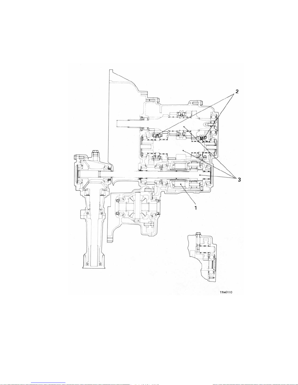
SECTIONAL VIEW
W5MG1
Manual Transmission 2-5
1. Clutch housing 14. 5th speed gear
2. 1st speed gear 15. Center shaft
3. 1st-2nd synchronizer hub 16. Viscous coupling
4. 2nd speed gear 17. Center differential
5. Transaxle case 18. Reverse idler
6. 3rd speed gear 19. Front differential
7. 3rd-4th synchronizer hub 20. Transfer driven bevel gear
8. 4th speed gear 21. Transfer drive bevel gear
9. 5th speed gear input shaft 22. Transfer case
10 5th-reverse synchronizer hub 23. Front output shaft
11 Rear cover 24. Intermediate shaft
12 In
13 Reverse
ut shaft retainer 25. Input shaft
ear
ear

A
2-6
POWER-TRANSMISSION COMPONENTS - Manual Transmission
W5MG1 4WD TRANSMISSION
The W5MG1 is a 3-shaft, full time 4WD transmission.
It is not only a planetary gear type differential with the
center differential on the NO.3 shaft used, but also a
viscous coupling acting as a differential limiter that is
built into the front and rear output shafts.
The gear meshing method is a constant-mesh method also used for reverse.
The reverse idler gear is on the rear cover.
A double-cone synchronizer is used for 1st speed and
2nd speed for improved shift feeling.
double-mesh prevention device using an interlock
plate and a reverse mis-shift prevention device using
a stopper plate are adopted in the shift control
system.
The construction and operation of the double-mesh
prevention device, and reverse mis-shift prevention
device are basically the same as on the 4WD transmission previously used.
PLANETARY GEAR TYPE CENTRE DIFFERENTIAL
Outer pinion
Viscous coupling
Front output shaft
Front output
Centre differential case (ring gear)
09F0126
The centre differential has the construction shown in the figure
above, and is made up of the differential case (integral part of
ring gear), outer pinions (3 pc.), inner pinions (3 pc.), carrier, sun
gear, front output shaft, centre shaft and viscous coupling. Drive
force input from the outside of the differential case is transmitted
to the outer pinions and inner pinions by the ring gear on the
inside of the case, from there is distributed to the sun gear and
carrier to be transmitted to the front output shaft and centre shaft.
Furthermore, since there is a viscous coupling built in this centre
differential, when a rotational speed difference arises between
the front output shaft and centre shaft, differential control torque
is redistributed according to that difference so that the ideal drive
force is always maintained.
In addition, unequal torque distribution is used in this centre
differential.

POWER-TRANSMISSION COMPONENTS - Manual Transmission 2-7
A
The distribution of the drive force to the carrier and sun gear in a
planetary gear type differential is determined by the number of teeth
on the ring gear and sun gear.
Here is the figure of the velocity diagram if the number of teeth on
the ring gear is Zr and the number of teeth on the sun gear is Zs.
The carrier is considered to be fixed, the ring gear and sun gear
revolve in the same direction, and the sun gear rotates Zr/Zs for one
rotation of the ring gear. The figure on the left shows the velocity
diagram for such a case.
ccording to the velocity diagram, the result is as follows if we
consider a state of balance with the ring gear in the center when the
ring gear and sun gear rotate at the same speed.
If
Tr: Ring gear input torque
Ts: Sun gear output torque (front output)
Tc: Carrier output torque (rear output)
Then
(1) Tr = Tc+Ts
(2) Tc x Zs = (Zr - Zs) x Ts
From (1) and (2)
Ts
= Zs/Zr
x Tr
Tc
= (Zr-Zs)/Zr
Ts:Tc = Zs: Zr - Zs = Front: Rear
With the W5MG1, Zr = 60 and Zs = 27, so Zr - Zs = 33.
Front: Rear = 27: 33 = 45 : 55.
x Tr

2-8 POWER-TRANSMISSION COMPONENTS - Manual Transmission
A
DOUBLE-CONE SYNCHRONIZER
1st speed gear
Synchronizer cone
The double-cone synchronizer used for 1st speed and
2nd speed are made up, as shown in the figure above,
of the speed gear, clutch gear (welded to the speed
gear), inner synchronizer ring, synchronizer cone, outer
synchronizer ring, synchronizer hub, synchronizer
sleeve, synchronizer key, etc.
The inner synchronizer ring touches liner of the synchronizer cone inner surface at the outer cone surface
and is coupled to the outer synchronizer ring by the
projections (3 locations) on the synchronizer hub. The
synchronizer cone touches the inner synchronizer ring
and outer synchronizer ring at the inner surface liner and
Outer synchronizer ring
Synchronizer sleeve
key 2nd speed
Synchronizer hub
Synchronizer
gear
09F0123
outer surface liner respectively, and is coupled with the
clutch gear by the projections (6 locations) on the speed
gear.
The outer synchronizer ring touches the outer surface
liner of the synchronizer cone at the inside cone surface
and is coupled to the synchronizer hub by the
projections (3 locations) on the outer circumference. In
other words, the inner synchronizer ring and outer
synchronizer ring become one
nit with the synchronizer
~
hub and rotate, and the synchronizer cone becomes one
unit with the speed gear and rotates as they touch each
other.
When the shift lever is moved toward 1st speed, the shift fork moves
the synchronizer sleeve to the left.
t this time, since the ball in the synchronizer key is pressed into the
groove of the synchronizer sleeve by the spring, the synchronizer
sleeve and key are joined and move to the left. As a result, the outer
synchronizer ring is pressed to the left, friction torque is generated
between the synchronizer cone and outer synchronizer ring and
inner synchronizer ring, and the 1st speed gear and synchronizer
hub (intermediate shaft) begin to synchronize.
Then, when the shift fork moves to the left, the synchronizer sleeve
pushes the synchronizer key spring tight, crosses over the
synchronizer key and moves to the left.

2-9
POWER-TRANSMISSION COMPONENTS - Manual Transmission
Then the chamfer of the outer synchronizer ring spline and the
chamfer of the synchronizer sleeve spline come in contact.
As a result of this contact, a major pushing force is generated in the
outer synchronizer ring, the friction torque between the synchronizer
cone and outer synchronizer ring and inner synchronizer ring
increases, and then the difference in rotational speed of the 1st
speed gear and the synchronizer hub disappears.
Under these conditions, since the synchronizer sleeve is pressed to
the left, the synchronizer sleeve spline and outer synchronizer ring
spline mesh.
Also, when the synchronizer sleeve moves to the left, the
synchronizer sleeve spline chamfer comes in contact with the clutch
gear spline chamfer of the 1st speed gear, and then the clutch gear
spline and synchronizer sleeve spine mesh to complete the shift to 1
st speed.

•
2-10
POWER-TRANSMISSION COMPONENTS - Manual Transmission
TRANSMISSION CONTROL
• There are vibration-prevention rubber pieces
mounted on the transaxle side of the shift cable
and selector cable, and on the shift lever
assembly side to prevent transmission of fine
vibrations to the body.
• The eye end on the shift lever assembly of the
shift cable has a double structure, a combination
of a resin bushing and rubber bushing, and this
not only provides smooth movement of the shift
cable but also prevents transmission of vibration
to the shift lever assembly, improving the shifting
feel.
Vibration-prevention
rubber pieces
A combination of a wave washer and thrust
washer are used in the shift lever shaft of the shift
lever assembly, and this not only reduces the
looseness in the direction of the lever shaft but
also elastically supports the shift cable on the
cable bracket of the shift lever assembly, reducing
shaking of the shift lever.
• Shaking of the shift lever caused when
accelerating and decelerating due to bent of the
shift and selector cables is reduced.
Shift cable
Selector cable
Shift lever assembly
Shift lever
09F0074

f
POWER-TRANSMISSION COMPONENTS - Propeller Shaft 2-11
PROPELLER SHAFT
The propeller shaft is a 3-section 4-joint shaft with 2
center bearings. This division into 3 sections
increases the vibration frequency characteristics o
the shaft bending, and reduces vibration and noise
when driving at high speed. The joints for connecting
each part of the propeller shaft are as follows; No.1,
No.2 and No. 4 joints are cross type universal joints
and No.3 joint is a Lobro joint (LJ) that can slide and
has small friction in the direction of the shaft. This
structure helps reducing torque fluctuation, vibration
and noise. Furthermore, the rear propeller shaft is a
vibration-control type shaft (using rubber) with an
inner tube inserted in the outer tube to reduce
vibration and noise from the drive train.
SPECIFICA TIONS
Item Specification
Propeller Length x 0.0. Front 673.5 x 65 (26.52 x 2.56)
shaft mm (in.) Center 662.5 x 65 (26.08 x 2.56)
Universal Type No.1 Cross type
joint No.2 Cross type
Type 4-joint propeller shaft
Rear 555.5 x 75 (21.87 x 2.95)
No.3 Constant velocity type (L6bro joint, LJ95)
No.4 Cross type
Lubrication Pre-packed
Size mm (in.) Cross type joint 17.996 (0.7085)
journal 0.D.
.
Constant velocity 99.73 (3.93)
joint 0.D.
NOTE
Propeller shaft length indicates the length between center points of each joint.
CONSTRUCTION DIAGRAM
Lobro joint
Front propeller shaft
Center bearing
Center propeller shaft
Center bearing
10F0007

•
2-12 POWER-TRANSMISSION COMPONENTS - Front Axle
FRONT AXLE
The drive shaft is of the Birfield joint (B.J.)-tripod joint
(T.J.) type. This type features high power transmission
efficiency and low vibration and noise. It has the
following features.
B.J.
• Large operating joint angle
• 'Compact size and decreased space req'ulrements
T.J.
• Axially slidable
• Smaller sliding friction
• The B.J. joint boot is made of highly-durable resin to
provide improved reliability
SPECIFICATIONS
Item Specifications
Hub, knuckle
Bearing type Unit ball bearing
Drive shaft
Joint type Outer B.J.
Length (between joints) x 0.D.
L.H. mm (in.) 419 x 26
R.H. mm (in.) 391 x 26
The B.J. joint boot is made of highly-durable resin to
provide improved reliability
Inner T.J.
(16.5 x 1.02)
(15.4 x 1.02)
Inner shaft
Bracket
kn,uckle
Centre bearing
T.J.
Resin boot
B.J.
Unit ball bearing
11F0048

POWER-TRANSMISSION COMPONENTS - Rear Axle 2-13
REAR AXLE
The differential carrier and axle housing have been
separated from each other, and T.J. and B.J. drive
shafts arranged in between. They drive the axle shafts.
The axle shaft is supported by ball bearings (inner and
outer) in the axle housing and are coupled with the drive
SPECIFICA TIONS
Items Specifications
Axle shaft
Type Semi-floating type
Shaft dimensions
Outer bearing portion dia. mm (in.) 35 (1.38)
Inner bearing portion dia. mm (in.) 28 (1.1 0)
Center portion dia. mm (in.) 34.5 (1.36)
Overall length mm (in.) 245.4 (9.7)
Bearing
0.D. x I.D. Outer mm (in.) 72 x 35 (2.83 x 1.38)
Drive shaft
Joint type Outer B.J.
Length (joint to joint) x diameter mm (in.) 395 x 28 (15.6 x 1.10)
Differential
Reduction gear type Hypoid gear
Reduction ratio 3.545
Differential gear type and configuration
Side gear Straight bevel gear x 2*
Pinion gear Straight bevel gear x 4
Number of teeth
Drive gear 39
Drive pinion 11
Side gear 16
Pinion Gear 10
Bearing
0.D. x I.D. Side mm (in.) 82.500 x 45.242 (3.25 x 1.78)
Final drive gear backlash adjustment method Screw type
Inner mm (in.) 58 x 28 (2.28 x 1.10)
Inner T.J.
Front mm (in.) 68.263 x 30.163 (2.69 x 1.19)
Rear mm (in.) 76.200 x 36.513 (3.00 x 1.44)
shaft with the companion flange in between.
The front of the differential carrier is supported elastically
on the rear suspension crossmember via the differential
support and the rear side via the differential support
member.
*.
Denotes the gear (L.H.) which is in a single body with the viscous coupling.
T.J.
Differential carrier
Drive shaft
B.J
Companion flange
.
Axle shaft
Trailing arm
(Axle housing)
11 N0002

A
2-14 POWER-TRANSMISSION COMPONENTS - Rear Axle
AXLE SHAFT
The axle shaft is a semi-floating type supported by
ball bearings (outer and inner) in the housing.
On models with the anti-lock braking system, there is
a wheel speed sensing rotor on the axle shaft.
Companion flange
B.J.
Trailing arm
xle shaft
DRIVE SHAFT
A B.J.-T.J. type constant velocity joint is used in the
drive shaft, featuring the same good transmission efficiency, low vibration and low noise as the front drive
shaft. On the axle shaft side there is a B.J. type joint
that can bend to a great degree to match movement
of the suspension and on the differential carrier side
there is a
amount in the shaft direction with little sliding friction.
T.J.
type joint that can slide to a large
To prevent mud that may be deposited around the
bearing (outer), a dust shield has been provided.
Dust shield
11N0009
Rotor
On the axle shaft side, they are coupled with the
companion flange in between. On the differential side,
they are spline coupled with the side gears, the right
and left drive shafts are different in length. In addition,
T.J.
the
side of the drive shaft (R.H.) is two-stage
serration coupled.
<L.H.>
<R.H.>
Two-stage
serration
11F0006

V
POWER-TRANSMISSION COMPONENTS - Rear Axle 2-15
DIFFERENTIAL
The differential uses lower friction torque bearings
and oil seals to improve power performance and fuel
consumption.
For faster differential cooling and higher reliability
during high speed operation, a differential carrier with
cooling fins has been adopted.
A speed difference responsive viscous coupling type
Cooling fins
limited slip differential which provides outstanding
performance during operation on a muddy surface
has been established.
There is a 4-wheel steering (4WS) oil pump on the
top of the differential carrier.
11 F0001
ISCOUS COUPLING TYPE LIMITED SLIP DIFFERENTIAL
While the conventional mechanical type limited slip
differential uses a cam (differential pinion shaft) and
disc equipment composed of a friction
I
plate, disc and
spring seat in limiting the differential, the viscous
Front wheel
Center differential
(viscous coupling)
Front differential
Rear wheel
Limited slip differential
assembly
Differential
Differential limiting
section
(viscous coupling)
11P0066
coupling type limited slip differential limits the
differential by use of a viscous coupling equipment
consisting of outer and inner plates and silicone oil.

2-16 POWER-TRANSMISSION COMPONENTS - Rear Axle
DIFFERENTIAL SUPPORT
The front and rear of the differential carrier are mounted
on the suspension crossmember by the differential
Differential support (R.H.)
Differential support (L.H.)
supports and differential support member. It is elastically
mounted via a bushing.
Differential
support member
11N0038

3-1
DRIVE-CONTROL
COMPONENTS
CONTENTS
SUSPENSION ............................................................... 2
Features .................................................................... 2
FRONT SUSPENSION ................................................. 3
Features .................................................................... 3
Specifications ............................................................ 3
Camber Adjustment Mechanism ............................... 4
REAR SUSPENSION ................................ .................. 5
Features ................................................. .................. 5
Specifications ......................................... .................. 5
Crossmember and Crossmember
Support Bushing ....................................................... 6
ELECTRONIC CONTROL SUSPENSION
(E CS) ..........................................................................................7
Specifications .............................................................7
Main Parts and Their Functions ................................9
System Block Diagram ..............................................9
Features of Each Mode ...........................................10
Features of Each Control ......................................... 10
Structure and Operation ......................................... 11
4 WHEEL STEERING (4WS) SYSTEM ......................27
Specifications ..........................................................27
System Construction ............................................... 28
Rear Wheel Steering Oil Pump, .............................. 29
Control Valve ........................................................... 29
Power Cylinder ........................................................ 29
BRAKES ..................................................................... 30
Features .................................................................. 30
SERVICE BRAKES ....................................................31
Specifications ......................................................... 31
Front Disc Brake ..................................................... 32
Rear Disc Brake ...................................................... 33
ANTI-LOCK BRAKE SYSTEM (ABS) ........................ 34
System Drawing ...................................................... 35
ABS Electric Diagram .............................................. 36
ABS Hydraulic Function Drawing ........................... 37
Sensor ..................................................................... 38
Actuator ................................................................... 38
Electronic Control Unit (ECU) ................................. 39
WHEEL AND TYPE .................................................... 21
Specifications ......................................................... 21
POWER STEERING ....................................................22
Specifications ..........................................................22
Steering Wheel and Column .................................. 23
Oil Pump ................................................................. 26
PARKING BRAKE ...................................................... 41

f
3-2 DRIVE CONTROL COMPONENTS - Suspension
SUSPENSION
A 4 wheel independent suspension system has been
adopted, with the front suspension of a MacPherson
strut type, and the rear suspension of a double
FEATURES
wishbone type. In addition, 4WS is equipped in all
models.
Improved steering stability
and riding comfort
Improved riding comfort
Improved serviceability
1. Adoption of electronic control suspension (ECS)
2. Adoption of 4 wheel independent suspension
3. Adoption of wide tread tyres
4. Optimization of suspension geometry
5. Adoption of pillow ball type stabilizer links
6. Optimization of spring characteristics of suspension bushing
7. Adoption of a liquid filled bushing as the front suspension
lower arm bushing
1. Adoption of double elastic supported suspension members
2. Optimization of coil spring offset amount
3. Adoption of large-sized bump rubber
1. Full realization of sel
2. Adoption of a camber adjustment mechanism in the front
suspension
3. Adoption of camber and toe-in adjustment mechanisms in the
rear suspension
-diagnosis for ECS system

•
DRIVE CONTROL COMPONENTS - Front Suspension 3-3
FRONT SUSPENSION
Perimeter type (crossed parallel) suspension members are used in the front suspension to improve driving stability.
FEATURES
• Reduction of vibration and noise because the entire suspension system is elastically supported by
rubber bushings.
• Ideal wheel alignment for superior driving stability
and riding comfort.
• Adoption of anti-driving geometry for outstanding
driving stability.
SPECIFICATIONS
Items Specifications
Suspension system MacPherson strut with coil spring and compression
Camber 0° ± 30'
Caster 3°55' ± 30'
Toe-i n mm (in.)
Coil spring
Wire dia x 0.D. x free length mm (in.)
Vehicles for Europe 15.4 x 185.4 x 293 (0.61 x 7.30 x 11.54)
Vehicles for General Export, GCC and Australia 15.7 x 185.7 x 301.5 (0.62 x 7.31 x 11.87)
Coil spring identification colour
Vehicles for Europe Pink x 2
Vehicles for General Export, GCC and Australia Blue x 1
Spring constant N/mm (kg / mm, Ibs. / in.) 39 (3.9, 218)
Shock absorber
Type Hydraulic, cylindrical double acting type
Stroke mm (in.) 150 (5.91 )
Damping force [at 0.3 m/sec. (0.984 ft./sec)]
Expansion N (kg, Ibs.) Hard: 2,650 (265, 584)
Contraction N (kg, Ibs.) Hard: 1,200 (120, 265)
Stabilizer bar
Mounting method Pillow ball type
0.D.
Adoption of negative offset geometry for out-
standing braking stability.
• Offset coil springs for outstanding riding comfort.
• Improved serviceability due to the adoption of a
camber adjustment mechanism.
rod type
o ± 3 (0 ± 0.12)
Medium: 1,650 (165, 363)
Soft: 650 (65, 143)
Medium: 1,150 (115, 253)
Soft: 1,000 (100, 220)
mm (in.) 23 (0.91)

3-4 DRIVE CONTROL COMPONENTS - Front Suspension
A
12F0082
Strut assembly
Stabilizer bar
No.2 crossmember
Right member
No.1 cross member
Left member
Lower arm
CAMBER ADJUSTMENT MECHANISM
It is possible to adjust the camber by turning the strut lower mounting bolt.
Section A-A
djusting cam
(eccentric bolt)
12FOO26
12F0028

•
DRIVE CONTROL COMPONENTS - Rear Suspension 3-5
REAR SUSPENSION
FEATURES
• Independent suspension for sure grip on the
ground.
• Arm arrangement to minimized camber variations
against the ground.
• Low friction design that does not put bending
force on the damper.
SPECIFICATIONS
Items Specifications
Suspension system Double-wishbone type
Camber -0º10' ± 30'
Toe-i n mm (in.) 0.5 ± 2.5 (0.02 ± 0.10)
Coil spring
Wire dia. x 0.D. x free length mm (in.) 12.2 x 117.2 x 379.3 (0.48 x 4.61 x 14.93)
Coil spring identification colour Blue x 2
Spring constant N/mm (kg / mm, Ibs. / in.) 28.0 (2.8, 157)
Shock absorber
Type Hydraulic, cylindrical double-acting type
Stroke mm (in.) 203 (8.0)
Damping force [at 0.3 m/sec. (0.984 ft./sec.)]
Expansion N (kg, Ibs.) Hard: 1,710 (171,377)
Contraction N (kg, Ibs.) Hard: 1,010 (101, 223)
Stabilizer bar
Mounting method Pillow ball type
0.D. mm (in.) 22 (0.86)
Anti-lift geometry to control tail lifting when brak-
ing.
• Improved quietness due to differential carrier
double elastic support structure.
Medium: 1,160 (116, 256)
Soft: 560 (56, 123)
Medium: 880 (88, 194)
Soft: 670 (67, 148)

r
3-6 DRIVE CONTROL COMPONENTS - Rear Suspension
Crossmember
Upper arm
Trailing arm
Differential support
CROSSMEMBER AND CROSSMEMBER SUPPORT BUSHING
The crossmember not only receives input from each
arm and link as a real suspension crossmember but
also supports the rear differential.
The crossmember support bushing provides bette
isolation of high frequency noise such as noise from
the differential and gears by using inter-mass to shift
resonance.
Shock absorber
12F0105
12N0014
Front differential support
Rear differential support

DRIVE-CONTROL COMPONENTS - Electronic Control Suspension (ECS)
3
ELECTRONIC CONTROL SUSPENSION (ECS)
The electronic control suspension (ECS) is a system
that automatically switches the damping force characteristics of the four shock absorbers, front and rear, in
three steps (SOFT, MEDIUM and HARD) in response to
driving conditions and the conditions of the road surface.
It is also possible to select two modes (TOUR and
SPORT) according to driver preference. The damping
force is changed by commands from the ECS control
unit; the actuator built into the shock absorbers is
activated and the flow of oil inside the absorbers is
varied.
This system also has a diagnostic function and a failsafe
function for improved serviceability and safety.
SPECIFICATIONS
FRONT SUSPENSION
Items Specifications
Suspension system MacPherson strut with coil spring and compression
Camber 0° ± 30'
Caster 3°55' ± 30'
Toe-i n mm (in.)
Coil spring
Wire dia. x 0.D. x free length mm (in.)
Vehicles for Europe 15.4 x 185.4 x 293 (0.61 x 7.30 x 11.54)
Vehicles for General Export, GCC and Australia 15.7 x 185.7 x 301.5 (0.62 x 7.31 x 11.87)
Coil spring identification colour
Vehicles for Europe Pink x 2
Vehicles for General Export, GCC and Australia Blue x 1
Spring constant N/mm (kg/mm, Ibs./in.) 39 (3.9, 218)
Shock absorber
Type Hydraulic, cylindrical double acting type
Stroke mm (in.) 150 (5.91)
Damping force [at 0.3 m/sec. (0.984 ft./sec.)]
Expansion N (kg, Ibs.) Hard: 2,650 (265, 584)
Contraction N (kg, Ibs.) Hard: 1,200 (120, 265)
Stabilizer bar
Mounting method Pillow ball type
0.D.
mm (in.) 23 (0.91 )
rod type
o ± 3 (0 ± 0.12)
Medium: 1,650 (165, 363)
Soft: 650 (65, 143)
Medium: 1,150 (115, 253)
Soft: 1,000 (100, 220)
-7

3-8 DRIVE-CONTROL COMPONENTS - Electronic Control Suspension (ECS)
REAR SUSPENSION
Items Specifications
Suspension system Double-wishbone type
Camber -0°10' ± 30'
Toe-in mm (in.) 0.5 ± 2.5 (0.02 ± 0.10)
Coil spring
Wire dia. x 0.D. x free length mm (in.). 12.2 x 117.2 x 379.3 (0.48 x 4.61 x 14.93)
Coil spring identification colour Blue x 2
Spring constant N/mm (kg/mm, Ibs./in.) 28.0 (2.8, 157)
Shock absorber
Type Hydraulic, cylindrical double-acting type
Stroke mm (in.) 203 (8.0)
Damping force [at 0.3 m/sec. (0.984 ft./sec.)]
Expansion N (kg, Ibs.) Hard: 1,710 (171, 377)
Contraction N (kg, Ibs.) Hard: 1,010 (101, 223)
Stabilizer bar
Mounting method Pillow ball type
0.D. mm (in.) 22 (0.86)
ECS switch ECS indicator lamp
Front shock absorber (R.H.)
(Built-in F.R. position
detection switch and
F.R. damping force
changeover actuator)
Medium: 1,160 (116, 256)
Soft: 560 (56, 123)
Medium: 880 (88, 194)
Soft: 670 (67, 148)
Steering wheel
angular velocity
sensor
Rear shock absorber (R.H.)
(Built-in R.R. position
detection switch and
R.R. damping force
changeover actuator)
ECS control unit
Vehicle
speed
sensor
Throttle position
sensor
Front shock absorber (L.H.)
(Built-in F.L. position
detection switch and
F.L. damping force
changeover actuator)
Diagnosis
connector
Stop lamp
switch
G-sensor
Rear shock absorber (L.H.)
(Built-in R.L. position
detection switch and
R.L. damping force
changeover actuator)
12F0036

(
DRIVE-CONTROL COMPONENTS - Electronic Control Suspension (ECS) 3-9
MAIN PARTS AND THEIR FUNCTIONS
Parts Function Mounting position
Sensor
ECS switch Control mode selection switch Meter bezel
Steering wheel angular velocity sensor Detects turning direction and Column switch
G-sensor Detects up/down vibration of vehicle
Vehicle speed sensor Detects speed of vehicle Transmission case
Throttle position sensor Detects throttle opening Brake pedal bracket
Stop lamp switch Detects condition of brake pedal Built in shock absorber
Position detection switch Detects damping conditions of
Actuator
ECS indicator lamp Indicates control mode Inside combination meter
Damping force changeover actuator Orifice changeover of inside of Built in shock absorber (x 4)
angular velocity of steering wheel Under front seat (LH)
Throttle body
x 4)
shock absorbers
shock absorber
ECS control unit System control Right side of luggage compartment
Diagnosis connector Output of safe diagnosis code Side of junction block
SYSTEM BLOCK DIAGRAM
ECS switch
Steering wheel angular velocity sensor
G-sensor
Vehicle speed sensor
Throttle position sensor
Stop lamp switch
F.R. position detection switch
F.L. position detection switch
ECS indicator lamp
F.R. damping force changeover actuator
F.L. damping force changeover actuator
R.R. damping force changeover actuator
R.L. damping force changeover actuator
R.R. position detection switch
R.L. position detection switch
Diagnosis connector

(
3-10 DRIVE-CONTROL COMPONENTS - Electronic Control Suspension (ECS)
FEATURES OF EACH MODE
Mode ECS indicator Damping force Features
TOUR Automatic selection • Normal damping force with emphasis on a comfortable ride
SPORT
light
depending on driving
conditions • Safe operation control when making sudden turns or during high
SOFT speed.
MEDIUM- HARD the vehicle and when driving on bad roads is detected
Normally fixed in high • Ideal mode for sporty driving
damping force (HARD) • Normally high damping force with emphasis on safe operation
SOFT)
• Vehicle position control when starting and braking
•
and stability (HARD)
J
FEATURES OF EACH CONTROL

DRIVE-CONTROL COMPONENTS - Electronic Control Suspension (ECS)
STRUCTURE AND OPERATION
SENSOR
ECS Switch
The ECS switch is a return type switch mounted on the meter
bezel.
When the battery is connected and the ignition switch turned ON,
it starts in the TOUR mode. Then, it changes between the TOUR
and SPORT mode each time the mode changeover switch is
pressed.
Steering Wheel Angular Velocity Sensor
The steering wheel angular velocity sensor is made up of 2 photo
interrupters and a slit plate. The photo interrupters are mounted
on the column switch and the slit plate is mounted on the steering
shaft. The slit plate rotates between the photo interrupters so the
light from the LED of photo interrupter is interrupted and passed
through and that is changed by the photo diode to an electric
signal according to the steering wheel angular velocity.
Furthermore, the steering turning direction can also be detected
by the divergence in each 1/4 cycle of the output wave of the
photo interrupters.
3-11
G-Sensor
The G-sensor detects the up/down vibration of the
vehicle and outputs an electric signal. This sensor is
used for controlling a comfortable ride, and it is
mounted under the front seat (LH) where it can
accurately detect the up/down vibration felt
driver.
by
the
Weight and
piezoelectric
element
The inside of the G-sensor are made up of a
piezoelectric ceramic and a weight. The weight adds
extra force on the piezoelectric ceramic depending on
the up/down vibration and the G-sensor outputs an
electric signal according to the vibration due to the
piezoelectric effect.
Amplifier circuit
12F0048
G-sensor output characteristics
12F0003

3-12
DRIVE-CONTROL COMPONENTS - Electronic Control Suspension (ECS)
V
0
ehicle Speed Sensor
The vehicle speed sensor is mounted directly onto the transmission.
For the structure of the vehicle speed sensor, refer to GROUP 7 Meters and Gauges.
Position Detection Switch
The position detection switches are combined with the damping
force changeover actuator built into each shock absorber.
It detects the orifice changeover position of the damping force
changeover actuator by the combination of the 2 switches
(ON/OFF).
The control unit controls the stop position of the orifice changeover
based on the signal from this position detection switch.
The inside structure of the position detection switch is as shown in
the figure on the left and it is made up of the encoder pattern and the
brush rotating above it. Switches 1 and 2 are turned ON and OFF by
the rotations of the brush. The relation between the switch output
and the damping force characteristics is shown in the table below.
For one revolution of the switch, the damping force changes from
SOFT Æ HARD Æ MEDIUM ÆHARD Æ (unfixed)
Damping force
Switch 1
Switch 2
Rotation angle 0°
SOFT
ON OFF ON OFF OFF
OFF ON ON ON OFF
HARD MEDIUM HARD (unfixed)
360

DRIVE-CONTROL COMPONENTS - Electronic Control Suspension (ECS)
3-13
A
CTUATOR
ECS Indicator Lamp
There is an indicator lamp (green) to indicate the mode in the
combination meter. When a breakdown is detected, it flashes at
intervals of 0.5 second to warn the driver.
Mode TOUR SPORT When breakdown
TOUR lamp ON OFF
12F000
6
Damping Force Changeover Actuator
The damping force changeover actuator is built into
the front and rear shock absorbers and designed for
compactness, lightweight and reduction of mounting
space. It is made up of the micro-motor section,
deceleration gear section, position detection switch
SPORT lamp OFF ON
Flashing
Flashing
section and output shaft. The output shaft has a high
torque output because the high revolutions of the
micro-motor are reduced by the deceleration gear.
Micro-motor
Deceleration gear
Position detection
switch
Output shaft
12 F0053
Damping force
changeover
actuator

3-14
DRIVE-CONTROL COMPONENTS - Electronic Control Suspension (ECS)
SHOCK ABSORBER
The shock absorber comes with a built in damping force
changeover actuator (including a, position detection
switch) and the damping force can be changed in 3
steps (SOFT, MEDIUM and HARD) with this actuator.
Expansion
side
HARD
MEDIUM
SOFT
Furthermore, the piston valve has a double seat and the
base valve is made of 2 valves; accurate control is
possible at any damping force step for achieving both
safe operation and comfortable riding.
Damping
force
Contraction
side
Damping force characteristics
Piston speed
SOFT
MEDIUM
HARD
12F0008
Damping Force Changeover Mechanism
For damping force changeover, the damping force
changeover actuator is operated by a signal from the
control unit which causes the rotary valve built into the
piston rod to rotate and changes the opening/closing of
the orifice and the oil flow passage area. The rotary
valve has large and small orifices (1 each for a total of 8)
as shown in the cross sections A-A, B-B, C-C, and D-D
in the figure below. There is also one passage (for a
total of 4) for each cross section in the piston rod.
Damping
force
changeover
actuator
Piston
valve
Base
Front shock absorber
cross section
valve
Rear shock absorber
cross section
12F0009
The damping force is changed in 3 steps by combining
the rotary valve and piston rod passages.
When the ECS control unit confirms the change in the
damping force by the command from the position
detection switch, it stops the signal sent to operate the
damping force changeover actuator.
Rotary valve
Piston rod
Piston
Check nut
12FOOOS
12F0047
12F0037

DRIVE-CONTROL COMPONENTS - Electronic Control Suspension (ECS) 3-15
Internal Operation of Shock Absorber
SOFT (low damping force)
When bounding
The damping force is determined mainly by the flow
resistance on the base valve side and a low damping
force is obtained by passing oil in the lower part of the
piston through the check valve built into the check nut
and the orifice (large dia.) with no resistance.
When rebounding
As the piston rod rises, oil flows as shown in the
figure on the left and the damping force is determined
by the flow resistance of the piston valve.
MEDIUM (medium damping force)
When bounding
Compared to SOFT damping force, the orifice
diameter is smaller, piston rod flow resistance
increases and the damping force is the force
combined with the flow resistance on the base valve
side.
When rebounding
The orifice diameter is smaller just as when bounding
and a higher damping force than at SOFT is obtained.
HARD (high damping force)
When bounding
Since the orifice is closed, oil in the lower part of the
piston pushes wide the valve in the upper part of the
piston and flows out so flow resistance increases and
a higher damping force than at MEDIUM is obtained.
When rebounding
This is the same as when bounding. Since the orifice
is closed, damping force is at its maximum.

Th
3-16 DRIVE-CONTROL COMPONENTS - Electronic Control Suspension (ECS)
F.R. positi
F.L
iti
R.R. positi
R.L. positi
ECS CONTROL UNIT
The ECS control unit is mounted on the inside of the
rear side trim. The ECS control unit sends a signal to the
damping force changeover actuator to simultaneously
Structure
change the damping force of the 4 shock absorbers.
ECS control unit
ECS switch
Vehicle speed sensor
Stop lamp switch
Steering wheel angular
velocity sensor
rottle position sensor
G-sensor
on detection switch
.
pos
on detection switch
on detection switch
on detection switch
ECS indicator lamp
F.R. damping force
changeover actuator
F.L. damping force
changeover actuator
R.R. damping force
changeover actuator
R.L. damping force
changeover actuator
12F0062

DRIVE-CONTROL COMPONENTS - Electronic Control Suspension (ECS) 3-17
Function Chart
S: SOFT M: MEDIUM H: HARD
Anti-Rolling Control
CONTROL START
Change to a higher damping force according to the control map for
the vehicle speed and steering wheel angular velocity which
depends on the operation of the steering wheel.
CONTROL HOLD
After switching to a high damping force and holding that condition for
1 second, return to normal damping force (SOFT).
High Speed Response Control
CONTROL START
When vehicle speed exceeds 130km/h (81 mph) in the TOUR mode,
the damping force changes from SOFT to MEDIUM to improve high
speed stability.
CONTROL HOLD
Damping force which is changed to MEDIUM is held while the
vehicle speed is over 120km/h (75 mph) but when it falls to 120km/h
(75 mph), the damping force returns to SOFT.

3-18 DRIVE-CONTROL COMPONENTS - Electronic Control Suspension (ECS)
Anti-Diving Control
CONTROL START
When the stop light switch goes ON, the ECS control
unit calculates deceleration from the change in vehicle
speed. As a result, after the stop light goes ON, if
deceleration calculated within 0.4 sec. exceeds 0.15G,
the shock absorber damping force is changed to
MEDIUM.
If the stop light switch is ON and the computed degree
Anti-Squatting Control
CONTROL START
When the accelerator pedal is pressed (returned), it changes to a
higher damping force through map control of the vehicle speed and
speed change in throttle opening (closing).
There are 2 control maps - when the accelerator pedal is pressed
and when it is returned (throttle opened and closed). Furthermore,
when the throttle position sensor output voltage stays over 4.0V for
more than 1 second at vehicle speed of 3 - 100km/h (2 - 62 mph), it
is judged that there is full throttle acceleration and the damping force
is switched to MEDIUM.
CONTROL HOLD
After changing from a high damping force, there is first a 1 second
hold in that condition and then the suspension reverts to the normal
damping force (SOFT).
When full throttle acceleration is judged, the suspension reverts to
the normal damping force (SOFT) in one second after the control
conditions are not satisfied.
of deceleration exceeds 0.4G
HARD.
CONTROL HOLD
The damping force after changeover is held while
calculated deceleration is over 0.15G and when it falls
below 0.15G, the damping force returns to normal
(SOFT).
,
there will be a change to
Pitching/Bouncing Control
CONTROL START
When the ECS control unit judges that there is serious
pitching and bouncing of the vehicle (washboard road
driving) via the output of the G-
CONTROL HOLD
When the ECS control unit judges that there is no more
pitching and bouncing of the vehicle via the output of the
Bad Road Response Control
When the ECS control unit judges that there is fine
pitching and bouncing of the vehicle (bad road such as
gravel road, etc.) via the output of the G-sensor, the
suspension is changed to MEDIUM for improved riding
Warning Display Function
When a breakdown is detected, the TOUR and SPORT
ECS indicator light in the meter blinks at 0.5 sec.
Fail-safe and Diagnosis Function
When the ECS control unit detects a breakdown, control
related with that breakdown phenomenon stops and the
sensor, the damping force is changed to HARD for a flat
and comfortable ride with no vehicle pitching and
bouncing.
G-sensor, normal damping force (SOFT) takes over at
the same time.
comfort and bad road driving even if the damping force
should be set to HARD by some other control.
intervals to warn the driver of an abnormality.
damping force is fixed on the fail safe side. At the same
time, the self-diagnosis code related to the breakdown
phenomenon is output to the diagnosis connector.
/

DRIVE-CONTROL COMPONENTS - Electronic Control Suspension (ECS) 3-19
FAIL-SAFE AND DIAGNOSIS CODE TABLE
NOTE
1. An "X" indicates normal operation and a "---" indicates stop of control.
2. Control stop, warning display and fixing of damping force return to normal operation when the ignition switch is turned
OFF. However, in the case of breakdowns marked with an asterisk
generated even when the ignition switch is in ON (e.g. transient breakdown). In this case, the self-diagnosis code is in
memory in the ECS control unit even while normal operation resumes.
(*), normal operation is resumed if normal output is

3-20 DRIVE-CONTROL COMPONENTS - Electronic Control Suspension (ECS)
Service data output function
The ECS control unit receives the data input for control
and outputs it to the diagnosis connector as a serial
signal.
SERVICE DATA CHART
Item No. Service data items
11 G-sensor output
14 Throttle position sensor output
21 Steering wheel angular velocity sensor output
24 Vehicle speed sensor output
26 Stop lamp switch
61 F.R. actuator condition
62 F.L. actuator condition
63 R.R. actuator condition
64 R.L. actuator condition
Actuator test function
By using the multi-use tester to send an order to the
ECS control unit, it is possible to force-drive the actuator.
ACTUATOR TEST CHART
Item No. Actuator test items Shock absorber damping condition
01 Damping force SOFT Damping force for 4 shock absorbers set to SOFT
03 Damping force MEDIUM Damping force for 4 shock absorbers set to MEDIUM
04 Damping force HARD Damping force for 4 shock absorbers set to HARD
NOTE
The damping force set is released under the following 3 conditions
• Ignition switch is turned OFF
• Vehicle speed becomes 3km/h (1.9 mph) or more
• Multi-use tester is disconnected

DRIVE-CONTROL COMPONENTS - Wheel and Tyre 3-21
WHEEL AND TYRE
SPECIFICATIONS
Items Specifications
Tyre size 225/50R17
Wheel type Aluminum type
Wheel size 17 x 7 1/2 JJ
Amount of wheel offset mm (in.) 46 (1.8)
Tyre inflation pressure kPa (kg/cm2, psi)
Front 220 (2.2, 32)
Rear 200 (2.0, 29)

•
3-22 DRIVE-CONTROL COMPONENTS - Power Steering
POWER STEERING
• The steering wheel comes with SRS (Supplemental
Restraint System). (Refer to GROUP 6-SRS for
SRS.)
• The steering column has a shock absorbing struc-
ture and tilt steering mechanism.
The oil pump is a vane type oil pump with a fluid
flow control system so the steering force varies
according to engine speed.
• The steering gear and linkage uses an integral type
rack and pinion system.
SPECIFICATIONS
Items Specifications
Steering wheel maximum turns 2.52
Steering angle (vehicle in unladen)
Inner wheel 33°45' ± 2°
Outer wheel 28°21'
Steering gear and linkage
Type Integral type
Gear type Rack and pinion
Gear ratio
Rack stroke mm (in.) 144 (5.7)
Oil pump type Vane type with fluid flow control system
Displacement cm3/rev. (cu.in. / rev.) 9.6 (0.59)
Relief set pressure MPa (kg / cm2, psi) 8 (80, 1,138)
(infinity)
Cooler tube
Oil reservoir
Oil
Steering wheel
Steering column
Tilt lever
pump
13F0044
Steering gear and linkage
13F0054

•
DRIVE-CONTROL COMPONENTS - Power Steering 3-23
A
STEERING WHEEL AND COLUMN
The steering whee~ and column have the following
features that make maneuverability and safety really
outstanding.
• The steering wheel has an outstanding design
that promotes maneuverability and a good view of
the meters.
Furthermore, SRS is built into the steering wheel
to assure driver protection.
STEERING WHEEL CONSTRUCTION
Section A-A
The steering shaft and column absorb shock
energy when there is a collision with its shock
absorbing structure that protects the driver.
• The height of the steering wheel can be adjusted.
A tilt steering mechanism is used to obtain the
best driving position and the ideal driving posture.
SRS
uto-cruise
control switch
13F0060

3-24 DRIVE-CONTROL COMPONENTS - Power Steering
TILT STEERING CONSTRUCTION
The tilt steering consists of the tilt lever, tilt bolts (A,
B), tilt bracket and column plate, etc. The tilt bolts (A,
B) are attached to the end of the tilt lever; tilt bolt A
Tilt lever
has right threads and tilt bolt B has left threads, and
the tilt bracket is pressed and fixed to the column
plate with the tilt bolts (A, B).
. Lock
Cross section A-A
Steering column
13F0021
Free
Tilt bracket
Column plate
Tilt lever
Tilt bolt A
Tilt bolt B
TILT STEERING OPERATION
(1) If the tilt lever is lowered to the free position, the tilt bolts (A,
B) move in the loosening direction (outer side) so the
steering column can be slid up and down.
13F0016
(2) If the tilt lever is pulled up to the lock position, the tilt bolts (A,
B) move in the tightening direction (inner side) so the tilt
bracket is pressed to the column plate, fixing the steering
column.

f
DRIVE-CONTROL COMPONENTS - Power Steering 3-25
SHOCK ABSORBING STRUCTURE
(1) When the vehicle collides with something and
there is a load added to the steering shaft from
the gear box (primary shock), the lower shaft o
the steering shaft assembly crushes the
polyacetal resin, absorbing the shock load using
the friction of the steering column (lower) and
steering column bush as it slides into the lower
pipe.
(2) When the driver strikes his body on the steering
wheel (secondary shock), the steering column
bracket crushes the polyacetal resin, pushing it to
the front and absorbing the shock load.

3-26 DRIVE-CONTROL COMPONENTS - Power Steering
OIL PUMP
The oil pump is a vane type oil pump with fluid flow
control system that provides light steering at low
OIL PUMP PERFORMANCE
engine speed and ideal harder steering at high
speed.
13F0042
NOTE
(1) P-Qf characteristic: Pump pressure and pump delivery rate
(2) N-Qf characteristic: Pump speed and pump delivery rate

DRIVE-CONTROL COMPONENTS -
4 WHEEL STEERING (4WS) SYSTEM
4 Wheel Steering (4WS) System
3-27
By adding steering to the rear wheels, a 4 wheel
steering system has been established which improves
controllability and stability in the medium and high speed
range.
SPECIFICATIONS
Items Specifications
Rear wheel max. steering angle (deg) 1.5
Steering gear & linkage
Type Integral type
Gear type Rack & pinion type
Gear ratio Infinite
Rack stroke mm (in.) 144 ± 1 (5.67 ± 0.04)
Power steering oil pump
Type Vane type (with flow control valve)
Delivery rate cm3/ rev. (cu.in. / rev.) 9.6 (0.59)
Relief set pressure MPa (kg / cm2, psi) 8 (80, 1,138)
Rotating direction Clockwise (viewed from pulley side)
Rear wheel steering oil pump
Type Vane type (with flow control valve)
Delivery rate cm3/ rev. (cu.in. / rev.) 3.3 (0.20)
Relief set pressure M Pa (kg / cm2, psi) 4 (40, 569)
Rotating direction (normal) Clockwise (viewed from gear side)
NOTE
The 4WS vehicles are basically identical to Galant 4WD
in the construction and operation of the 4WS.
Power cylinder
Type Hydraulic double-acting type
Full stroke mm (in.) 20 (0.8) [10 (0.4) for one side]
Cylinder bore mm (in.) 43 (1.7)
Power steering oil pump
Oil reservoir
Power cylinder
Control valve
Rear wheel steering oil pump
13F0039

•
3-28 DRIVE-CONTROL COMPONENTS - 4 Wheel Steering (4WS) System
SYSTEM CONSTRUCTION
• The hydraulic power cylinder is connected to the
middle joint of the rear trailing arms.
• Hydraulic pressure for the rear steering power
cylinder is generated by an oil pump driven by the
rear differential gear. This pressure is controlled by
the power steering hydraulic pressure via the
control valve. In this way, the rear wheel steering
angle is controlled according to the front wheel
steering effort.
Oil reservoir
Power steering oil pump
The oil pump for the rear wheel steering delivers the
amount of oil proportional to the rear wheel speed.
This allows rear wheel steering angle control
proportional to the vehicle speed at middle and high
speeds [over approx. 50 km/h (31 mph)].
• This construction allows the rear wheels to be
steered in the same phase with the front wheels
when cornering at middle and high speeds, developing side force at the rear tyres almost simultaneously with side force generation at the front
tyres.
Steering gear
and linkage
Rear wheel oil pump
Steering wheel
Control valve
Power cylinder
Middle joint
Trailing arm
13A0241
 Loading...