

Mitsubishi PUMY-P125, 140YHMS, 140VHMS Installation Manual

FOR INSTALLER
Air-Conditioners
PUMY-P125, 140VHMS
PUMY-P125, 140YHMS
INSTALLATION MANUAL
For safe and correct use, read this manual and the indoor unit installation manual thoroughly before installing
the air-conditioner unit.
English
2
Warning:
• The unit must not be installed by the user. Ask a dealer or an authorized
technician to install the unit. If the unit is installed incorrectly, water leakage,
electric shock, or fi re may result.
• For installation work, follow the instructions in the Installation Manual and use
tools and pipe components specifi cally made for use with R410A refrigerant.
The R410A refrigerant in the HFC system is pressurized 1.6 times the pressure
of usual refrigerants. If pipe components not designed for R410A refrigerant are
used and the unit is not installed correctly, the pipes may burst and cause damage or injuries. In addition, water leakage, electric shock, or fi re may result.
• The unit must be installed according to the instructions in order to minimize
the risk of damage from earthquakes, typhoons, or strong winds. An incorrectly installed unit may fall down and cause damage or injuries.
• The unit must be securely installed on a structure that can sustain its weight.
If the unit is mounted on an unstable structure, it may fall down and cause
damage or injuries.
• If the air conditioner is installed in a small room, measures must be taken to
prevent the refrigerant concentration in the room from exceeding the safety
limit in the event of refrigerant leakage. Consult a dealer regarding the appropriate measures to prevent the allowable concentration from being exceeded.
Should the refrigerant leak and cause the concentration limit to be exceeded,
hazards due to lack of oxygen in the room may result.
• Ventilate the room if refrigerant leaks during operation. If refrigerant comes
into contact with a fl ame, poisonous gases will be released.
• All electric work must be performed by a qualifi ed technician according to
local regulations and the instructions given in this manual. The units must be
powered by dedicated power lines and the correct voltage and circuit breakers
must be used. Power lines with insuffi cient capacity or incorrect electrical
work may result in electric shock or fi re.
• Use C1220 copper phosphorus, for copper and copper alloy seamless pipes,
to connect the refrigerant pipes. If the pipes are not connected correctly, the
unit will not be properly grounded and electric shock may result.
• Use only specifi ed cables for wiring. The wiring connections must be made
securely with no tension applied on the terminal connections. Also, never
splice the cables for wiring (unless otherwise indicated in this document).
Failure to observe these instructions may result in overheating or a fi re.
• The terminal block cover panel of the outdoor unit must be fi rmly attached. If
the cover panel is mounted incorrectly and dust and moisture enter the unit,
electric shock or fi re may result.
• When installing or relocating, or servicing the air conditioner, use only the
specifi ed refrigerant (R410A) to charge the refrigerant lines. Do not mix it with
any other refrigerant and do not allow air to remain in the lines.
If air is mixed with the refrigerant, then it can be the cause of abnormal high
pressure in the refrigerant line, and may result in an explosion and other
hazards.
The use of any refrigerant other than that specifi ed for the system will cause
mechanical failure or system malfunction or unit breakdown. In the worst case,
this could lead to a serious impediment to securing product safety.
• Use only accessories authorized by Mitsubishi Electric and ask a dealer or an
authorized technician to install them. If accessories are incorrectly installed,
water leakage, electric shock, or fi re may result.
• Do not alter the unit. Consult a dealer for repairs. If alterations or repairs are
not performed correctly, water leakage, electric shock, or fi re may result.
• The user should never attempt to repair the unit or transfer it to another location. If the unit is installed incorrectly, water leakage, electric shock, or fi re
may result. If the air conditioner must be repaired or moved, ask a dealer or
an authorized technician.
• After installation has been completed, check for refrigerant leaks. If refrigerant leaks into the room and comes into contact with the fl ame of a heater or
portable cooking range, poisonous gases will be released.
1. Safety precautions
► Before installing the unit, make sure you read all the “Safety precau-
tions”.
► Please report to or take consent by the supply authority before connec-
tion to the system.
► Equipment complying with IEC/EN 61000-3-12
Warning:
Describes precautions that must be observed to prevent danger of injury or
death to the user.
Caution:
Describes precautions that must be observed to prevent damage to the unit.
After installation work has been completed, explain the “Safety Precautions,” use, and
maintenance of the unit to the customer according to the information in the Operation
Manual and perform the test run to ensure normal operation. Both the Installation
Manual and Operation Manual must be given to the user for keeping. These manuals
must be passed on to subsequent users.
: Indicates a part which must be grounded.
Warning:
Carefully read the labels affi xed to the main unit.
Confi rmation of parts attached
In addition to this manual, the following parts are supplied with the outdoor unit.
They are used for grounding the S terminals of transmission terminal blocks TB3,
TB7. For details refer to “6. Electrical work”.
Grounding lead wire (× 2)
Note: This symbol mark is for EU countries only.
This symbol mark is according to the directive 2002/96/EC Article 10 Information for users and Annex IV, and/or to the directive
2006/66/EC Article 20 Information for end-users and Annex II.
Your MITSUBISHI ELECTRIC product is designed and manufactured with high quality materials and components which can be recycled and/or reused.
This symbol means that electrical and electronic equipment, batteries and accumulators, at their end-of-life, should be disposed of separately from your
household waste.
If a chemical symbol is printed beneath the symbol (Fig.1) , the chemical symbol means that the battery or accumulator contains a heavy metal at a certain
concentration. This will be indicated as follows:
Hg: mercury (0,0005%), Cd: cadmium (0,002%), Pb: lead (0,004%)
In the European Union there are separate collection systems for used electrical and electronic products, batteries and accumulators.
Please, dispose of the equipment, batteries and accumulators correctly at your local community waste collection/recycling centre.
Please, help us to conserve the environment we live in!
Caution:
• Do not vent R410A into the Atmosphere:
• R410A is a Fluorinated Greenhouse gas, covered by the Kyoto Protocol, with a Global Warming Potential (GWP)=1975.
Contents
1. Safety precautions .....................................................................................2
2. Installation location .................................................................................... 4
3. Installing the outdoor unit ..........................................................................6
4. Installing the refrigerant piping ..................................................................6
5. Drainage piping work ................................................................................. 9
6. Electrical work ........................................................................................... 9
7. Test run .................................................................................................... 12
Fig. 1
3
1. Safety precautions
1.3. Before electric work
Caution:
• Be sure to install circuit breakers. If not installed, electric shock may result.
• For the power lines, use standard cables of suffi cient capacity. Otherwise, a
short circuit, overheating, or fi re may result.
• When installing the power lines, do not apply tension to the cables. If the
connections are loosened, the cables can snap or break and overheating or
fi re may result.
1.4. Before starting the test run
Caution:
• Turn on the main power switch more than 12 hours before starting operation.
Starting operation just after turning on the power switch can severely damage
the internal parts. Keep the main power switch turned on during the operation
season.
• Before starting operation, check that all panels, guards and other protective
parts are correctly installed. Rotating, hot, or high voltage parts can cause
injuries.
• Do not touch any switch with wet hands. Electric shock may result.
• Be sure to ground the unit. Do not connect the ground wire to gas or water
pipes, lighting rods, or telephone grounding lines. If the unit is not properly
grounded, electric shock may result.
• Use circuit breakers (ground fault interrupter, isolating switch (+B fuse), and
molded case circuit breaker) with the specifi ed capacity. If the circuit breaker
capacity is larger than the specifi ed capacity, breakdown or fi re may result.
• Do not touch the refrigerant pipes with bare hands during operation. The
refrigerant pipes are hot or cold depending on the condition of the fl owing
refrigerant. If you touch the pipes, burns or frostbite may result.
• After stopping operation, be sure to wait at least fi ve minutes before turning off
the main power switch. Otherwise, water leakage or breakdown may result.
1.5. Using R410A refrigerant air conditioners
Caution:
• Use C1220 copper phosphorus, for copper and copper alloy seamless pipes,
to connect the refrigerant pipes. Make sure the insides of the pipes are clean
and do not contain any harmful contaminants such as sulfuric compounds,
oxidants, debris, or dust. Use pipes with the specifi ed thickness. (Refer to
page 6) Note the following if reusing existing pipes that carried R22 refrigerant.
- Replace the existing fl are nuts and fl are the fl ared sections again.
- Do not use thin pipes. (Refer to page 6)
• Store the pipes to be used during installation indoors and keep both ends of
the pipes sealed until just before brazing. (Leave elbow joints, etc. in their
packaging.) If dust, debris, or moisture enters the refrigerant lines, oil deterioration or compressor breakdown may result.
• Use ester oil, ether oil, alkylbenzene oil (small amount) as the refrigeration
oil applied to the fl ared sections. If mineral oil is mixed in the refrigeration
oil, oil deterioration may result.
• Do not use refrigerant other than R410A refrigerant. If another refrigerant is
used, the chlorine will cause the oil to deteriorate.
• Use the following tools specifi cally designed for use with R410A refrigerant.
The following tools are necessary to use R410A refrigerant. Contact your
nearest dealer for any questions.
Tools (for R410A)
Gauge manifold Flare tool
Charge hose Size adjustment gauge
Gas leak detector Vacuum pump adapter
Torque wrench Electronic refrigerant charging scale
• Be sure to use the correct tools. If dust, debris, or moisture enters the refrigerant lines, refrigeration oil deterioration may result.
• Do not use a charging cylinder. If a charging cylinder is used, the composition
of the refrigerant will change and the effi ciency will be lowered.
1.2. Before installation (relocation)
Caution:
• Be extremely careful when transporting the units. Two or more persons are
needed to handle the unit, as it weighs 20 kg or more. Do not grasp the packaging bands. Wear protective gloves to remove the unit from the packaging
and to move it, as you can injure your hands on the fi ns or other parts.
• Be sure to safely dispose of the packaging materials. Packaging materials, such
as nails and other metal or wooden parts may cause stabs or other injuries.
• The base and attachments of the outdoor unit must be periodically checked
for looseness, cracks or other damage. If such defects are left uncorrected,
the unit may fall down and cause damage or injuries.
• Do not clean the air conditioner unit with water. Electric shock may result.
• Tighten all fl are nuts to specifi cation using a torque wrench. If tightened too
much, the fl are nut can break after an extended period and refrigerant can
leak out.
1.1. Before installation
Caution:
• Do not use the unit in an unusual environment. If the air conditioner is installed
in areas exposed to steam, volatile oil (including machine oil), or sulfuric gas,
areas exposed to high salt content such as the seaside, or areas where the
unit will be covered by snow, the performance can be signifi cantly reduced
and the internal parts can be damaged.
• Do not install the unit where combustible gases may leak, be produced, fl ow,
or accumulate. If combustible gas accumulates around the unit, fi re or explo-
sion may result.
• The outdoor unit produces condensation during the heating operation. Make
sure to provide drainage around the outdoor unit if such condensation is likely
to cause damage.
• When installing the unit in a hospital or communications offi ce, be prepared for
noise and electronic interference. Inverters, home appliances, high-frequency
medical equipment, and radio communications equipment can cause the air
conditioner to malfunction or breakdown. The air conditioner may also affect
medical equipment, disturbing medical care, and communications equipment,
harming the screen display quality.
4
2. Installation location
2.1. Refrigerant pipe
Refer to Fig. 4-1.
2.2. Choosing the outdoor unit installation location
• Avoid locations exposed to direct sunlight or other sources of heat.
• Select a location from which noise emitted by the unit will not inconvenience neighbors.
• Select a location permitting easy wiring and pipe access to the power source and
indoor unit.
• Avoid locations where combustible gases may leak, be produced, fl ow, or accumu-
late.
• Note that water may drain from the unit during operation.
• Select a level location that can bear the weight and vibration of the unit.
• Avoid locations where the unit can be covered by snow. In areas where heavy snow
fall is anticipated, special precautions such as raising the installation location or
installing a hood on the air intake must be taken to prevent the snow from blocking the air intake or blowing directly against it. This can reduce the airfl ow and a
malfunction may result.
• Avoid locations exposed to oil, steam, or sulfuric gas.
• Use the transportation handles of the outdoor unit to transport the unit. If the unit
is carried from the bottom, hands or fi ngers may be pinched.
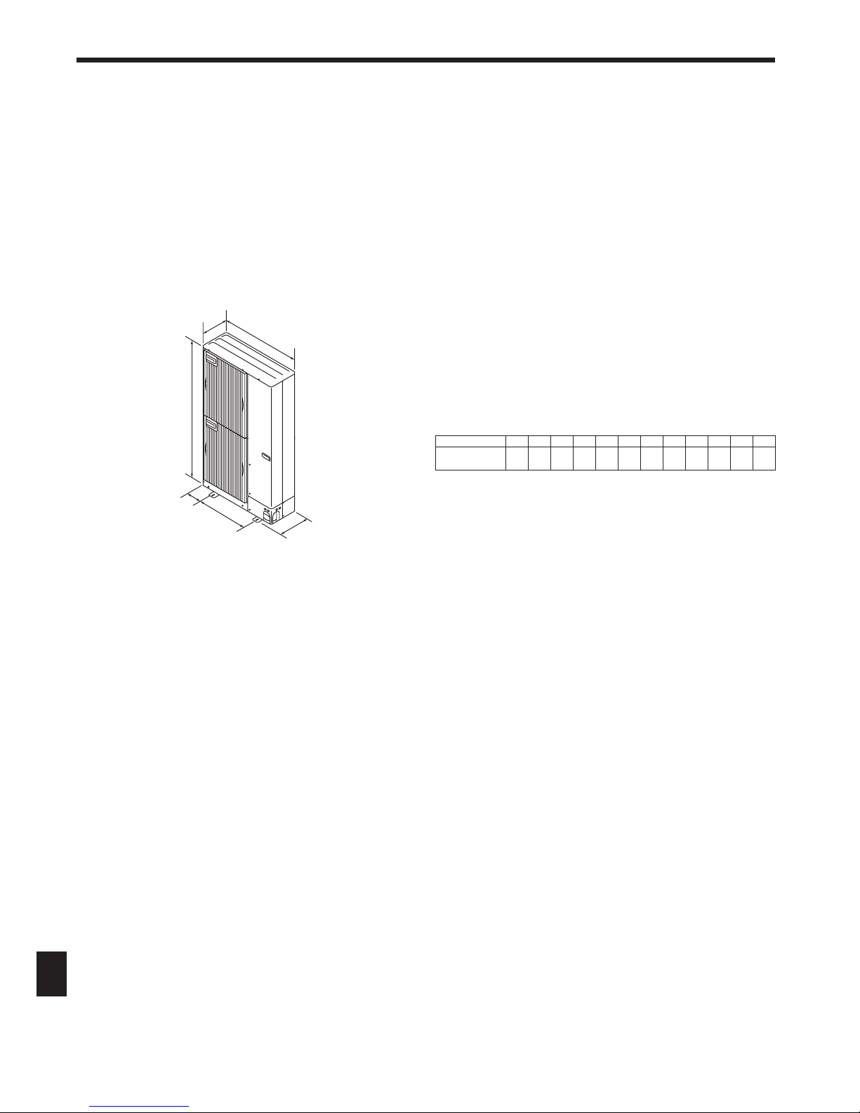
2.3. Outline dimensions (Outdoor unit) (Fig. 2-1)
Constraints on indoor unit installation
You should note that indoor units that can be connected to this outdoor unit are the
following models.
• Indoor units with model numbers 15-140 can be connected. Refer to the table 1
below for possible room, indoor unit combinations.
Verifi cation
The rated capacity should be determined by observing the table below. The unit’s
quantities are limited in 1 to 8 units. For the next step, make sure that the total rated
capacity selected will stay in a range of 50% - 130% of the outdoor unit capacity.
• PUMY-P125 7.1 - 18.2 kW
• PUMY-P140 8.0 - 20.2 kW
Indoor unit type
15 20 25 32 40 50 63 71 80 100 125 140
Rated capacity
(Cooling) (kW)
1.7 2.2 2.8 3.6 4.5 5.6 7.1 8.0 9.0 11.2 14.0 16.0
Combinations in which the total capacity of indoor units exceeds the capacity of the
outdoor unit will reduce the cooling capacity of each indoor unit below their rated
cooling capacity. Thus, combine indoor units with an outdoor unit within the outdoor
unit’s capacity, if possible.
Fig. 2-1
(mm)
950
330+30
1350
175
600
370
5
2. Installation location
Fig. 2-3
Fig. 2-7
Fig. 2-8
Fig. 2-9
Fig. 2-10 Fig. 2-11
Fig. 2-12 Fig. 2-13 Fig. 2-14
Fig. 2-6
Fig. 2-5Fig. 2-4Fig. 2-2
150
200
300
200
1000
150
1000
300
1500
1500
500
1000
600
2000
150
1500
600
3000
500
1500
800
150
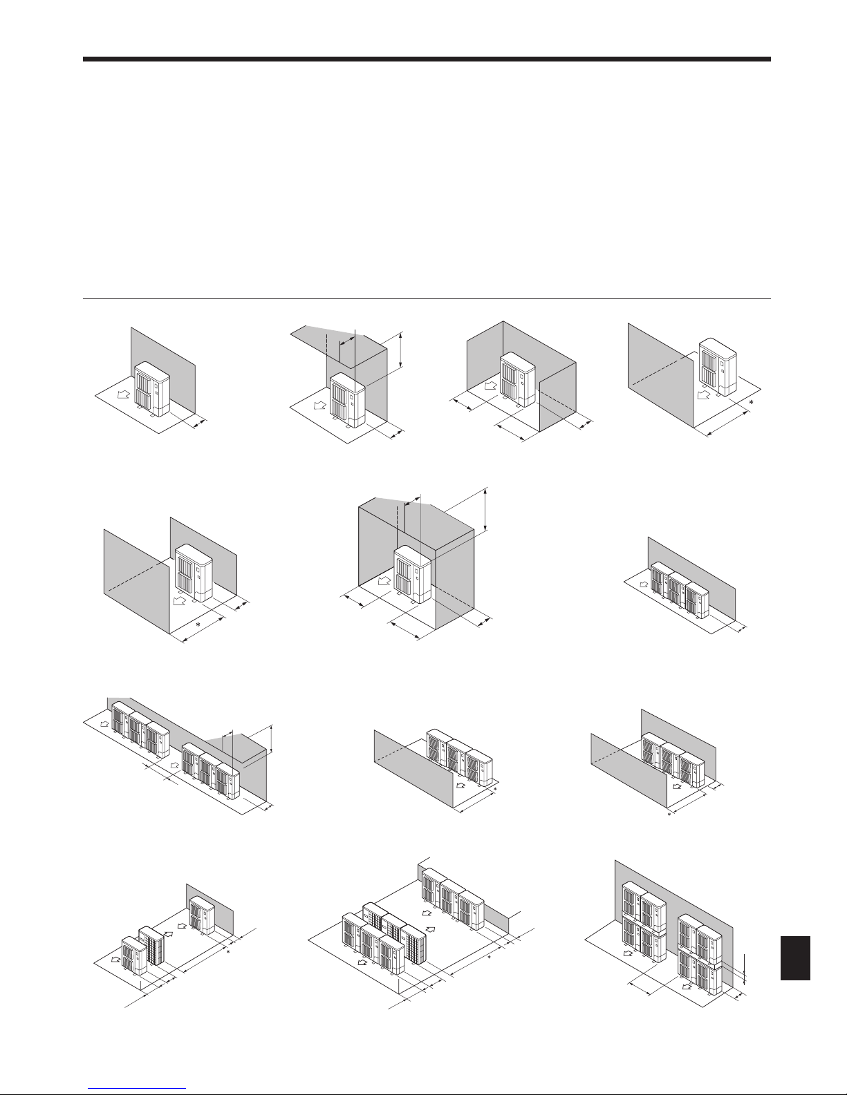
2.4. Ventilation and service space
2.4.1. When installing a single outdoor unit
Minimum dimensions are as follows, except for Max., meaning Maximum dimensions, indicated.
Refer to the fi gures for each case.
1 Obstacles at rear only (Fig. 2-2)
2 Obstacles at rear and above only (Fig. 2-3)
• Do not install the optional air outlet guides for upward airfl ow.
3 Obstacles at rear and sides only (Fig. 2-4)
4 Obstacles at front only (Fig. 2-5)
∗ When using an optional air outlet guide, the clearance is 500 mm or more.
5 Obstacles at front and rear only (Fig. 2-6)
∗ When using an optional air outlet guide, the clearance is 500 mm or more.
6 Obstacles at rear, sides, and above only (Fig. 2-7)
• Do not install the optional air outlet guides for upward airfl ow.
2.4.2. When installing multiple outdoor units
Leave 10 mm space or more between the units.
1 Obstacles at rear only (Fig. 2-8)
2 Obstacles at rear and above only (Fig. 2-9)
• No more than three units must be installed side by side. In addition, leave space as shown.
• Do not install the optional air outlet guides for upward airfl ow.
3 Obstacles at front only (Fig. 2-10)
∗ When using an optional air outlet guide, the clearance is 1000 mm or more.
4 Obstacles at front and rear only (Fig. 2-11)
∗ When using an optional air outlet guide, the clearance is 1000 mm or more.
5 Single parallel unit arrangement (Fig. 2-12)
∗ When using an optional air outlet guide installed for upward airfl ow, the clearance is 1000
mm or more.
6 Multiple parallel unit arrangement (Fig. 2-13)
∗ When using an optional air outlet guide installed for upward airfl ow, the clearance is 1500
mm or more.
7 Stacked unit arrangement (Fig. 2-14)
• The units can be stacked up to two units high.
• No more than two stacked units must be installed side by side. In addition, leave space as shown.
Max.500
500
1000
Max.500
250
250
300
1500
Max.300
1500
500
1500
 Loading...