


SAFETY PRECAUTIONS
WARNING
CAUTION
Indicates that incorrect handling may cause hazardous conditions,
resulting in death or severe injury.
Indicates that incorrect handling may cause hazardous conditions,
resulting in minor or moderate injury or property damage.
(Read these precautions before using this product.)
Before using this product, please read this manual and the relevant manuals carefully and pay full attention
to safety to handle the product correctly.
In this manual, the safety precautions are classified into two levels: " WARNING" and " CAUTION".
Under some circumstances, failure to observe the precautions given under " CAUTION" may lead to
serious consequences.
Observe the precautions of both levels because they are important for personal and system safety.
Make sure that the end users read this manual and then keep the manual in a safe place for future
reference.
A - 1
[Design Precautions]
Q series model
AnS/A series model
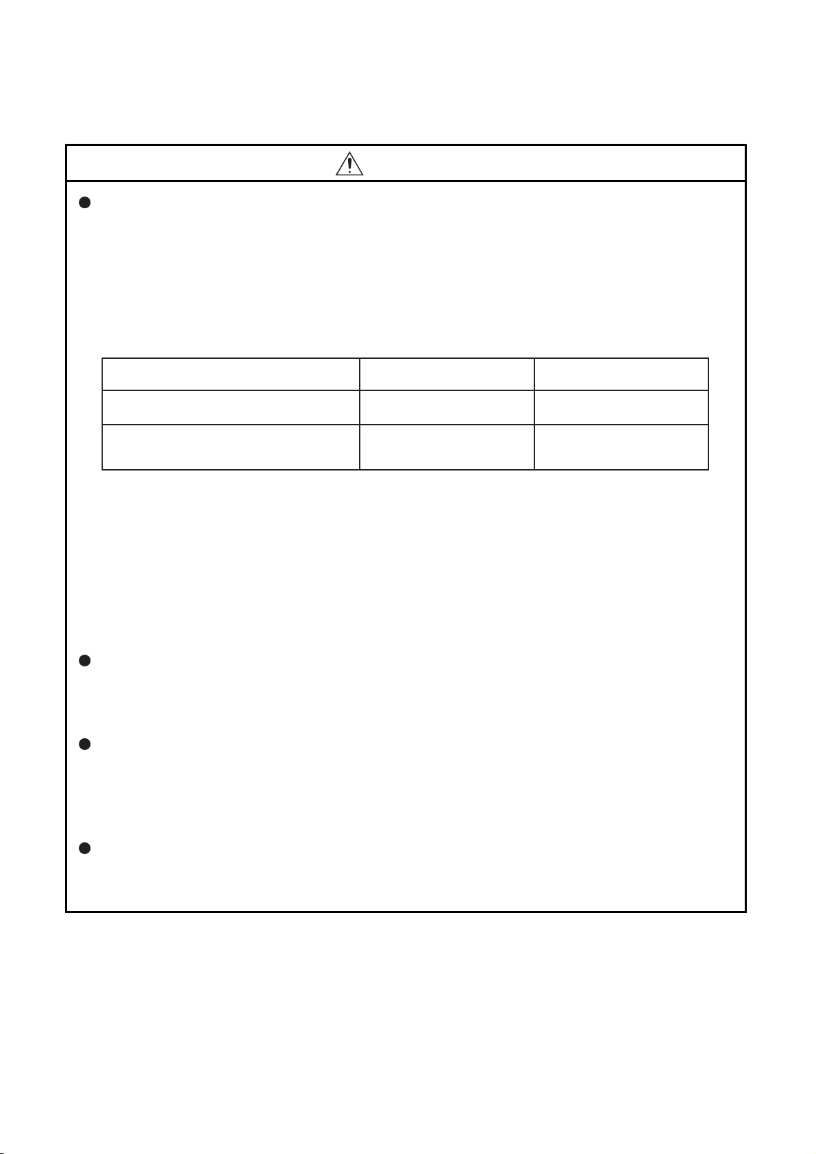
All outputs are turned off.
All outputs are turned off.
All outputs are held or turned
off according to the parameter
setting.
Overcurrent or overvoltage protection of the
power supply module is activated.
The CPU module detects an error such as a
watchdog timer error by the self-diagnostic
function.
All outputs are turned off.
Status
WARNING
Configure safety circuits external to the programmable controller to ensure that the entire system
operates safely even when a fault occurs in the external power supply or the programmable
controller. Failure to do so may result in an accident due to an incorrect output or malfunction.
(1) Configure external safety circuits, such as an emergency stop circuit, protection circuit, and
protective interlock circuit for forward/reverse operation or upper/lower limit positioning.
(2) The programmable controller stops its operation upon detection of the following status, and the
output status of the system will be as shown below.
All outputs may turn on when an error occurs in the part, such as I/O control part, where the CPU
module cannot detect any error. To ensure safety operation in such a case, provide a safety
mechanism or a fail-safe circuit external to the programmable controller. For a fail-safe circuit
example, refer to Appendix 8 General Safety Requirements in the QCPU User's Manual
(Hardware Design, Maintenance and Inspection).
(3) Outputs may remain on or off due to a failure of an output module relay or transistor. Configure
an external circuit for monitoring output signals that could cause a serious accident.
In an output module, when a load current exceeding the rated current or an overcurrent caused by a
load short-circuit flows for a long time, it may cause smoke and fire. To prevent this, configure an
external safety circuit, such as a fuse.
Configure a circuit so that the programmable controller is turned on first and then the external power
supply.
If the external power supply is turned on first, an accident may occur due to an incorrect output or
malfunction.
For the operating status of each station after a communication failure, refer to relevant manuals for
the network.
Incorrect output or malfunction due to a communication failure may result in an accident.
A - 2
[Design Precautions]
WARNING
When changing data of the running programmable controller from a peripheral connected to the
CPU module or from a personal computer connected to an intelligent function module, configure an
interlock circuit in the sequence program to ensure that the entire system will always operate safely.
For program modification and operating status change, read relevant manuals carefully and ensure
the safety before operation.
Especially, in the case of a control from an external device to a remote programmable controller,
immediate action cannot be taken for a problem on the programmable controller due to a
communication failure.
To prevent this, configure an interlock circuit in the sequence program, and determine corrective
actions to be taken between the external device and CPU module in case of a communication
failure.
[Design Precautions]
CAUTION
Do not install the control lines or communication cables together with the main circuit lines or power
cables.
Keep a distance of 100mm (3.94 inches) or more between them.
Failure to do so may result in malfunction due to noise.
When a device such as a lamp, heater, or solenoid valve is controlled through an output module, a
large current (approximately ten times greater than normal) may flow when the output is turned from
off to on.
Take measures such as replacing the module with one having a sufficient current rating.
After the CPU module is powered on or is reset, the time taken to enter the RUN status varies
depending on the system configuration, parameter settings, and/or program size.
Design circuits so that the entire system will always operate safely, regardless of the time.
A - 3

[Installation Precautions]
CAUTION
Use the programmable controller in an environment that meets the general specifications in the
QCPU User's Manual (Hardware Design, Maintenance and Inspection).
Failure to do so may result in electric shock, fire, malfunction, or damage to or deterioration of the
product.
To mount the module, while pressing the module mounting lever located in the lower part of the
module, fully insert the module fixing projection(s) into the hole(s) in the base unit and press the
module until it snaps into place.
Incorrect mounting may cause malfunction, failure or drop of the module.
When using the programmable controller in an environment of frequent vibrations, fix the module
with a screw.
Tighten the screw within the specified torque range.
Undertightening can cause drop of the screw, short circuit or malfunction.
Overtightening can damage the screw and/or module, resulting in drop, short circuit, or malfunction.
When using an extension cable, connect it to the extension cable connector of the base unit
securely.
Check the connection for looseness.
Poor contact may cause incorrect input or output.
When using a memory card, fully insert it into the memory card slot.
Check that it is inserted completely.
Poor contact may cause malfunction.
Shut off the external power supply for the system in all phases before mounting or removing the
module. Failure to do so may result in damage to the product.
A module can be replaced online (while power is on) on any MELSECNET/H remote I/O station or in
the system where a CPU module supporting the online module change function is used.
Note that there are restrictions on the modules that can be replaced online, and each module has its
predetermined replacement procedure.
For details, refer to the relevant sections in the QCPU User's Manual (Hardware Design,
Maintenance and Inspection) and in the manual for the corresponding module.
Do not directly touch any conductive parts and electronic components of the module.
Doing so can cause malfunction or failure of the module.
When using a Motion CPU module and modules designed for motion control, check that the
combinations of these modules are correct before applying power.
The modules may be damaged if the combination is incorrect.
For details, refer to the user's manual for the Motion CPU module.
A - 4
[Wiring Precautions]
WARNING
Shut off the external power supply (all phases) used in the system before installation and wiring.
Failure to do so may result in electric shock or damage to the product.
After wiring, attach the included terminal cover to the module before turning it on for operation.
Failure to do so may result in electric shock.
[Wiring Precautions]
CAUTION
Ground the FG and LG terminals to the protective ground conductor dedicated to the programmable
controller.
Failure to do so may result in electric shock or malfunction.
Use applicable solderless terminals and tighten them within the specified torque range. If any spade
solderless terminal is used, it may be disconnected when the terminal screw comes loose, resulting
in failure.
Check the rated voltage and terminal layout before wiring to the module, and connect the cables
correctly.
Connecting a power supply with a different voltage rating or incorrect wiring may cause a fire or
failure.
Connectors for external connection must be crimped or pressed with the tool specified by the
manufacturer, or must be correctly soldered.
Incomplete connections could result in short circuit, fire, or malfunction.
Do not install the control lines or communication cables together with the main circuit lines or power
cables.
Failure to do so may result in malfunction due to noise.
Tighten the terminal screw within the specified torque range.
Undertightening can cause short circuit, fire, or malfunction.
Overtightening can damage the screw and/or module, resulting in drop, short circuit, or malfunction.
Prevent foreign matter such as dust or wire chips from entering the module.
Such foreign matter can cause a fire, failure, or malfunction.
A - 5
[Wiring Precautions]
CAUTION
A protective film is attached to the top of the module to prevent foreign matter, such as wire chips,
from entering the module during wiring.
Do not remove the film during wiring.
Remove it for heat dissipation before system operation.
Mitsubishi programmable controllers must be installed in control panels.
Connect the main power supply to the power supply module in the control panel through a relay
terminal block.
Wiring and replacement of a power supply module must be performed by maintenance personnel
who is familiar with protection against electric shock. (For wiring methods, refer to the QCPU User's
Manual (Hardware Design, Maintenance and Inspection)).
[Startup and Maintenance Precautions]
WARNING
Do not touch any terminal while power is on.
Doing so will cause electric shock or malfunction.
Correctly connect the battery connector.
Do not charge, disassemble, heat, short-circuit, solder, or throw the battery into the fire.
Doing so will cause the battery to produce heat, explode, or ignite, resulting in injury and fire.
Shut off the external power supply (all phases) used in the system before cleaning the module or
retightening the terminal screws, connector screws, or module fixing screws.
Failure to do so may result in electric shock or cause the module to fail or malfunction.
Undertightening can cause drop of the screw, short circuit or malfunction.
Overtightening can damage the screw and/or module, resulting in drop, short circuit, or malfunction.
A - 6

[Startup and Maintenance Precautions]
CAUTION
Before performing online operations (especially, program modification, forced output, and operation
status change) for the running CPU module from the peripheral connected, read relevant manuals
carefully and ensure the safety.
Improper operation may damage machines or cause accidents.
Do not disassemble or modify the modules.
Doing so may cause failure, malfunction, injury, or a fire.
Use any radio communication device such as a cellular phone or PHS (Personal Handy-phone
System) more than 25cm (9.85 inches) away in all directions from the programmable controller.
Failure to do so may cause malfunction.
Shut off the external power supply for the system in all phases before mounting or removing the
module. Failure to do so may cause the module to fail or malfunction.
A module can be replaced online (while power is on) on any MELSECNET/H remote I/O station or in
the system where a CPU module supporting the online module change function is used.
Note that there are restrictions on the modules that can be replaced online, and each module has its
predetermined replacement procedure.
For details, refer to the relevant sections in the QCPU User's Manual (Hardware Design,
Maintenance and Inspection) and in the manual for the corresponding module.
After the first use of the product, do not mount/remove the module to/from the base unit, and the
terminal block to/from the module more than 50 times (IEC 61131-2 compliant) respectively.
Exceeding the limit of 50 times may cause malfunction.
Do not drop or apply shock to the battery to be installed in the module.
Doing so may damage the battery, causing the battery fluid to leak inside the battery.
If the battery is dropped or any shock is applied to it, dispose of it without using.
Before handling the module, touch a grounded metal object to discharge the static electricity from
the human body.
Failure to do so may cause the module to fail or malfunction.
A - 7
[Disposal Precautions]
CAUTION
When disposing of this product, treat it as industrial waste.
When disposing of batteries, separate them from other wastes according to the local regulations.
(For details of the battery directive in EU member states, refer to the QCPU User's Manual
(Hardware Design, Maintenance and Inspection).)
[Transportation Precautions]
CAUTION
When transporting lithium batteries, follow the transportation regulations.
(For details of the regulated models, refer to the QCPU User's Manual (Hardware Design,
Maintenance and Inspection).)
A - 8

CONDITIONS OF USE FOR THE PRODUCT
(1) Mitsubishi programmable controller ("the PRODUCT") shall be used in conditions;
i) where any problem, fault or failure occurring in the PRODUCT, if any, shall not lead to any major
or serious accident; and
ii) where the backup and fail-safe function are systematically or automatically provided outside of
the PRODUCT for the case of any problem, fault or failure occurring in the PRODUCT.
(2) The PRODUCT has been designed and manufactured for the purpose of being used in general
industries.
MITSUBISHI SHALL HAVE NO RESPONSIBILITY OR LIABILITY (INCLUDING, BUT NOT
LIMITED TO ANY AND ALL RESPONSIBILITY OR LIABILITY BASED ON CONTRACT,
WARRANTY, TORT, PRODUCT LIABILITY) FOR ANY INJURY OR DEATH TO PERSONS OR
LOSS OR DAMAGE TO PROPERTY CAUSED BY the PRODUCT THAT ARE OPERATED OR
USED IN APPLICATION NOT INTENDED OR EXCLUDED BY INSTRUCTIONS, PRECAUTIONS,
OR WARNING CONTAINED IN MITSUBISHI'S USER, INSTRUCTION AND/OR SAFETY
MANUALS, TECHNICAL BULLETINS AND GUIDELINES FOR the PRODUCT.
("Prohibited Application")
Prohibited Applications include, but not limited to, the use of the PRODUCT in;
• Nuclear Power Plants and any other power plants operated by Power companies, and/or any
other cases in which the public could be affected if any problem or fault occurs in the PRODUCT.
• Railway companies or Public service purposes, and/or any other cases in which establishment of
a special quality assurance system is required by the Purchaser or End User.
• Aircraft or Aerospace, Medical applications, Train equipment, transport equipment such as
Elevator and Escalator, Incineration and Fuel devices, Vehicles, Manned transportation,
Equipment for Recreation and Amusement, and Safety devices, handling of Nuclear or
Hazardous Materials or Chemicals, Mining and Drilling, and/or other applications where there is a
significant risk of injury to the public or property.
Notwithstanding the above, restrictions Mitsubishi may in its sole discretion, authorize use of the
PRODUCT in one or more of the Prohibited Applications, provided that the usage of the PRODUCT
is limited only for the specific applications agreed to by Mitsubishi and provided further that no
special quality assurance or fail-safe, redundant or other safety features which exceed the general
specifications of the PRODUCTs are required. For details, please contact the Mitsubishi
representative in your region.
A - 9

REVISIONS
*The manual number is given on the bottom left of the back cover.
Print date Manual number Revision
Dec., 2008 SH(NA)-080808ENG-A
Mar., 2009 SH(NA)-080808ENG-B Partial correction
Nov., 2009 SH(NA)-080808ENG-C Partial correction
May, 2010 SH(NA)-080808ENG-D Partial correction
May, 2011 SH(NA)-080808ENG-E Partial correction
Sep., 2011 SH(NA)-080808ENG-F Partial correction
Oct., 2011 SH(NA)-080808ENG-G Partial correction
May, 2012 SH(NA)-080808ENG-H Partial correction
Jan., 2014 SH(NA)-080808ENG-I Partial correction
Jul. 2014 SH(NA)-080808ENG-J Partial correction
First edition
SAFETY PRECAUTIONS, INTRODUCTION, MANUALS, MANUAL PAGE
ORGANIZATION, Section 1.3, 1.6, 2.2.2, 2.2.3, 2.3, 2.3.4, 2.3.5, 3.3, 3.7,
3.8.1, 3.8.2, 4.1.1, 4.1.2, 4.2.2, 4.2.3, 5.1.1, 5.2.1, 5.2.5, 5.2.6, 5.2.8, 6.1,
6.3, 6.5, 6.6.1, 6.6.5, 6.11.3, 6.12.2, 6.13.3, 6.14, 6.15.2, 6.20, 6.22.2, 6.22.4,
CHAPTER 7, Section 7.1.2, 7.2, 8.2, 9.1, 9.2, 9.2.11, 9.3.3, 9.5.2, 9.7.4, 9.10,
10.1.1, 10.1.2, Appendix 1, Appendix 3
SAFETY PRECAUTIONS, Section 4.2.2, 9.2.10, 9.7.4
Addition
CONDITIONS OF USE FOR THE PRODUCT
SAFETY PRECAUTIONS, MANUALS, Section 1.5.1, 1.5.2, 2.1, 2.2.1, 2.2.3,
2.4, 3.7, 4.2.2, 5.1.1, 5.1.4, 5.2.9, 6.2, 6.5, 6.6.2, 6.6.3, 6.6.4, 6.11.2, 6.12.2,
6.13.1, 6.14, 6.17.1, 6.22, 6.24, 7.1.3, 8.1.1, 9.2.9, 9.2.10, 9.3.1, 9.5.1, 9.7,
9.8, 9.9, 9.10.1, 9.11.1, 9.11.2, 9.12.3, 9.13.2, 10.1.2, Appendix 2.1, Appendix 2.2, Appendix 2.3, Appendix 2.4
SAFETY PRECAUTIONS, GENERIC TERMS AND ABBREVIATIONS,
Section 3.1, 3.4, 3.6, 3.8.1, 3.8.2, 5.1.1, 5.1.2, 5.1.5, 5.2.1, 5.2.8, 5.2.9, 6.5,
6.25, 7.2, CHAPTER 8, Section 9.2, 9.2.4, 9.2.10, 9.3.2, 9.3.3, 9.10, 10.1.3
Deletion
CHAPTER 12
SAFETY PRECAUTIONS, INTRODUCTION, MANUAL PAGE ORGANIZATION, Section 2.4.5, 5.2.6, 6.24, 9.2, 9.2.10, 9.12.4
GENERIC TERMS AND ABBREVIATIONS, Section 1.5.2, 3.8, 4.2.2, 6.22.2,
6.22.4, 10.1.2
Section 5.2.8, 6.2, 6.12.3, 8.1.1, 8.1.2, 9.1, 9.2.13, 9.3.2, 9.3.3, 9.7, 9.7.4,
Appendix 1
GENERIC TERMS AND ABBREVIATIONS, Section 4.2.1, 5.2.1, 5.2.5,
5.2.10, 6.12.3, 9.1, 9.7.2, 9.7.6, 10.1.3, Appendix 2.2, 2.3
GENERIC TERMS AND ABBREVIATIONS, Section 1.5.2, 3.8, 4.2.2, 6.22.2,
6.22.4, 10.1.2
Japanese manual version SH-080803-K
This manual confers no industrial property rights or any rights of any other kind, nor does it confer any patent licenses. Mitsubishi Electric Corporation cannot be held responsible for any problems involving industrial property rights which may occur
as a result of using the contents noted in this manual.
© 2008 MITSUBISHI ELECTRIC CORPORATION
A - 10
INTRODUCTION
Remark
This manual describes the memory maps, functions, programs, I/O number assignment, and devices of the Q series CPU
module.
Before using this product, please read this manual and the relevant manuals carefully and develop familiarity with the
functions and performance of the Q series programmable controller to handle the product correctly.
When applying the program examples introduced in this manual to the actual system, ensure the applicability and confirm that
it will not cause system control problems.
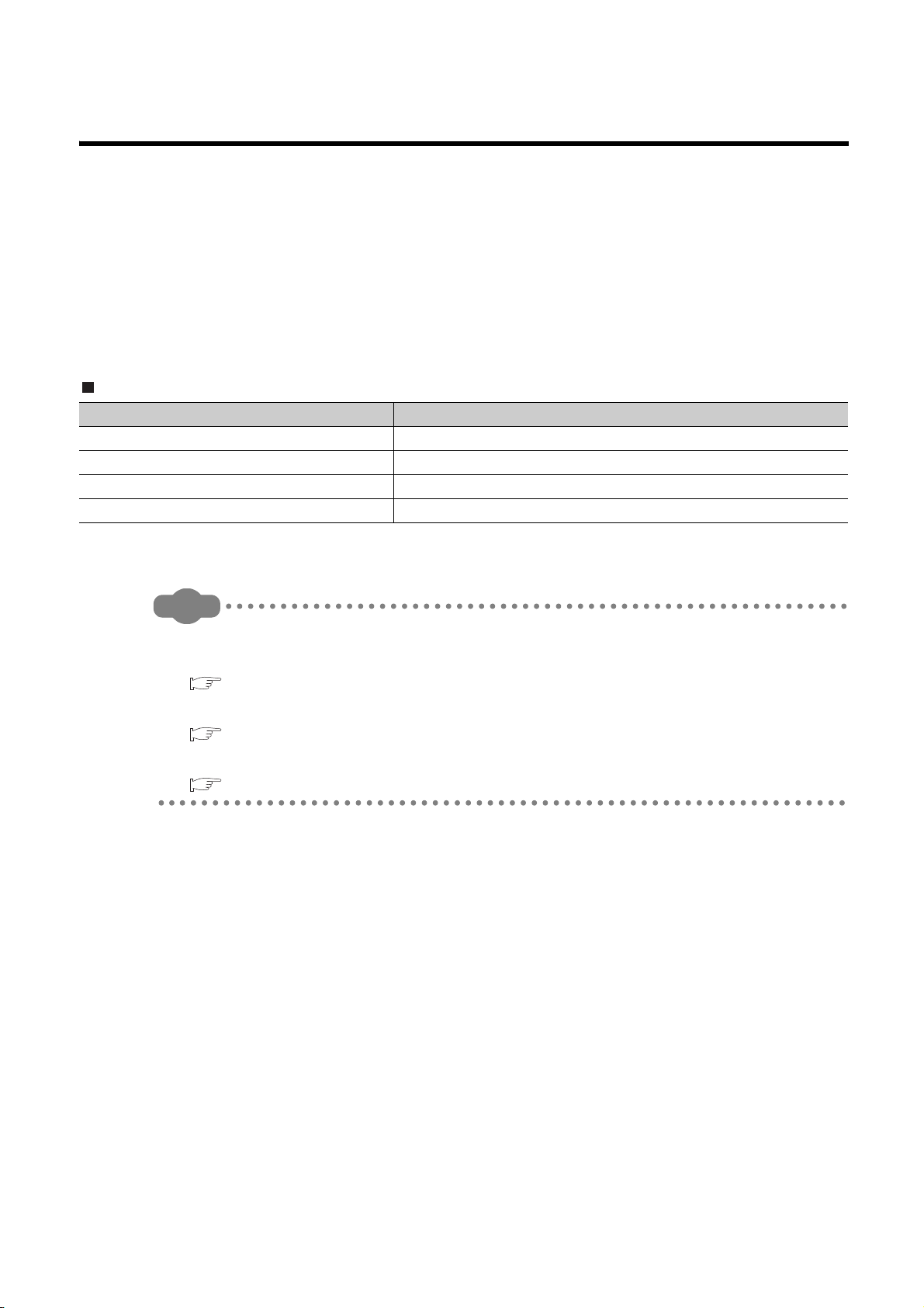
Relevant CPU module
CPU module Model
Basic model QCPU Q00JCPU, Q00CPU, Q01CPU
High Performance model QCPU Q02CPU, Q02HCPU, Q06HCPU, Q12HCPU, Q25HCPU
Process CPU Q02PHCPU, Q06PHCPU, Q12PHCPU, Q25PHCPU
Redundant CPU Q12PRHCPU, Q25PRHCPU
This manual does not describe the specifications of the power supply modules, base units, extension cables, memory
cards, and batteries.
For details, refer to the following.
QCPU User's Manual (Hardware Design, Maintenance and Inspection)
For multiple CPU systems, refer to the following.
QCPU User's Manual (Multiple CPU System)
For redundant systems, refer to the following.
QnPRHCPU User's Manual (Redundant System)
A - 11

CONTENTS
CONTENTS
SAFETY PRECAUTIONS......................................................................................................................A - 1
CONDITIONS OF USE FOR THE PRODUCT ...................................................................................... A - 9
REVISIONS ...........................................................................................................................................A - 10
INTRODUCTION ...................................................................................................................................A - 11
MANUALS ............................................................................................................................................. A - 18
MANUAL PAGE ORGANIZATION......................................................................................................... A - 20
GENERIC TERMS AND ABBREVIATIONS ..........................................................................................A - 22
CHAPTER1 OVERVIEW 1-1 to 1-20
1.1 Processing Order in the CPU Module....................................................................................1 - 1
1.2 Storing and Executing Programs ........................................................................................... 1 - 2
1.3 Structured Programming ........................................................................................................ 1 - 3
1.4 Devices and Instructions Useful for Programming................................................................. 1 - 6
1.5 Features................................................................................................................................. 1 - 11
1.5.1 Features of the Basic model QCPU ..................................................................................1 - 11
1.5.2 Features of the High Performance model QCPU..............................................................1 - 13
1.5.3 Features of the Process CPU ...........................................................................................1 - 15
1.5.4 Features of the Redundant CPU.......................................................................................1 - 17
1.6 Checking Serial Number and Function Version ..................................................................... 1 - 19
CHAPTER2 SEQUENCE PROGRAMS 2-1 to 2-51
2.1 Sequence Program Overview ................................................................................................ 2 - 1
2.2 Sequence Program Configuration.......................................................................................... 2 - 3
2.2.1 Main routine program ........................................................................................................2 - 4
2.2.2 Subroutine program ..........................................................................................................2 - 5
2.2.3 Interrupt program ..............................................................................................................2 - 6
2.3 Settings When Program is Divided .......................................................................................2 - 14
2.3.1 Initial execution type program ...........................................................................................2 - 19
2.3.2 Scan execution type program ...........................................................................................2 - 22
2.3.3 Low-speed execution type program ..................................................................................2 - 23
2.3.4 Stand-by type program ......................................................................................................2 - 31
2.3.5 Fixed scan execution type program ..................................................................................2 - 36
2.3.6 Changing the program execution type ..............................................................................2 - 40
2.4 Data Used in Sequence Programs ........................................................................................2 - 42
2.4.1 BIN (Binary Code) ............................................................................................................. 2 - 45
2.4.2 HEX (Hexadecimal)...........................................................................................................2 - 46
2.4.3 BCD (Binary-coded Decimal) ............................................................................................2 - 47
2.4.4 Real number (Floating-point data).....................................................................................2 - 48
2.4.5 Character string data.........................................................................................................2 - 51
CHAPTER3 CPU MODULE OPERATION 3-1 to 3-16
3.1 Initial Processing .................................................................................................................... 3 - 1
3.2 I/O Refresh (Refresh Processing with Input/Output Modules) ............................................... 3 - 2
A - 12

3.3 Program Operation ................................................................................................................ 3 - 2
3.4 END Processing..................................................................................................................... 3 - 3
3.5 Operation Processing in the RUN, STOP, or PAUSE Status ................................................. 3 - 4
3.6 Operation Processing during Momentary Power Failure ....................................................... 3 - 6
3.7 Data Clear Processing ........................................................................................................... 3 - 7
3.8 I/O Processing and Response Delay.....................................................................................3 - 9
3.8.1 Refresh mode....................................................................................................................3 - 10
3.8.2 Direct mode.......................................................................................................................3 - 14
CHAPTER4 ASSIGNMENT OF BASE UNIT AND I/O NUMBER 4-1 to 4-17
4.1 Base Unit Assignment............................................................................................................ 4 - 1
4.1.1 Base mode........................................................................................................................4 - 1
4.1.2 Base unit assignment setting ............................................................................................4 - 2
4.2 I/O Number Assignment......................................................................................................... 4 - 4
4.2.1 Concept of I/O number assignment ..................................................................................4 - 5
4.2.2 Setting I/O numbers ..........................................................................................................4 - 8
4.2.3 I/O number setting example ..............................................................................................4 - 14
4.2.4 Checking I/O numbers ......................................................................................................4 - 17
CHAPTER5 MEMORIES AND FILES USED FOR CPU MODULE 5-1 to 5-51
5.1 Memories Used for Basic Model QCPU................................................................................. 5 - 1
5.1.1 Memory composition and storable data ............................................................................5 - 1
5.1.2 Program memory ..............................................................................................................5 - 3
5.1.3 Standard ROM ..................................................................................................................5 - 6
5.1.4 Standard RAM ...................................................................................................................5 - 7
5.1.5 Operating and writing programs in the standard ROM (boot operation) ...........................5 - 9
5.2 Memories Used for High Performance model QCPU, Process CPU, and Redundant CPU..5 - 13
5.2.1 Memory composition and storable data ............................................................................5 - 13
5.2.2 Program memory ..............................................................................................................5 - 16
5.2.3 Standard ROM ..................................................................................................................5 - 19
5.2.4 Standard RAM ...................................................................................................................5 - 20
5.2.5 Memory card .....................................................................................................................5 - 22
5.2.6 Writing to the standard ROM and Flash card by GX Developer........................................5 - 26
5.2.7 Automatic all data write from memory card to standard ROM...........................................5 - 31
5.2.8 Operating the program in the standard ROM and memory card (boot operation).............5 - 34
5.2.9 Details of written files ........................................................................................................5 - 39
5.2.10 Specifying valid parameters (parameter-valid drive setting)..............................................5 - 40
5.3 Program File Structure ........................................................................................................... 5 - 41
5.4 File Operations by GX Developer and Handling Precautions................................................5 - 43
5.4.1 File operations...................................................................................................................5 - 43
5.4.2 Precautions for handling files ............................................................................................ 5 - 44
5.4.3 File size.............................................................................................................................5 - 45
5.4.4 Units of file sizes ...............................................................................................................5 - 48
A - 13

CHAPTER6 FUNCTIONS 6-1 to 6-151
6.1 Function List........................................................................................................................... 6 - 1
6.2 Constant Scan ....................................................................................................................... 6 - 4
6.3 Latch Function ....................................................................................................................... 6 - 8
6.4 Output Mode at Operating Status Change (STOP to RUN)...................................................6 - 11
6.5 Clock Function ....................................................................................................................... 6 - 14
6.6 Remote Operation.................................................................................................................. 6 - 19
6.6.1 Remote RUN/STOP .......................................................................................................... 6 - 19
6.6.2 Remote PAUSE ................................................................................................................. 6 - 22
6.6.3 Remote RESET.................................................................................................................6 - 25
6.6.4 Remote latch clear ............................................................................................................6 - 29
6.6.5 Relationship between remote operation and RUN/STOP status of the CPU module ....... 6 - 31
6.7 Q Series-compatible Module Input Response Time Selection (I/O Response Time) ............ 6 - 32
6.8 Error Time Output Mode Setting............................................................................................6 - 34
6.9 H/W Error Time PLC Operation Mode Setting ....................................................................... 6 - 35
6.10 Intelligent Function Module Switch Setting ............................................................................ 6 - 36
6.11 Monitor Function .................................................................................................................... 6 - 38
6.11.1 Monitor condition setting ...................................................................................................6 - 39
6.11.2 Local device monitor/test ..................................................................................................6 - 45
6.11.3 External input/output forced on/off ...................................................................................6 - 48
6.12 Writing Programs While CPU Module is in RUN Status......................................................... 6 - 54
6.12.1 Online change (ladder mode)............................................................................................ 6 - 54
6.12.2 Online change (files) ........................................................................................................6 - 58
6.12.3 Precautions for online change........................................................................................... 6 - 60
6.13 Execution Time Measurement ............................................................................................... 6 - 65
6.13.1 Program monitor list ..........................................................................................................6 - 65
6.13.2 Interrupt program monitor list ............................................................................................6 - 69
6.13.3 Scan time measurement ..................................................................................................6 - 70
6.14 Sampling Trace Function ....................................................................................................... 6 - 74
6.15 Debug Function from Multiple GX Developers....................................................................... 6 - 87
6.15.1 Simultaneous monitoring from multiple GX Developers function ......................................6 - 87
6.15.2 Online change function from multiple GX Developers .....................................................6 - 89
6.16 Watchdog Timer (WDT) ......................................................................................................... 6 - 91
6.17 Self-diagnostic Function......................................................................................................... 6 - 93
6.17.1 Interrupt caused by an error..............................................................................................6 - 102
6.17.2 LEDs indicating errors.......................................................................................................6 - 103
6.17.3 Error clear .........................................................................................................................6 - 104
6.18 Error History ........................................................................................................................... 6 - 105
6.18.1 Basic model QCPU ...........................................................................................................6 - 105
6.18.2 High Performance model QCPU, Process CPU, and Redundant CPU ............................6 - 106
6.19 System Protection.................................................................................................................. 6 - 107
6.19.1 Password registration........................................................................................................ 6 - 108
6.19.2 Remote password ............................................................................................................6 - 110
6.20 System Display of CPU Module with GX Developer.............................................................. 6 - 115
6.21 LED Display ........................................................................................................................... 6 - 120
A - 14

6.21.1 Methods for turning off the LEDs.......................................................................................6 - 121
6.21.2 LED indication priority .......................................................................................................6 - 122
6.22 High Speed Interrupt Function ............................................................................................... 6 - 125
6.22.1 High speed interrupt program execution function .............................................................6 - 126
6.22.2 High speed I/O refresh and high speed buffer transfer functions...................................... 6 - 127
6.22.3 Processing time.................................................................................................................6 - 129
6.22.4 Restrictions .......................................................................................................................6 - 131
6.23 Interrupt from Intelligent Function Module .............................................................................6 - 134
6.24 Serial Communication Function ............................................................................................. 6 - 135
6.25 Service Processing ................................................................................................................ 6 - 143
6.25.1 Module service interval time read .....................................................................................6 - 143
6.26 Initial Device Value................................................................................................................. 6 - 144
6.27 Memory Check Function ........................................................................................................ 6 - 149
CHAPTER7 COMMUNICATIONS WITH INTELLIGENT FUNCTION MODULE
7.1 Communications between CPU Module and Intelligent Function Module ............................. 7 - 1
7.1.1 Initial setting and auto refresh setting by GX Configurator................................................7 - 2
7.1.2 Initial setting by initial device value ...................................................................................7 - 5
7.1.3 Communications with the FROM and TO instructions ......................................................7 - 5
7.1.4 Communications using the intelligent function module device..........................................7 - 6
7.1.5 Communications using the intelligent function module dedicated instruction ...................7 - 8
7.2 Access to the AnS/A Series Special Function Modules ......................................................... 7 - 10
7-1 to 7-10
CHAPTER8 PARAMETERS 8-1 to 8-34
8.1 PLC Parameters .................................................................................................................... 8 - 2
8.1.1 Basic model QCPU ...........................................................................................................8 - 2
8.1.2 High Performance model QCPU, Process CPU, and Redundant CPU ............................8 - 14
8.2 Redundant Parameters ......................................................................................................... 8 - 27
8.3 Network Parameters .............................................................................................................. 8 - 29
8.4 Remote Password.................................................................................................................. 8 - 34
CHAPTER9 DEVICES 9-1 to 9-109
9.1 Device List ............................................................................................................................. 9 - 1
9.2 Internal User Devices............................................................................................................. 9 - 5
9.2.1 Input (X) ............................................................................................................................9 - 8
9.2.2 Output (Y)..........................................................................................................................9 - 10
9.2.3 Internal relay (M)...............................................................................................................9 - 11
9.2.4 Latch relay (L) ...................................................................................................................9 - 12
9.2.5 Annunciator (F) .................................................................................................................9 - 14
9.2.6 Edge relay (V) ...................................................................................................................9 - 20
9.2.7 Link relay (B).....................................................................................................................9 - 21
A - 15

9.2.8 Link special relay (SB) ......................................................................................................9 - 23
9.2.9 Step relay (S) ....................................................................................................................9 - 24
9.2.10 Timer (T)............................................................................................................................9 - 25
9.2.11 Counter (C) .......................................................................................................................9 - 34
9.2.12 Data register (D)................................................................................................................ 9 - 40
9.2.13 Link register (W)................................................................................................................9 - 41
9.2.14 Link special register (SW) .................................................................................................9 - 43
9.3 Internal System Devices ........................................................................................................ 9 - 44
9.3.1 Function devices (FX, FY, FD) ..........................................................................................9 - 44
9.3.2 Special relay (SM).............................................................................................................9 - 47
9.3.3 Special register (SD).........................................................................................................9 - 48
9.4 Link Direct Device .................................................................................................................. 9 - 49
9.5 Module Access Devices ......................................................................................................... 9 - 53
9.5.1 Intelligent function module device .....................................................................................9 - 53
9.5.2 Cyclic transmission area device........................................................................................9 - 56
9.6 Index Register (Z) .................................................................................................................. 9 - 57
9.6.1 Index register (Z)...............................................................................................................9 - 57
9.6.2 Switching between the scan execution type and low-speed execution type programs..... 9 - 59
9.6.3 Switching from the scan execution type/low-speed execution type program to the
interrupt/fixed scan execution type program
.......................................................... 9 - 60
9.7 File Register (R)..................................................................................................................... 9 - 64
9.7.1 File register data storage location ..................................................................................... 9 - 65
9.7.2 File register size ................................................................................................................9 - 65
9.7.3 Differences in available accesses by storage memory .....................................................9 - 66
9.7.4 Registration procedure for the file register ........................................................................ 9 - 67
9.7.5 Specification methods of the file register...........................................................................9 - 73
9.7.6 Precautions for using the file register................................................................................9 - 74
9.8 Nesting (N)............................................................................................................................. 9 - 77
9.9 Pointer (P).............................................................................................................................. 9 - 78
9.9.1 Local pointer.....................................................................................................................9 - 79
9.9.2 Common pointer................................................................................................................9 - 81
9.10 Interrupt Pointer (I)................................................................................................................. 9 - 84
9.10.1 List of interrupt pointer numbers and interrupt factors ......................................................9 - 86
9.11 Other Devices ........................................................................................................................ 9 - 93
9.11.1 SFC block device (BL) ......................................................................................................9 - 93
9.11.2 SFC transition device (TR)................................................................................................9 - 93
9.11.3 Network No. specification device (J) .................................................................................9 - 93
9.11.4 I/O No. specification device (U)......................................................................................... 9 - 94
9.11.5 Macro instruction argument device (VD)...........................................................................9 - 95
9.12 Constants ............................................................................................................................... 9 - 96
9.12.1 Decimal constant (K).........................................................................................................9 - 96
9.12.2 Hexadecimal constant (H).................................................................................................9 - 96
9.12.3 Real number (E)................................................................................................................9 - 97
9.12.4 Character string (" ")..........................................................................................................9 - 98
9.13 Convenient Usage of Devices................................................................................................ 9 - 99
9.13.1 Global device ....................................................................................................................9 - 99
9.13.2 Local device ......................................................................................................................9 - 100
A - 16

CHAPTER10 CPU MODULE PROCESSING TIME 10-1 to 10-22
10.1 Scan Time .............................................................................................................................. 10 - 1
10.1.1 Scan time structure ...........................................................................................................10 - 1
10.1.2 Time required for each processing included in scan time .................................................10 - 6
10.1.3 Factors that increase the scan time ..................................................................................10 - 15
10.1.4 Factors that shorten the scan time....................................................................................10 - 20
CHAPTER11 PROCEDURES FOR WRITING PROGRAM TO CPU MODULE
11-1 to 11-15
11.1 Basic Model QCPU................................................................................................................11 - 1
11.1.1 Items to be Considered for Creating Programs................................................................. 11 - 1
11.1.2 Hardware Check ...............................................................................................................11 - 2
11.1.3 Procedure for writing a program........................................................................................11 - 4
11.1.4 Procedure for Boot Operation ...........................................................................................11 - 6
11.2 High Performance Model QCPU, Process CPU, and Redundant CPU .................................11 - 7
11.2.1 Items to be Considered for Creating Programs................................................................. 11 - 7
11.2.2 Hardware Check ...............................................................................................................11 - 8
11.2.3 Procedure for Writing One Program..................................................................................11 - 10
11.2.4 Procedure for Writing Multiple Programs ..........................................................................11 - 12
11.2.5 Procedure for Boot Operation ...........................................................................................11 - 15
APPENDICES APPX-1 to APPX-13
Appendix 1 List of Parameter Numbers ......................................................................................... APPX- 1
Appendix 2 Upgrade by Function Addition..................................................................................... APPX- 5
Appendix 2.1 Upgrade of the Basic model QCPU............................................................... APPX- 5
Appendix 2.2 Upgrade of the High Performance model QCPU.............................................. APPX- 8
Appendix 2.3 Upgrade of the Process CPU.......................................................................APPX- 10
Appendix 2.4 Upgrade of the Redundant CPU................................................................... APPX- 11
Appendix 3 Device Point Assignment Sheet.................................................................................. APPX- 12
INDEX INDEX-1 to INDEX-4
A - 17
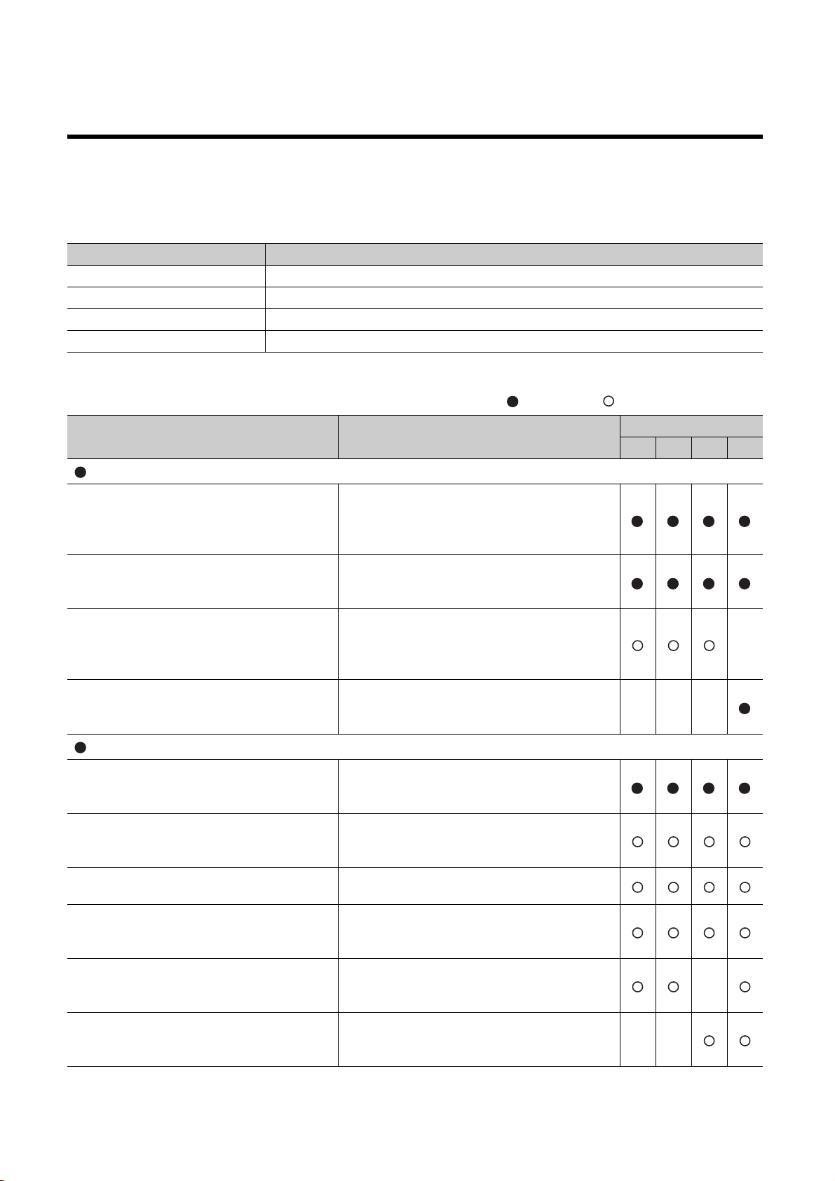
MANUALS
To understand the main specifications, functions, and usage of the CPU module, refer to the basic manuals.
Read other manuals as well when using a different type of CPU module and its functions.
Order each manual as needed, referring to the following list.
Number (in the list below) CPU module
1) Basic model QCPU
2) High Performance model QCPU
3) Process CPU
4) Redundant CPU
: Basic manual, : Other CPU module manuals
Manual name
< Manual number (model code) >
User's manual
QCPU User's Manual (Hardware Design,
Maintenance and Inspection)
< SH-080483ENG (13JR73) >
Qn(H)/QnPH/QnPRHCPUCPU Users Manual
(Function Explanation, Program Fundamentals)
< SH-080807ENG (13JZ27) >
QCPU User's Manual (Multiple CPU System)
< SH-080485ENG (13JR75) >
QnPRHCPU User's Manual (Redundant System)
< SH-080486ENG (13JR768) >
Description
Specifications of the hardware (CPU modules, power
supply modules, base units, extension cables, and
memory cards), system maintenance and inspection,
troubleshooting, and error codes
Functions, methods, and devices for programming
Information for configuring a multiple CPU system
(system configuration, I/O numbers, communication
between CPU modules, and communication with the
input/output modules and intelligent function modules)
Information on redundant system configuration
(system configuration, functions, communication with
external devices, and troubleshooting)
Manual type
1) 2) 3) 4)
Programming manual
MELSEC-Q/L Programming Manual (Common
Instruction)
< SH-080809ENG (13JW10) >
MELSEC-Q/L/QnA Programming Manual (SFC)
< SH-080041 (13JF60) >
MELSEC-Q/L Programming Manual (MELSAP-L)
< SH-080076 (13JF61) >
MELSEC-Q/L Programming Manual (Structured
Te xt )
< SH-080366E (13JF68) >
MELSEC-Q/L/QnA Programming Manual (PID
Control Instructions)
< SH-080040 (13JF59) >
MELSEC-Q Programming/Structured Programming
Manual (Process Control Instructions)
< SH-080316E (13JF67) >
A - 18
How to use sequence instructions, basic instructions,
and application instructions
System configuration, performance specifications,
functions, programming, debugging, and error codes
for SFC (MELSAP3) programs
Programming methods, specifications, and functions
for SFC (MELSAP-L) programs
Programming methods using structured languages
Dedicated instructions for PID control
Dedicated instructions for process control

Other relevant manuals
Manual name Description
CC-Link IE Controller Network Reference Manual
< SH-080668ENG (13JV16) >
Q Corresponding MELSECNET/H Network System
Reference Manual (PLC to PLC network)
< SH-080049 (13JF92) >
Q Corresponding MELSECNET/H Network System
Reference Manual (Remote I/O network)
< SH-080124 (13JF96) >
Q Corresponding Ethernet Interface Module User's
Manual (Basic)
< SH-080009 (13JL88) >
Q Corresponding Ethernet Interface Module User's
Manual (Application)
< SH-080010 (13JL89) >
CC-Link System Master/Local Module User's
Manual
< SH-080394E (13JR64) >
Q Corresponding Serial Communication Module
User's Manual (Basic)
< SH-080006 (13JL86) >
MELSEC-Q/L Serial Communication Module User's
Manual (Application)
< SH-080007 (13JL87) >
MELSEC-Q/L MELSEC Communication Protocol
Reference Manual
< SH-080008 (13JF89) >
GX Developer Version 8 Operating Manual
< SH-080373E (13JU41) >
Specifications, procedures and settings before system operation, parameter setting,
programming, and troubleshooting of the CC-Link IE Controller Network module
Specifications, procedures and settings before system operation, parameter setting,
programming, and troubleshooting of a MELSECNET/H network system (PLC to PLC
network)
Specifications, procedures and settings before system operation, parameter setting,
programming, and troubleshooting of a MELSECNET/H network system (remote I/O
network)
Specifications, procedures for data communication with external devices, line
connection (open/close), fixed buffer communication, random access buffer
communication, and troubleshooting of the Ethernet module
E-mail function, programmable controller CPU status monitoring function,
communication via MELSECNET/H or MELSECNET/10, communication using the
data link instructions, and file transfer function (FTP server) of the Ethernet module
System configuration, performance specifications, functions, handling, wiring, and
troubleshooting of the QJ61BT11N
Overview, system configuration, specifications, procedures before operation, basic
data communication method with external devices, maintenance and inspection, and
troubleshooting for using the serial communication module
Special functions (specifications, usage, and settings and data communication
method with external devices of the serial communication module
Communication method using the MC protocol, which reads/writes data to/from the
CPU module via the serial communication module or Ethernet module
Operating methods of GX Developer, such as programming and printout
A - 19
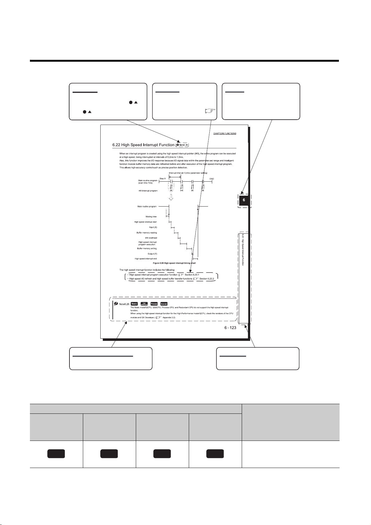
MANUAL PAGE ORGANIZATION
Note (detailed explanation)
ReferenceNote (icon)
The section in this manual or
another relevant manual that can
be referred to is shown with .
The chapter of the current page can be
easily identified by this indication on the
right side.
Chapter
The detailed note corresponding to each icon
is described.
Section title
The section number and title of the current
page can be easily identified.
The detailed explanation of "Note . " is
provided under the corresponding
"Note . " at the bottom of the page.
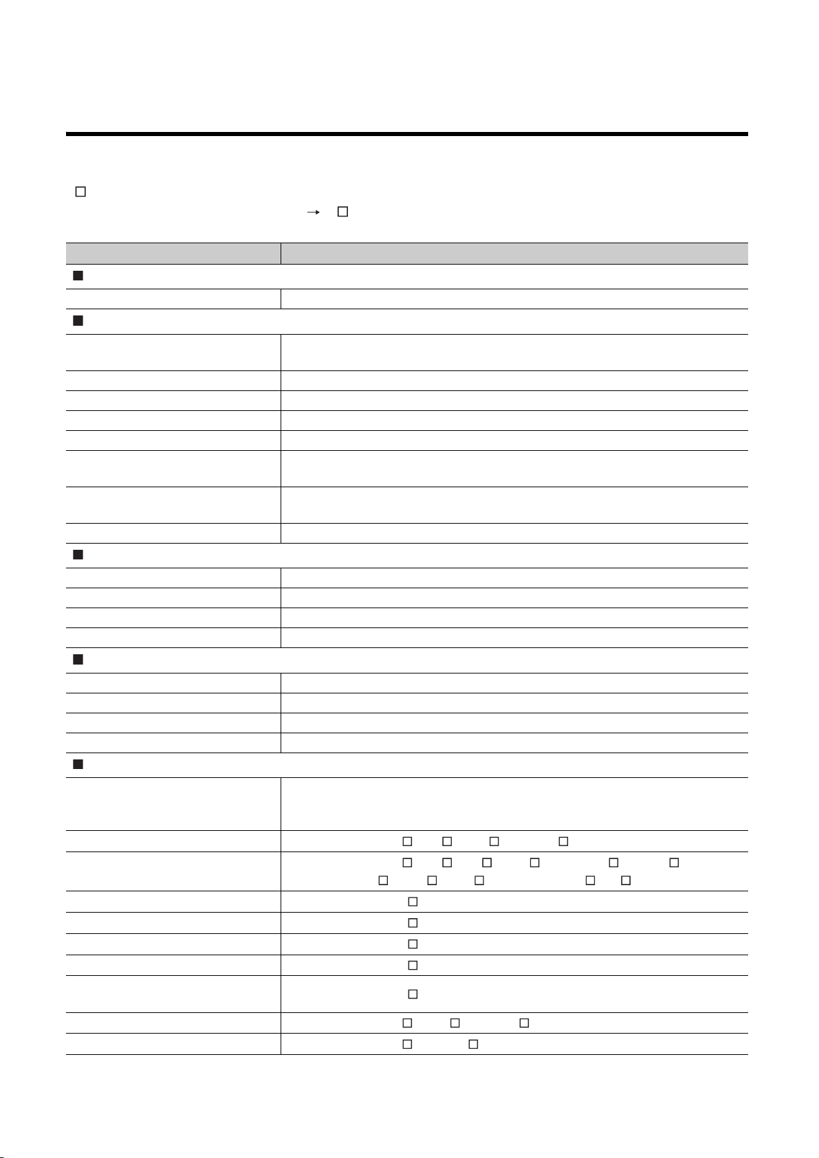
Basic
*The above page illustration is for explanation purpose only, and is different from the actual page.
Basic model
QCPU
Icons
High
Performance
model QCPU
Process CPU Redundant CPU
Description
A - 20
High
performance
Process
Redundant
Icons indicate that specifications
described on the page contain some
precautions.

In addition, this manual uses the following types of explanations.
Remark
In addition to description of the page, notes or functions that require special attention are described here.
The reference related to the page or useful information are described here.
A - 21
GENERIC TERMS AND ABBREVIATIONS
Unless otherwise specified, this manual uses the following generic terms and abbreviations.
*
indicates a part of the model or version.
(Example): Q33B, Q35B, Q38B, Q312B Q3 B
Generic term/abbreviation Description
Series
Q series Abbreviation for Mitsubishi MELSEC-Q series programmable controller
CPU module type
CPU module
Basic model QCPU Generic term for the Q00JCPU, Q00CPU, and Q01CPU
High Performance model QCPU Generic term for the Q02CPU, Q02HCPU, Q06HCPU, Q12HCPU, and Q25HCPU
Process CPU Generic term for the Q02PHCPU, Q06PHCPU, Q12PHCPU, and Q25PHCPU
Redundant CPU Generic term for the Q12PRHCPU and Q25PRHCPU
Motion CPU
PC CPU module
C Controller module Generic term for the Q06CCPU-V, and Q06CCPU-V-B, C Controller modules
CPU module model
QnHCPU Generic term for the Q02HCPU, Q06HCPU, Q12HCPU, and Q25HCPU
Qn(H)CPU Generic term for the Q02CPU, Q02HCPU, Q06HCPU, Q12HCPU, and Q25HCPU
QnPHCPU Generic term for the Q02PHCPU, Q06PHCPU, Q12PHCPU, and Q25PHCPU
QnPRHCPU Generic term for the Q12PRHCPU and Q25PRHCPU
Redundant CPU
Control system Primary system for control and network communication in the redundant system
Standby system Backup system in the redundant system
System A System to which the system A connector of tracking cable is connected
System B System to which the system B connector of tracking cable is connected
Base unit type
Base unit
Main base unit
Extension base unit
Slim type main base unit
Redundant power main base unit
Redundant power extension base unit
Redundant type extension base unit
Multiple CPU high speed main base
unit
Redundant base unit
Redundant power supply base unit
Generic term for the Basic model QCPU, High Performance model QCPU, Process CPU, and
Redundant CPU
Generic term for Mitsubishi motion controllers, Q172CPUN, Q173CPUN, Q172HCPU,
Q173HCPU, Q172CPUN-T, Q173CPUN-T, Q172HCPU-T, and Q173HCPU-T
Generic term for MELSEC-Q series PC CPU modules, PPC-CPU686(MS)-64,
PPC-CPU686(MS)-128, and PPC-CPU852(MS)-512 manufactured by CONTEC Co., Ltd.
Generic term for the main base unit, extension base unit, slim type main base unit, redundant
power main base unit, redundant power extension base unit, and multiple CPU high speed
main base unit
Generic term for the Q3 B, Q3 SB, Q3 RB, and Q3 DB
Generic term for the Q5 B, Q6 B, Q6 RB, Q6 WRB, QA1S5 B, QA1S6 B,
QA1S6ADP+A1S5 B/A1S6 B, QA6 B, and QA6ADP+A5 B/A6 B
Another name for the Q3 SB
Another name for the Q3 RB
Another name for the Q6 RB
Another name for the Q6 WRB
Another name for the Q3 DB
Generic term for the Q3 RB, Q6 RB, and Q6 WRB
Generic term for the Q3 RB and Q6 RB
A - 22
Generic term/abbreviation Description
Base unit model
Q3 B
Q3 SB
Q3 RB
Q3 DB
Q5 B
Q6 B
Q6 RB
Q6 WRB
QA1S5 B
QA1S6 B
QA6 B
A5 B
A6 B
QA6ADP+A5 B/A6 B
QA1S6ADP+A1S5 B/A1S6 B
Power supply module
Power supply module
Q series power supply module
AnS series power supply module Generic term for the A1S61PN, A1S62PN, and A1S63P power supply modules
A series power supply module
Slim type power supply module Abbreviation for the Q61SP slim type power supply module
Redundant power supply module
Network
MELSECNET/H Abbreviation for the MELSECNET/H network system
Ethernet Abbreviation for the Ethernet network system
CC-Link Abbreviation for the Control & Communication Link
Memory card
Memory card Generic term for the SRAM card, Flash card, and ATA card
SRAM card Generic term for the Q2MEM-1MBS, Q2MEM-2MBS, and Q3MEM-4MBS SRAM cards
Flash card Generic term for the Q2MEM-2MBF and Q2MEM-4MBF Flash cards
ATA card Generic term for the Q2MEM-8MBA, Q2MEM-16MBA, and Q2MEM-32MBA ATA cards
Others
GX Developer
QA6ADP Abbreviation for the QA6ADP QA conversion adapter module
QA1S6ADP Abbreviation for the QA1S6ADP(-S1) Q-AnS base unit conversion adapter
Extension cable Generic term for the QC05B, QC06B, QC12B, QC30B, QC50B, and QC100B extension cables
Tracking cable Generic term for the QC10TR and QC30TR tracking cables for redundant systems
Battery
GOT
Generic term for the Q33B, Q35B, Q38B, and Q312B main base units
Generic term for the Q32SB, Q33SB, and Q35SB slim type main base units
Another name for the Q38RB main base unit for redundant power supply system
Generic term for the Q35DB, Q38DB and Q312DB multiple CPU high speed main base units
Generic term for the Q52B and Q55B extension base units
Generic term for the Q63B, Q65B, Q68B, and Q612B extension base units
Another name for the Q68RB extension base unit for redundant power supply system
Another name for the Q65WRB extension base unit for redundant power supply system
Another name for the QA1S51B extension base unit
Generic term for the QA1S65B and QA1S68B extension base units
Generic term for the QA65B and QA68B extension base units
Generic term for the A52B, A55B, and A58B extension base units
Generic term for the A62B, A65B, and A68B extension base units
Abbreviation for A large type extension base unit on which the QA6ADP is mounted
Abbreviation for A small type extension base unit on which the QA1S6ADP is mounted
Generic term for the Q series power supply module, slim type power supply module, and
redundant power supply module
Generic term for the Q61P-A1, Q61P-A2, Q61P, Q61P-D, Q62P, Q63P, Q64P, and Q64PN
power supply modules
Generic term for the A61P, A61PN, A62P, A63P, A68P, A61PEU, and A62PEU power supply
modules
Generic term for the Q63RP and Q64RP power supply modules for redundant power supply
system
Product name for SW D5C-GPPW-E GPP function software package compatible with the Q
series
Generic term for the Q6BAT, Q7BAT, and Q8BAT CPU module batteries, Q2MEM-BAT SRAM
card battery, and Q3MEM-BAT SRAM card battery
Generic term for Mitsubishi Graphic Operation Terminal, GOT-A*** series, GOT-F*** series,
and GOT1000 series
A - 23

CHAPTER1 OVERVIEW
The CPU module performs sequence control by executing programs.
This chapter describes the processing order in the CPU module, locations where the created programs are stored, and
devices and instructions useful for programming.
1.1 Processing Order in the CPU Module
The CPU module performs processing in the following order.
Power-on or reset
Initial processing
Refresh processing with
input/output modules
Program operation processing
Scan time
END processing
Figure 1.1 Processing order in the CPU module
(1) Initial processing ( Section 3.1)
The CPU module performs preprocessing required for program operations.
The preprocessing is performed only once when the module is powered on or reset.
(2) Refresh processing with input and output modules ( Section 3.2)
The CPU module takes on/off data from the input module or intelligent function module and outputs on/off data to
the output module or intelligent function module.
(3) Program operation processing ( Section 3.3)
The CPU module sequentially executes the program stored in the module from the step 0 to the END or FEND
instruction.
(4) END processing ( Section 3.4)
The CPU module performs refresh processing with network modules or communicates with external devices.
1 - 1
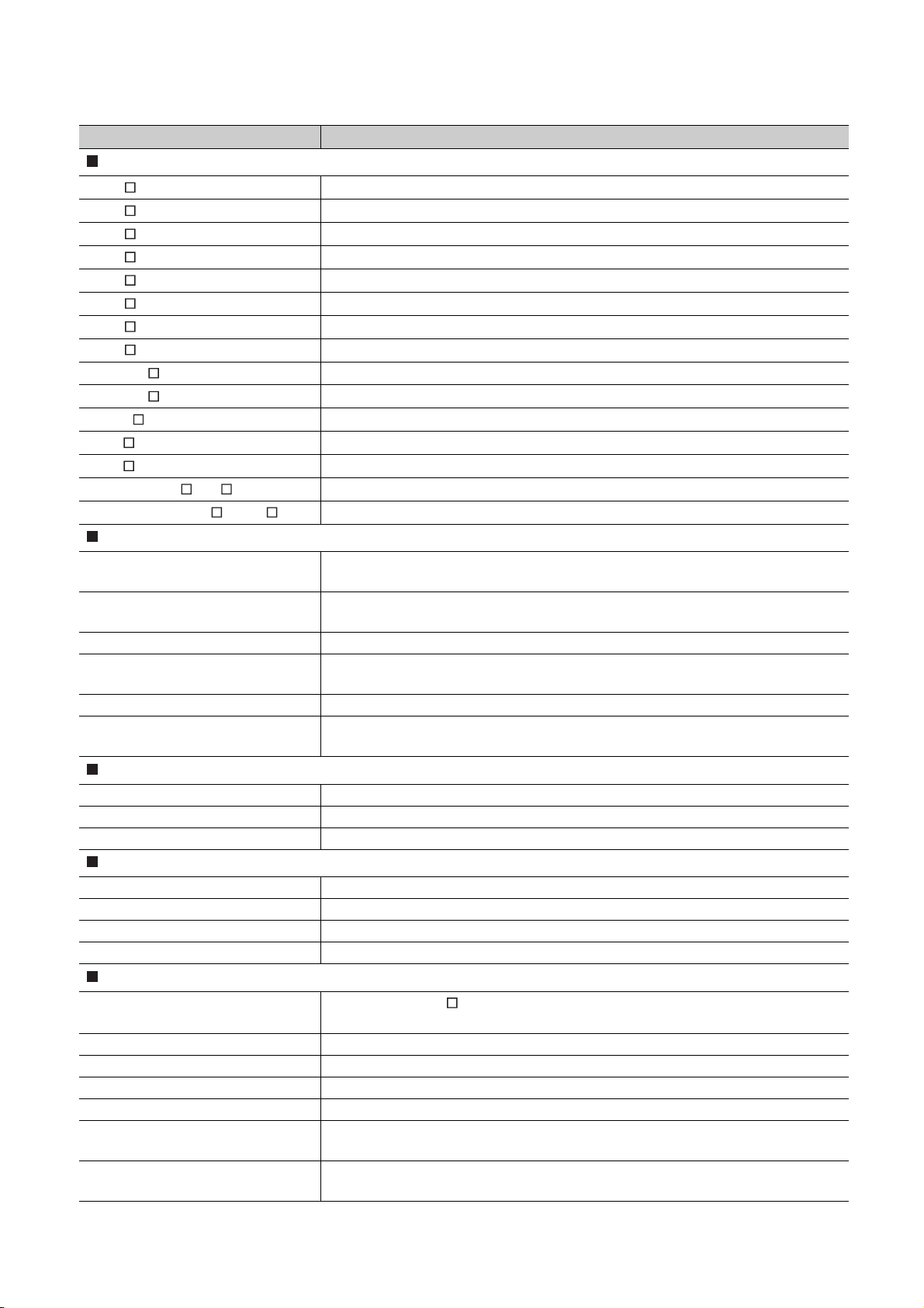
CHAPTER1 OVERVIEW
CPU module
The CPU module executes
the programs stored here.
Program memory
Parameter
Program
Device comment
Initial device value
Comments are stored
separately from the program.
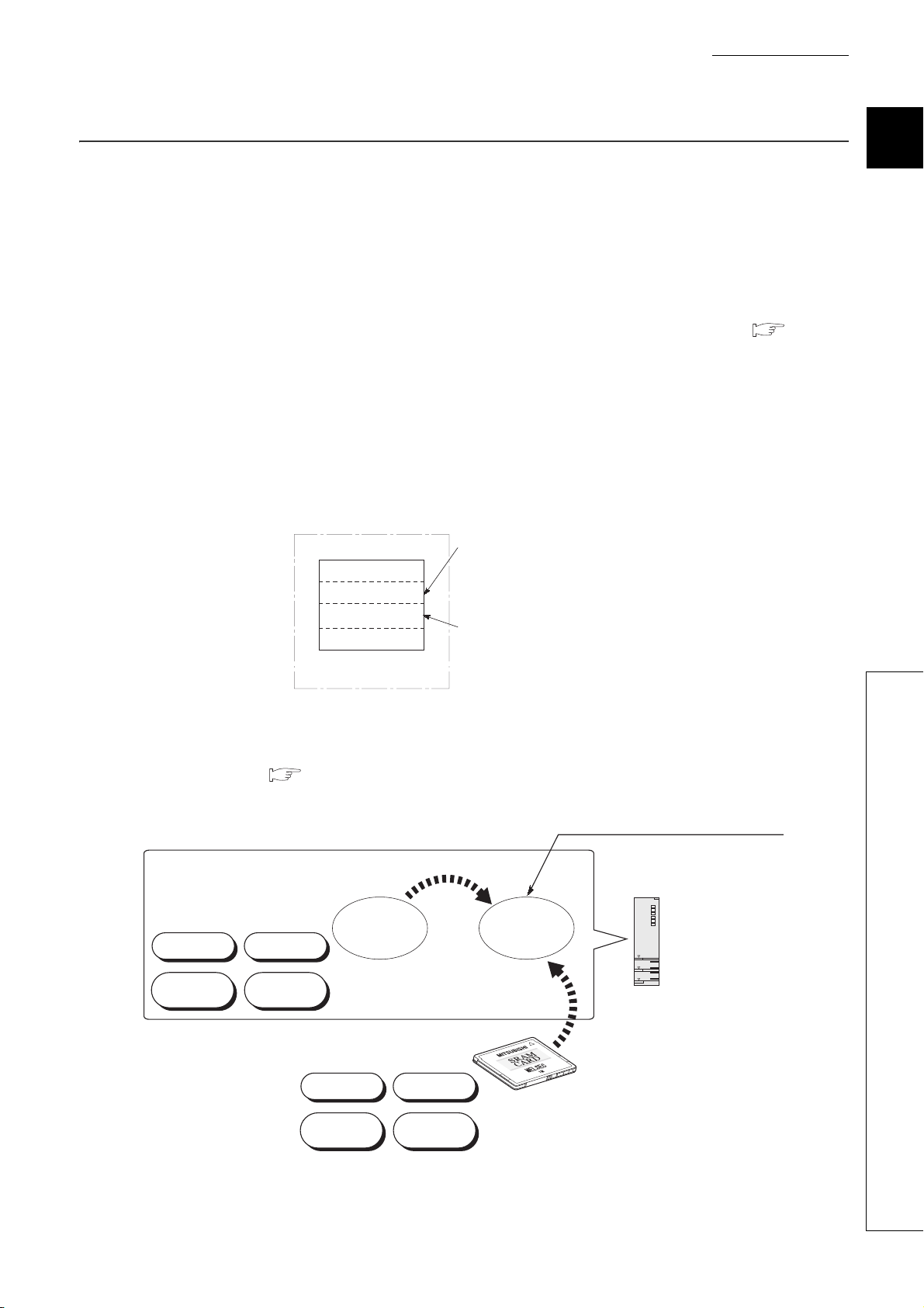
Standard
ROM
The CPU module executes the programs
booted from the standard ROM or
a memory card to here.
Boot
Boot
Parameter Program
Initial device
value
Device
comment
Device
comment
Parameter
Program
Initial device
value
CPU module
Memory card
*1
Program
memory
1.2 Storing and Executing Programs
This section describes where to store and how to execute the programs in the CPU module.
(1) Programming
Programs are created with GX Developer.
For details of program configuration and execution conditions, refer to CHAPTER 2.
(2) Storing programs
Created programs and set parameters are stored in the following memories of the CPU module. ( Section
5.1, Section 5.2)
• Program memory
• Standard ROM
• Memory card
(3) Executing programs
The CPU module executes the programs stored in the program memory.
1
Figure 1.2 Executing programs
To execute the programs stored in the standard ROM or a memory card, the programs need to be booted to the
program memory ( Section 5.1.5) when the CPU module is powered off and then on or reset.
1.2 Storing and Executing Programs
Figure 1.3 Executing programs by performing a boot operation
1 - 2

1.3 Structured Programming
Note1.1
The Basic model QCPU cannot store multiple programs, structured programming by dividing into multiple files is not
available.
P8
RET
RET
Y10
Y11
Y12
P1
END
FEND
CALL P1
IRET
I0
Main routine
program
Subroutine
program 1
Subroutine
program 2
Interrupt program
The programs to be executed in the CPU module can be structured in the following two ways.
• In one program
• By dividing into multiple files
(1) Structuring in one program
Structured programming is available by creating one program as a collection of three program sections: main rou-
tine program ( Section 2.2.1), subroutine program ( Section 2.2.2), and interrupt program
( Section 2.2.3)
Note1.1Note1
Note1
1 - 3
Figure 1.4 Structuring in one program
Basic
CHAPTER1 OVERVIEW
GX Developer
CPU module
Multiple programs can be stored
by changing the file name.
File name: PARAM
Parameter Program Program
Device
comment
File name: ABC File name: ABC File name: DEF
Carrying in
Carrying out
Manufacturing
Assembly
Program memory/standard ROM/memory card
Processing contents
are divided according
to the processes.
Program A
Program B
Program C
Program D
Program A to D
will be executed
in the specified
order.
*2
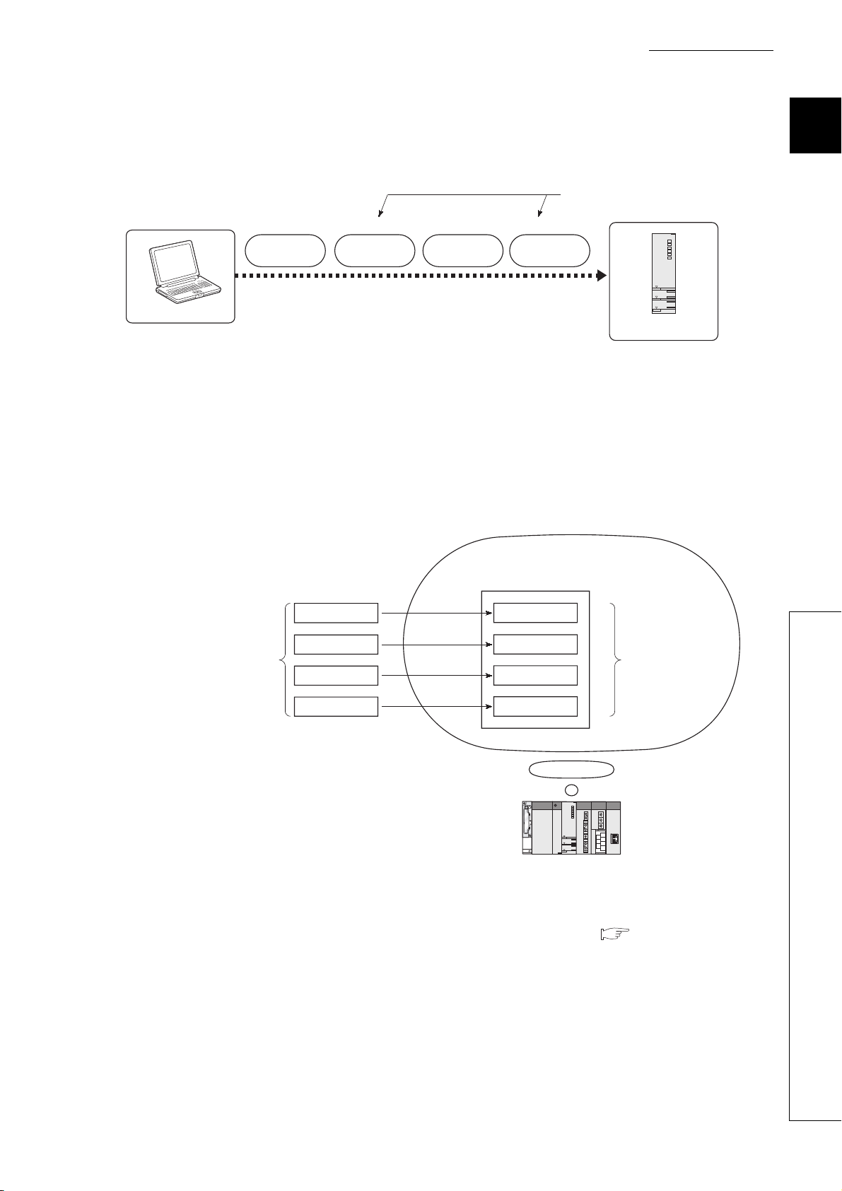
(2) Structuring by dividing into multiple files
A program is stored in a file.
Changing the file name allows the CPU module to store multiple programs.
Figure 1.5 Structuring by dividing into multiple files
Dividing into multiple files according to the processes or functions enables simultaneous programming by two or
more designers. Managing the files separately eases reuse and utilization to other programs.
Structured programming is efficient in this way because only the corresponding file needs to be modified or
debugged in case of change in the specifications.
(a) Dividing into multiple files according to the processes
*1
1
Figure 1.6 Dividing into multiple files according to the processes
*1: The processing contents divided according to the processes can further be divided and managed according to the func-
tions.
*2: The execution order can be set in the Program tab of the PLC parameter dialog box. ( Section 2.3(2))
1.3 Structured Programming
1 - 4
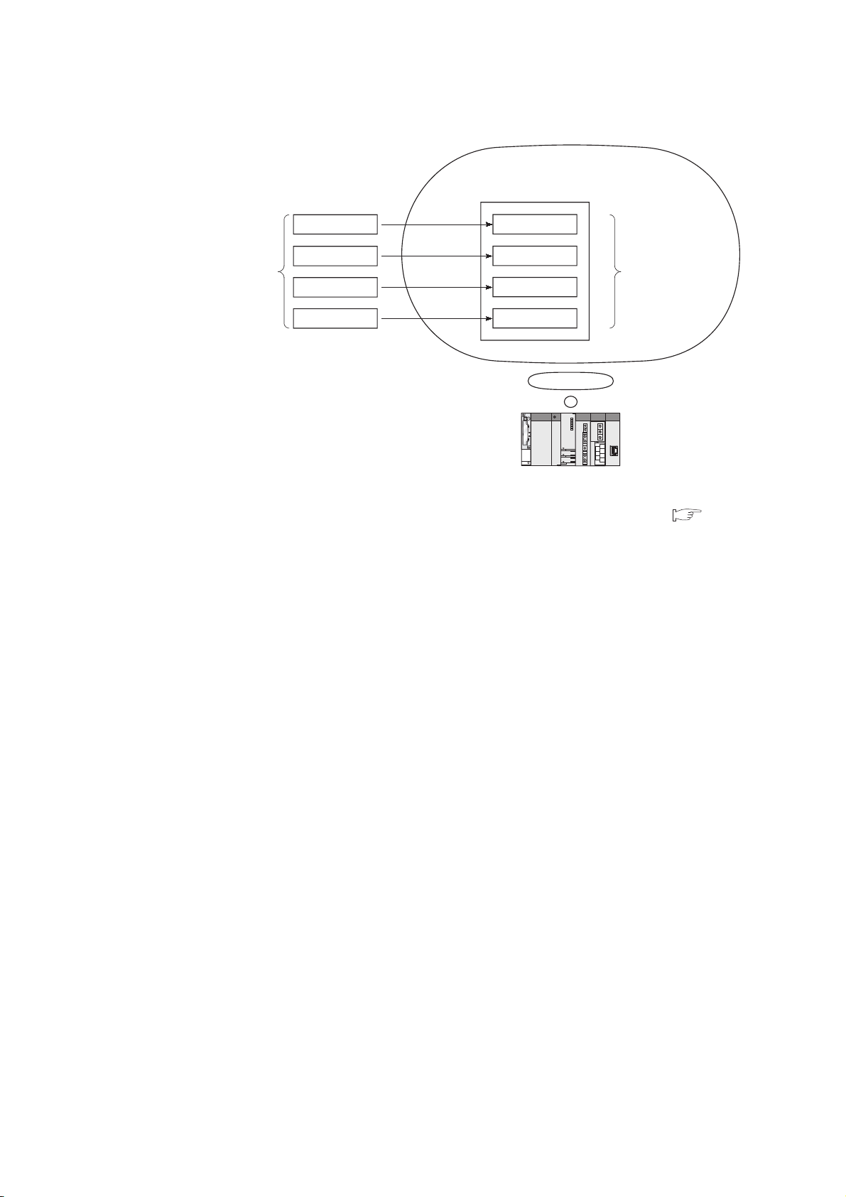
(b) Dividing into multiple files according to the functions
Program memory/standard ROM/memory card
Initial processing
Processing contents
are divided according
to the functions.
Figure 1.7 Dividing into multiple files according to the functions
*1: The execution order and conditions can be set in the Program tab of the PLC parameter dialog box ( Section
2.3(2))
Main processing
Communication
processing
Error processing
Program A
Program B
Program C
Program D
The execution order
and conditions for
program A to D
can be set.
*1
1 - 5
 Loading...