

MITSMI MM1438 Datasheet
MITSUMI
1432
8567
VSOP-8B
MITSUMI
IC for Control of Lithium-ion Betteries Charging MM1438
IC for Control of Lithium-ion Betteries Charging
Monolithic IC MM1438
Outline
This IC is used to control charging of lithium-ion batteries consisting of a single cell. It is a modification of the
previous MM1332 charging-control IC, with improved charging voltage accuracy and a smaller package.
Features
1. Charging voltage accuracy (Ta=25°C) ±25mV/cell
2. Charging voltage accuracy (Ta=0 to 50°C) ±30mV/cell
3. Consumption current (charging on) 250µA typ.
4. Consumption current (charging off) 2µA typ.
5. Low-voltage detection 2.15V typ.
6. Leakage current between CEL and CS 1µA max.
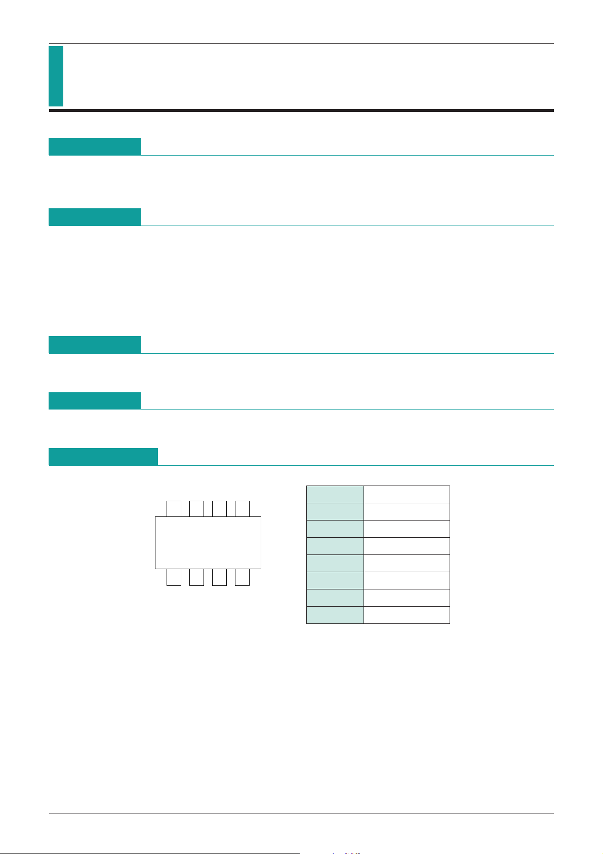
Package
VSOP-8B
Applications
IC for control of lithium-ion batteries charging.
Pin Assignment
1 GND
2 LV
3 SW2
4 SW1
5 V
6 EXT
7 CEL
8 CS
CC

MITSUMI
MITSUMI
Block Diagram
IC for Control of Lithium-ion Betteries Charging MM1438
Pin Description
Pin No. Pin name I/O
1 GND Input Ground pin
Low voltage detection circuit output pin
2 LV Output
ON with NPN-Tr open collector output at low voltage
Low voltage detection circuit ON/OFF control input pin
3 SW2 Input
SW2 = V
CC: OFF, SW2 = GND: ON
ON/OFF control input pin for the IC
4 SW1 Input
5 V
CC Input Power supply input pin
6 EXT Output
SW1 = V
Charging control output pin Controls external PNP-Tr to control charging.
CC: OFF, SW1 = GND: ON
Battery voltage input pin
7 CEL Input
Detects battery voltage and controls rated voltage to the prescribed voltage value.
Current detection pin
8 CS Input Detects current by drop in external resistor voltage and controls rated current.
Current value can be set at 0.1V/R1 typ.
Pin Description

MITSUMI
IC for Control of Lithium-ion Betteries Charging MM1438
Absolute Maximum Ratings
(Ta=25°C)
Item Symbol Ratings Unit
Storage temperature T
Operating temperature T
Power supply voltage V
CFL pin input voltage V
CC max.
CEL max.
SW input voltage V
Allowable loss Pd 300 mW
Recommended Operating Conditions
Item Symbol Ratings Unit
Operating temperature T
Charging control operating voltage
Note: Operating voltage minimum value is during rated current control.
STG
OPR
SW
OPR
-
40~+125 °C
-
20~+70 °C
-
0.3~+18 V
-
0.3~+13 V
-
0.3~VCC+0.3 V
-
20~+70 °C
VOPR 2.5~+17 V
Electrical Characteristics
(Except where noted otherwise, Ta=25°C, VCC=5V, SW3 : A, SW6 : A, SW7 : A)
Item Symbol Measurement conditions Min. Typ. Max. Unit
Consumption current 1 I
Consumption current 2 I
Output voltage 1 V
Output voltage 2 V
Current limit V
CC1 VSW1=VSW2=0V (Charge : ON) 250 400 µA
CC2 VSW1=VSW2=VCC (Charge : OFF) 2 10 µA
O1 Ta=25°C 4.100 4.125 4.150 V
O2 Ta=0~50°C 4.095 4.125 4.155 V
CL 90 100 110 mV
Inflow current between
CEL1 3.0 5.0 7.0 µA
CEL-CS during operation
Leak current between CEL-CS
SW1 input current I
SW1 input voltage L V
SW1 input voltage H V
Low voltage detection voltage
SW2 input current I
SW2 input current L V
SW2 input current H V
I
ICEL2 VCC=0V or OPEN 0.01 1 µA
SW1 20 30 µA
L1 Charge : ON
H1 Charge : OFF
-
0.3 2.0 V
VCC-
0.1 VCC+0.3
LV 2.0 2.15 2.3 V
SW2 20 30 µA
L2 Low voltage detection circuit: ON
H2 Low voltage detection circuit: OFF
-
0.3 2.0 V
VCC-
1.0 VCC+0.3
Low voltage detection
LV 0.5 µA
output leak current
I
Low voltage detection
LV ISINK=1mA 0.2 0.4 V
output saturation voltage
V
EXT pin inflow current IEXT 10 20 mA
EXT pin output voltage V
EXT For no load 0.3
VCC-
Note 1: Please insert a capacitor of several µF between power supply and ground when using.
Note 2: Be sure that CS pin potential does not fall below
-
0.5V.
Note 3: If the IC is damaged and control is no longer possible, its safety can not be guaranteed. Please
protect with something other than this IC.
0.3
V
V
V
 Loading...