

MITSMI MM1421 Datasheet
MITSUMI
Protection of Lithium-Ion Batteries MM1421
Protection of Lithium-Ion Batteries
Monolithic IC MM1421
Outline
This IC is used to protect single-cell lithium-ion batteries. It adopts an ultra-compact package and has the
functions of previous models, with functions for overcharge detection, overdischarge detection and
overcurrent detection. A dead time can be set externally.
Features
1. Overcharge detection voltage accuracy (0°C to 50°C) ±25mV/cell
2. Consumption current (Vcell=3.6V) 10.0µA typ.
3. Consumption current (Vcell=1.9V) 0.1µA typ.
4. Overcharge sensing dead time can be set externally
5. Overdischarge reset reset by charging
Package
SOT-26A
Applications
IC for protection of single-cell lithium-ion batteries.
MITSUMI
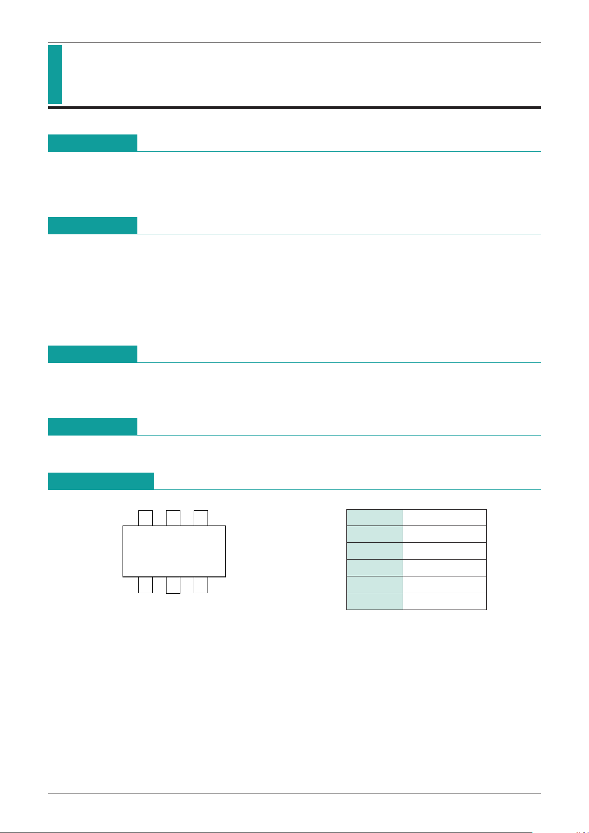
Pin Assignment
123
654
SOT-26A
1 VM
2 V
CC
3 TD
4 CO
5 GND
6 DO
MITSUMI
Protection of Lithium-Ion Batteries MM1421
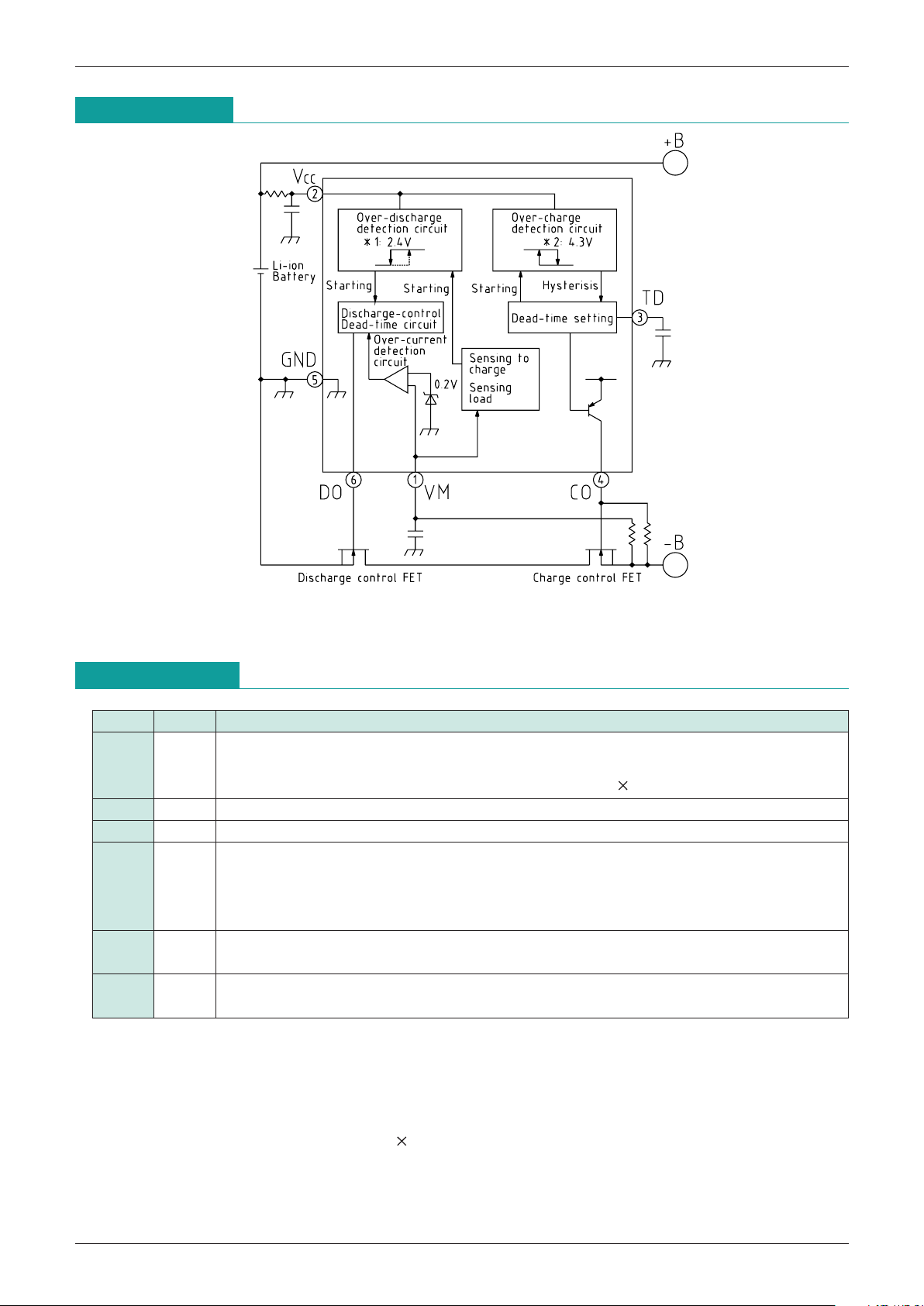
Block Diagram
Note 1 : Overdischarge voltage
Note 2 : Overcharge voltage
Pin Description
Pin No.
Pin Name
Function
1 V
M
Overcurrent detection input pin. Detects discharge current by connection to charging control
FET source pin.
Discharge current = (voltage between V
M
and GND) / (FET 2 ON resistance)
2 VCC Positive power supply pin.
3 TD Overcharge detection dead time setting pin.
4 CO
Charging control FET (N-ch) gate connection pin. An external resistor (910kΩ) is required
between gate and source. Turns off charging control FET (N-ch) for overcharge mode
(during charging) and overdischarge mode. Also, overcharge mode (during discharge)
turns charging control FET (N-ch) ON, and suppresses FET power consumption.
5 GND
Negative power supply pin. Also, negative input pin for battery connected between V
CC and
GND.
6 DO
Discharge control FET (N-ch) gate connection pin. Turns gate OFF for overdischarge
mode and overcurrent mode. Turns gate ON for overcharge mode and normal mode.
(1) Overcharge mode: Battery voltage > overcharge detection voltage
(2) Normal mode: Overdischarge detection voltage < battery voltage <overcharge detection voltage
Discharge current < overcurrent detection level
(3) Overdischarge mode: Overdischarge detection voltage > battery voltage
(4) Overcurrent mode: Discharge current > overcurrent detection level, voltage between V
M and GND =
discharge current FET ON resistance
(discharge/charge control FET)
MITSUMI
Protection of Lithium-Ion Batteries MM1421
MITSUMI
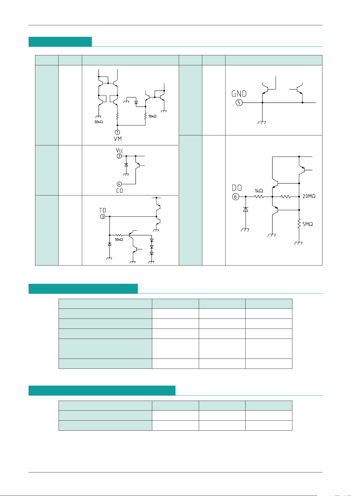
Pin Assignment
Pin No.
Pin name
Equivalent circuit diagram Pin No.
Pin name
Equivalent circuit diagram
1 V
M 5 GND
6 DO
2 V
CC
4 CO
3 TD
Absolute Maximum Ratings
(Ta=25°C)
Item Symbol Ratings Unit
Storage temparature T
STG
-
40~+125 °C
Operating temparature T
OPR
-
20~+70 °C
Supply voltage V
CC max.
-
0.3~+18 V
CO pin voltage V
CO max.
V
CC
-
28~VCC V
V
M pin voltage VVM max.
Allowable loss Pd 200 mW
Recommended Operating Conditions
Item Symbol Ratings Unit
Operating temparature T
OPR
-
20~+70 °C
Power supply voltage V
OP +1.8~+10 V
 Loading...