

MITSMI MM1412 Datasheet
MITSUMI
1432
8567
VSOP-8A
MITSUMI
Protection of Lithium-Ion Batteries MM1412
Protection of Lithium-Ion Batteries
Monolithic IC MM1412
Outline
This IC is used to protect lithium-ion batteries consisting of two cells. It adopts a compact package and has
the functions of previous models, with functions for overcharge detection, overdischarge detection and
overcurrent detection. A dead time can be set externally.
Features
1. Overcharge detection voltage accuracy (0°C to 50°C) ±25mV/cell
2. Consumption current (Vcell=4.5V) 150µA typ.
3. Consumption current (Vcell=3.5V) 15.0µA typ.
4. Consumption current (Vcell=1.9V) 0.5µA typ.
5. Overcharge sensing dead time can be set externally.
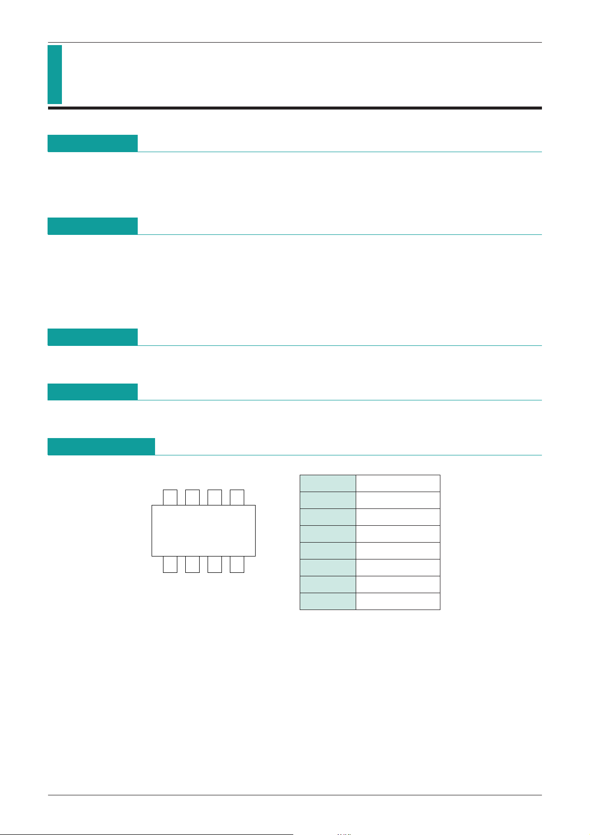
Package
VSOP-8A
Applications
IC for protection of lithium-ion batteries consisting of two cells.
Pin Assignment
1 OC
2 GD
3 CS
4 GND
5 TD
6 VL
7 V
8 VH
CC
MITSUMI
MITSUMI
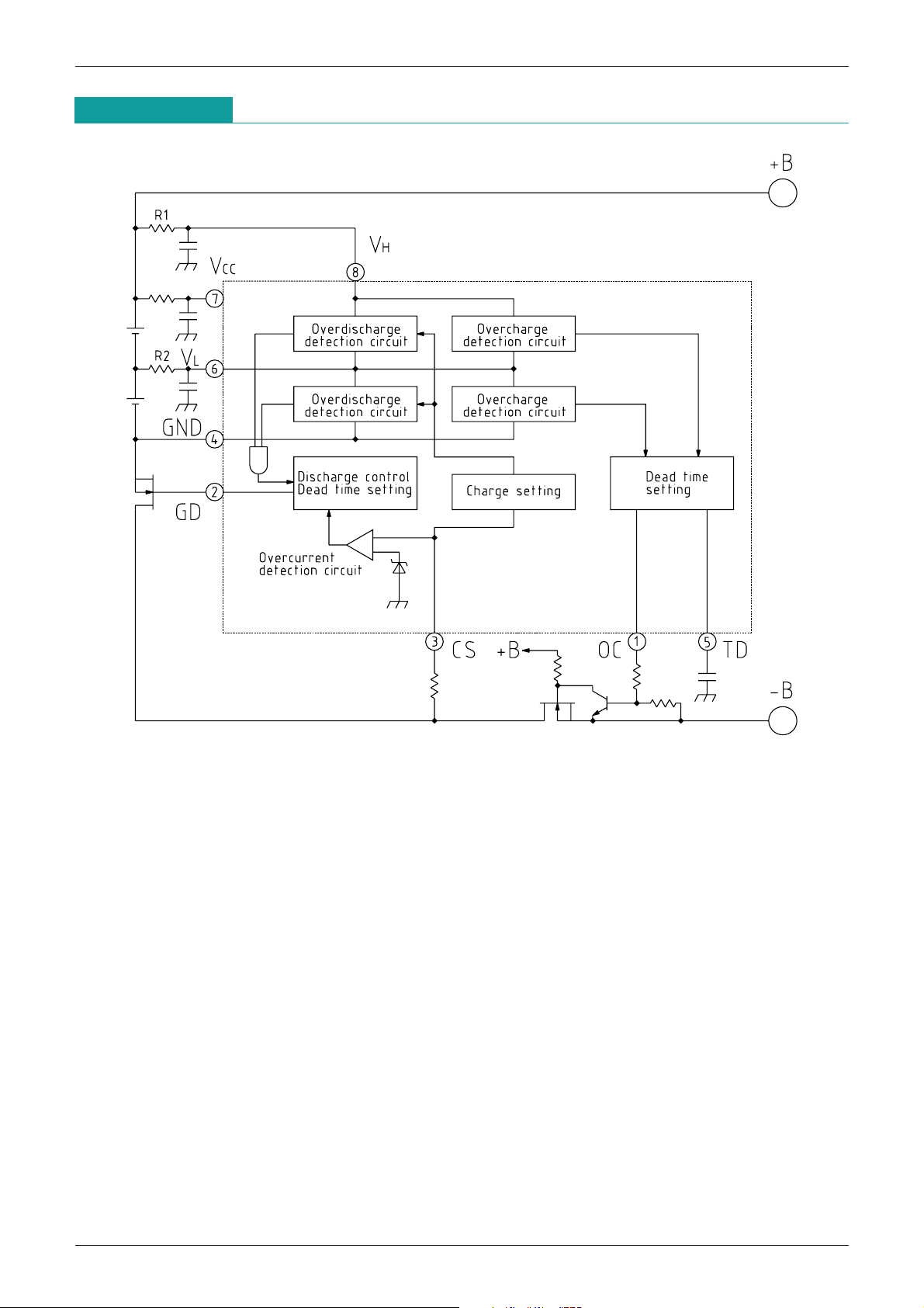
Block Diagram
Protection of Lithium-Ion Batteries MM1412

MITSUMI
Pin Description
Protection of Lithium-Ion Batteries MM1412
Pin No.
Pin name
Functions
Overcharge detection output pin
PNPT
R open collector output
1 OC
Overcharge mode: ON
Normal mode, overdischarge mode, overcurrent mode: OFF
Discharge control FET (N-ch) control output pin
2 GD Normal mod, overcharge mode: H
Overdischarge mode, overcurrent mode: L
Overcurrent detection input pin
Monitors discharge current equivalently by the voltage drop between discharge control FET source
3 CS
and drain. Stops discharge when voltage between CS pin and GND pin goes above overcurrent
detection threshold value, and holds until load is released.
4 GND Ground pin, or lower cell load negative pole input pin.
Overcharge detection dead time setting pin
5 TD
Dead time can be set by adding a capacitor between TD and GND pins.
Battery intermediate potential input pin
6 VL
Connection pin for lower cell positive electrode side and upper cell negative electrode side.
7 V
CC Power supply input pin
8 VH Upper cell positive electrode input pin
Note: Mode Descriptions
(1) Overcharge mode
Either H cell or L cell battery voltage exceeds overcharge detection voltage. Overcharge detection
operation delay can be set by the dead time setting pin.
(2) Normal mode
Both H and L cell battery voltages exceed overdischarge detection voltage and are less than
overcharge detection voltage.
(3) Overdischarge mode
Either H or L cell battery voltage is less than overdischarge detection voltage.
Overdischarge detection dead time is set internally. Overdischarge mode is released when charging
causes voltage to rise above overdischarge detection voltage. Also, when battery voltage goes above
overdischarge release voltage, it resets without charging, but the value is set high. (This function is
included in case charging can not be detected. Also, this release voltage has a temperature coefficient
of
-
6mV/°C.)
(4) Overcurrent mode
Voltage between CS and GND exceeds overcurrent detection voltage during discharge.
 Loading...