

MITSMI MM1407 Datasheet
MITSUMI
Audio MM1407
Audio
Monolithic IC MM1407
Outline
This audio IC was developed for notebook PCs and allows major reduction of amp circuit board area. (To
conform to PC98, includes built-in speaker drive amp, headphone amp, line amp. stereo/monaural switching,
DC voltage control electronic volume, watchdog, logic control function.)
Features
(1) Speaker amp: Stereo BTL output 0.7W (when VCC = 5.0V, RL = 8Ω)
(2) Electronic volume control (
THD1 = 0.5% (when V
THD2 = 0.1% (when V
(4) Line amp: Mixes 4 inputs ( 2ch signals and outputs on 3 outputs ( 2ch. Stereo/monaural switching
possible on one line. THD = 0.1% (when V
(5) Microphone amp: Switch pin selects 1 of 4 inputs
(6) Logic control: Speaker, headphone and line amp (including microphone amp and mix amp) logic
controllable. Current consumption 300µA during power save mode.
-
60 ~ +20dB). THD = 0.5% (when POUT = 300mW, RL = 8Ω)
OUT = 100mVrms, RL = 16Ω)
OUT = 1VmVrms, RL = 10kΩ)
OUT = 1Vrms, RL = 10kΩ)
Package
QFP-80B
Applications
(1) Notebook PC audio control

MITSUMI
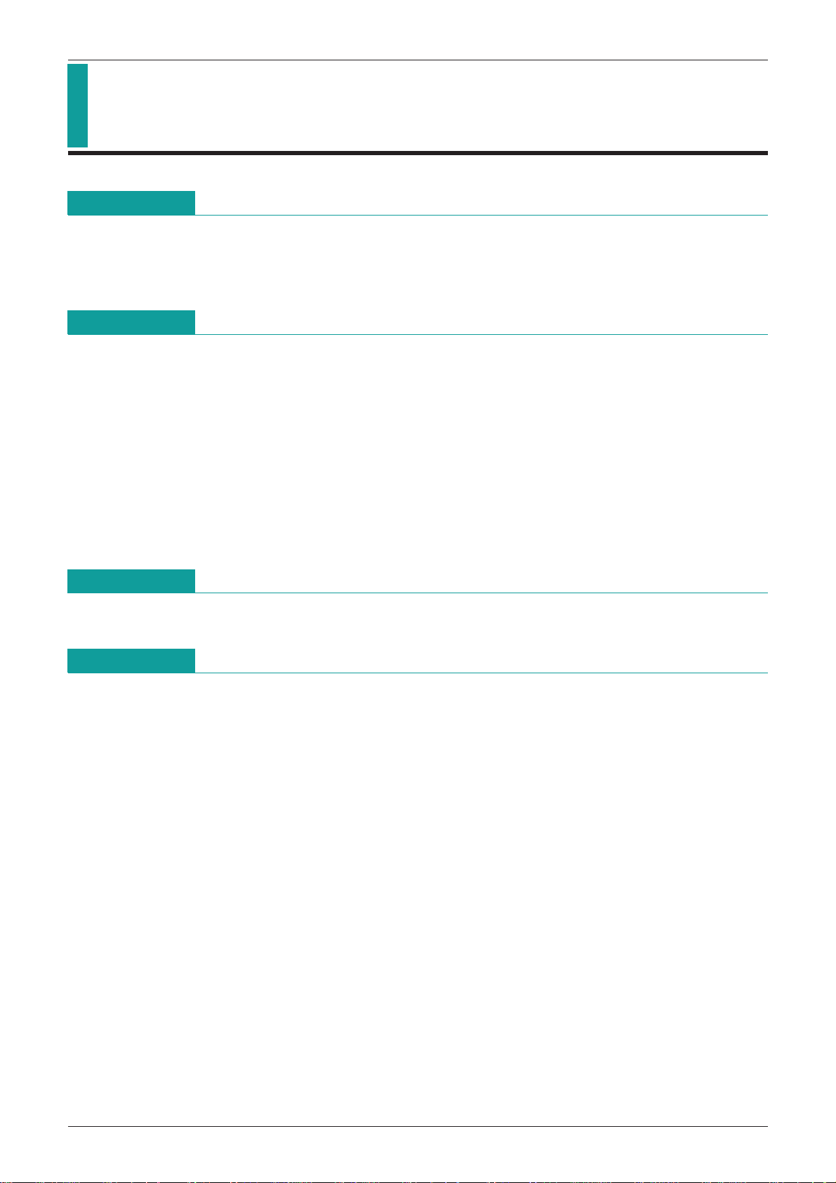
Block Diagram
Audio signal control section
(Except where otherwise indicated amp gain is 0dB.)
Audio MM1407
MITSUMI
Audio MM1407
HP signal control section
SP signal
control
section
Digtal signal
control section
MITSUMI
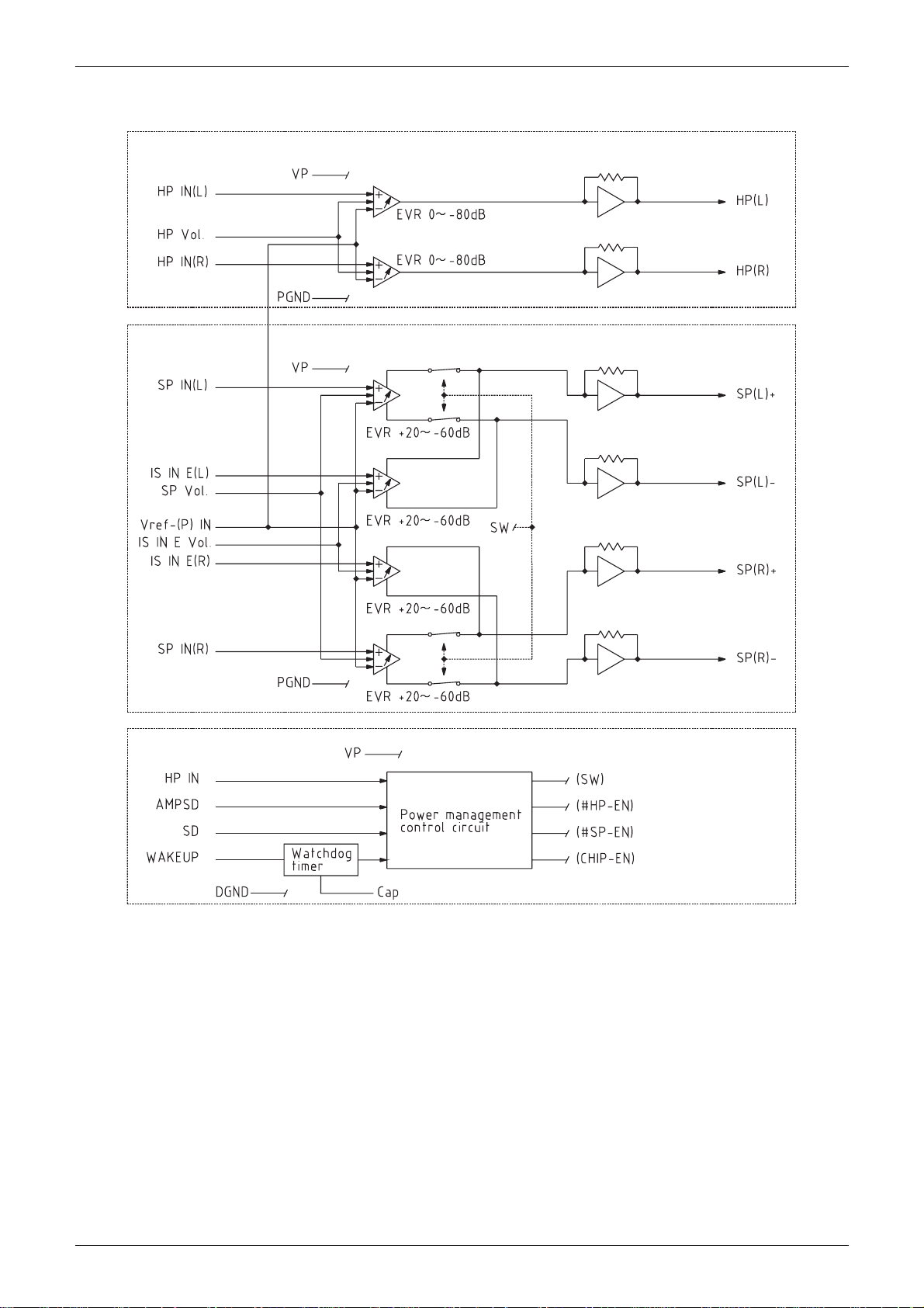
Pin Description
Audio MM1407
60 57 5559 58 56 53952
54
61
62
63
64
65
66
67
68
69
70
71
72
73
74
75
76
77
78
79
80
13 762458
105111501249134814471546164517441843194220
QFP-80B
41
40
39
38
37
36
35
34
33
32
31
30
29
28
27
26
25
24
23
22
21
1 Vref-IN 21 IS IN A (R) 41 HP (R) 61 HP IN (L)
2 Aux E (L) 22 IS IN B (R) 42 V
CC1 62 IS IN E (L)
3 Aux D (L) 23 IS IN C (R) 43 PGND1 63 SP IN (L)
4 Aux C (L) 24 IS IN D (R) 44 SP (R)+ 64 HP VOL
5 Aux B (L) 25 IS SEL 45 VP1 65 Mic
6 Aux A (L) 26 Line out (R) 46 VP2 66 Mic
7 Aux Mix (L) 27 Pre out A (R) 47 SP (R)
-
67 Mic-1
8 Line in B (L) 28 Pre out B (R) 48 PGND2 68 Mic
9 Line in A (L) 29 Mono SEL 49 GND1 69 Mic
10 Line Mix (L) 30 Cap 50 GND2 70 Mic
-
sel 0
-
sel 1
-
2
-
4
-
3
11 AGND1 31 WAKEUP 51 PGND3 71 Mic out
12 Line Mix (R) 32 AMPSD 52 SP (L)+ 72 AGND2
13 Line in A (R) 33 SD 53 VP3 73 Pre out B (L)
14 Line in B (R) 34 HP
15 Aux Mix (R) 35 DGND 55 SP (L)
16 Aux A (R) 36 VD 56 PGND4 76 AV
-
IN 54 VP4 74 Pre out A (L)
-
75 Line out (L)
CC
17 Aux B (R) 37 Vref (P)-IN 57 VCC2 77 IS IN D (L)
18 Aux C (R) 38 SP IN (R) 58 HP (L) 78 IS IN C (L)
19 Aux D (R) 39 IS IN E (R) 59 IS IN E VOL 79 IS IN B (L)
20 Aux E (R) 40 HP IN (R) 60 SP VOL 80 IS IN A (L)
MITSUMI
Pin Description
Audio MM1407
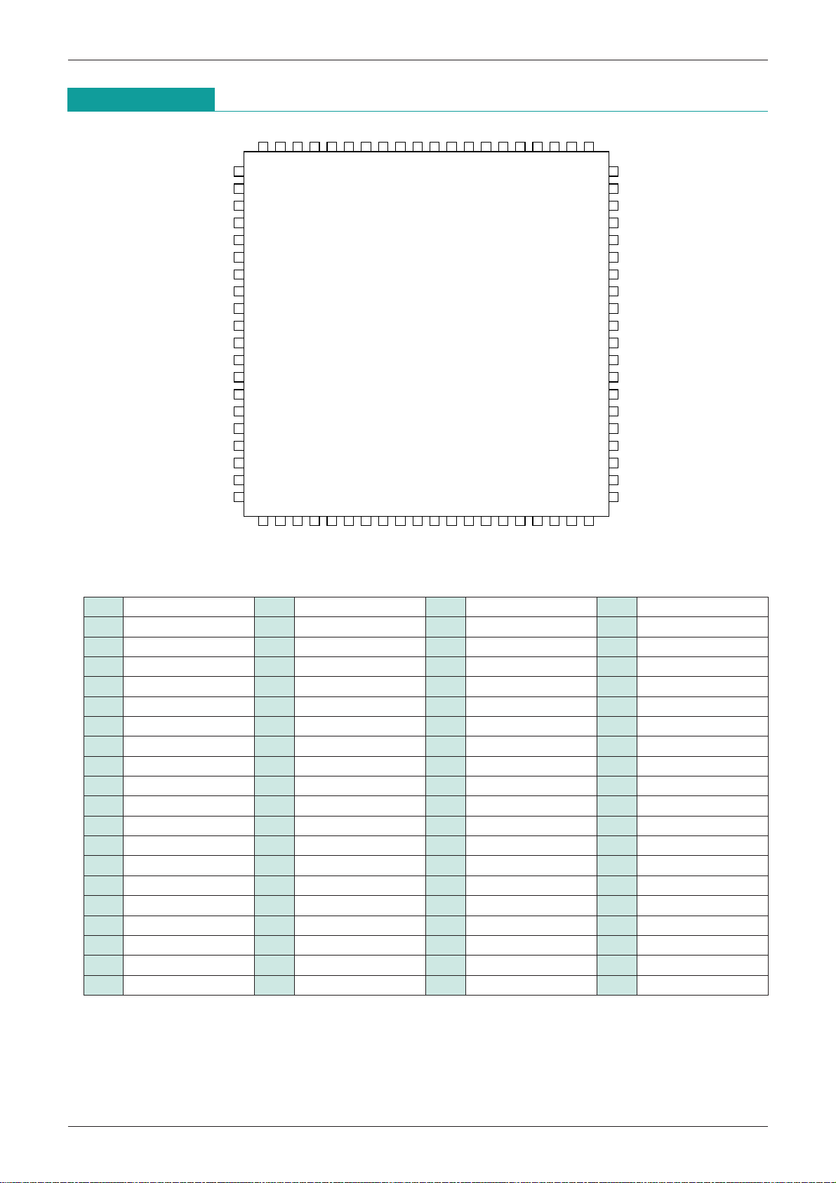
Pin No.
Pin name
1 Vref
2 Aux E (L) Input Audio signal control 1 of 5 Aux Mix (L) (add amp) inputs.
3 Aux D (L) Input Audio signal control 1 of 5 Aux Mix (L) (add amp) inputs.
4 Aux C (L) Input Audio signal control 1 of 5 Aux Mix (L) (add amp) inputs.
5 Aux B (L) Input Audio signal control 1 of 5 Aux Mix (L) (add amp) inputs.
6 Aux A (L) Input Audio signal control 1 of 5 Aux Mix (L) (add amp) inputs.
7
Aux Mix (L)
8
Line In B (L)
9
Line In A (L)
10
Line Mix (L)
11 AGND1 GND Audio signal control
12
Line Mix (R)
13
Line In A (R)
14
Line In B (R)
15
Aux Mix (R)
16 Aux A (R) Input Audio signal control 1 of 5 Aux Mix (R) (add amp) inputs.
17 Aux B (R) Input Audio signal control 1 of 5 Aux Mix (R) (add amp) inputs.
18 Aux C (R) Input Audio signal control 1 of 5 Aux Mix (R) (add amp) inputs.
19 Aux D (R) Input Audio signal control 1 of 5 Aux Mix (R) (add amp) inputs.
20 Aux E (R) Input Audio signal control 1 of 5 Aux Mix (R) (add amp) inputs.
21 IS IN A (R) Input Audio signal control
22 IS IN B (R) Input Audio signal control
23 IS IN C (R) Input Audio signal control
24 IS IN D (R) Input Audio signal control
25 IS Sel. Input (SW) Audio signal control
26
Line Out (R)
27
Pre Out A (R)
28
Pre Out B (R)
29 Mono Sel. Input (SW) Audio signal control
30 Cap
31 WAKEUP
32 AMPSD
33 SD
-
IN
Input/Output
Power supply
(reference)
Output Audio signal control Signal with Aux A ~ E (L) input added is output.
Input Audio signal control 1 of 2 Line In (L) (add amp) inputs.
Input Audio signal control 1 of 2 Line In (L) (add amp) inputs.
Output Audio signal control Signal with Aux A ~ B (L) input added is output.
Output Audio signal control Signal with Aux A ~ B (L) input added is output.
Input Audio signal control 1 of 2 Line In (R) (add amp) inputs.
Input Audio signal control 1 of 2 Line In (R) (add amp) inputs.
Output Audio signal control Signal with Aux A ~ E (R) input added is output.
Output Audio signal control
Output Audio signal control
Output Audio signal control
Input (logic)
Input (logic)
Input (logic)
Input (logic)
Section Function
Audio signal control Applies audio signal control reference potential.
Audio signal control ground pin. (except for Mic amp)
1 pin of 4 amp inputs that output to Line Out (R), Pre Out
A (R), Pre Out B (R), (L).
1 pin of 4 amp inputs that output to Line Out (R), Pre Out
A (R), Pre Out B (R), (L).
1 pin of 4 amp inputs that output to Line Out (R), Pre Out
A (R), Pre Out B (R), (L).
1 pin of 4 amp inputs that output to Pre Out A (R), Pre
Out B (R), (L).
This pin selects either of two inputs IS IN A (R) or IS IN
B (R). (See Figure A)
A signal that has IS IN A (R) or B (R) or IS IN C (R)
added is output.
A signal that has IS IN A (R) or B (R) or IS IN C (R) or
IS IN D (R) added is output.
During Mono Sel. R Stereo selection, a signal that has IS IN A
(R) or B (R) or IS IN C (R) or IS IN D (R) added is output.
During Mono Sel. R Mono selection, a signal that is a mixture of
a signal with (R) input added and then lowered 9dB and a signal
that with (L) input added and lowered 9dB.
This pin switches Pre Out B (L), (R) Stereo and Mono
output. (See Figure A)
This pin sets clock monitoring time for the watchdog timer
Digital signal control
Digital signal control 1 of 4 logic circuit inputs. (See Figure D)
Digital signal control 1 of 4 logic circuit inputs. (See Figure D)
Digital signal control 1 of 4 logic circuit inputs. (See Figure D)
circuit. Clock monitoring time is determined by the capacitor
time constant connected to this pin. (See Figure C)
MITSUMI
Audio MM1407
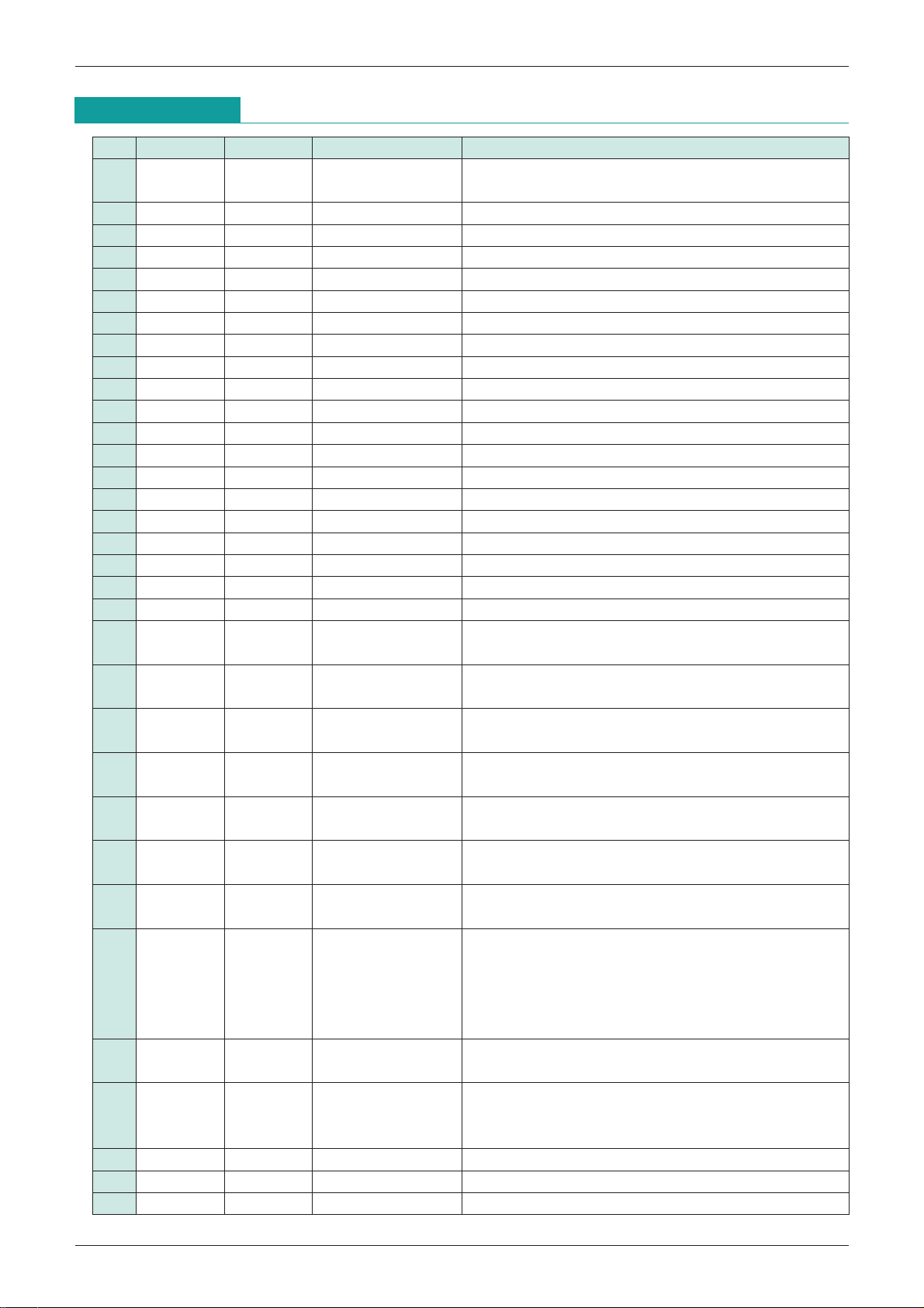
Pin No.
Pin name
34 HP
35 DGND GND
36 VD
37 Vref
38 SP IN (R) Input SP signal control
39 IS IN E (R) Input SP signal control
40 HP IN (R) Input HP signal control HP amp (R
41 HP (R) Output HP signal control HP amp (R
42 V
43 PGND1 GND
44 SP (R) + Output SP signal control SP amp (R
45 VP1
46 VP2
47 SP (R)
48 PGND2 GND
49 GND1 GND
50 GND2 GND
51 PGND3 GND
52 SP (L) + Output SP signal control SP amp (L
53 VP3
54 VP4
55 SP (L)
56 PGND4 GND
57 V
58 HP (L) Output HP signal control HP amp (R
59 IS IN E Vol. Input SP signal control SP amp IS IN E input electronic volume pin. (
60 SP Vol. Input SP signal control SP amp SP IN input electronic volume pin. (
61 HP IN (L) Input HP signal control HP amp (L
62 IS IN E (L) Input SP signal control
63 SP IN (L) Input SP signal control
64 HP Vol. Input HP signal control HP amp electronic volume pin. (
65 Mic
66 Mic
67 Mic
68 Mic
69 Mic
70 Mic
71 Mic
-
-
(P) IN
CC1
CC2
-
Sel.0 Input Audio signal control
-
Sel.1 Input Audio signal control
-
Input/Output
IN
Input (logic) Digital signal control
Power supply
Power supply
(reference)
Power supply
Power supply
Power supply
-
Output SP signal control SP amp (R-ch) BTL output (-) pin.
Power supply
Power supply
-
Output SP signal control SP amp (L-ch) BTL output (-) pin.
Power supply
-
1 Input Audio signal control 1 of 4 Mic amp inputs.
-
2 Input Audio signal control 1 of 4 Mic amp inputs.
-
4 Input Audio signal control 1 of 4 Mic amp inputs.
-
3 Input Audio signal control 1 of 4 Mic amp inputs.
Out Output Audio signal control
Section Function
1 of 4 logic circuit inputs. (See Figure D)
Digital signal control
Digital signal control
SP, HP signal control Applies SP, HP signal control section reference potential.
SP, HP signal control
SP, HP signal control
SP, HP signal control
SP, HP signal control
SP, HP signal control
SP, HP signal control
SP, HP signal control
SP, HP signal control
SP, HP signal control
SP, HP signal control
SP, HP signal control
SP, HP signal control
Digital signal control ground pin.
Digital signal control Vcc pin. (*1)
1 of 2 SP amp (R
input.
1 of 2 SP amp (R
input.
SP, HP amp input stage, EVR circuit, DC bias circuit VCC
pin. (*2)
SP, HP amp output stage (power amp) ground pin.
SP, HP amp output stage (power amp) VCC pin.
SP, HP amp output stage (power amp) VCC pin.
SP, HP amp output stage (power amp) ground pin.
SP, HP amp input stage, EVR circuit, DC bias circuit
ground pin. (
SP, HP amp input stage, EVR circuit, DC bias circuit
ground pin. (
SP, HP amp output stage (power amp) ground pin.
SP, HP amp output stage (power amp) VCC pin.
SP, HP amp output stage (power amp) VCC pin.
SP, HP amp output stage (power amp) ground pin.
SP, HP amp input stage, EVR circuit, DC bias circuit Vcc
pin. (
1 of 2 SP amp (L
input.
1 of 2 SP amp (L
input.
Selects 1 of 4 Mic amp inputs in combination with Mic-
Sel. 1 pin. (See Figure E)
Selects 1 of 4 Mic amp inputs in combination with Mic-
Sel. 0 pin. (See Figure E)
1 of 4 Mic 1 ~ 4 inputs is output depending on
combination of Mic Sel. 0 and Mic Sel. 1 pins.
2)
*
-
ch) inputs. Use music source, etc.
-
ch) inputs. Use beep alarm sound, etc.
-
ch) input.
-
ch) output.
-
ch) BTL output (+) pin.
3)
*
3)
*
-
ch) BTL output (+) pin.
-
ch) output pin.
-
ch) input.
-
ch) inputs. Use beep alarm sound, etc.
-
ch) inputs. Use music source, etc.
6)
*
4)
*
5)
*
MITSUMI
Audio MM1407
Pin No.
1 VD power supply and VP power supply must have the same potential.
*
2 In order to avoid the effects of SP, HP amp interference between L and R, and interference between SP
*
3 In order to avoid the effects of SP, HP amp interference between L and R, and interference between SP
*
4 The maximum voltage that can be impressed on IS IN E Vol. pin is 2.0V.
*
5 The maximum voltage that can be impressed on SP Vol. pin is 2.0V.
*
6 The maximum voltage that can be impressed on HP Vol. pin is 2.0V.
*
Pin name
72 AGND2 GND Audio signal control Mic amp ground pin.
73
Pre Out B (L)
74
Pre Out A (L)
75
Pre Out (L)
76 AV
77 IS IN D (L) Input Audio signal control
78 IS IN C (L) Input Audio signal control
79 IS IN B (L) Input Audio signal control
80 IS IN A (L) Input Audio signal control
and HP amps on separation characteristics, the wiring connected to this pin should have the same
impedance as other Vcc lines (especially lines with large current). (This is not a problem when Vcc1 and
Vcc2 lines are bundled.)
and HP amps on separation characteristics, the wiring connected to this pin should have the same
impedance as other ground lines (especially lines with large current). (This is not a problem when GND1
and GND2 lines are bundled.)
Input/Output
Output Audio signal control
Output Audio signal control
Output Audio signal control
CC Audio signal control Audio signal control VCC pin.
Section Function
During Mono Sel. R Stereo selection, a signal that has IS IN A (L)
or B (L) or IS IN C (L) or IS IN D (L) added is output. During
Mono Sel. R Mono selection, a signal that is a mixture of a signal
with (L) input added and then lowered 9dB and a signal that with
(R) input added and lowered 9dB. (See Figure B)
A signal that has IS IN A (R) or B (R) or IS IN C (R) or
IS IN D (R) added is output.
A signal that has IS IN A (R) or B (R) or IS IN C (R)
added is output.
1 of 4 amp inputs that is output to Pre Out A (R) or Pre
Out B (R), (L).
1 of 4 amp inputs that is output to Line Out (R) or Pre
Out A (R), Pre Out B (R), (L).
1 of 4 amp inputs that is output to Line Out (R) or Pre
Out A (R), Pre Out B (R), (L).
1 of 4 amp inputs that is output to Line Out (R) or Pre
Out A (R), Pre Out B (R), (L).
MITSUMI
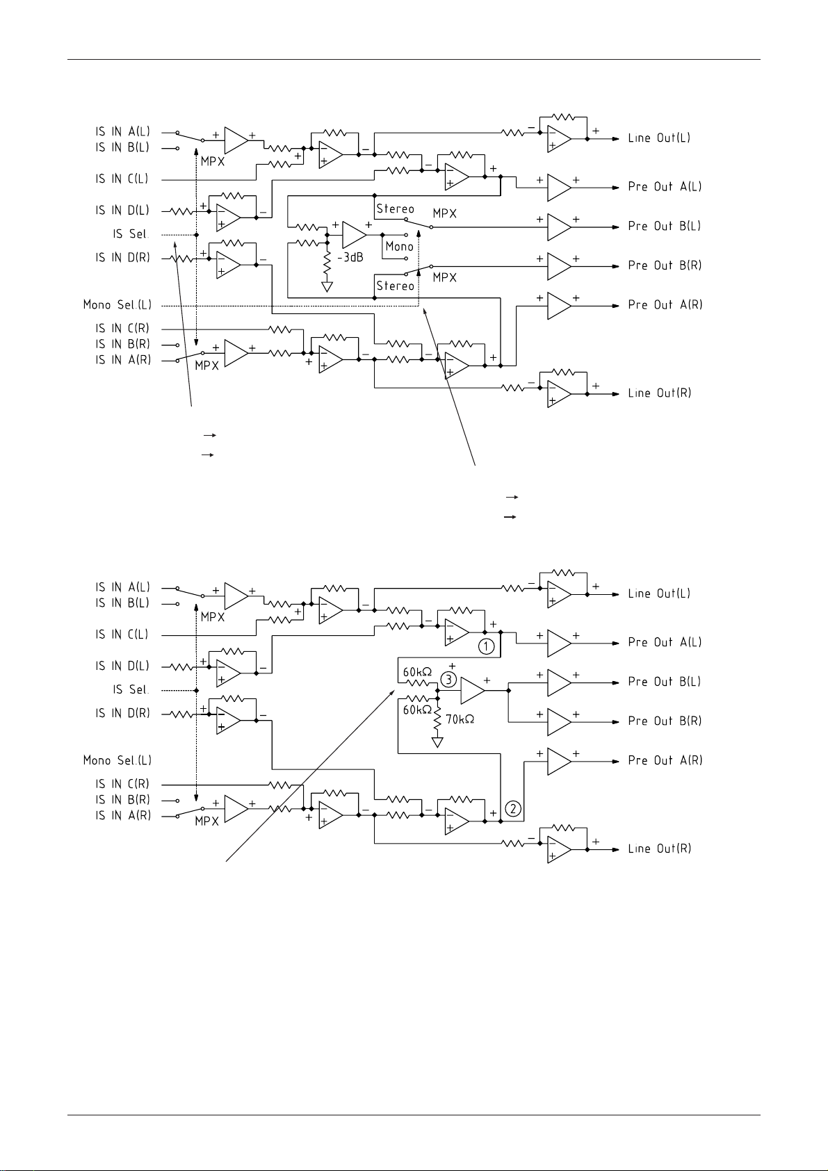
IS Sel. Pin and Mono Sel. (L) Pin Selection
Selects either IS IN A (R) or IS IN B (L).
IS SEL. H A
L B
Audio MM1407
Selects either Pre Out B (L), (R) Stereo/Monaural.
Mono Sel. (L) H Stereo
L Monaural
Figure B. Mono Sel. (L) Pin Pre Out B (L) (R) Signal Route during Mono Selection
The signal route when Mono Sel. (L) pin mono is selected is: point 1 L-ch signal
is lowered 9dB and this signal is added at point 3 to point 2 R-ch signal lowered
9dB.
This level is output to Pre Out B (L), (R).
 Loading...