

MITSMI MM1376 Datasheet
MITSUMI
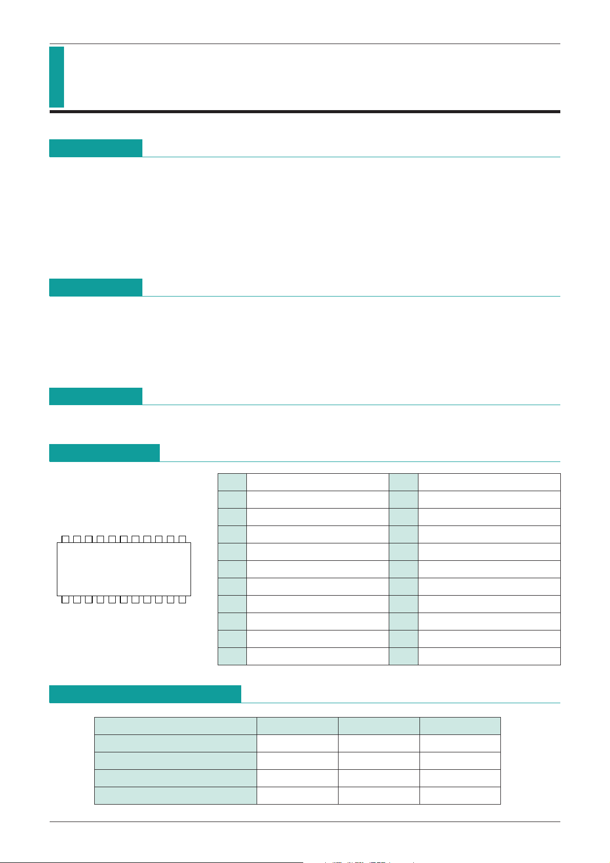
SOP-22
136924587
10 11
22 18 1521 19 17 16 1420 1213
IC for Headphone Stereos MM1376
IC for Headphone Stereos
Monolithic IC MM1376
Outline
This IC was developed for use in 3V headphone stereos, and combines all the basic audio circuitry for
headphone stereos on a single chip.
Recently hearing impairment caused by the high volumes of headphone stereos has become a problem, and
there has been strong demand for functions for limiting loud volumes in the sets themselves. This IC
incorporates an ALC circuit and has functions to hold the output from the headphone to a fixed level; it also
eliminates the ordinary electronic governor circuit in order to accommodate trends toward thinner sets, as
seen in the adoption of BSL motors.
Package
1. Configuration: Pre-and power amps, ALC circuit
2. Internal tape selector: A selector switch allows the user to select between normal and metal tapes.
3. Internal OCL circuit: No need for large-capacitance output capacitor
4. Preamp off function: Preamp alone can be turned off for connection to radio etc.
5. MM1376CF amp gain takes Dolby noise reduction into account
Package
SOP-22
Pin Assignment
1 COM1 12 Power output
2 Preamp non-inverted input 13 V
3 Preamp inverted input 14 Ripple filter
4 Metal switching output 15 Preamp off
5 Preamp output 16 Tape selector
6 Power input 17 Power input
7 Rectifier pin 18 Preamp output
8
9 Power output 20 Preamp inverted input
10 COM2 21 Preamp non-inverted input
11 GND1 22 GND2
ALC control
19 Metal switching output
CC
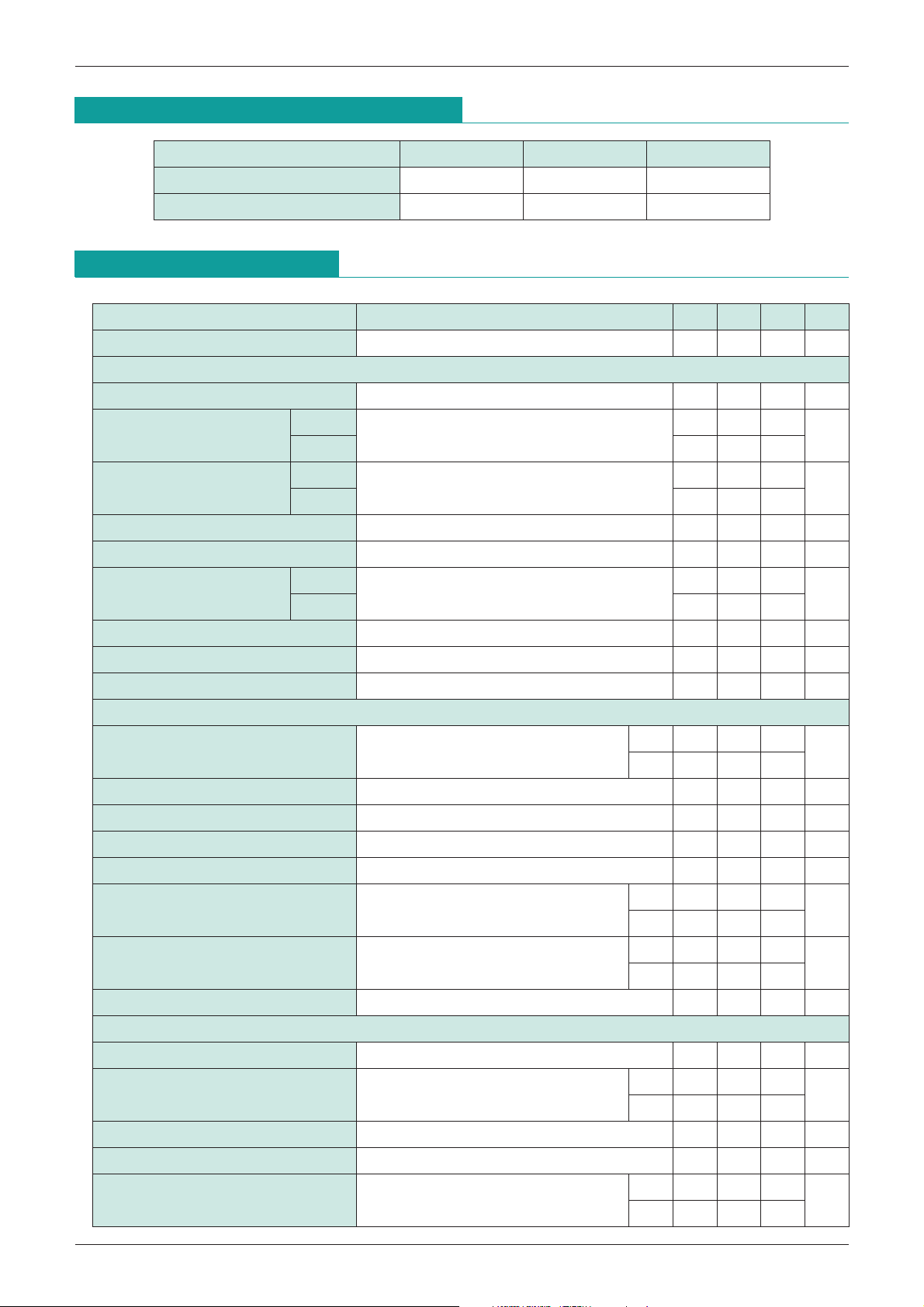
Absolute Maximum Ratings
Item Symbol Ratings Units
Operating temperature T
Storage temperature T
Power supply current V
Power consumption Pd 350 mW
OPR
STG
CC
-
10~+65
-
40~+125
-
0.3~+7.5 V
°
C
°
C
MITSUMI
Recommended Operating Conditions
Item Symbol Ratings Units
Operating temperature T
OPR
IC for Headphone Stereos MM1376
-
10~65
°
C
Operating voltage V
Electrical Characteristics
(Except where noted otherwise, Ta=25°C, VCC=3V, f=1kHz, R
Item Measurement conditions Min. Typ. Max. Units
Consumption current V
Preamp unit
Open-circuit gain 72 dB
Normal
Closed-circuit gain I
Metal 29.5 32 34.5
Normal
Closed-circuit gain II
Metal 23 25.5 28
Maximum output voltage THD=10% 0.30 0.45 Vrms
Total harmonic distortion ratio V
Normal
Output noise voltage
Metal 20 45 100
Crosstalk between channels Rg=2.2kΩ, V
OPR 2.0~5.0 V
IN=0V 6 14 22 mA
Vo=-10dBm, f=1kHz
-
10dBm, f=5kHz
Vo=
OUT=
-
10dBm 0.05 0.5 %
Rg=2.2k, BPF (400~30kHz)
OUT=
-
10dBm 50 70 dB
L
1=10kΩ, RL2=16Ω)
31 33.5 36
28 30.5 33
30 75 150
dB
dB
µVrms
Ripple rejection
VCC=3V, VR=-20dBm, f
Output voltage with preamp off V
ALC (off) + power amp
Voltage gain P
Voltage gain difference between channels
Maximum output current THD=10%, R
Total harmonic distortion ratio P
Crosstalk between channels P
Output noise voltage Rg=0Ω, BPF (400~30kHz)
V
CC=3V, VR=
Ripple rejection
R=100Hz, Rg=0Ω DF 35 40
f
Input resistance 19 24 29 kΩ
ALC (on) + power amp
Power amp output voltage V
ALC initiation input voltage
R
=100Hz Rg=2.2kΩ
IN=100mVrms, Pre off
45 55 dB
-
80-60 dBm
CF 24 26 28
OUT=5mW
DF 30 32 34
-
20 2dB
L=16Ω 30 50 mW
OUT=5mW 0.5 1.5 %
OUT=5mW 35 45 dB
CF 85 200
DF 135 250
-
20dBm CF 35 45
IN=
-
40dBm
CF
DF
-
34-30-26 dBm
-
56
-
62
dB
µVrms
dB
dBm
ALC width
Input width for output from start of up to +4dB
ALC total harmonic distortion V
Noise of preamp+power amp+ALC
Rg=2.2kΩ (Pre amp), Noise of preamp+power amp
30 40 dB
IN=
-
40dBm 0.5 1.5 %
CF 1.5 6
DF 2.8 6
mVrms
 Loading...