

MITSMI MM1333 Datasheet
MITSUMI
Control for Lithium Ion Battery Charging (one cell) MM1333
Control for Lithium Ion Battery Charging (one cell)
Monolithic IC MM1333
Outline
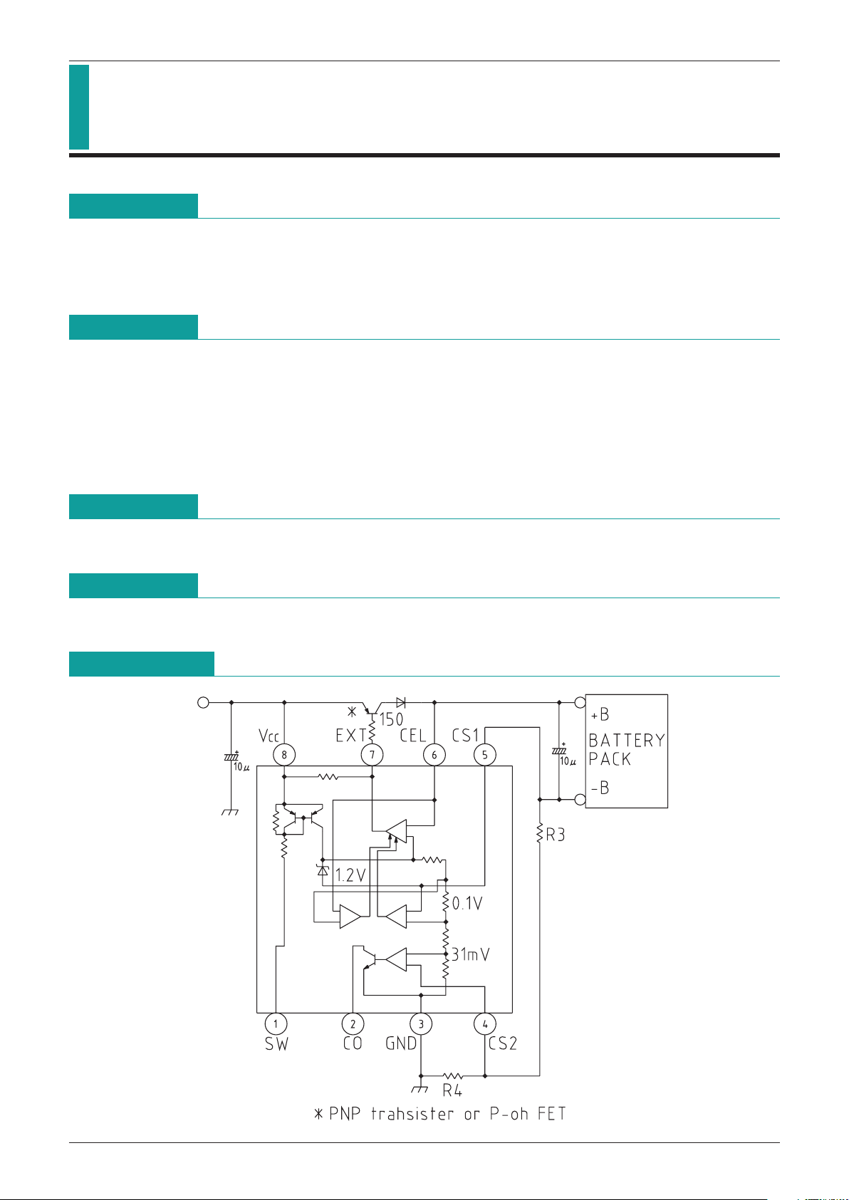
This IC was developed for use in charging lithium ion batteries. A power transistor or P-MOS FET is mounted
externally to control charging. This IC is for use with a single cell only, and provides precise control of the
charging voltage ; the charging current can be set through an external resistance. In addition to the functions
of the MM1332, it incorporates a comparator for full-charge detection.
Features
1. Output voltage (Ta=25°C) 4.100V±35mV
2. Output voltage (Ta=
-
20°C~+70°C) 4.100V±50mV
3. Constant-current output Current limit 100mV±10mV
Constant current value = current limit/external resistance
4. Low-voltage (LV) detection function 2.00V±100mV
5. Full-charge detection function Detection voltage 31mV±5mV
Package
SOP-8C
Applications
1. Lithium ion battery chargers
MITSUMI
Block Diagram
MITSUMI
Control for Lithium Ion Battery Charging (one cell) MM1333
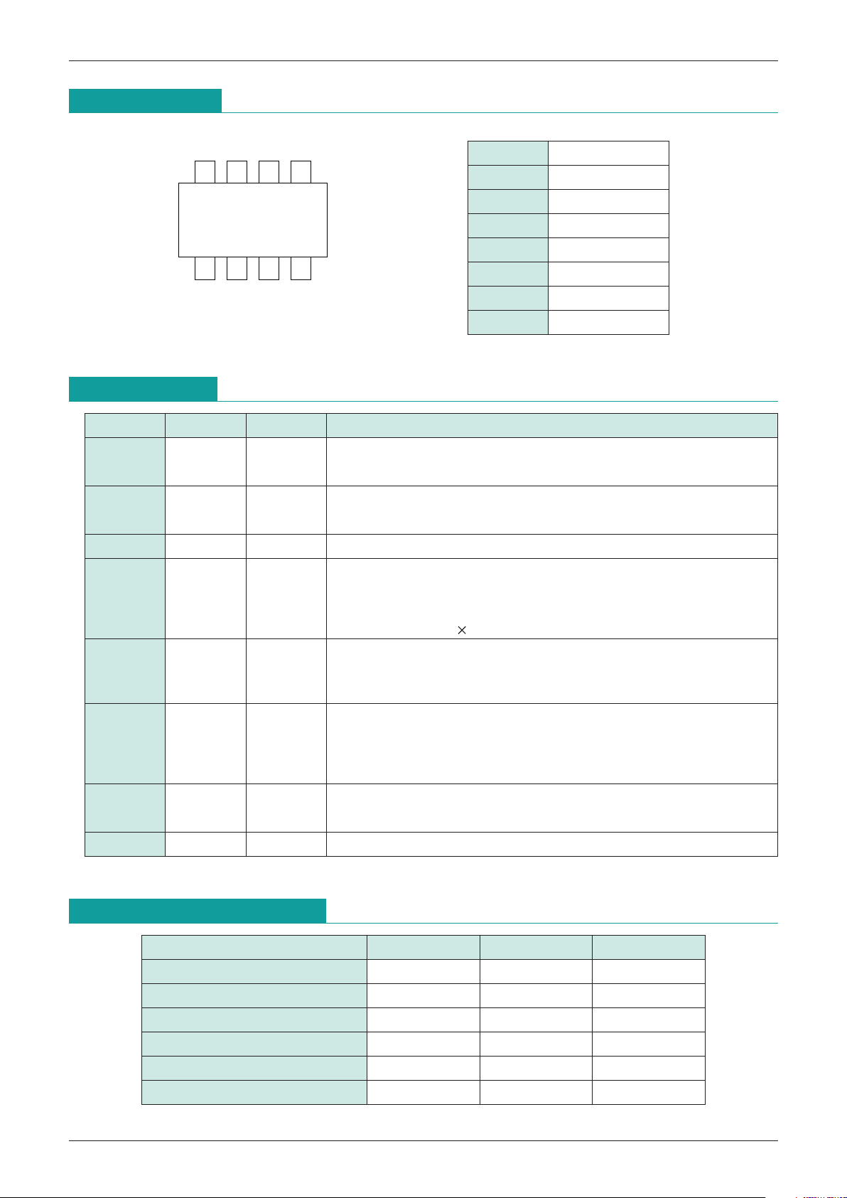
Pin Assignment
Pin Description
Values given are standard
1432
8567
SOP-8C
1 SW
2 CO
3 GND
4 CS2
5 CS1
6 CEL
7 EXT
8 V
CC
Pin no. Pin name
Input/output
Function
1 SW Input
Input pin for on/off control
SW=V
CC : off, SW=GND : on
Pulled up to V
CC, so turned off when open
Full-charge signal output pin
While charging : Open collector output NPN transistor is off
At full charge : Open collector output NPN transistor is on
2 CO output
GROUND pin
3 GND Input
Full charge detection pin
The current is detected through the voltage drop across an external
resistance, to control the full-charge signal.
The ratio of the charge current set by CS1 and the current at full-charge signal
output is (VIC)/(0.1 V R4/(R3+R4))
4 CS2 Input
Current detection pin
The current is detected through the voltage drop across an external
resistance, to maintain a constant current. The current value can be set using
0.1 V/(R3+R4).
5 CS1 Input
6 CEL Input
Battery voltage input pin
The battery voltage is detected and used to maintain the voltage at the
prescribed value.
A low-voltage detection circuit is also present, and charging is forbidden when
the battery voltage is less than 2V.
Constant-voltage circuit output pin
The base of an external PNP transistor or gate of a P-ch FET is controlled in
constant-voltage charging.
7 EXT Output
8 V
CC Input
Power supply input pin
Absolute Maximun Ratings
(Ta=25°C)
Item Symbol Ratings Units
Storage temperature T
STG
-
40~+125 °C
Operating temperature T
OPR
-
20~+70 °C
Power supply voltage V
CC max.
-
0.3~+13 V
Output voltage V
O max.
-
0.3~VCC V
SW input voltage V
SW
-
0.3~VCC+0.3 V
Allowable loss Pd 300 mW

MITSUMI
Control for Lithium Ion Battery Charging (one cell) MM1333
Recommended Operating Conditions
Electrical Characteristics
(Except where noted otherwise, Ta=25°C, VCC=5V, SW2, 4, 6, 7 : A)
MITSUMI
Item Symbol Ratings Units
Operating temperature T
OPR
-
20~+70 °C
Operating voltage V
OPR +5~+12 V
Item Symbol Measurement conditions Min. Typ. Max. Units
Consumption current 1 I
CC1 VSW=0V (Charge : ON) 300 400 µA
Consumption current 2 I
CC2 VSW=0V (Charge : ON) 1.1 1.6 mA
Consumption current 3 I
CC3 VSW=VCC (Charge : OFF) 2 4 µA
Output voltage 1 V
O1 Ta=25°C 4.065 4.100 4.135 V
Output voltage 2 V
O2 Ta=0~+40°C 4.050 4.100 4.150 V
Output voltage temperature drift V
O Ta=
-
20~+70°C ±0.25
mV
°C
Current limit V
CL 90 100 110 mV
CEL-CS leakage current I
CEL 1µA
SW input current I
SW 20 µA
SW input voltage
V
L Charge : ON
-
0.3 2.0 V
V
H Charge : OFF
VCC-
1.0 VCC+0.3
V
Low-voltage detection voltage L
V 1.90 2.00 2.10 V
EXT pin input voltage I
S 10 20 mA
EXT pin output voltage V
EXT No load 0.3
VCC-
0.3
V
Full-charge detection voltage V
IC 26 31 36 mV
Full-charge detection output L V
COL ISINK=0.3mA 0.2 0.4 V
Full-charge detection
output leakage current
I
CO 1µA
 Loading...