

MITSMI MM1304XJ Datasheet
MITSUMI
Variable Gain Amplifier (built-in Y LPF, C BPF) MM1304
Variable Gain Amplifier (built-in Y LPF, C BPF)
Monolithic IC MM1304
Outline
This IC is a variable gain amp for video with built-in luminance low pass filter and chroma band pass filter. It
was developed as a post-filter for D/A converter latter position stage.
The sampling frequencies for the D/A converter are assumed to be 14.3MHz for chroma and 14.3MHz and
9.5MHz for luminance.
Features
1. Luminance LPF cutoff frequency can be selected and set at 5.4MHz and 4.4MHz. When set at 5.4MHz, use
in models that support S, and in normal models when set at 4.4MHz.
2. Chroma BPF center frequency can be selected and set at 3.58MHz (NTSC) and 4.4MHz (PAL).
3. Luminance variable gain range
-
6dB~+6dB
Chroma variable gain range
-
3dB~+9dB and ~1dB~13dB
4. Operating power supply voltage 4.5V~5.5V
5. Luminance S/N (unweight) 10kHz~4.2MHz : 47dB typ.
Package
SSOP-16A (MM1304XJ)
Applications
1. VCR with camera
2. Other video equipment
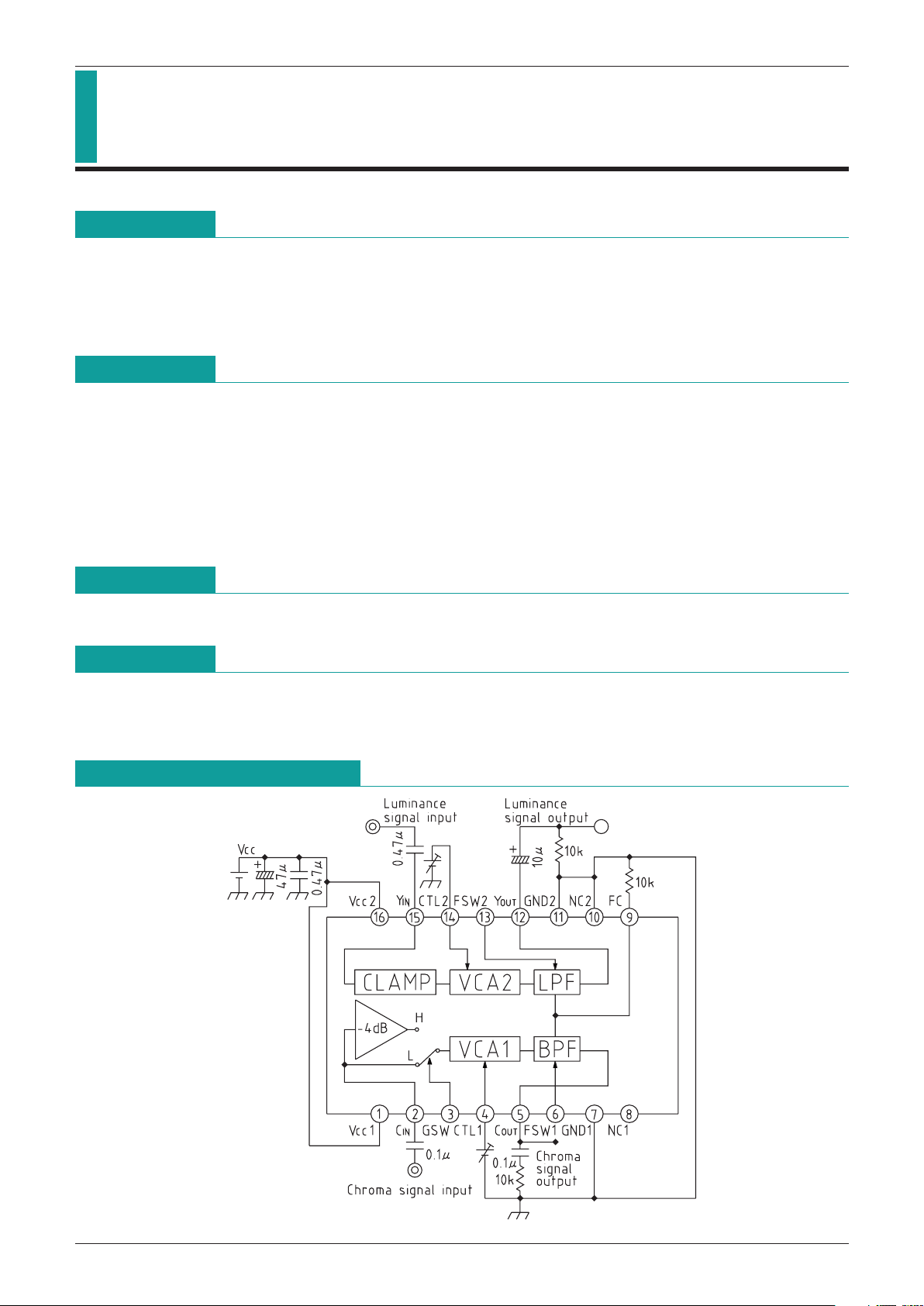
Equivalent Circuit Diagram

MITSUMI
Variable Gain Amplifier (built-in Y LPF, C BPF) MM1304
Pin Description
Pin no. Pin name Equivalent Circuit Diagram Function
1 VCC1
2 C
IN
C power supply pin
Chroma signal input.
3 GSW
C gain switching pin.
Set at 7dB standard for low, and 3dB standard
for high.
4 CTL1
C gain control pin.
5 COUT
Chroma signal output pin.
6 FSW1
C BPF frequency switching pin.
Set at 3.58MHz BPF for high, and 4.43MHz
BPF for low.
7 GND1
C GND
8 NC1
NC pin
 Loading...