

MITSMI MM1301FW, MM1301CW, MM1301AW, MM1301GW, MM1301HW Datasheet
...
MITSUMI
Protection of Lithium Ion Batteries (one cell) MM1301
Protection of Lithium Ion Batteries (one cell)
Monolithic IC MM1301
Outline
This IC provides protection for the MM1291 series of compact, high-precision type lithium ion batteries which
have been in use for some time. Precision of ±30mV is guaranteed between 0°C and +50°C, and this IC can
be used in applications where precision is crucial.
Features
1 Overcharge detection voltage Ta=0~+50°C VCEL±30mV
2 Overcharge detection delay time C
TD=0.082µF 1.0S typ.
3 Current consumption (normal operation V
CEL=3.5V) 10µA typ.
4 Current consumption (overdischarge operation V
CEL=1.9V) 0.7µA typ.
5 Overcurrent cancel conditions Load removed : Load of 5MΩ or greater across battery pack terminals
Package
VSOP-8A
Applications
Lithium ion battery pack (for battery protection)
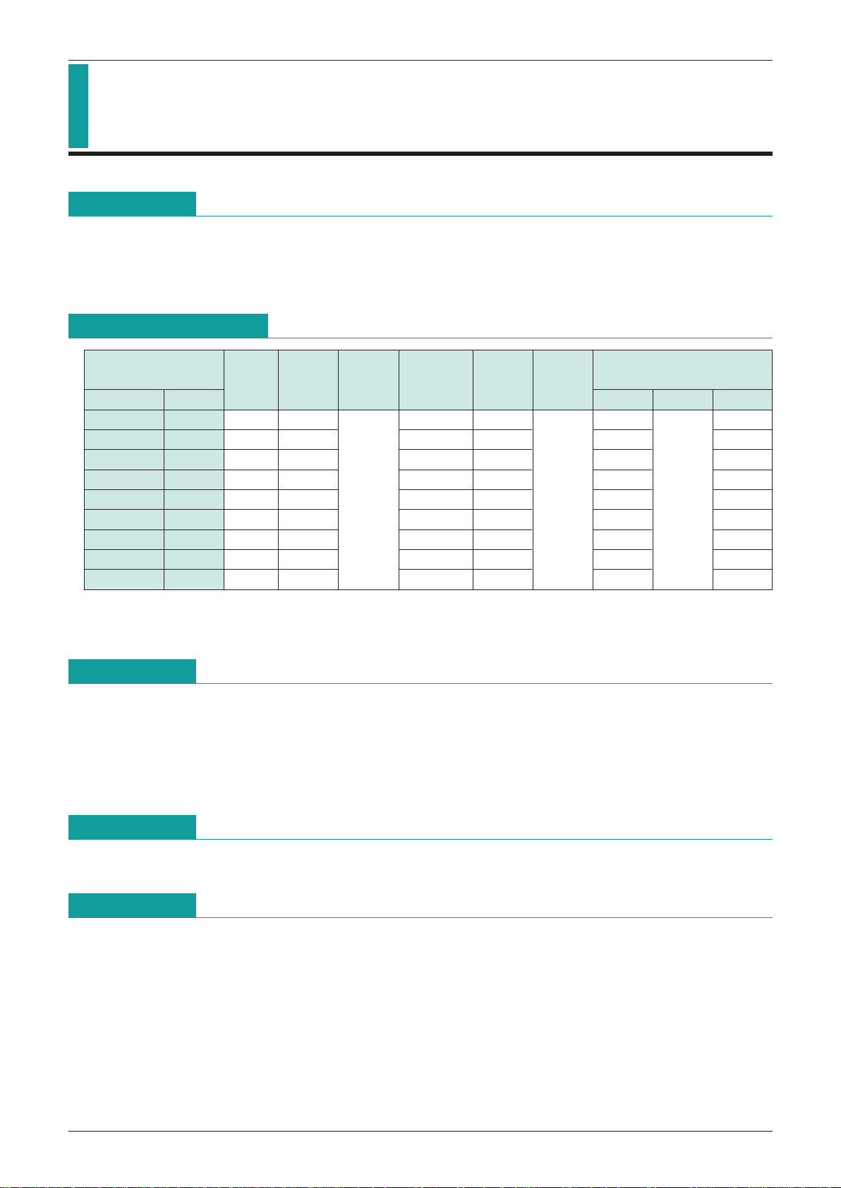
1-Cell Protection ICs
Package
Overcharge
Overdischarge
Release Overcurrent detection
detection
Hysteresis
Dead time
detection voltage
Delay
SOP-8 VSOP-8
voltage
Overcurrent Detec time shot-mode
MM1301 AW 4.27V 200mV 2.3V 2.9V 100mV 0.9V
BW 4.17V 100mV 2.3V 2.9V 100mV 0.9V
CW 4.18V 100mV 2.3V 2.9V 125mV 0.45V
DW 4.28V 220mV 2.3V 2.9V 50mV 0.45V
EF 4.20V 100mV 2.3V 2.9V 125mV 0.45V
FW 4.28V 100mV 2.3V 2.9V 50mV 0.45V
GW 4.18V 220mV 2.3V 2.9V 125mV 0.45V
HW 4.35V 220mV 2.3V 2.9V 50mV 0.45V
JW 4.20V 220mV 2.3V 2.9V 125mV 0.45V
at
Ctd=
0.082µF
min. 0.5S
typ. 1S
max. 1.5S
min. 5mS
typ. 10mS
max. 15mS
min. 5mS
typ. 10mS
max. 15mS
Note : Under open-load conditions, returns to normal mode from overcurrent mode.
(For MM1291A to G, J, M, 5MΩ or higher; for MM1291H, K, 50MΩ or higher)
MITSUMI
Protection of Lithium Ion Batteries (one cell) MM1301
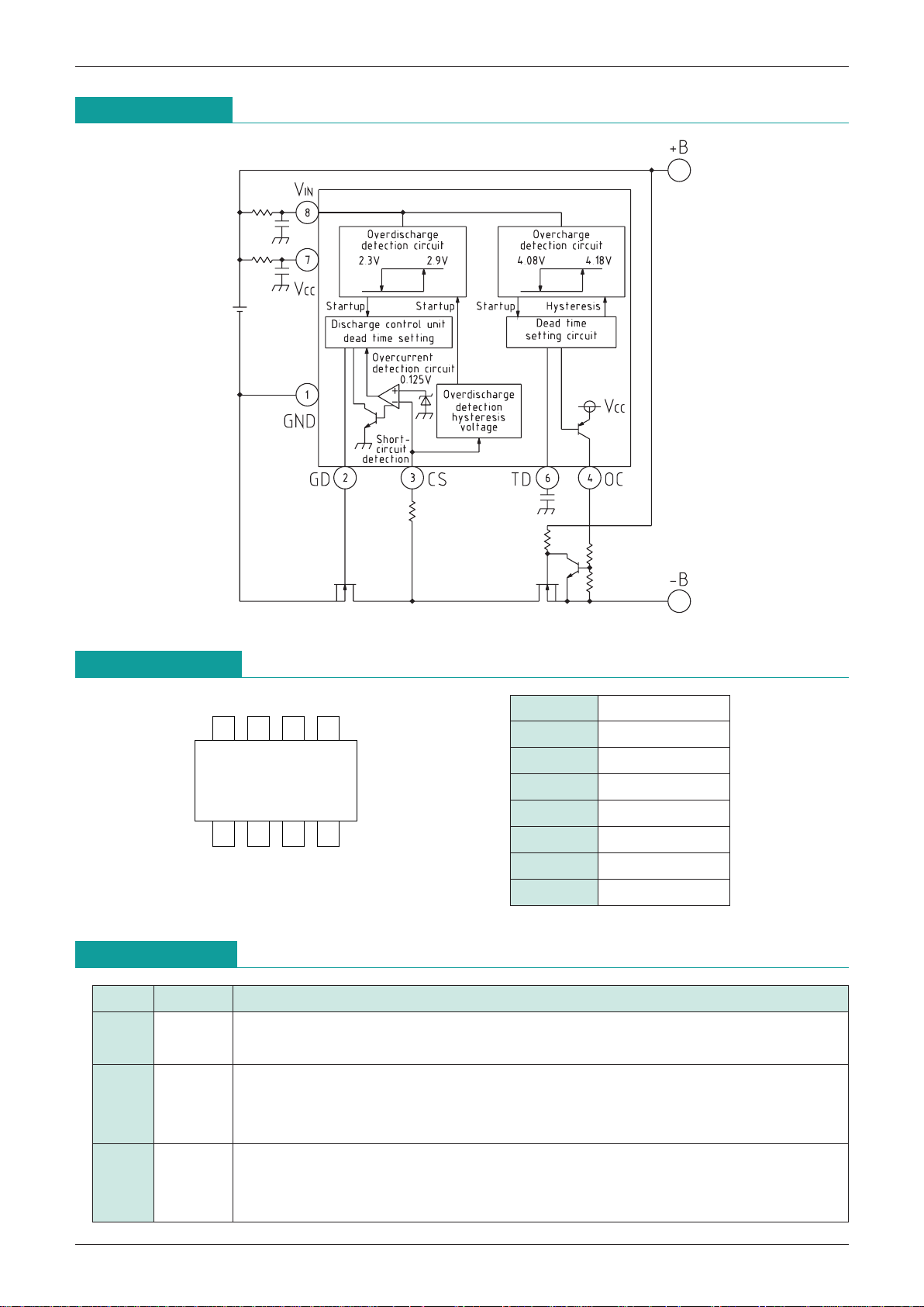
Pin Assignment
Pin Description
1432
8567
VSOP-8A
1 GND
2 GD
3 CS
4 OC
5 N.C
6 TD
7 V
CC
8 VIN
Pin No.
Pin name Function
1 GND
Negative power supply pin
Also serves as voltage detection pin for battery connected between V
IN and GND
Gate connection pin for discharge-control FET (N-ch)
2 GD Turns the gate off in overdischarge mode and overcurrent mode. Gate is turned on in
overcharge and normal modes.
Overcurrent detection input pin
3 CS Discharge current detected by connection to drain pin of discharge-control FET.
Discharge current = (CS-GND voltage)/(FET turn-on resistance)
Block Diagram
 Loading...