

MITSMI MM1096BS, MM1096BD, MM1096AD, MM1096AF, MM1096BF Datasheet
...
MITSUMI
1432
8567
DIP-8B/SOP-8C
SIP-8A
13572468
System Reset (with built-in watchdog timer) MM1096
System Reset (with built-in watchdog timer)
Monolithic IC MM1096
Outline
This IC functions in a variety of CPU systems and other logic systems to generate a reset signal and reset the
system accurately during momentary interruption or lowering of power supply voltage.
It also has a built-in watchdog timer for operation diagnosis. This prevents the system from running wild by
generating an intermittent reset pulse during system mis-operation.
Features
1. Built-in watchdog timer
2. Low minimum operating voltage 130µA typ.
3. Low operating limit voltage V
4. Watchdog stop function (RCT pin)
5. Long clock monitoring time
T
PR (POWER ON) : TWD (clock monitoring)=1 : 5
6. Few external parts
CC=0.8V
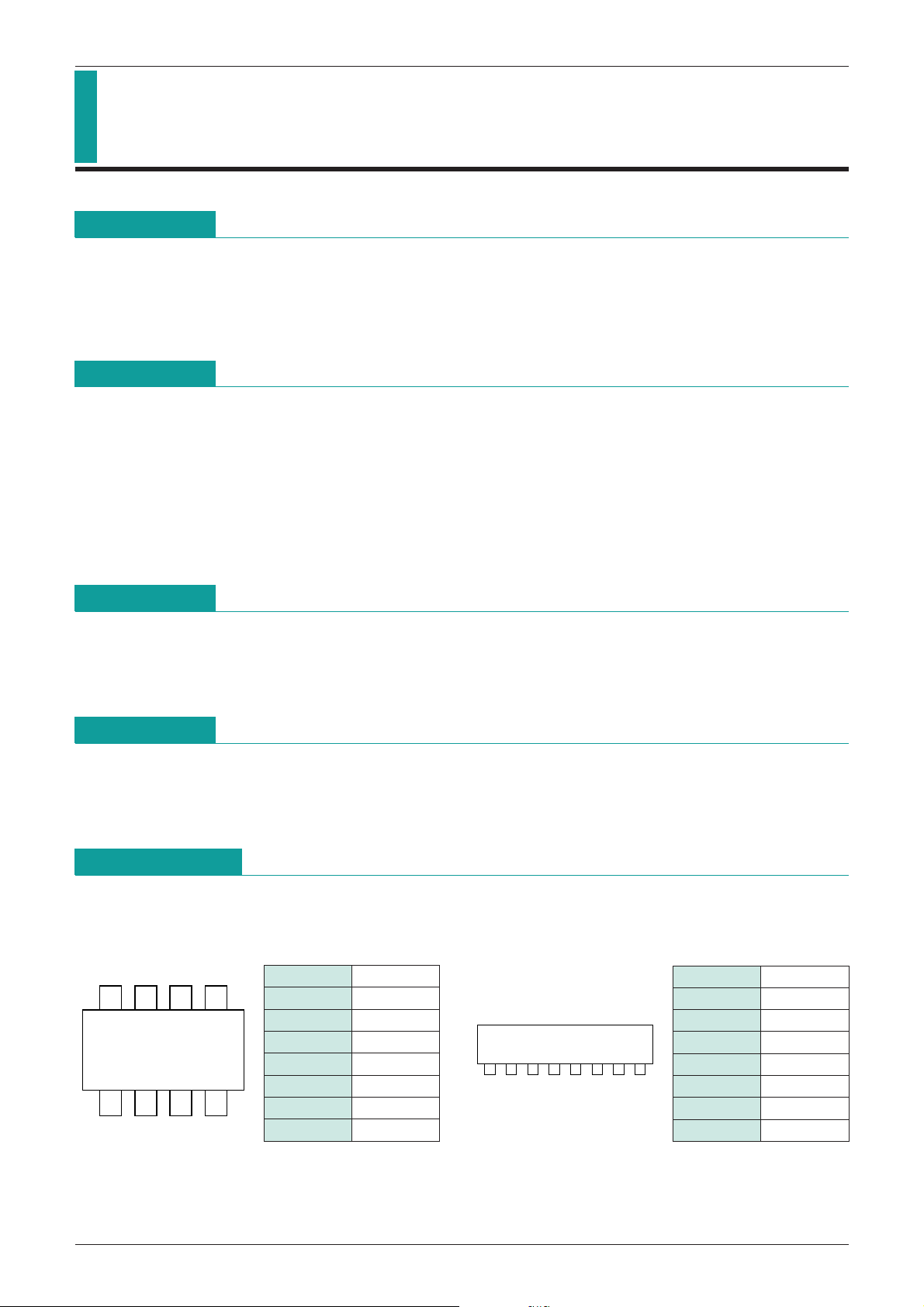
Package
DIP-8B (MM1096AD, MM1096BD)
SOP-8C (MM1096AF, MM1096BF)
SIP-8A (MM1096AS, MM1096BS)
Applications
1. Reset circuits in microcomputers, CPUs and MPUs
2. Logic circuit reset circuits
3. Microcomputer system monitoring, etc.
Pin Assignment
1 TC
2 NC
3 CK
4 GND
5 V
6 RCT
7 V
8 RESET
CC
S
------------------------------------------------------
1 TC
2 NC
3 CK
4 GND
5 V
6 RCT
7 V
8 RESET
CC
S
------------------------------------------------------
MITSUMI
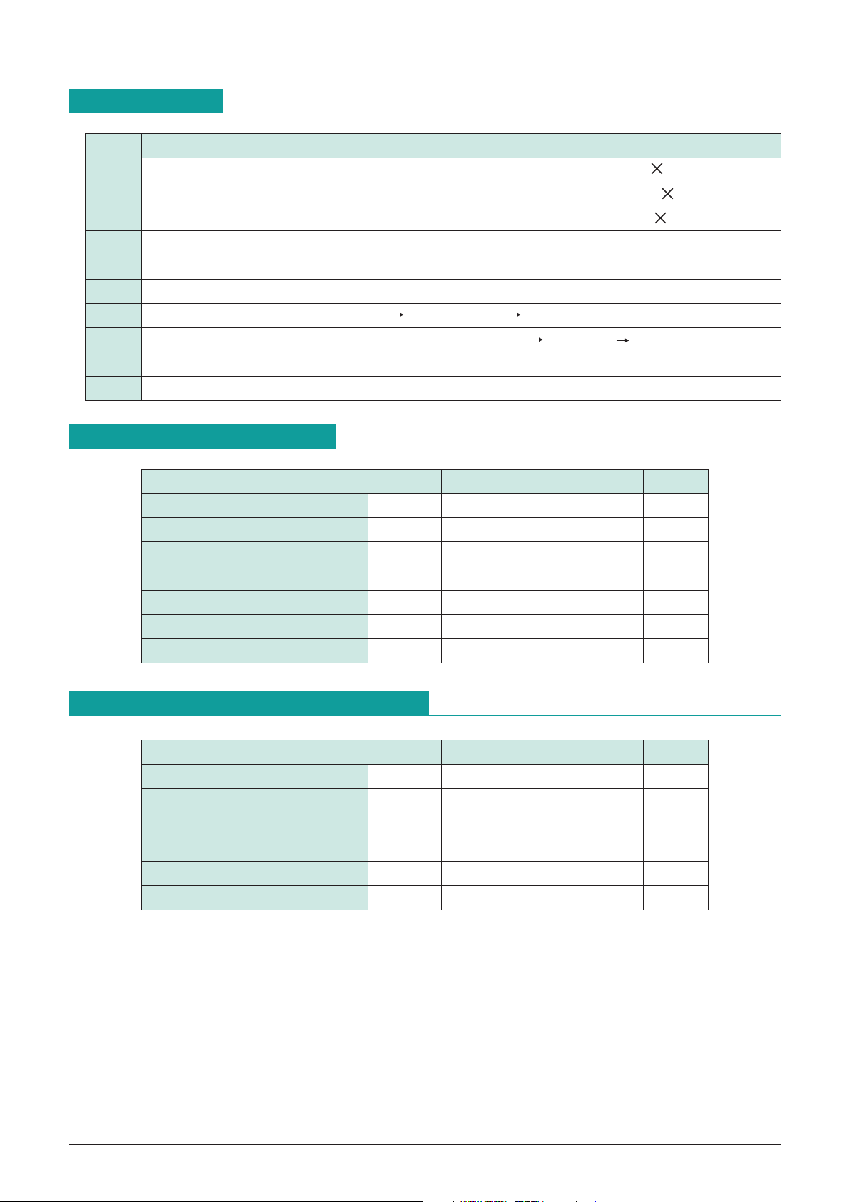
Pin Description
System Reset (with built-in watchdog timer) MM1096
Pin No.
Pin name
TWD, TWR, TPR variable pins. TPR (mS) = 500 CT (µF)
1 TC
(T
WD, TWR and TPR times are determined TWD (mS) = 2500 CT (µF)
by the external capacitor.) T
2 N.C
3 CK
4 GND
5 V
6 RCT
7 V
---------------------------------------------------------------
8
RESET
Clock input pin, inputs clock from logic system
GND pin
CC
Voltage detection MM1096A 3.2V, MM1096B 4.2V
Watchdog timer stop pin Operation modes : Operation OPEN, Stop connect to GND
S
Detection voltage variable pin
Reset output pin (low output)
Absolute Maximum Ratings
Item Symbol Rating Units
Power supply voltage V
CK pin input voltage V
S pin input voltage VVS
V
Voltage applied to RCT pin V
Voltage applied to RESET
Allowable loss Pd 300 mW
Storage temperature T
----------------------------------------------------
CC max.
CK
RCT
pin VOH
STG
Function
-
-
0.3~VCC+0.3 (
-
0.3~VCC+0.3 (
-
0.3~VCC+0.3 (
-
0.3~VCC+0.3 (
-
WR (mS) = 100 CT (µF)
0.3~+10 V
<
+10) V
=
<
+10) V
=
<
+10) V
=
<
+10) V
=
40~+125
°
C
Recommended Operating Conditions
Item Symbol Rating Units
Power supply voltage V
----------------------------------------------------
RESET
sync current IOL 0~1.0 mA
Clock monitoring time setting T
Clock rise and fall times t
TC pin capacitance C
Operating temperature T
CC +2.2~+7.0 V
WD 0.1~1000 mS
FC, tRC <100 µS
T 0.0002~2 µF
OP
-
25~+75
°
C
MITSUMI
System Reset (with built-in watchdog timer) MM1096
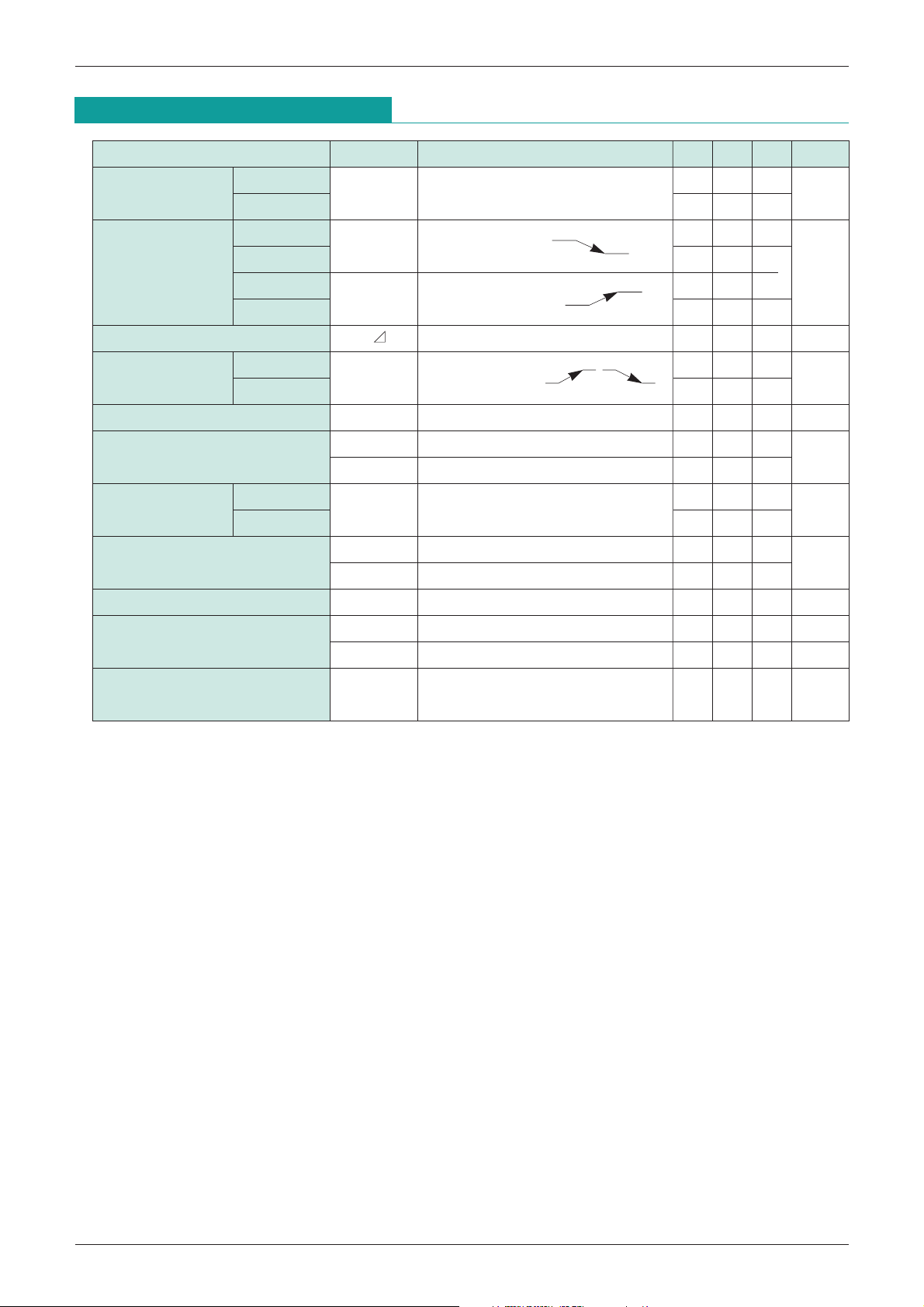
Electrical Characteristics (DC)
Item Symbol Measurement conditions Min. Typ. Max. Units
Consumption current
Detection voltage
Detection voltage temperature coefficient
Hysteresis voltage
CK input threshold V
CK input current
Output voltage MM1096A
(High) MM1096B V
Output voltage (Low)
R output sync current I
MM1096A
CC During watchdog timer operation
I
MM1096B 130 195
MM1096A
V
MM1096B 4.05 4.20 4.35
MM1096A
V
MM1096B 4.15 4.30 4.45
VS/ T ±0.01 %/°C
MM1096A
HYS
V
MM1096B 50 100 150
I
I
V
OL1 I =0.5mA, VS=0V 0.2 0.4
V
V
OL2 I =1.0mA, VS=0V 0.3 0.5
OL V =1.0V, VS=0V 1 2 mA
(Except where noted otherwise, MM1096A : V
CC
=3.6V, Ta=25°C, MM1096B : VCC=5.0V)
100 150
3.10 3.20 3.30
SL
VS=OPEN, VCC
3.15 3.25 3.35
SH
VS=OPEN, VCC
25 50 100
VSH-VSL, VCC
TH 0.8 1.2 2 V
IH A : VCK=3.6V, B : VCK=5.0V 0 1
IL VCK=0V
----------------------------------------------------
RESET
OH
I =1µA 3.0 3.4
S=OPEN 4.0 4.5
----------------------------------------------------
RESET
----------------------------------------------------
RESET
----------------------------------------------------
RESET
-
12-6
mV
-
2
µA
V
µA
V
V
T charge current
C
Minimum operating power
supply voltage to ensure RESET
---------------------------------------------------
I
CT1
I
CT2
VCCL 0.8 1.0 V
VTC=1.0V during watchdog timer operation-0.28-0.48-0.96 µA
VTC=1.0V during power ON reset operation-1.60-2.40-4.80 µA
----------------------------------------------------
RESET
V =0.4V
----------------------------------------------------
RESET
I =0.1mA
 Loading...