

MITS altair 680b Assembly Manual
altair
68Ob
II.
MAIN
PC
BOARD
ASSEMBLY
IC Socket and IC
Installation
Capac'i
tor
Instal
I ati on
Resistor Installation
Transi
stor Instal
I ati on
Diode
and Crystal
Installation
Voltage
Regulator
Installation
Bri dge Rect
j
f i er Instal
I
at'ion
Connector Instal
I
ati on
Input/0utput
Confi
gurations
Jumper
Wire
Connections
Paper
Tape Reader
Control
M0S
IC Installation
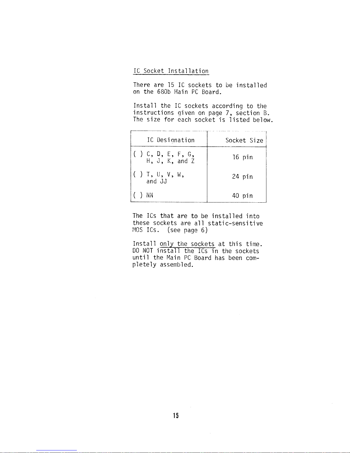
IC
Socket Instal
I
ati on
There are
15
on the 6B0b
Instal
I the
i nstructi
ons
The
s'ize
for
IC
sockets
to
be installed
t,lai
n PC
Board.
IC
sockets
according
to
the
qjven
on
page
7, section B.
each
socket is
listed below.
The
ICs
that
are
to
be
'installed 'into
these
sockets
are
al I stati
c-sens'it'ive
I40S
I Cs .
(see
page
6
)
Install
onl.v
the sockets
at this
t'ime.
D0 NOT install
the ICs in
the
sockets
unt'il the
Main
PC
Board
has been
com-
pletely
assembled.
15
IC Desi
qnat'ion
(
)
c,
D,
Eo
F,
G,
H,
J, K,
and
Z
O
T, U,
V, l^J,
and
JJ
(
)
ilN
16
pin
24
pin
40
pin

iC
Installation
There
are 3l
ICs
to
be
jnstalled
(with-
out sockets)
onto tire
6B0b
Majn
PC
Board.
Instal
I
these
ICs
accordi
ng
to the
'in-
structions on
page
7,
section
A.
The
correct
part
numbers for the
ICs
are
listed below.
Part
I'lumber
il
A,
B,
X, HH, MM, VV,
()
()
()
()
()
()
()
()
()
()
()
and
7Z
L
(Baudot
only)*
M
ll
and
P
R, S, CC,
and
PP
Y
AA, KK, LL, and UU
BB
DD,
EE, and
FF
GG and SS
TT
RR, I,l'',l,
XX,
and
YY
741S04
74L574
74LSl
0
74LS0l
4050**
741S00
741S30
4449**
74L520
74L502
741S7 3
7 4367
(or
BT97)
*i'l0TE:
Install IC L 0iiLY if a
Baudot termi
naFs
to
be
i
nterfaced
to the
680b.
**Stat'i
c-Sensi
ti ve
MOS ICs .
See
page
6 before installing.
l6
1u
l---l=j__J"
D
Y
r---l
*:[--lo,l_----]
,[--1n
"Io"F=
-:_
ffi8p"
,F",f
I
.I___JU
,l_____l
+
l0
,l___lU
ffi I
f--l0 |
r--_ln
AilrlililAi- ll
'H;
,=]
=:
i/t'ltlt]tlvtf=E
.Lr
:E!
HF+
Ti=
c
l1
-:F--lo
oI+
ol I
*.-
F----lu
'4"U
*i___J
tl
I
tl
nl-r rl
nll
"*------)
-d
-
;l
|
.Lr
rn
qfl---t
.-
F=lFoFEa
ll
q'j---l+*J3Eo[],f:,i:
fl- il
I
U -.-----\- |
+
fttJtl
-1
- 1-----_j+ |
I
I - | I
G
6--l:
,1,
-L--_ts
|
n----/-
i:=a lI-T=-l I
,1. il | | il I
+
| I
rA
-*--ri-u-nll
I lll
lr---rll
ilI il|
lll ll
'll
| |L-
Jt-l ll I
rnrr rl
ll lll-
i+-r+
ll
Llll
ll ll lul
11
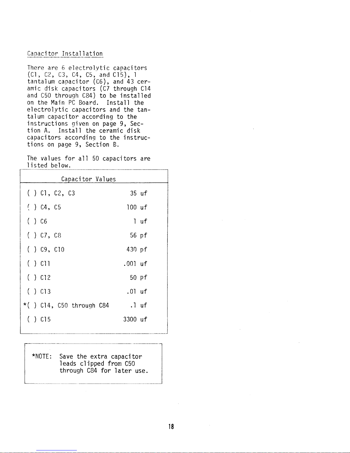
Capaci
tor
Instal
I ati on
There
are 6 electrolvtic
capacitors
(cl,
c2,
c3, c4,
c5, and clb), I
tantalum
capacitor
(C6),
and 43 cer-
amic
disk
capacitors
(C7
through
C14
and
C50
throuqh CB4)
to
be installed
on
the Main PC
Board. Install
the
electrolytic
capacitors and
the tan-
talum
capacitor according
to the
instructions
given
on
page
9, Sec-
tion
A. Install
the ceramic disk
capacitors
accordinq
to the
instruc-
tions
on
page
9, Section
B.
The
values for
all 50 capacitors are
I isted
below.
i
tor
Val
ues
()ct,c2,
()c4,c5
(
)
co
()c7,cB
(
)
cg, cto
()cil
LJ
35 uf
.l00
uf
luf
56
pf
430
.001
50
pf
.0.|
uf
.l
uf
3300
uf
pf
uf
(
)
ct2
(
)
cr3
*(
)
Cl4, C50
throuqh
CB4
(
)
crs
*NOTE:
Save
the
I eads
cl
through
extra
capaci
tor
ipped from
C50
CB4 for
later use.
t8

il!
0
I
0i
0sB
Aql
ll-
3
.----
i
@
b
Cf
E
"E
4f
?W
f
"!
Fru
i
s0F0-
I
-1_r
E^
,rus
AirlrlrlAi
VV! HVY ?
o
I,Wou
Wla
ilon
*:ffiol
.w
W
.w
0r
=F
ll
tl
.Ll
!e
.l
l-t
\l
n
U
0s
o
+J
r(,
(d
4-)
an
L
o
4-)
6
o
(o
(J
0s
,f,
-I
f
Hililil
r+
:
F--l
Ir-tl
l-'
I
-.D
r-------r
I
-rT-.r-
-t----1,
J----a
o
.-<fl-
rl'
rm
ll
L--l
ll
-(I:}-
{>
r9

Res
i s
tor
Ins
ta
I I ati on
Instal
I the
fol I owi nq
on
the
l'lain
PC Board.
structions
listed
on
37
resistors
Use
the
in-
N0TE:
Al'l
of
the
resistors
on
the
Main
PC
Board
are
either
1/4
watt
or 1/2
watt,
except
R21,
which
is
a 2-watt
res.istor.
page
B.
Resistor
Values
and
Color
Codes
I
)
Rl
through R9, Rl5, R30
)
Rl0,
Rll, Rl3, Rl7,
RIB
)
Rr2
)
Rt4
)
Rt6
)
Rl9, R20
)
R2r
)
R22
)
R23,
R2B
)
R24,
R25, R26, R27,
R3l, R32
)
Rze
yel
I ow,
vi ol et
,
red
brown,
black,
orange
orange,
orange, orange
orange,
oranqe, brown
brown, black,
blue
orange,
orange,
red
(2
watt), brown,
gFeer,
black
brown,
b1ack,
red
ye'l
1ow,
viol et,
b1
ack
yel
I ow,
v'io1et,
brown
brown, b1
ack,
brown
4.7K
ohm,
l0K
ohm,
33K ohm,
330
ohm,
10M
ohm,
3.3K
ohm,
15 ohm
1 K
ohm,
47
ohm,
470 ohm,
1 00
ohm,
Res'istor Pack
Instal I ation
After
installing
a1l
37 resistors,
the 4 resistor
packs
(RPl
through
RP4)
must be
installed.
The re-
sistors
within
these
packs
each have
a
value
of
4.7K ohms. Each
pack
has
a small dot
printed
at one
end.
This dot must
correspond with
the
dot
printeE-on
the
PC Board.
Use
the following
instructions
to in-
stall
each
resistor
pack.
l.
Install
the resistor
pack
at
a
perpendicular
angle
to the
silk-screened
side
of the
board.
Make
sure
the
dot
on
the
res i
stor
pack
i
s a1 i
gned
with
the dot
printed
on the
PC
Board.
Tape
the resistor
pack
in
place
and turn the board over. Before solderinq,
check
that
the
resistor
pack
is
still
perpen-
dicular
to the
board.
Carefully
solder
each
pin
of
the
resistor
pack
to the
foil
pattern
on the
back of
the
board.+
Turn
the
board over
aqain and
remove
the
tape.
(
)
RPI
through
RP4 are 4.7K ohm
resistor
packs
2.
?
*N0TE:
The
foil
pattern
on the
solder
mask.
The solder masks
back
of the
board i s
helps
prevent
solder
partially
covered
by
a
bri
dges across
I
ands.
Special
lnsert
Page
RESISTOR
PACK
SUBSTITUTIOi'IS
ALTAIR
6BOb I'IAIN
PC BOARD
Due
to
supply shortages,
your
6B0b
kit
has been
shipped
to
you
wjthout
the four 4.7K
ohm
Resistor
Packs
(npt-np+)
called for
on
page
20
of the Assembly Manual.
Nine
4.7K
ohm,
1/4
watt res'istors
have
been
substituted
for each
pack.
These
substitute
resistors
must be
installed
according
to the djrections
outljned
below.
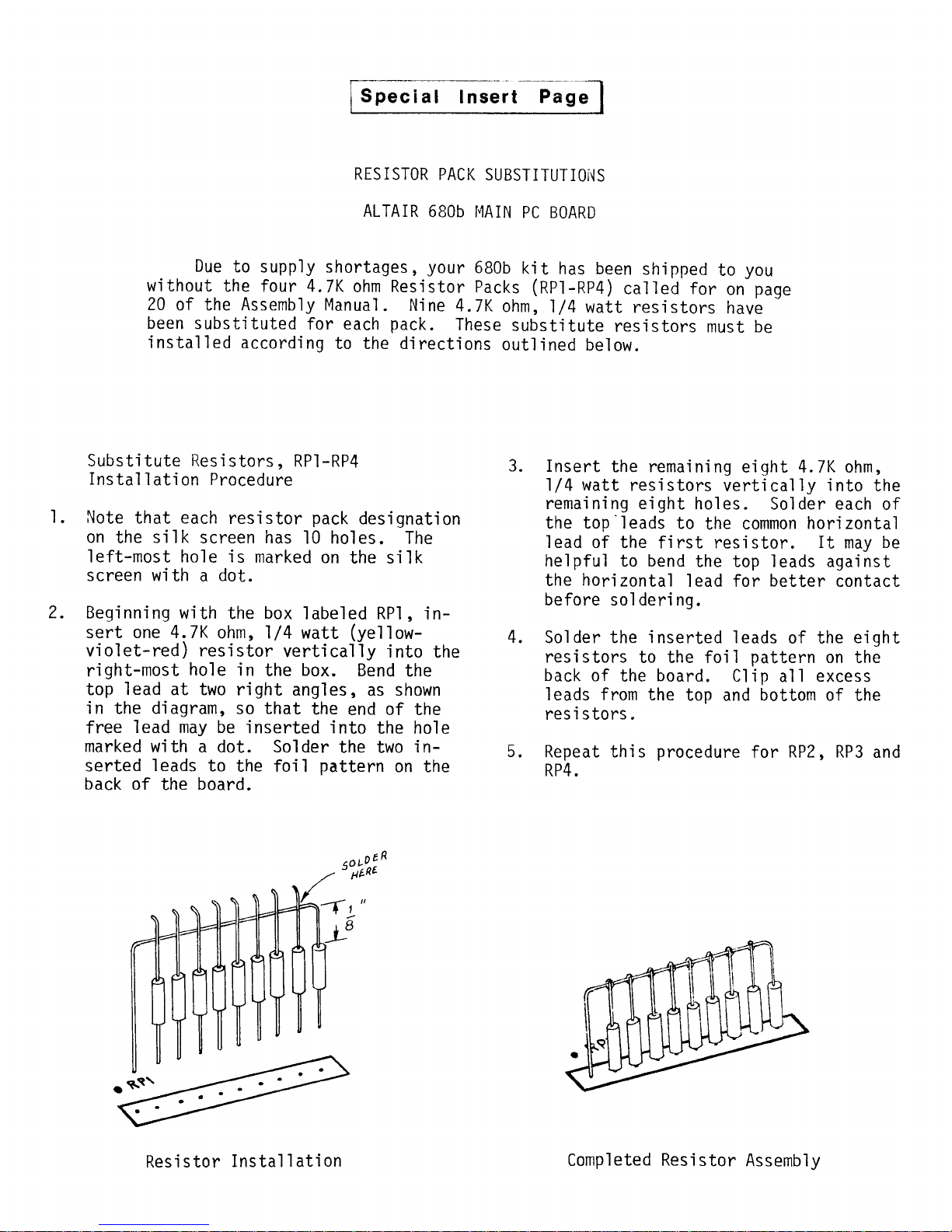
Substi
tute
Resi
stors , RPI
-RP4
Instal
I ati on
Procedure
i"lote
that
each
res'istor
pack
designation
on
the
silk
screen has
l0 holes. The
left-most hole is
marked
on
the silk
screen with a dot.
Beginning
with
the
box
labeled
RP1,
in-
sert one 4.7K
ohm, 1/4 watt
(ye1'low-
vi ol et-red ) resi
stor
verti ca1
'ly
i nto the
right-most
hole
in
the
box.
Bend
the
top
lead
at two
rjght
angles, as shown
jn
the
diagram,
so that
the
end of the
free
lead
may be
inserted into
the hole
marked with
a dot. Solder
the two
in-
serted
leads
to
the foil
pattern
on the
back
of
the
board.
Insert
the remai
n'i ng ei
ght
4. 7K ohm,
l/4
watt
resistors
vertically
into
the
remaining eight
ho1es. Solder each
of
the top'leads
to
the
common
horizontal
lead of the
fjrst resistor.
It
may
be
helpful to bend
the top leads
against
the
horizontal
lead for
better
contact
before so1 deri ng.
Solder the
inserted
leads
of the
eight
resistors
to the foil
pattern
on
the
back
of
the
board.
Clin
all excess
leads from the
torr
and
bottom of
the
res'istors.
Repeat this
procedure
for
RPZ, RP3
and
RP4.
J.
t.
2
A
q
Resi stor
Instal I ati
on
Completed
Resistor
Assembly
 Loading...