

Page 1

ROM BASIC Turnkey Module
User’s Manual
Page 2

!
!
TABLE OF CONTENTS
ABSTRACT................................................................ 1!
SPECIFICATIONS.......................................................... 1!
INSTALLATION............................................................ 2!
THEORY OF OPERATION..................................................... 5!
ASSEMBLY................................................................ 7!
SCHEMATIC DRAWINGS...................................................... 9!
Page 3

1
88-RMB2
User’s Manual
ABSTRACT
The 88-RMB2 (ROM Basic Turnkey Module) provides MITS Extended Cassette
Basic programming language in Read Only Memory (ROM). Basic is located in
the upper 16K of main memory, addresses 48K through 64K (140000 through
177777 octal). This frees up the lower 48K for the user’s Basic programs.
An automatic startup circuit causes the computer to begin executing Basic
at 140000 (octal) when system power is first applied and after a Reset.
In addition to Basic in ROM, the 88-RMB2 has system functions that allow
the 8800b Turnkey Module to be eliminated.
A serial asynchronous input/output port on the 88-RMB2 interfaces the
system console (or any terminal) to the computer. Most standard baud
rates are available, as well as both RS-232 or TTL signal configurations.
The port can interrupt on input or output. The I/O port addresses are
fixed at 020 and 021 (octal).
The 88-RMB2 provides the signals to the Attaché or 8800bt front panel for
the control switches “STOP/RUN” and “START”, and the system indicators,
1) HLT (HALT), 2) I/O (INPUT/OUTPUT), 3) INTE (Computer interrupts
enabled), 4) INT (Interrupt request) and PWR (+5V Power OK).
The 88-RMB2 also provides sense switch input at port address 377 (octal).
SPECIFICATIONS
Firmware......... Extended Cassette Basic in Read-Only Memory (16K bytes)
(8 2K/* ROM IC’s)
ROM Address: 140000 (octal)
Auto-start....... Fixed address: 140000 (octal)
Activation: Power-on or Reset
Serial I/O Port.. Configuration: RS-232 or TTL
Baud Rate: 110, 300, 1200, 4800, 9600
Fixed I/O Address: 020 and 021 (octal)
Sense Switches... Eight data switches read from I/O port 377 (octal)
Power............ 1 amp at +8V
40 mA at ±18V
Physical......... 5” x 10” printed circuit board
1 slot required
Page 4

2
INSTALLATION
Memory Address
The 88-RMB2 has a hardwired auto-start and non-user addressable ROMs.
The auto-start jumps to the ROM at 140000 (octal). The ROM occupies
memory from 140000 (octal) to 177777 (octal). Make sure your machine
contains no other memory between these addresses.
Sense Switches
I/O port 377 (octal) is reserved for sense switches, at SW-2 on the
88-RMB2 board. These switches may be read by software to control I/O
addressing, stop bits, etc. Unless instructed by a software manual,
these switches will normally be set to produce 000 (octal). Set
switches at SW-2 to the right to produce a 0, and to the left to
produce a 1. Software manuals often uses the words “up” and “down”
when specifying sense switch settings. On the 88-RMB2, “up”
corresponds to left on SW-2, and “down” corresponds to right on SW-2.
Software manuals refer to switch positions A8-A15, which correspond to
SW-2 positions 8-15.
Status Connector
J1 is used to provide machine status to external LEDs located on the
Attaché keyboard or 8800bt front panel. J2 is indexed to prevent
installing the cable incorrectly.
J1 Pin Signal Direction Function
1 +5V Out Power for 8800bt front panel
2 -SHLTA Out Low indicates CPU HALT condition
3 -PINTE Out Low indicates interrupts are enabled
4 -IO Out Low indicates Input or Output cycle
5 -PINT Out Low indicates interrupt requested
6 GND Out Ground reference
7 -POC In CPU reset from front panel STOP switch
8 PRDY In Input from front panel STOP/RUN switch
9 KEY - Pin removed for indexing connector
10 N/C - Not connected
Serial Port
J2 is used for the serial port. J1 is indexed to prevent installing
the cable incorrectly.
J2 Pin Signal Level Direction Function
1 -RTS TTL Out Active-low Request to Send
2 N/C - - Not connected
3 N/C - - Not connected
4 RxD Both In Receive Data
5 -DCD Both In Active low Data Carrier Detect
6 -CTS Both In Active low Clear to Send
7 KEY - - Pin removed for indexing
8 GND - - Ground reference
9 -RTS RS-232 Out Active-low Request to Send
10 TxD Both Out Transmit Data
Page 5

3
The 88-RMB2’s serial port is hardwired to ports 20 and 21 (octal). Use
the following table to set up the port for TTL (Use these settings for
the Attaché and the 8800bt).
Signal Direction J2 Pin Jumpers
TxD Out 10 W16 open, W17 jumpered
-RTS Out 1
RxD In 4 W13 open
-CTS In 6 W15 jumpered
-DCD In 5 W14 jumpered
GND - 8
Use the following table to set up the port for RS-232.
Signal Direction J2 Pin DB25 Pin Jumpers
TxD Out 10 3 W16 jumpered, W17 open
-RTS Out 9 5
RxD In 4 2 W13 open
-CTS In 6 4 W15 jumpered if not used
-DCD In 5 20 W14 jumpered if not used
GND - 8 7
SW-1 sets the serial port baud rate. Use the following table to set
the baud rate.
Baud Rate Switches “on” (right)
110 2,3,4,5,6,8
300 1,2,3,4,6,7
1200 2,3,4,5
4800 1,2,6
9600 4,6
Bus Interface
The 88-RMB2 can automatically reset the machine during power-on.
However, the Altair 8800 and 8800a should be reset from the front
panel using the STOP and RESET switches. For power-on reset, install
jumper W10. To disable power-on reset, remove W10.
The 88-RMB2 can generate the MWRITE signal on the bus, which is
necessary for any machine that does not have a full front panel (such
as the Altair 8800bt and the Attaché). If your machine does not have a
front panel, then install jumper W11. If your machine has a front
panel (such as the Altair 8800a or 8800b), then W11 should be removed.
The serial port on the 88-RMB2 can interrupt the processor. If your
machine has a Vectored Interrupt Controller (88-VI), then set the
interrupt vector with one of the jumpers W1 through W8, for interrupt
vectors 0 through 7. To enable interrupts in a machine that does not
have a vectored interrupt controller, install jumper W9, which
connects the serial port interrupt to the –PINT signal on the bus.
Page 6

4
Attaché Installation
The 88-RMB2 replaces the Turnkey Module in the Attaché, serving as the
console I/O port interface to the Video Board, as well as ROM Basic.
Set up the 88-RMB2 as follows:
Baud Rate: 9600 (Switches 4 and 6 set right, the rest set left)
Serial Port Level: TTL (Install jumpers W14, W15, W17)
Power-on Reset (Install jumper W10)
No front panel (Install jumper W11)
Sense Switches: 000 (octal) (All SW-2 switches to the right)
The cable between the 88-RMB2 and the Attaché video board is
constructed as follows:
88-RMB2 88-RMB2 Attaché
Signal J1 J2 Video J2
-SHLTA 2...................... 6
-PINTE 3...................... 4
-IO 4...................... 7
-PINT 5...................... 5
KEY 9
RxD 4.......... 2
KEY 7
GND 8.......... 9
TxD 10.......... 1
KEY 3
Altair 8800bt Installation
The 88-RMB2 replaces the Turnkey Module in the 8800bt, serving as the
console I/O port, as well as ROM Basic. Set up the 88-RMB2 as follows:
Baud Rate: as required by the console terminal. (See table above.)
Serial Port Level: RS-232 (Install jumpers W14, W15, W16)
Power-on Reset (Install jumper W10)
No front panel (Install jumper W11)
Sense Switches: 000 (octal) (All SW-2 switches to the right)
You will need to replace the 8800bt’s 10-pin 0.156” front panel
connector with a 10-pin 0.1” connector to mate with J1 on the 88-RMB2.
Note that the orientation of J1 is opposite of the connector on the
Turnkey Module.
Connect J2 of the 88-RMB2 to a female DB25 connector on the rear panel
of the 8800bt, as follows:
Signal Direction J2 Pin DB25 Pin
TxD Out 10 3
RxD In 4 2
GND - 8 7
Altair 8800, 8800a, and 8800b Installation
The 88-RMB2 will add ROM Basic and auto-start functionality to an
Altair with a front panel, and also serve as the console terminal
port.
Page 7

5
To use the 88-RMB2 in an Altair that has a front panel, the sense
switch port on the 88-RMB2 must be disabled. To disable the sense
switch port, remove IC D1, and install a jumper from pin 8 to pin 14
in IC D1’s empty socket.
If the Altair already has an 88-2SIO (or other interface board) that
is addressed at ports 20 and 21 (octal), then that board must be
removed or reassigned to another port address.
Set up the 88-RMB2 as follows:
Baud Rate: as required by the console terminal. (See table above.)
Serial Port Level: RS-232 (Install jumpers W14, W15, W16)
Power-on Reset (Install jumper W10 for the 8800b)
Front panel present (Remove jumper W11)
Sense Switches: 000 (octal) (All SW-2 switches to the right)
Do not connect anything to J1 on the 88-RMB2.
Connect J2 of the 88-RMB2 to a female DB25 connector on the rear panel
of the Altair, as follows:
Signal Direction J2 Pin DB25 Pin
TxD Out 10 3
RxD In 4 2
GND - 8 7
THEORY OF OPERATION
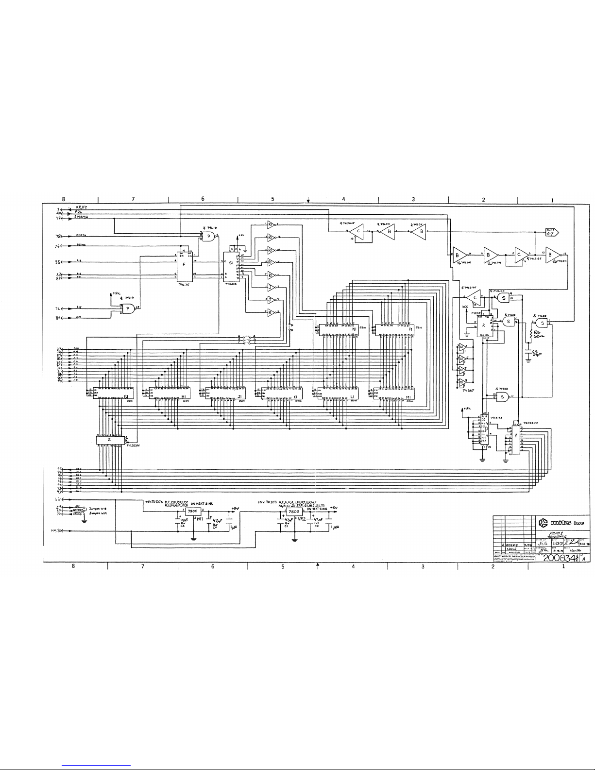
Auto-Start
IC R (74LS93) is a binary counter that serves as a sequencer for the
auto-start function. This counter is reset by power-on clear, and
counts through the four states of the auto-start sequence before
stopping.
State 1: Force “JMP” instruction (303 octal) onto the bus
State 2: Force low address (000 octal) onto the bus
State 3: Force high address (300 octal) onto the bus
State 4: Release the bus
IC D (74LS153) creates the three data patterns that are forced onto
the bus, based on the sequencer’s state. IC Y (74LS244) gates these
data patterns onto the bus during the first three states of the
sequencer.
Data is forced onto the bus by overdriving the SMEMR signal on the bus
with IC X1 (74LS367), using four drivers in parallel to overdrive the
SMEMR signal that is generated on the CPU board. By forcing SMEMR to a
false state, the memory board that is addressed at address 0 will not
respond, and the data patterns generated by the auto-start circuit
will be executed by the CPU.
Basic ROMs
MITS Extended Cassette Basic is permanently written into eight 8316
ROMs, in locations G1, H1, J1, K1, L1, M1, N1, and P1. Note that P1
Page 8

6
(on the right) is the lowest-address ROM socket, and G1 (on the right)
is the highest-address ROM socket.
IC S (74 LS138) decodes which individual ROM is addressed, based on
versions of address bits A11, A12 and A13 that are latched by IC F
(74L75). The ROMs are addressed when both A14 and A14 are high, as
determined by the NAND gate at IC P (74L10). ROM data is gated into
the bus by IC Z (74LS244) when any of the ROMs is addressed, and when
PDBIN and SMEMR are both active.
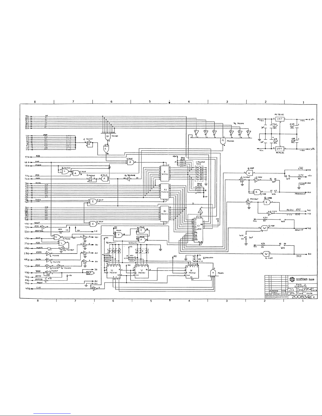
Sense Switches
SW-2 has a DIP switch for each of the 8 data bits. A data bit will be
low if the switch is closed (grounding that bit, and will be pulled to
a high state by resistor pack RP2 (4.7 K-ohms) if the switch is open.
IC X (74LS244) gates the sense switch data onto the bus when the CPU
inputs from I/O port 377 (octal). IC D1 (74LS30) recognizes 377
(octal) on the address bus, and IC A (74L10) recognize a port input
cycle.
Serial Port
The serial port is based on the 6850 ACIA at IC C1.
The ACIA drives its data pins when PDBIN is active and the ACIA is
addressed during an I/O input cycle. ICs E1 (74LS04) and F1 (74LS30)
recognize 20 and 21 (octal) on the address bus, and IC E (74L10)
recognize a port input cycle. Address signal A0 determines whether the
ACIA drives its data channel or its status channel onto its data pins.
IC A1 (74LS244) gates the ACIA data onto the bus when the CPU inputs
from I/O port 20 or 21 (octal).
IC B1 (74LS244) drives the bus data onto the ACIA data pins when the
CPU performs any output cycle. If the output is to ports 20 or 21
(octal) then the ACIA will latch the data on the trailing edge of the
–PWR bus signal. Address signal A0 determines whether the ACIA data
channel or control channel is written to.
IC K (1488) and IC W (1489) serve as RS-232 drivers and receivers when
RS-232 levels are used. IC J (7404) is used to drive TTL signals. The
1489 also serves as the TTL-level receiver.
Pullup resistors R3, R4, and R5 (4.7 K-ohms) are available for unused
signal inputs, and are put in circuit with jumpers W13, W14, and W15.
C5 (1 uF) is available for slew-rate control on the RxD signal. This
capacitor is put in circuit with jumper W12.
Baud Rate Generator
The baud rate generator uses the 2 MHz CLK signal from the bus for its
time base.
ICs U, V, and H (all 74LS161s) form a 12-bit synchronous counter that
is clocked by the CLK signal. This counter counts up, and is re-loaded
with the value set by DIP switch SW-1 when it overflows. Thus, the SW1 controls the frequency of it reload signal, as detected by IC T
(74LS13). Note that to minimize the number of DIP switches, several
counter-reload bits are tied together. This has the side effect of
Page 9

7
eliminating several common baud rates. Also note that the switches are
not in bit-order.
The counter-reload signal is too short to be used as the ACIA clocks,
so it is stretched by the flip-flop constructed with IC E and IC P
(both 74L10s) to produce the ACIA transmit and receive clocks.
Assembly
Errata
The following rework is required to correct a PCB layout mistake:
1. Cut the trace on the component side (near IC A) that goes from IC A
pin 9 to IC E pin 13.
2. Cut the trace on the solder side that goes from IC A pin 9 to IC A
pin 13
3. Install a jumper on the solder side from IC A pin 4 to IC A pin 9.
(Do this after sockets are installed for IC A.)
4. Install a jumper from IC S pin 1 to IC E pin 13. (Do this after
sockets are installed for ICs E and S.)
Install Axial Components
1. (1) 1K-ohm 1/4W resistor at R1
2. (3) 4.7K-ohm 1/4W resistors at R3, R4, and R5
3. (1) 68 ohm 1/4W resistor at R6
Install IC Sockets
1. (20) 14-pin DIP sockets at A,B,C,E,J,L,K,M,N,P,R,S,T,W,D1,E1,F1
P1,RP1,RP2
2. (9) 16-pin sockets at D,F,G,H,U,V,S1,T1,X1
3. (5) 20-pin sockets at X,Y,Z,A1,B1
4. (9) 24-pin sockets at C1,G1,H1,J1,K1,L1,M1,N1,P1
Install Switches
1. (2) 8-position DIP switches at SW-1 and SW-2. Orient them such that
“ON” is to the right.
Install Radial Components
1. (4) 47 uF 16V (or higher) electrolytic or tantalum capacitors at
C1,C2,C3,C4
2. (1) 1 uF 16V (or higher) tantalum capacitor at C5
3. (4) 22 uF 35V (or higher) electrolytic or tantalum capacitors at
C8,C9,C10,C11
4. (1) 27 pF ceramic capacitor at C12
5. (20) 0.1 uF capacitors at all 20 “SC” locations
Install TO-92 Components
1. (1) 79L12C at VR4
2. (1) 78L12C at VR5. NOTE: This component should be installed
backwards from the silkscreen indication, such that the flat side
of the 78L12C faces downward.
Page 10

8
Install TO-220 Components
1. (2) 7805, with heat sink grease, heat sink, 3-30 screws and nuts at
VR1,VR2
Install Jumpers
These may be installed on either side of the board, though the look
better when installed on the component side.
1. A-A
2. B-B
3. C-C
4. D-D
Install Standard DIP Components in Sockets
1. (1) 74L00 at S
2. (1) 74LS02 at L
3. (2) 7404 at J,R1
4. (1) 74L04 at B
5. (2) 74LS04 at M,E1
6. (3) 74L10 at A,E,P
7. (1) 74LS13 at T
8. (2) 74LS30 at D1,F1
9. (1) 74L75 at F
10. (1) 74LS93 at R
11. (2) 74LS125 at C,N
12. (1) 74LS138 at S1
13. (1) 74LS153 at D
14. (3) 74LS161 at H,U,V
15. (5) 74LS244 at X,Y,Z,A1,B1
16. (2) 74367 at X1,T1
17. (1) 74LS367 at G
18. (2) 4.7K-ohm, 13-resistor resistor packs at RP1,RP2
19. (1) 1488 at K
20. (1) 1489 at W
21. (1) 6850 at C1
Install ROMs
The eight 8316 ROMs are programmed with MITS Extended Cassette Basic,
and are each labeled with a unique part number. Install the ROMs in
sockets as follows:
Part Number Location
101481 or MP1481 P1
101482 or MP1482 N1
101483 or MP1483 M1
101484 or MP1484 L1
101485 or MP1485 K1
101486 or MP1486 J1
101487 or MP1487 H1
101488 or MP1488 G1
Page 11
Page 12
 Loading...