

Mitre-Mite VN 42 Instruction Manual
Mitre-Mite
VN 42
Instruction Manual
Version I
®
100 Fairway Drive Suite 114 Vernon Hills, IL 60061
Phone: 1-800-322-4204
Fax: 1-800-426-7019
1

Index
1. GENERAL INFORMATION 3
1.1 PRODUCER 3
1.2 ASSISTANCE CENTERS 3
1.3 CERTIFICATION 3
1.4 WARRANTY 3
1.5 PRE-ARRANGEMENTS CHARGED TO THE
CUSTOMER 3
1.6 HANDBOOK STRUCTURE 3
1.6.1 Object and contents 3
1.6.2 Users 3
1.6.3 Preservation 3
1.6.4 Symbols utilized 4
2. MACHINE DESCRIPTION 5
2.1 WORKING PRINCIPLE 5
2.2 MAIN COMPONENTS 5
2.3 MACHINE STRUCTURE 5
2.4 DIMENSIONS 5
2.5 SURROUNDING CONDITIONS 5
2.6 LIGHTING 5
2.7 VIBRATIONS 5
2.8 NOISE EMISSIONS 5
2.9 TECHNICAL DATA 6
2.10 STANDARD EQUIPMENT 6
2.10.1 Standard accessories 6
2.10.2 Upgrading and implementing of mechanical parts 6
2.10.3 Optional accessories 6
2.10.4 Customized optional accessories 6
2.11 ELECTROMAGNETIC AMBIENT 6
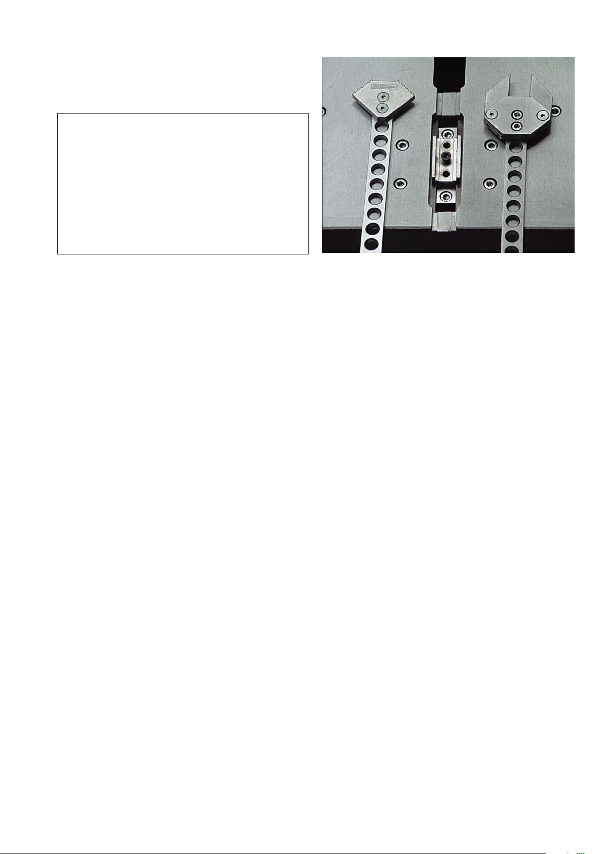
4.8.2 V-nail guide head replacement to change
V-nails size 11
4.9 ADJUSTMENTS 11
4.9.1 Setting stops for V-nails positioning 11
4.9.2 Vertical clamp adjustment 12
4.9.3 Horizontal clamp adjustment 12
4.9.4 Fences adjustment 12
4.9.5 Protective shield adjustment 13
4.9.6 Working pressure adjustment 13
4.10 CHECKING OPERATIONS TO BE EFFECTED
BEFORE WORKING START 14
5. FUNCTIONING 14
5.1 OPERATORS 14
5.2 FUNCTIONING DESCRIPTION 14
5.3 TIPS FOR PERFECT JUNCTIONS 14
5.4 MACHINE STOP 15
5.5 MACHINE REINSTATEMENT 15
5.6 PUTTING OUT OF SERVICE 15
6. MAINTENANCE 15
6.1 STATE OF MAINTENANCE 15
6.2 MACHINE ISOLATION 15
6.3 SPECIAL PRECAUTIONS 15
6.4 CLEANING 15
6.5 LUBRICATION 16
6.6 ORDINARY MAINTENANCE 16
6.7 EXTRAORDINARY MAINTENANCE 16
7. DIAGNOSTIC 17
7.1 SAFETY WARNINGS 17
7.2 TROUBLESHOOTING 17
7.3 REQUEST OF ASSISTANCE 18
8. SPARE PARTS 19
3. SAFETY 7
3.1 GENERAL WARNINGS 7
3.2 SCHEDULED USE 7
3.3 INADVISABLE USE 7
3.4 DANGEROUS AREAS 7
3.5 PROTECTION DEVICES 7
3.6 STOP FUNCTIONS 7
3.7 SAFE WORKING PROCEDURES 7
3.8 RESIDUAL RISKS 8
3.9 PLATES 8
4. INSTALLATION 8
4.1 SHIPPING AND HANDLING 8
4.2 STORAGE 9
4.3 PRELIMINARY ARRANGEMENTS 9
4.4 UNPACKING 9
4.5 MACHINE POSITIONING 9
4.6 CONNECTIONS 9
4.6.1 Pneumatic connection 9
4.7 PRELIMINARY CONTROLS 10
4.8 MACHINE ARRANGEMENT 10
4.8.1 V-nails magazine loading 10
8.1 SPARE PARTS LIST 19
8.2 SPARE PARTS ORDERING 19
9 DEMOLITION 19
9.1 DEMOLITION 19
10. ATTACHMENTS 19
10.1 DECLARATIONS 19
10.2 SCHEMES 19
2
1. GENERAL INFORMATION
1.1 PRODUCER
The firm Alfamacchine - ITW/AMP can boast more than 10
years of experience in the construction of Woodworking
Machines. It is the acquired technological know-how,
developed during years of researches in strict touch with
manufacturing department and international
commercialization the best warranty that Alfamacchine can
grant to its customers.
TEL 1-800-322-4204 FAX 1-800-426-7019
The warranty also decays in case you use V-nails different
from the original ITW/AMP ones.
To take advantage of warranty services, it is necessary at the
moment you receive your machine to completely fill out
the warranty card and send it back as soon as possible to
ITW/AMP.
The warranty will be valid after the ITW/AMP records it.
1.2 ASSISTANCE CENTERS
ITW/AMP is represented both in North and South America
by a numerous and prepared sales organization. Contact
our firm to get the number of your local distributor.
For every need regarding Use, Maintenance or Request of
Spare Parts, the Customer should call the authorized service
centers or directly to ITW/AMP, specifying the machine
identification data impressed on the plate.
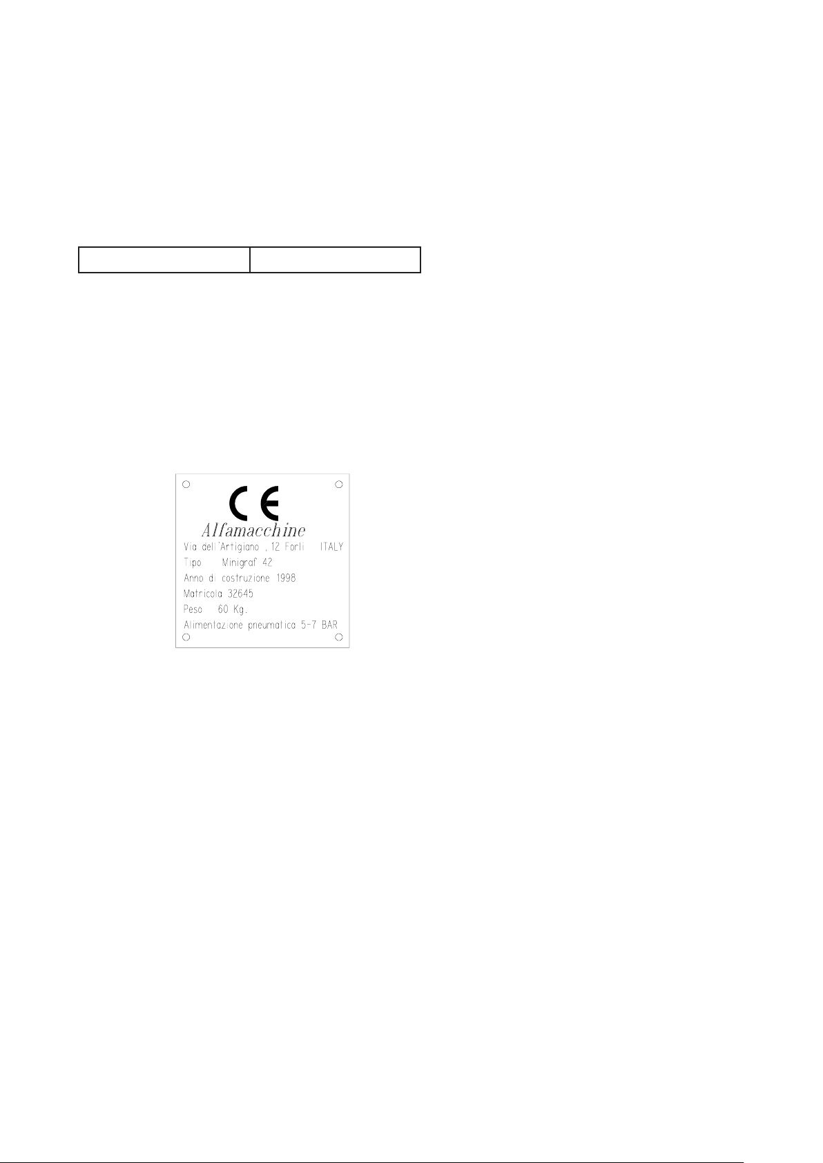
1.3 CERTIFICATION
The machine is produced in conformity to the pertinent
European Community Norms in force at the moment of its
introduction on the market.
1.4 WARRANTY
ITW/AMP’s products are constructed to have a long life and
are tested one by one.
If, in spite of this if any damages or malfunctioning would
occur, the replacement of defective parts is warranted
(counting from the date written on the delivery bill) for a
period of:
- 24 months for mechanical components
- 12 months for pneumatic part
The driver blade is tested for about 1.000.000 working
cycles.
The Warranty does not include the sending of technical staff.
The repair interventions will be performed at ITW/AMP and
the freight of shipment will be entirely charged to the
Customer.
The warranty does not cover the damages caused by an
inappropriate use of the machine or not corresponding to
the instructions described in this handbook.
The warranty decays in case of unauthorized modifications
or because of accidental damages or tampering performed
by unqualified personnel.
1.5 PRE-ARRANGEMENTS CHARGED TO THE CUSTOMER
It is the customer’s duty, on times agreed with the producer,
to execute what is indicated in our documentation.
Things normally charged to the customer:
• Premises predisposition, included building works and/
or canalization eventually requested
• Pneumatic supply of compressed air (see the paragraph
4.9.6)
1.6 HANDBOOK STRUCTURE
The customer must pay an extreme attention to the
indications reported in this handbook. The proper PreArrangement, Installation and Use of the Machine,
constitute the basis of a correct customer-distributor
relationship.
1.6.1 Object and contents
The goal of this handbook is to provide to the customer all
the necessary information so that, besides the proper use of
the machine, He would be able to run it in complete
autonomy and safety. The handbook contains information
concerning the technical aspects, machine working and
standstill, maintenance, spare parts and safety. Before making
any operation on the machine, the qualified technicians
and operators must carefully read these instructions. In case
you are in doubt about the correct interpretation of these
instructions, call your distributor & have them explanation
it to you.
1.6.2 Users
This handbook is made both for operators and technicians
authorized to the machine maintenance.
The operators can not execute operations reserved to the
maintainence staff or to the qualified technicians.
The producer does not answer to damages derived from notobserving this prohibition.
1.6.3 Preservation
The instruction handbook must be kept very closed to the
machine & in a special container protecting it from liquids
and whatever could compromise its legibility
3
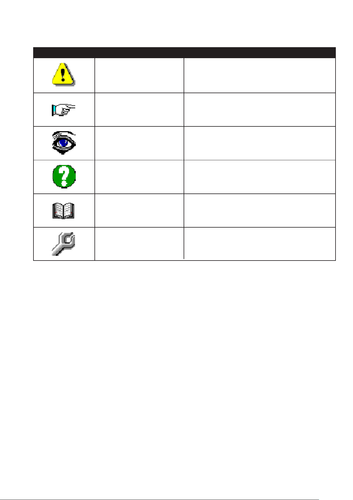
1.6.4 Symbols utilized
P...
A...
O...
I...
C...
DANGER
WARNING
OBSERVATION
INQUIRY
EXAMINATION
ADJUSTMENT
It indicates a danger with a mortal risk for the operator
It indicates a warning or a note about key functions or useful
information. Pay the maximum attention to the paragraph
marked with this symbol.
Requests you to take a measurement data, to check a
signal,....
The user is requested to check the proper positioning of any
element of the machine, before operating a certain command
It’s necessary to consult the handbook before performing a
certain operation
In case of strange working and/or anomalies, it can be
requested to make a certain mechanical adjustment
R...
4
2. MACHINE DESCRIPTION
2.1 WORKING PRINCIPLE
The Mitre-Mite VN 42 is a pneumatic frame assembling
machine particularly suitable with large sized frames.
The frame assembling machine Miter Mite VN 42 uses
V-nails with “pulling power” in different sizes.
2.2 MAIN COMPONENTS
The main components constituting the machine are:
• Frontal clamping device to have a perfect joint.
• Position brake to easily insert intermediate V-nails in
any profile
• Adjustable tilting fences.
• Floor stand
• Dual function foot pedal for separate control of clamping
and nail insertion
• Nail heads sizes 7, 10 and 15 mm.
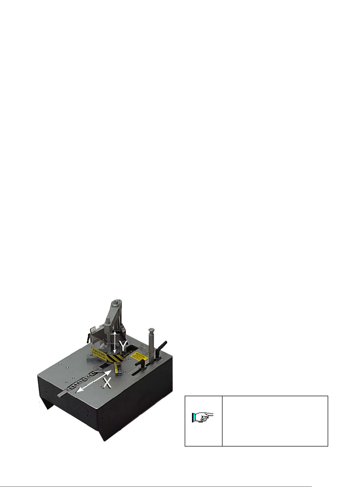
2.3 MACHINE STRUCTURE
The movement directions during the machine working are
the followings:
- X AXIS
Movement of the horizontal clamp
- Y AXIS
Movement of vertical clamp
2.4 DIMENSIONS
The overall dimensions are reported on table 2.9-A
2.5 SURROUNDING CONDITIONS
The machine does not need special surrounding conditions.
It has to be installed inside an industrial building, lit, aired
and with a compact and flat floor. The admitted temperatures
go from 41°F to 104°F (, with an humidity not higher than
50% at 104° F or 90% at 68° F.
2.6 LIGHTING
Premises lighting must be conformed to the norms in force
in that Country where the machine is installed and has to
guarantee a clear visibility and can not create dangerous
situations.
The average quadratic weighed level, according to the
acceleration frequency to which arms are exposed does not
exceed 2,5 m/s2.
2.7 VIBRATIONS
In standard conditions conformed to the indication of
machine proper utilization, the vibrations do not create
dangerous conditions. The average quadratic weighed level,
according to the acceleration frequency to which arms are
exposed does not exceed 2,5 m/s2.
2.8 NOISE EMISSIONS
The machine is designed and projected for reducing the
noise emission level to its source. In standard working
conditions the Machine noise power level is:
Acoustic Continuous Equivalent weighed
pression A <70dB
Acoustic Istantaneous weighed
pression <130dB
The noise levels indicated are emission levels and are not
representative of operating levels. In spite of an existing
relationship between emission levels and exposure ones,
this can not be used in a reliable way to define if further
precautions are necessary. The factors determining the
exposure level to which the working force is subjected,
include exposure length, working premises characteristics
and other noise sources (number of machines, closed bldg,
etc…). Furthermore, the allowed exposure levels could
change according to several different Countries. At any rate,
the information provided, will allow the Machine Operator
to achieve a better evaluation of the danger and risks he is
submitted to.
The indicated noise levels are emission
ones measured in standard conditions of
use. In case of any machine modification,
the above mentioned levels could be
changed and should be checked on the
same machine.
5
2.9 TECHNICAL DATA
We have listed below the Machine data and technical
characteristics. You can use it for reference for any eventual
contact with the Producer for Technical Assistance.
-Frames thickness min-max 1/4”- 2.75”
-Frames widthmin-max 3/8”- 4.75”
-Max distance among V-nails 4.75”
-V-nail magazine capacity n. 230
-V-nails size 7, 10, 15 mm.
-V-nails size on request 3, 5, 12 mm.
-Pneumatic supplying 50-100 PSI
-Weight about 132lb
-Height of working bench adjustable
-Overall dimensions 20”x17”x49”
2.10 STANDARD EQUIPMENT
The equipment listed below are the standard ones.
2.10.1 Standard accessories
Once you have removed the packaging, please check the
presence of the following accessories.
-N.1 nail head mm. 7
-N.1 nail head mm.10
-N.1 nail head mm.15
-N.1 L shaped pressure pad in rubber
-N.1 Allen Wrench 5 mm. for V-nails head replacement
-N.1 Brass rod magnet to remove V-nails
Picture 1
2.10.4 Customized optional accessories
Thanks to its versatility this machine can be ‘custom-made’
to meet our users’ requirements. You can have your local
machine shop make accessories that can make frame
assembling easier: e.x. special fences for peculiar shaped
moulding shapes, special clamps to ensure the mouldings
are locked properly during V-nail f iring, and so on.
2.11 ELECTROMAGNETIC AMBIENT
The Machine is designed to operate properly in an industrial
electromagnetic ambient without altering it being an
exclusively pneumatic machine.
2.10.2 Upgrading and implementing of mechanical
parts
The machine has been manufactured following a modular
criterion, therefore the existing equipment can be further
upgraded with additional accessories that will not alter its
basic structure.
Technical upgrades on the machine model, if any, will be
such that they can be installed at any time without requiring
any substantial modifications to the machine’s structure.
2.10.3 Optional accessories
• Wooden working bench extension
• Metallic working bench extension
• V-nails claw heads size 3-5-12 mm.
• Spring loaded front clamp (see fig.1)
6
3. SAFETY
3.1 GENERAL WARNINGS
The operator pay the maximum attention to the information
written in this Handbook. It is very important you read about
the proper precautions for Safety listed in this chapter.
It is indispensable for the operator to follow the warnings
listed below:
• Keep the machine and the working premises clean &
ordered
• Provide appropriate containers to stock the moulding
you will be working with.
• Use the Machine only in normal psycho physical
condition
• Wear adequate clothing to avoid obstacles and/or
dangerous entanglements to/from the machine
• Wear the individual protection equiptment described
by the instructions handbook.
• Do not remove or alter the warning plates and adhesive
signs
• Do not remove or elude the Machine Safety Systems
• Keep the fingers away from the working area
• Disconnect the air pressure supply during any
maintenance intervention
• Keep your foot separeted from the pedal during Machine
maintenance
3.2 SCHEDULED USE
The Machine is designed and built to assemble frames.
The machine is projected for manual use only (under operator
control).
3.3 INADVISABLE USE
The machine can not be used for:
• For uses different from those listed in paragraph 3.2
• In an explosive or aggressive atmosphere, where there
is a high density of dust or oily substances suspended
in the air
• In a flammable atmosphere
• Outside in all weather severity
• For working with materials not suitable with the
machine’s characteristics
3.4 DANGEROUS AREAS
The area where the frames are assembled is defined as the
“working area”.
The dangerous areas of machine, include the movable parts
and the surrounding zones.
Picture 3.4.A- Working area and dangerous zones
DANGEROUS ZONE
3.5 PROTECTION DEVICES
The machine is equipped with adequate protections for
persons exposed to the risks of using this machine, taking
into consideration the working parts. (driver blade, horizontal
clamp, vertical clamp).
3.6 STOP FUNCTIONS
The machine stop functions are the following:
• Fast clutch fitting stop (Category 0).
• Foot pedal Stop (Category 1).
STOP CATEGORY 0
It is obtained by disconnecting the fast clutch fitting from
the feeding system (uncontrolled stop).
STOP CATEGORY 1
Controlled stop obtained by lifting the foot from the
pneumatic pedal, which will not allow the v-nails to fire.
3.7 SAFE WORKING PROCEDURES
The machine is projected and realized to
eliminate any risk connected with its use.
The user is requested to achieve an adequate
training to be instructed by your local
distributor or ITW/AMP’s technicians.
The other risks related with using this machine are:
- Finger crushing in the vertical clamp working area
- Finger crushing in the frontal clamp working area
It is necessary to carefully follow the instructions listed
below:
1 Keep the fingers away from frontal and vertical clamp
working areas
2 Disconnect the air pressure and during any maintenance
interventions
3 Keep the foot away from the pedal while peforming
machine maintenance.
7
3.8 RESIDUAL RISKS
During the normal working cycle and while maintaining the
machine, the operators are exposed to several residual risks
that, because of the operations own nature can not be totally
eliminated.
• Risk of f inger crushing in the working areas of vertical
and frontal clamps
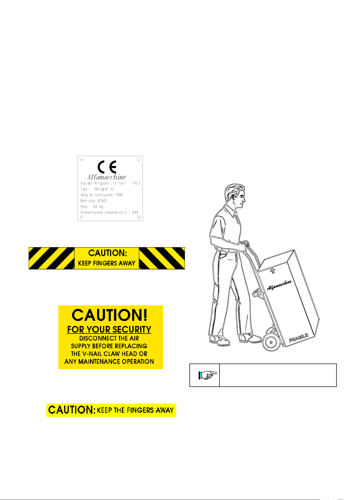
3.9 PLATES
The warning plates carry out safety functions can not be
removed, covered or damaged.
To see the plates or adhesive signs location, consult the
Fig.10.2-D
Table 3.8 A- Types of plates
4. INSTALLATION
4.1 SHIPPING AND HANDLING
The shipment must be performed by professionally qualified
staff. The machine has to be shipped in a safe way to avoid
any damage to its parts.
• All the protections and guard devices must be properly
closed and clamped.
• The machine has to be shipped like it is positioned for
installation.
• Before shipment it is necessary to lubricate the parts
which are not painted.
• According to the type of shipment, it is necessary to
protect the machine from any jarring impact or stress
Picture 4.1A – machine handling indications
Machine total weight: about 70 Kilos
Plate concerning the machine’s characteristics
Adhesive sign concerning the finger danger zone
Adhesive sign concerning the behaviour to be kept during
the working cycle
Adhesive sign concerning the behaviour to be kept during
the working cycle
Lifting the machine must be performed
by 2 operators.
Any damage of the machine caused during its shipment or
handling is not covered under warranty.
Repairs or replacement of damaged parts are charged to the
customer.
8
4.2 STORAGE
In case of long inactivity, the machine must be stored with
cautions concerning storage place and times.
• Store the machine indoors
• Protect the machine from jarring impacts and stresses
• Protect the machine from humidity and high
temperatures
• Avoid storing the machine near corrosive materials
• Lubricate the parts which are not painted
4.6 CONNECTIONS
To avoid any problems while setting up the machine, we
suggest you follow the instructions listed below.
4.6.1 Pneumatic connection
The Mitre-Mite VN 42 works by compressed air and is
controlled by a foot pedal & a thumb-button that allows the
activation of the frontal clamp,vertical clamp and V-nail
firing.
4.3 PRELIMINARY ARRANGEMENTS
To install the machine it is necessary to prepare a working
area adequate to the machine’s dimensions and the length of
moulding you will be using.
4.4 UNPACKING
The machin is shipped packed into an appropriate carton
and protected with polystyrene parts.
Remove the external packing and save it for future uses.
Check for any casual shipping damage and report them
immediately. Shipping damages or any other defects must
be reported to ITW/AMP within 3 days from the time
you receive the machine.
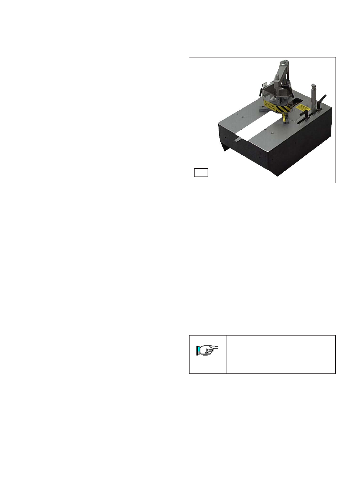
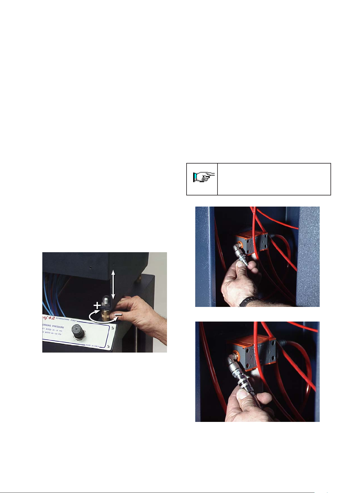
4.5 MACHINE POSITIONING
Position the machine in its working area. Adjust the height
of the machine by using the 4 screws. raise it up until you
reach the desired height (see fig. 2).
Attach your airline to the machine by using the provided
fast clutch fitting or a different fast clutch fitting suitable
with your pneumatic system.
Screw the fitting (see fig. 3-4) into the air filter located on
the right side of the floor stand.
Take the pressure gauge out from the floorstand and screw it
onto the air filter. Then connect your air supply line to the
machine.
It is advisable that you use silicone oil for
pneumatic systems. Avoid generic lubricating
oil. The use of inappropriate oil could damage
the valves.
Picture 2
Picture 3
Picture 4
9
 Loading...