

Page 1
Operator’s Manual
user manual, maintenance instructions and spare parts
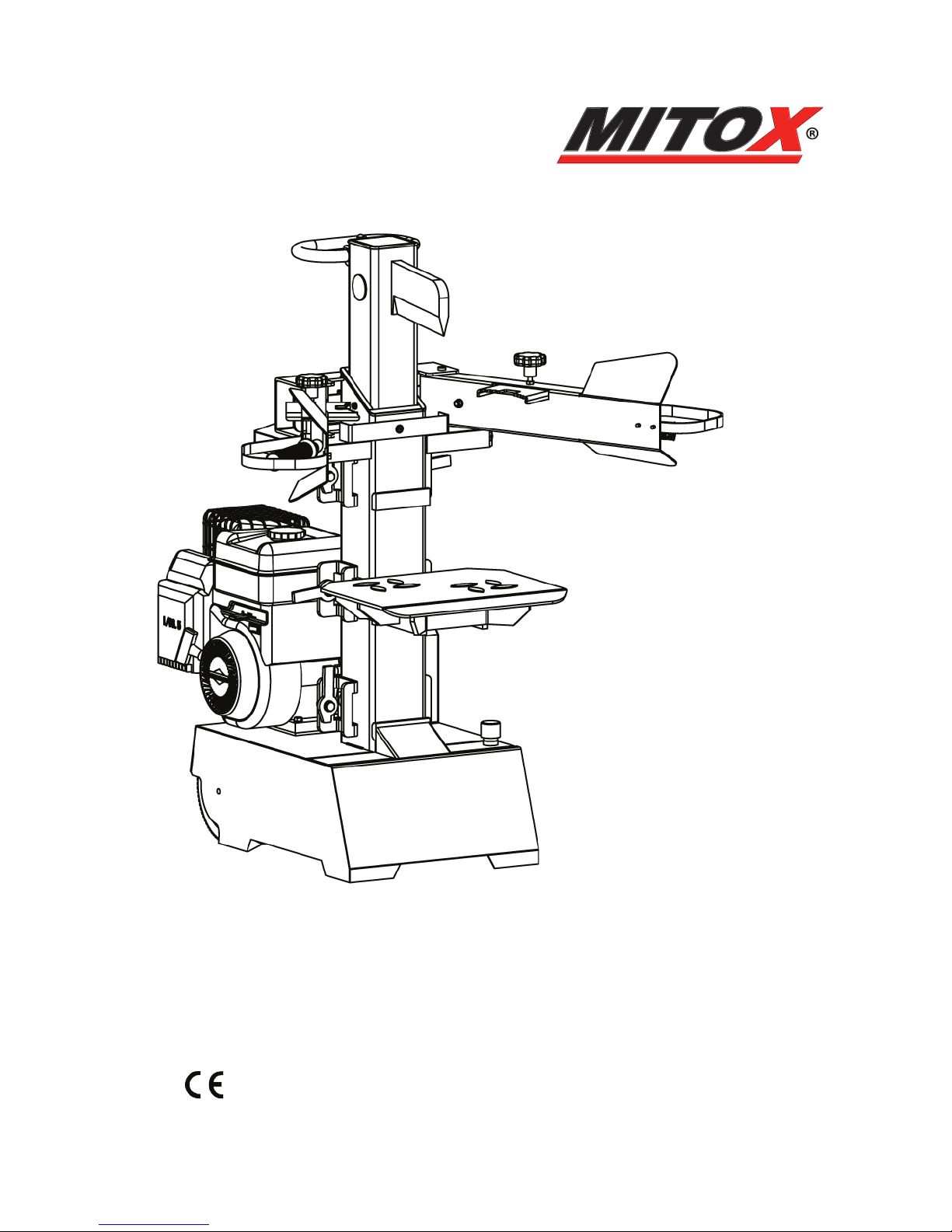
LS700BS 7 Ton Petrol Logsplitter
www.mitoxgm.co.uk
Read this manual carefully before operating the machine
Original Instructions Version April 13
Page 2

LS700BS 7 Ton Petrol Logsplitter
2
Original Instructions Version April 13
SAFETY WARNINGS & EXPLANATION OF SYMBOLS ON THE MACHINE
UNDERSTAND YOUR LOG SPLITTER
Read and understand the owner’s manual and labels axed to the log splitter. Learn its
application and limitations as well as the specic potential hazards peculiar to it.
DRUGS, ALCOHOL AND MEDICATION
Do not operate the log splitter while under the inuence of drugs, alcohol, or any medication
that could aect your ability to use it properly.
AVOID DANGEROUS CONDITIONS
Always operate your log splitter on dry, solid, level ground. Never operate your log splitter on
slippery, wet, muddy, or icy surfaces. Keep your work area clean and well lit. Cluttered areas
invite injuries. Do not use the log splitter in wet or damp areas or expose it to rain. Do not
use it in areas where fumes from paint, solvents or ammable liquids pose a potential hazard.
INSPECT YOUR LOG SPLITTER
Check your log splitter before turning it on. Keep guards in place and in working order.
Replace damaged, missing or failed parts before using it. Make sure all nuts, bolts, screws,
hydraulic ttings, hose clamps, etc. are securely tightened. Always check the oil level in the
hydraulic oil tank. Never operate your log splitter when it is in need of repair or is in poor
mechanical condition.
WORK WEAR
Do not wear loose clothing, neckties or jewellery (rings, wrist watches). They can be caught in
moving parts. Protective gloves and safety footwear are recommended when working. Wear
protective hair covering to contain long hair, preventing it from getting caught in machinery.
PROTECT YOUR EYES AND FACE
Any log splitter may throw foreign objects into the eyes. This can cause permanent eye
damage. Always wear safety goggles. Everyday eyeglasses have only impact resistant lenses.
They are not safety glasses.
PREVENT FIRES
Do not smoke or have open ames when operating or refuelling the log splitter. Never
operate the log splitter near a ame or spark. Oil is ammable and can be ignited.
KEEP BYSTANDERS AWAY
Allow only one person to load and operate the log splitter. Always keep bystanders, including
visitors, children and pets away from the work area, especially when the log splitter is under
operation. Only the operator should stand near the machine and only within the safe
operating area of 5 metres. Never use another person to help you with freeing a jammed
log. No one under the age of 16 should be allowed to operate the log splitter. Any individual
under the age of 18 should always be under the supervision of an an adult.
INSPECT YOUR LOG
Never attempt to split logs containing nails, wire or debris. Always make sure that both ends
of the log you are splitting are cut as square as possible. This will prevent the log from sliding
out of position while under pressure. Branches must be cut o ush with the trunk.
Page 3

LS700BS 7 Ton Petrol Logsplitter
3
Original Instructions Version April 13
DON’T OVERREACH
Keep a proper footing and balance at all times. Never stand on the log splitter. Serious injury
could occur if the tool is tipped or if the cutting tool is unintentionally contacted. Do not store
anything above or near the log splitter where anyone might stand on the tool to reach it.
AVOID INJURY FROM UNEXPECTED ACCIDENT
Do not straddle or reach across the splitting area when operating the log splitter. Never pile
logs to be split in a manner that will cause you to reach across the log splitter. Only use your
hands to operate the control levers. Never use your foot, knee, a rope, or any other extension
device. Always pay full attention to the movement of the wedge ram. Never attempt to load
your log splitter while the ram is in motion. Keep hands out of the way of all moving parts.
Never try to split two logs. One of them may y up and hit you.
PROTECT YOUR HANDS
When the ram of the log splitter is in the return mode, keep your hands o the machine – the
log splitter is designed to automatically stop when the cylinder is fully retracted. Keep your
hands away from splits and cracks which open in the log. They may close suddenly and crush
or injure your hands. Do not remove jammed logs with your hands.
INCORRECT USE
The log splitter will do a better and safer job working at its designed rate. Don’t use the log
splitter for a purpose for which it was not intended. Do not, under any circumstances, alter
your log splitter. This equipment was designed and engineered to be used in accordance with
the operating instructions. Altering the equipment, or using the equipment in such a way as
to circumvent its design capabilities and capacities, could result in serious or fatal injury and
will void the warranty. Never try to split logs larger than those indicated in the specications
table. This could be dangerous and may damage the machine.
NEVER LEAVE THE LOG SPLITTER RUNNING UNATTENDED
Don’t leave the tool until it has come to a complete stop.
FOR YOUR SAFETY
Do not remove or tamper with any of the machines protection or safety devices or modify
the log splitter in any way.
PROTECT THE ENVIRONMENT
Take used oil to an authorized collection point or follow the stipulations in the country where
the log splitter is used. Do not discharge into drains, soil or water.
MAINTAIN YOUR LOG SPLITTER WITH CARE
Always clean the unit after each use. Keep the log splitter clean for best and safest performance.
Follow the instructions for lubricating. Inspect all hydraulic seals, hoses and couplers for leaks
prior to use. Control levers and power switch must be kept clean, dry and free from oil and
grease at all times.
MAKE THE WORKSHOP CHILDPROOF
Lock the shop. Store the log splitter away from children and others not qualied to use it.
Page 4

LS700BS 7 Ton Petrol Logsplitter
4
Original Instructions Version April 13
UNDERSTAND YOUR MACHINE
Read and understand the operator’s manual and labels axed to the machine. Learn its
application and limitations as well as the specic potential hazards peculiar to it.
Be thoroughly familiar with the controls and their proper operation. Know how to stop the
machine and disengage the controls quickly.
Make sure to read and understand all of the instructions and safety precautions as outlined
in the Engine Manual, packed separately with your unit. Do not attempt to operate the
machine until you fully understand how to properly operate and maintain the Engine and
how to avoid accidental injuries and/or property damage.
WORK AREA
Never start or run the engine inside a closed area. The exhaust fumes are dangerous,
containing carbon monoxide, an odorless and deadly gas. Operate this unit only in a well
ventilated outdoor area.
BURN RISK
Take care not to touch the hot muer/exhaust, gear housing and cylinder.
TABLE OF CONTENTS
Safety Warnings & Cautions .….….….….….….….….….….….…………………………………………………………………..........2
Application Conditions ....….….….….…………….….….….….……………………………………………………………….…….....5
Specifications….….….……………………………….….….….….….………………………………………………..........5
Contents of Container …..….….….….….….….….….….….….….…………………………………………………………………. .....6
Set up and Preparation for Operation…….……….….….….….….….….….….…………………………………………………….......6
Delivering Log Splitter to Work Site ..….….….….….….….….….….….….….….….…………………………………......................................7
Log Splitter Operation ...........…….….….….….….….….….….….….….………………………………………………………. ...................8
Replacing Hydraulic Oil ……….….….….….….….….….….….………………......…………………………………………………....9
Sharpening Wedge ............…….….….….….….….….….….….….….………………….............……………………………………….....10
Trouble Shooting ………………….….….….….….….….….….….….……………………………………………….............………....10
Wiring Diagram ………………….….….….….….….….….….….………………………………….……………………………..........10
Hydraulic Plumbing Diagram ………………….….….….….….….….….….….……………………………………………......…….10
Parts Schematic .....…………….….….….….….….….….….….….….….….….……………………………...........................................................11
Declaration of Conformity….….….….….….….….….….….….….….….….……………………………...........................................................14
Page 5

LS700BS 7 Ton Petrol Logsplitter
5
Original Instructions Version April 13
DESCRIPTION OF MACHINE
The log splitter is designed to be used in a domestic application.
The log splitter is designed exclusively for the following applications:
-Splitting freshly cut timber that does not exceed the dimensions specied in the technical data.
The 4-way splitting cross is only to be used on freshly cut wood and not seasoned wood as this type of wood
can splinter and put undue strain on the log splitter.
ENGINE INFORMATION
The Engine Manufacturer is responsible for all engine-related issues with regards to performance, power rating, specications,
warranty and service. Please refer to the Engine Manual, packed separately with your unit, for more information.
APPLICATION CONDITIONS
This log splitter is designed for operating under ambient temperatures between +5ºC and 40ºC. It can be stored or transported under
ambient temperatures between -25ºC and 55ºC.
SPECIFICATIONS
Model Number LS700
Motor 196cc, 6.5 HP
Max rpm 3600
Log Capacity Diameter 12cm - 32cm
Length 104cm / 78cm / 52cm
Maximum Force 7 Ton
Hydraulic Pressure 2581 PSI
Hydraulic Oil Capacity 6 L
Ram Travel 475mm
Forward Speed 4.9cm / sec.
Retract Speed 22.3cm / sec
Noise Level 88.1dbA under no load ;
93.0dbA under full load
Overall Sizes Length 107cm
Width 46 cm
Height 103 cm
Weight 125kg
ENVIRONMENTAL INFORMATION
Recycle unwanted materials instead of disposing of them as waste. All tools, hoses and packaging should be
sorted, taken to the local recycling center and disposed of in an environmentally safe way.
Page 6

LS700BS 7 Ton Petrol Logsplitter
6
Original Instructions Version April 13
FUEL SAFETY
Fuel is highly ammable, and its vapours can explode if ignited. Take precautions when using the log splitter to reduce the chance of
serious personal injury.
When relling or draining the fuel tank, use an approved fuel storage container while in a clean, well-ventilated outdoor area. Do not
smoke, or allow sparks, open ames or other sources of ignition near the area while adding fuel or operating the unit. Never ll the
fuel tank indoors.
Keep grounded conductive objects, such as tools, away from exposed, live electrical parts and connections to avoid sparking or
arcing. These events could ignite fumes or vapours.
Always stop the engine and allow it to cool before lling the fuel tank. Never remove the cap of the fuel tank or add fuel while the
engine is running or when the engine is hot. Do not operate a machine with known leaks in the fuel system.
Loosen the fuel tank cap slowly to relieve any pressure in the tank.
Never overll the fuel tank. Fill the tank to no more than 12.5mm (1/2”) below the bottom of the ller neck to provide space for
expansion as the heat of the engine and/or sun causes fuel to expand.
Replace all fuel tank and container caps securely and wipe up spilled fuel. Never operate the unit without the fuel cap securely in
place.
Avoid creating a source of ignition for spilled fuel. If fuel is spilled, do not attempt to start the engine but move the machine away
from the area of spillage and avoid creating any source of ignition until fuel vapours have dissipated.
Store fuel in containers specically designed and approved for this purpose.
Never store fuel or a machine with fuel in the tank inside a building where fumes may reach a spark, open ame, or any other sources
of ignition. Allow the engine to cool before storing in any enclosure. Drain fuel before transport.
Machines stored and not used for over 30 days need the fuel to be stabilised, or drained of fuel to prevent gum forming in the fuel
system, carburettor, petrol pump etc. We recommend the use of Briggs & Stratton fuel stabiliser (992381). Mix fuel stabiliser with fuel
in the fuel tank, or storage containers, and run the engine for a short time to circulate the stabiliser through the carburettor. Engine
and fuel can then be stored for up to 12 months.
SERVICE
Before cleaning, repair, inspecting, or adjusting, shut o the engine and make certain all moving parts have stopped. Always make
sure the engine’s throttle control is in its “STOP” position.
Disconnect the spark plug wire, and keep the wire away from the plug to prevent accidental starting.
Have your machine serviced by qualied repair personnel using only genuine replacement parts. This will ensure the safety of the
machine is maintained.
Page 7

LS700BS 7 Ton Petrol Logsplitter
7
Original Instructions Version April 13
CONTENTS OF THE CONTAINER
A. Log Splitter Frame …………................................1 set
B. Control Lever and Guard Assy................................2sets
C. Removable Support Table....…...............................1 pc
D. Owner’s Manual ……….....…….….....................1 pc
E. Cross Splitter ……….....…….….............................1 pc
SET UP AND PREPARATION FOR OPERATION
1. Pull Spring Pin (A) to remove the Lock Pin (B). Apply a thin coat of grease to both surfaces of the Control Lever Guard as illustrated.
Insert the Control Lever and Guard Assy and make sure the Control Lever End goes into the slot of Connection Bracket (C). Lock
the Control Lever and Guard Assy down with the Lock Pin (B) and Spring Pin (A). Follow the same steps to install the other Control
Lever and Guard Assy on the other side.
2. 3 installation positions are available for the Support Table for dierent splitting lengths. At every installation position, Lock Down
Hooks (D) are available. Insert the Support Table in the selected Brackets (E). Turn the Lock Down Hooks (D) on both sides by 90
degrees to lock the Support Table down.
A
E
Page 8

LS700BS 7 Ton Petrol Logsplitter
8
Original Instructions Version April 13
3. Familiarize yourself with the controls and features of
this log splitter as shown in the illustrations.
1. Transport Handle
2. Ram Travel Adjusting Rod
3. Split Wedge
4. Ram
5. Control Levers Connection Bracket
6. Top Motor Shield
7. Fuel Tank
8. Wheels
9. Base
10. Oil Tank Cover / Air Bleeder
11. Table Lock Down Hook
12. Support Table
13. Side Bracket for Support Table
14. Front Bracket for Support Table
15. Control Lever
16. Control Lever Guard
17. Adjustable Log Holder
18. Log Holder Adjusting Knob
Bleed the air out of the hydraulic system before starting the log splitter.
The bleed screw should be loosened by two rotations until air can go
in and out of the oil tank smoothly. Air ow through the oil tank ller
should be detectable during the operations. Before moving the log
splitter, make sure the bleed screw is tightened to avoid
oil leaking from this point.
THE FAILURE TO LOOSEN THE BLEED SCREW WILL
RESULT IN DAMAGE TO THE SEALS OF THE
HYDRAULIC SYSTEM AND CAUSE PERMANT
DAMAGE TO THE LOG SPLITTER.
DELIVERING THE LOG SPLITTER TO THE WORK SITE
The log splitter is equipped with 2 wheels for minor moving. To
move the log splitter to the work site. Grip the handle (A) to tilt
the log splitter slightly after making sure the bleed screw is
tightened.
If using a crane, lay hoist sling around the housing. Never try to
lift the log splitter at the Handle (A).
Page 9

LS700BS 7 Ton Petrol Logsplitter
9
Original Instructions Version April 13
LOG SPLITTER OPERATION
1. Plan your work site. Work safely and save eort by planning your work before
hand. Have your logs positioned where they can be easily reached. Have a site
located to stack the split wood or load it onto a nearby truck or other carrier.
2. Prepare the logs for splitting. This splitter accommodates logs up to 104cm
in length. When cutting up limbs and large sections, do not cut sections any
longer than 100cm. The 3 support table positions are for splitting logs up to
52cm, 78cm 104cm in length. Insert the support table in the position nearest to
the log length, and secure the support table with the locking hook.
Do not attempt to split seasoned logs. Green logs split much
more easily, and will not put undue pressure on the splitter.
Seasoned logs can also split violently, which can be dangerous
to the operator.
3. Applying a thin coat of grease to the surfaces of the ram before operation will
lengthen the durability of the ram.
4. Start the engine, following the procedure listed in the Briggs & Stratton engine
manual. The splitting wedge should rise to its highest position automatically.
5. Open the Air Bleed. Loosen the oil tank cover two turns whenever the splitter
is being used. Retighten this cover when you nish.
6. While operating under extremely low temperature, keep the log splitter
running under no load for 15 minutes to preheat the hydraulic oil.
7. Before initial operation, check to be sure the two-handed operation is properly
functioning by following these steps:
(1) Lower both control levers, splitting wedge lowers to approx 5cm
above the highest table position.
(2) Release either of the levers, splitting wedge should remain in the
original position.
(3) Release both levers, the ram should rise to the highest position
automatically.
8. To set the wedge ram stroke, take the following steps:
(1) Move the splitting wedge to desired position. The upper position of
the ram wedge travel should be about 3~5cm over the logs to be split.
(2) Release one control lever and switch o the engine
(3) Release the Setscrew (A) and Raise Adjusting Rod (B) until
Adjusting Rod (B) begins to be stopped by the spring inside. Tighten
the Setscrew (A).
(4) Release both control levers and start the engine
(5) Check upper position of splitting wedge.
Page 10

LS700BS 7 Ton Petrol Logsplitter
10
Original Instructions Version April 13
9. Place log onto splitter. Place the log onto the support table vertically and
sitting at on the support table. Be sure the wedge and support table will
contact the log squarely on the ends. Never attempt to split a log at an angle.
Split log in the direction of its growing grain. Do not
place logs across the log splitter for splitting. It may
be dangerous and may seriously damage the machine.
10. Adjust the Log Holders (A) according to the diameter of the log to obtain
most comfortable Control Levers angle.
11. Hold the log with the clamping brackets. Lower levers to start the
splitting. Releasing either lever stops the motion of the splitting wedge.
Releasing both handles returns the splitting wedge to the upper position.
12. Stack as you work. This will provide a safer work area, by keeping it
uncluttered, and avoid the danger of tripping.
4 WAY SPLITTING CROSS
Mount the 4 way splitting cross over the splitting wedge and secure in
place using the xing screw, ensuring that it is rmly secured.
The 4-way splitting cross is only to be used on freshly
cut wood and not seasoned wood as this type of wood
can splinter and put undue strain on the log splitter.
Accumulated split wood and wood chips can create a
hazardous work environment. Never continue to work in a
cluttered work area which may cause you to slip, trip or fall.
REPLACING HYDRAULIC OIL
The hydraulic system is a closed system with oil tank, oil pump and control
valve. Check oil level regularly with dipstick. Low oil level can damage the
oil pump. Oil Level should measure approx. 1 ~ 2 cm lower than the upper
surface of the oil tank. The oil should be completely changed once a year.
-Make sure moving parts stop and the log splitter is unplugged.
-Make sure that no dirt or debris nds its way into the oil tank
-Collect used oil and responsibly recycle.
-Following an oil change, activate the log splitter a few times without splitting
Hydraulic oil recommended for the log splitter’s hydraulic system:
HLP 22
Use a drain pan to aid in the removal of all used oil and particles.
Remove oil drain plug to drain oil from the hydraulic transmission
system. Examine oil for metal chips as a precaution to future problems.
After oil has been completely drained from the Oil ller, reinstall drain plug.
Fill the hydraulic transmission system with recommended oil through
the ller plug opening, to the correct level.
Page 11

LS700BS 7 Ton Petrol Logsplitter
11
Original Instructions Version April 13
Read dipstick to determine the maximum and minimum oil level.
To check the hydraulic oil, unscrew the oil ller plug and wipe the dip
stick rod with a clean cloth. Next insert the dip stick into oil tank without
screwing it into the tank. The oil should be between the markings Min
and Max. Top up the oil if necessary.
Low oil can damage the oil pump. Overlling can result in
excessive temperature in the hydraulic transmission system.
SHARPENING WEDGE
This log splitter is equipped with a reinforced splitting wedge with a specially treated blade. After long periods of operation, and
when required; sharpen the wedge using a ne-toothed le removing any burrs or at spots on the edge.
TROUBLESHOOTING
PROBLEM PROBABLE CAUSE REMEDY SUGGESTED
Engine does not start Engine oil level is low Fill engine with oil to correct level
Ignition switch is OFF Set ignition to ON
Log Splitter does not work while motor
running
Bleed valve is not opened Open bleed valve
Control Levers or Connection parts bent Replace the damaged parts
Low hydraulic oil level Check and rell hydraulic oil
Log Splitter works with
abnormal vibration and noise
Low hydraulic oil level Check and rell hydraulic oil
If the solutions above fail to resolve the problem or the machine is not safe to use then contact the suppying dealer.
HYDRAULIC
PLUMBING DIAGRAM
Page 12

LS700BS 7 Ton Petrol Logsplitter
12
Original Instructions Version April 13
Page 13

LS700BS 7 Ton Petrol Logsplitter
13
Original Instructions Version April 13
ID PART No DESCRIPTION QTY
1 MICCQ01 UPRIGHT TUBE WELDMENT - B&S 1
2 MICCQ62 PUMP GUARD 1
3 MIGG/T93-1987 SPRING WASHER M6 1
4 MIGB/T822-2000 SCREW M6X12 1
5 MIGB3452.1-92 O-RING 23.6X3.55G 1
6 MICCA.00.101 CAP 1
7 MIGB/T95-1985 WASHER M10 26
8 MICCA.00.109 LOCK-OUT LEVER 6
9 MIGB/T5781-2000 BOLT M10X35 8
10 MICCA.00.107 R/H CLAMPING FORK 1
11 MICCQ03.1.1 R/H GUARD ASSY 1
12 MICCA.00.125 KNOB M8X20 2
13 MICBC.40.113 FORK 2
14 MICCA.00.105 CONTROL LEVER SHAFT 2
15 MICCB.05.002 WORK TABLE 2 1
16 MICCA.00.122 PLASTIC INSERT (4) 1
17 MICCA.00.120 PLASTIC INSERT (2) 1
18 MICCA.00.119 PLASTIC INSERT (1) 1
19 MICCA.00.121 PLASTIC INSERT (3) 1
20 MICCA.00.106 L/H CLAMPING FORK 1
21 MICCQ04.1.1 L/H GUARD ASSY 1
22 MIGB/T822-2000 SCREW M6X10 6
23 MIGB/T95-1985 WASHER M6 6
24 MIGB/T802 LOCKNUT M10 6
25 MICFA.00.018 WHEEL A 2
26 MIGB/T894.1-1986 CIRCLIP 16 2
27 MIGB/T5786-2000 BOLT M16X15 1
28 MIJB982-77 WASHER GROUPWARE 16 1
29 MICCA.00.123 SLIDING PLATE 4
30 MICCA.00.126 KNOB 1
31 MICCA.00.129 WEDGE BRACKET ROUND COVER 2
32 MICCA.00.124 ROUND COVER 1
33 MICCA.00.118 SQUARE COVER 1
34 MILS700BS-34 NUT M20 3
35 MICCQ59 HIGH PRESSURE OIL HOSE 24 1
36 MIGB/T93-1987 SPRING WASHER M8 6
37 MILS700BS-37 LOCKNUT M6 1
38 MIGB/T5785-2000 BOLT M8X25 2
39 MIGB/T894.1-1986 CIRCLIP 22 4
40 MICCA.00.102 LOCK SHAFT 1
41 MICCQ02 CCQ CYLINDER 1
42 MIGB/T5781-2000 HEX BOLT 2
43 MICCA.02.104 LEVER HANDLE 2
44 MILS700BS-44 LOCKNUT M8 2
45 MICCD.00.103 PIN D 1
46 MICCA.02.103 OPERATE HANDLE 2
47 MIGB/T41-2000 THIN NUT 6
48 MIGB/T95-1987 WASHER M8 14
49 MICCA.09.001 CONTROL LINK PLATE 1
50 MIGB/T802 NUT 1
51 MICCA.07.109(0) DRAW ROD LOCK COVER 1
52 MILS700BS-52 SUPPORTING RING 1
53 MICCA.00.108 DRAW ROD 1
54 MICCA.09.103(0) DRAW SLEEVE NUT 1
55 MIGB/T6172.1 THIN NUT M16 1
56 MICCA.08.001 DRAW SLEEVE 1
57 MILS700BS-57 HOSE CLAMP 22-28 4
58 MIGB/T5780-2000 BOLT M6X30 1
59 MICCA.16.001 CA VALVE 1
60 MICCB.07.001 WEDGE BRACKET WELDMENT B 1
61 MICCQ43 T-CONNECTOR - TAPE 1
62 MIJ982-1977 WASHER GROUPWARE 20 12
63 MICCQ57 VALVE TUBE NOZZLE 1
64 MICCQ60 HIGH PRESSURE OIL HOSE 24 1
65 MICCQ34 VALVE INJECTION NOZZLE 1
66 MILS700BS-66 OIL RETURN PIPE 1
67 MICCQ61 HIGH PRESSURE OIL HOSE 1
68 MICCQ29 NOZZLE 9/16-18-UNF-2BXM20X1.5 1
69 MICDB2-F203.4ALP GEAR PUMP 1
70 MICCQ46.4 ORIENTATION RING 1
71 MICCQ46.3 JOINING 1
72 MII/C6.5HP ENGINE (B&S) 1
73 MIGB/T5785-2000 BOLT M8X35 4
74 MICCQ68 RUBBER WASHER (UR) 1
75 MIGB/T5786-2000 BOLT M8X30 4
76 MICL090 12.7-19 REV JOINT - CL090 12.7-20 1
77 MILS700BS-77 GRUB SCREW 2
78 MILS700BS-78 INTAKE HOSE 1
79 MICCQ51 TIE-IN 20 1
80 MICCQ32 NOZZLE 3/4-16-UNF-2BXM20X1.5 1
81 MI700-79 CROSSCUT WEDGE - VERTICAL 1
82 MI700-80 WEDGE RETAINING BOLT 1
Page 14

LS700BS 7 Ton Petrol Logsplitter
14
Original Instructions Version April 13
EC Declaration of Conformity
We herewith declare
that the following machine complies with the appropriate basic safety and health
requirements of the EC Directive based on its design and type, as brought into circulation
by us.
In case of alteration of the machine, not agreed by us, this declaration will lose its validity.
Description : Log Splitter
Type: 65581 (MITOX LS700BS)
Test report No. 17702004
Applicable EC Directives : EC Directive of Machinery (2006/42/EC)
Applicable Harmonized Standards: EN 609-1:1999 +A2
ZEK 01.4-08/11.11
Name of Company: TIYA International Co., Ltd.
Address: B12B, Shenye Center, 9 Shandong Road,
Qingdao, China
Tel: (532) 8582 3333
Fax: (532) 8582 4444
Name / Title: Yuan Yue/ Director
Singautre:
Place / Date: Qingdao, China / Oct. 23, 2012
Page 15

LS700BS 7 Ton Petrol Logsplitter
15
Original Instructions Version April 13
For more information on the Mitox® range of garden products please visit our website:
www.mitoxgm.co.uk
Page 16

LS700BS 7 Ton Petrol Logsplitter
16
Original Instructions Version April 13
CONDITIONS OF WARRANTY
The manufacturer warrants the product against faulty materials and workmanship for a period of 2 years
from the date of rst purchase. The warranty is applicable when the product is used in a “home owner”
application. If products are used for commercial or professional purposes, the warranty period is for 3 months
from the date of rst purchase. Warranty does not extend to failure due to fair wear and tear.
The manufacturer undertakes to replace any spare parts that are classied as defective by an appointed
Mitox service dealer. The manufacturer will not accept liability for the replacement of the machine, either
partially or wholly, and/or consequential damages, and/or interest charges either directly or indirectly.
Warranty does not cover failure due to:
• Insucientmaintenance.
• Incorrectfuelorstalefuel.
• Abnormaluseoraccidentaldamage.
• Incorrectassembly,adjustmentoroperationoftheproduct.
• Sparepartsthataresubjecttoweare.g.safetyparts,blades,bladesupports,bearings,cables,
guards, deectors, spark plugs, air lters etc.
Neither does warranty extend to:
• Freightandpackingcosts.
• Useofnon-genuinesparepartsi.e.thosefromanothermanufacturer.
• Useofthemachineforanyotherpurposethanthatforwhichitwasdesigned.
• Useandmaintenanceofthemachineinamannernotdescribedintheowner’smanual.
As part of our policy of continuous product improvement, we reserve the right to alter or amend this
specication without notice. As a result, the product may dier from the information contained herein, but
any alteration will only be implemented without notice if it is classied as an improvement to the above
specication.
READ THE MANUAL CAREFULLY BEFORE OPERATING THE MACHINE
When ordering spare parts, please quote the part number, this can be found in the parts list included in this
manual.
Retain the receipt of purchase without which no warranty can be oered.
Distributed by Mitox Garden Machinery
Wincanton Business Park
Wincanton
Somerset
BA9 9RS
www.mitoxgm.co.uk
 Loading...