

Page 1

Operator’s Manual
user manual, maintenance instructions and spare parts
CS45 / CS50 / CS56 Chainsaw
www.mitoxgm.co.uk
Read this manual carefully before operating the machine
Original Instructions Version April 12
Page 2
CS45 / CS50 / CS56 Chainsaw
2
Original Instructions Version April 12
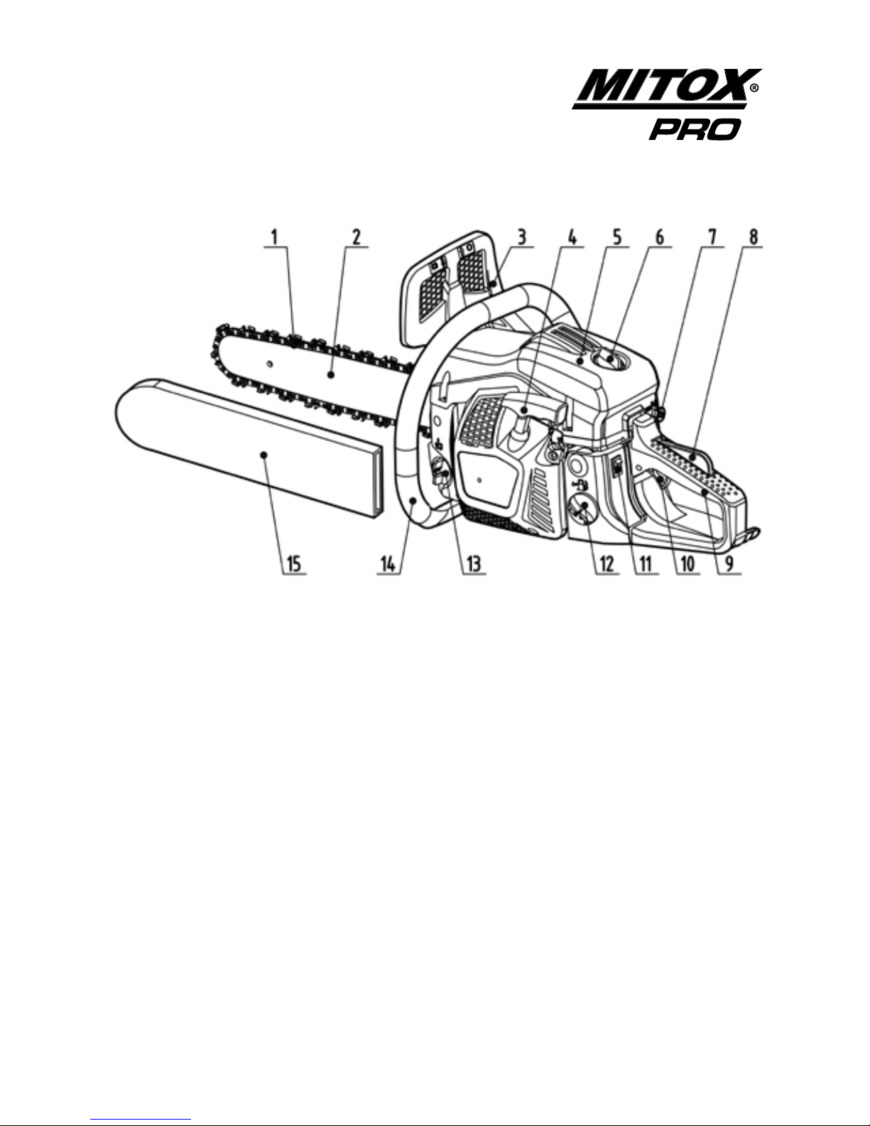
Component Location
1. Saw chain
2. Guide bar
3. Front hand guard
4. Starter handle
5. Air lter cover
6. Lock nut
7. Choke knob
8. Throttle trigger lock lever
9. Rear handle
10. Throttle trigger
11. Engine switch
12. Fuel tank
13. Oil tank
14. Front handle
15. Guide bar scabbard
PRODUCT DESCRIPTION
This Chain Saw is a 2 stroke fast running power tool and is designed to be used in a
domestic application for cutting wood only. Do not cut metal, plastic or any non-wood
materials.
Page 3

CS45 / CS50 / CS56 Chainsaw
3
Original Instructions Version April 12
Safety Precautions
In order to ensure proper and safe operation of your chain saw:-
• Read this Owner/Operator Manual carefully. Be sure you understand how to operate this unit properly
before you use it. Failure to do so could result in serious injury.
• Keep this manual handy so that you may refer to it later whenever any questions arise. Also note that you
are able to contact the dealer from whom you purchased the product for assistance, in the event that you
have any questions which cannot be answered in the manual.
• Always include this manual when selling, lending, or otherwise transferring the ownership of this product.
• This product is a 2 stroke fast running power tool and has been designed to be used as a chain saw for
cutting wood and it should never be used for any other purpose, doing so could result in unforeseen
accidents and injuries occurring.
• This product is equipped with extremely sharp blades, and when used incorrectly these blades can be
dangerous.
For this reason, you should never use this chain saw when under the inuence of alcohol, suering
from exhaustion or lack of sleep, suering from drowsiness as a result of having taken medicine,
or at any other time when a possibility exists that your judgment might be impaired or that you
might not be able to operate the chain saw properly and in a safe manner. Never allow children or
anyone unable to fully understand the directions given in this manual to use this chain saw.
• Avoid running the engine indoors. The exhaust gases contain harmful carbon monoxide.
• Never use the chain saw in conditions as described below:
1. When the ground is slippery or when other conditions exist which might make it dicult to maintain a
steady posture while using the chain saw.
2. At night, at times of heavy fog, or at any other times when your eld of vision is limited and it would be
dicult to gain a clear view of the area where the chain saw is to be used.
3. In heavy rain, during lightning storms, at times of strong or gale-force winds, or at any other times when
weather conditions might make it unsafe to use this product.
• When using this chain saw for the rst time, before beginning actual work, take the chain saw to a wide,
clear, open space, start the engine, and practice handling the chain saw until you are sure that you will be
able to handle it properly in actual operation.
Page 4

CS45 / CS50 / CS56 Chainsaw
4
Original Instructions Version April 12
• Lack of sleep, tiredness, or physical exhaustion results in lower attention spans, and this in turn can lead to
accidents and injury. When planning your work schedule, allow plenty of time to perform the work and allow
plenty of time for rest. Limit the amount of time you continuously use the chain saw to 30~40 minutes per
session, and take 10~20 minutes of rest between work sessions. Also try to keep the total amount of work
performed in a single day to 2 hours.
Do not operate the chain saw in a tree unless specially trained to do so
Work gear and clothing
• When using your chain saw, always wear strong, durable, work clothing; shirts should be long-sleeved and
trousers should be full-length.
Always
• Wear a helmet and face protector.
• Wear ear protectors.
• Wear gloves with saw protection.
• Wear trousers with saw protection.
• Wear boots with saw protection, steel toe caps with non slip sole.
Warnings regarding handling of fuel
• The engine of the chain saw is designed to run on a fuel oil mixture. This fuel is highly ammable, and you
should never store cans of fuel or rell the tank of the chain saw in any place where there is a source of heat
or re which might ignite the fuel.
• Do not smoke whilst operating the chain saw or relling, keep lit cigarettes away from the chain saw at all
times.
• When relling the tank always turn o the engine rst and carefully make sure that there are no sparks or
open ames anywhere nearby before refuelling.
• If any fuel spillage occurs during refuelling, use a dry rag to wipe any fuel which has been spilled onto the
chain saw before starting the engine.
• After refuelling, screw the fuel cap back tightly onto the fuel tank and then carry the chain saw to a spot 3
metres or more away from where it was refuelled before starting the engine.
Page 5

CS45 / CS50 / CS56 Chainsaw
5
Original Instructions Version April 12
Before using your chain saw
• Before beginning work, carefully check around the area and remove any obstacles and clear a retreat path
from falling trees.
• The area within a perimeter of 15 metres of the person using the chain saw should be considered a
hazardous area into which no one should enter while the chain saw is being used, and when necessary mark
with a warning rope, warning signs, or other forms of warning. When work is to be performed simultaneously
by two or more operators, care should also be taken to constantly look around to check the presence and
locations of other operators within the work area so as to maintain a safe distance between each person.
• Before beginning work, each component of the chain saw should be checked to make sure that it is in
proper working order and to make sure that there are no loose screws or bolts, fuel leaks, ruptures, dents, or
any other problems which might interfere with safe operation. Be especially careful to check that there is no
damage to the blades or chain brake.
• Never use the chain saw when the blades/chain are excessively worn or when any sort of damage has
occurred to the cutting mechanism.
Keep all parts of your body away from the saw chain when the engine is running.
Page 6

CS45 / CS50 / CS56 Chainsaw
6
Original Instructions Version April 12
Avoid Noise Problems
Check and follow the local regulations for sound level and hours of operation for garden machinery.
• In general, operate chain saws between 8 am, and 5 pm on week days and 9 am to 5 pm weekends. Avoid
using the chain saw late at night and/or early in the morning.
Safety when using your chain saw
• When using your chain saw, grip the handles rmly with both hands, place your feet slightly apart so your
weight is distributed evenly across both legs, and always be sure to maintain a steady, even posture while
working. Do not use on ladders or if the ground surface is slippery or uneven. Never attempt to cut directly
overhead or with one hand.
• Maintain full engine speed when cutting.
• Never allow other persons to come within the work area as doing so might expose them to danger.
• If a branch or other object gets caught in the blades during operation, always turn o the engine before
removing the object.
• To protect yourself against injury from falling branches, wear the required safety equipment.
• Keep operation area clear of all persons, particularly small children and pets. Injury may result from ying
debris.
• Never touch the spark plug or plug HT cable while the engine is in operation, doing so may result in an
electrical shock.
• Never touch the muer, spark plug, or other parts of the engine while the engine is in operation or
immediately after shutting down the engine. These parts reach high temperatures during operation and
doing so could result in serious burns.
• When you nish cutting in one location and wish to continue work in another area, turn o the engine,
place the protective cover over the blades, and turn the chain saw so that the blades face away from your
body before carrying it to the new location.
• Always remove fuel from the fuel tank before transportation to prevent fuel spillage.
• When not in use never leave the chain saw exposed to direct sunlight as this can heat the fuel tank and may
cause a discharge of fuel, and ood the engine.
Page 7

CS45 / CS50 / CS56 Chainsaw
7
Original Instructions Version April 12
Kickback and Safety Precautions
Beware of kickback!
Kickback can occur whenever the tip of the guide bar touches an object
while the saw is operating. Kickback may force the bar up and back towards
the operator with speed!
Beware of pinching!
Pinching the saw along the tip of the guide bar may force the bar back rapidly
toward the operator. Pinching can occur whenever wood closes in around the
moving chain.
Both kickback and pinching may cause you to lose control of the chain saw, which could result in serious
personal injury.
1. Understand kickback and pinching!
2. Keep a rm grip on the chain saw with both hands whenever the engine is running.
A rm grip will help you reduce the aects of kickback and pinching as well as maintain control of
the machine.
3. Cut at high engine speeds.
4. Follow the manufacturer’s instructions for sharpening and maintaining the chain.
5. Use only genuine spare parts.
Page 8

CS45 / CS50 / CS56 Chainsaw
8
Original Instructions Version April 12
Safety Symbols
Taking care of warning labels
Always keep warning labels clean and free of scratches, which might make them illegible or dicult to read.
If the warning labels provided with your chain saw become damaged, peel o, or otherwise become illegible
or dicult to read, order new labels from the authorised servicing dealer and replace the damaged labels.
When applying new labels, rst wipe away any dirt and dry the surface before applying the new label in the
same place as the original label.
Warning, Danger, Caution
Read the documentation and
safety instructions which are
provided in this user manual.
When operating this
machine, use protective
equipment such as goggles,
helmet and ear defenders,
and safety clothing.
Use the chain saw with two
hands.
Beware: keep hands and feet
away from moving parts.
Always keep a safe distance
from the cutting parts.
Beware of objects being
thrown from the operating
zone.
Warning! Danger of kickback
Directive 2000-14/CE.
Guaranteed noise levels.
Danger: risk of intoxication.
Danger: risk of re or
explosion.
Hot surface, risk of burn.
Page 9
CS45 / CS50 / CS56 Chainsaw
9
Original Instructions Version April 12
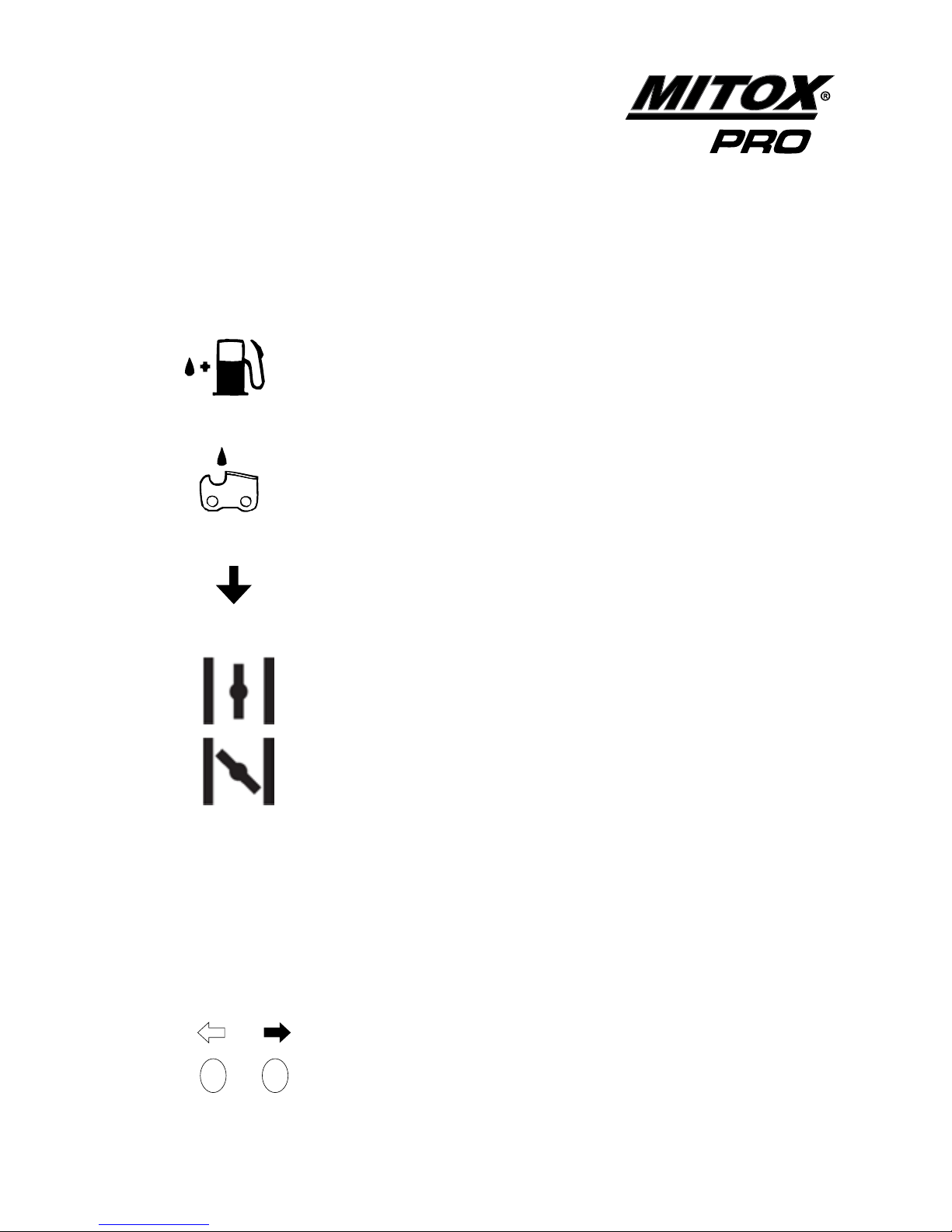
Explanation of Symbols on the Machine
STOP
For safe operation and maintenance, symbols are carved in relief on the
machine.
Fuel tank 2 stroke mix
Position: Fuel cap
Chain oil tank
Position: oil cap
Stop Switch
Setting the switch to the “O” position, the engine stops immediately.
Position: Rear-left of the unit
Starting mode when the engine is hot.
Position: Upper-right of the air cleaner cover.
Starting mode when the engine is cold.
The screw under the “H” stamp is The High-speed adjustment screw.
Position: Left side
The screw under the “L” stamp is The Slow-speed adjustment screw.
Position: Left side
The screw at the left of the “T” stamp is the idle adjustment screw.
Position: Left side
Shows the directions that the chain brake is Released (white arrow) and
Activated (black arrow).
Position: Front of the chain cover
)
)
)
)
)
H
L
T
Page 10
CS45 / CS50 / CS56 Chainsaw
10
Original Instructions Version April 12
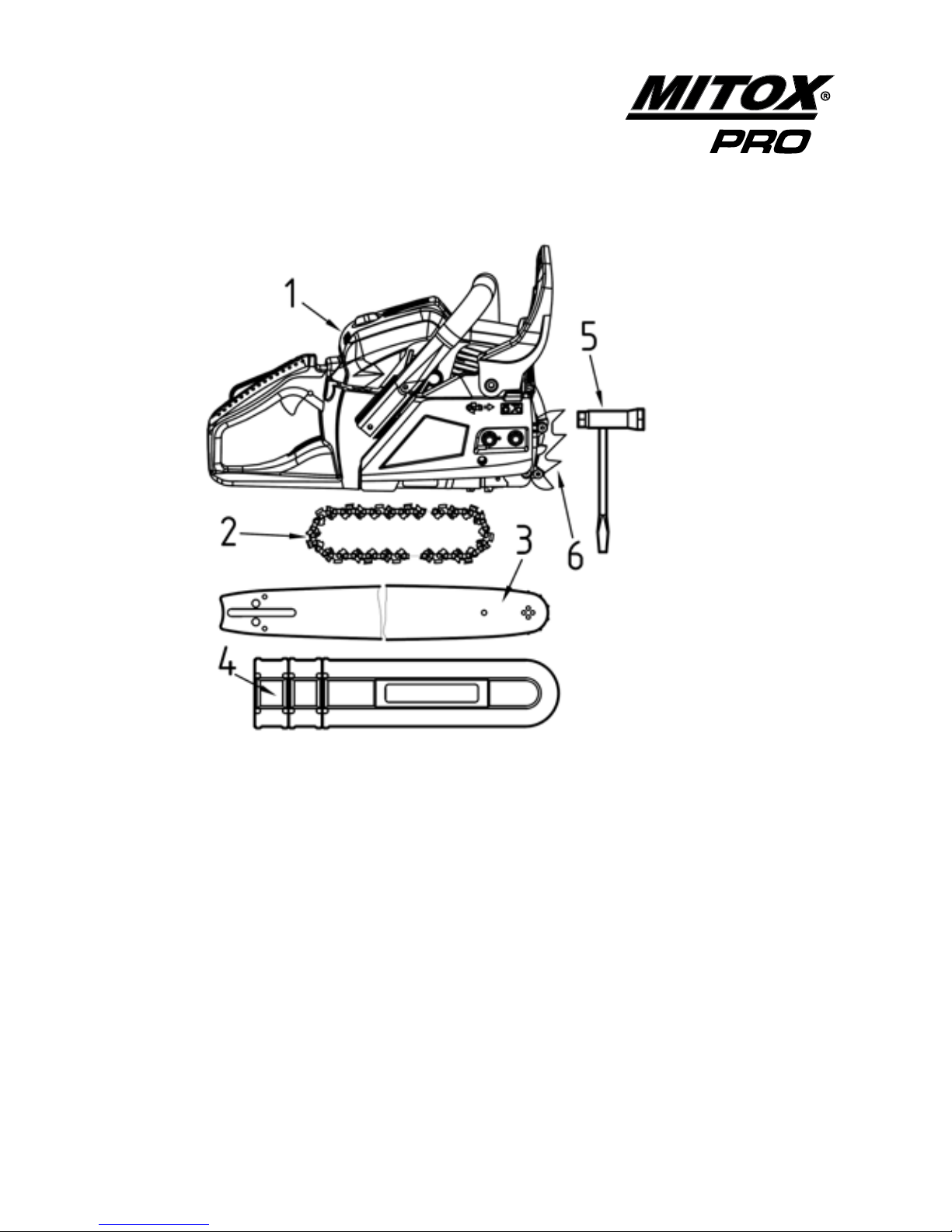
In the Box
A standard saw unit package contains the items as illustrated.
1) Power unit
2) Saw chain
3) Guide bar
4) Bar protector
5) Plug wrench
6) Spike and mounting screws, dependent on model.
Not pictured
7) Owner’s manual.
Page 11
CS45 / CS50 / CS56 Chainsaw
11
Original Instructions Version April 12
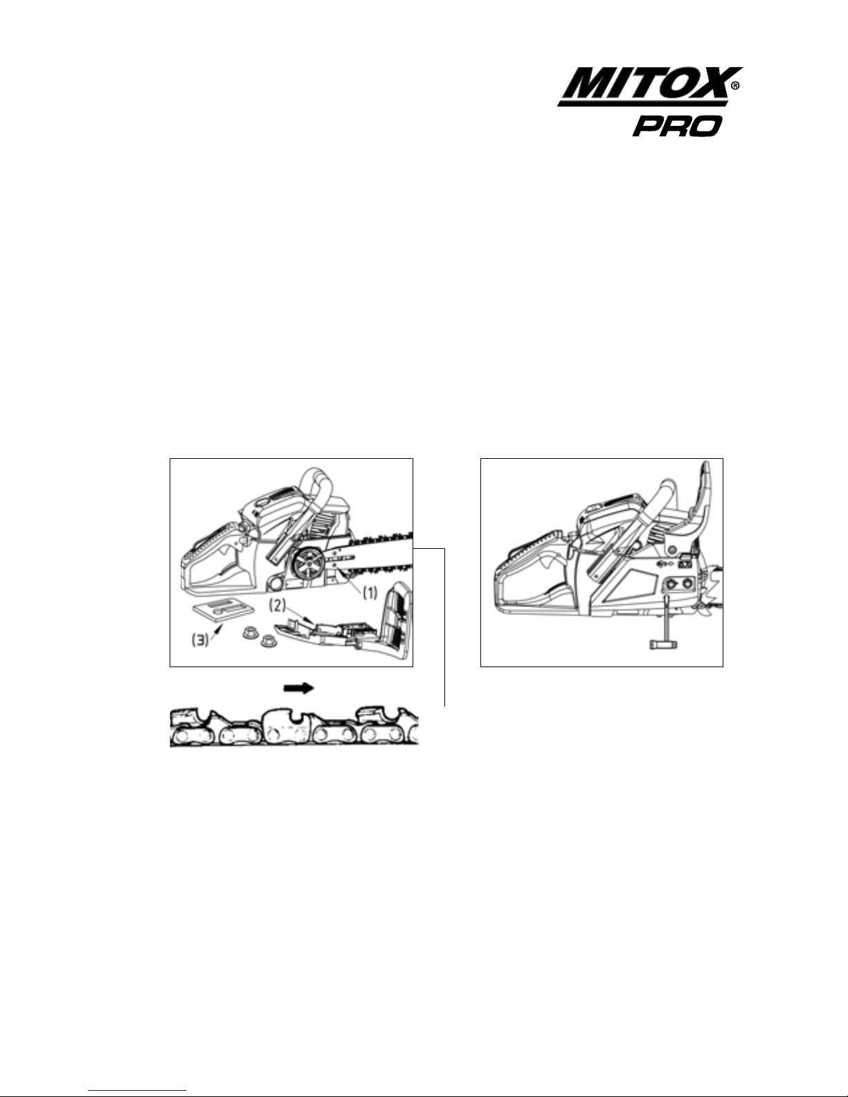
Installing the Guide Bar and Chain
Open the box and install the guide bar and the saw chain on the power unit as follows:
The saw chain has very sharp edges. Use thick protective gloves for safety.
1. Pull the guard towards the front handle to check that the chain brake is not on.
2. Loosen the nuts and remove the chain cover.
3. Install the spike to the power unit (dependent on model).
4. Remove and discard the plastic packer (3) located on the bar studs.
5 . Fit the guide bar over the bar bolts.
Figure 1. Figure 2.
Chain Direction
6. Figure 1 Fit the chain to the drive sprocket and while tting the saw chain around the guide bar,
adjust the position of the chain tensioner located in the side cover (2) to t into the hole (1) in the
guide bar.
7. Fit the chain cover to the power unit and fasten the nuts nger tight.
8. Figure 2 While holding up the tip of the bar, adjust the chain tension by turning the tensioner
screw until the chain does not sag from the underside of the guide bar.
9. Tighten the bar nuts securely with the bar held up to 12/15N.M, then check the chain for smooth
rotation and proper tension while moving the chain by hand.
Note: A new chain will expand in length at the beginning of use. Check and readjust the tension
frequently, as a loose chain can easily derail or cause rapid wear to itself and the guide bar.
Page 12

CS45 / CS50 / CS56 Chainsaw
12
Original Instructions Version April 12
Before starting the engine
• Carefully check the area to make sure that no obstacles exist within a perimeter of 5 metres around the
chain saw before starting the engine.
• When starting the engine, place the body of the chain saw onto the ground in a at clear area and hold it
rmly in place to ensure that neither the blades nor the throttle come into contact with any obstacles when
the engine starts up.
• After starting the engine, make sure that the blades stop moving when the throttle trigger is released (idle).
If the blades continue to move when the engine is at idle, adjust the idle screw on the carburettor to a point
where the blades stop moving, if this cannot be achieved, turn o the engine and take the chain saw to your
authorised servicing dealer for adjustment.
• The chain brake must be engaged before starting the chainsaw. Apply the chain brake by pushing the front
hand guard forwards. (see page 14)
Fuel & Chain Oil
WARNING
• Fuel is very ammable. Do not smoke or bring any ame or sparks near fuel. Always stop the
engine and allow it cool before refuelling. Refuel outdoors on bare ground, restart engine at least
3m away from the refuelling stop.
FUEL MIX TWO-STROKE
The engine is lubricated by oil mixed into petrol. Prepare a mixture of unleaded petrol and only use semi-
synthetic two-stroke oil that meets the specications of: API TC, ISO-L-EGC, JASO FC (Low Smoke) oil.
Recommended mixing ratio is 40:1.
Use fresh, unleaded petrol (95 RON) and semi-synthetic oil specially made for high performance two-stroke
engines. Mix in a ratio of 40 parts petrol to 1 part of oil.
Using two-stroke oil specially made for two-stroke engines will reduce the formation of ash and carbon
deposits in the spark plug, piston, muer and cylinder as well as reducing emissions of harmful exhaust
gases. Lubrication will be maximized and the engine life extended.
40 : 1
Page 13

CS45 / CS50 / CS56 Chainsaw
13
Original Instructions Version April 12
It is important to only use good quality, fresh petrol and oil. The two-stroke fuel mixture should be
used within four weeks.
IMPORTANT
Stored two-stroke fuel may separate during storage, always shake fuel container before each use.
DO NOT USE:
• Fuel containing no oil (raw petrol) will cause the engine to become overheated and severe damage will
occur which is not covered by warranty
Fuelling
WARNING
1. Stop the engine before refuelling the unit, agitate the mixed two-stroke mixture in the
container.
2. Move at least 3 metres away from the fuelling point before starting the engine.
3. Mixed fuel which have been stored for a period of one month or more may damage/
block the carburettor resulting in the engine failing to start.
4. In the case of storing the product for a long period of time, empty the fuel tank. Next,
run the engine to empty the carburettor of fuel.
FUELLING THE CHAINSAW
1. Shake the fuel container to thoroughly mix the two-stroke oil and petrol mix.
2. Clean around the fuel cap before removing.
3. Pour 40:1 two-stroke fuel into the fuel tank with a ltered funnel, up to 80% of the fuel tanks
capacity.
4. Replace the fuel cap and tighten securely. Spilled fuel must be wiped away from the chain saw
before starting the engine.
CHAIN OIL
Use only special anti ing chain oil grade SAE30. Fill the chain oil tank every time you ll the fuel tank.
Note: Do not use waste or regenerated oil that can cause damage to the oil pump.
Page 14
CS45 / CS50 / CS56 Chainsaw
14
Original Instructions Version April 12
Chain Brake
This machine is equipped with an automatic brake to stop the saw chain rotation upon the occurrence of
kickback during saw cutting. The brake is automatically operated by inertial force, which acts on the weight
tted inside the front guard. The brake can also be operated manually by pushing the front guard forward
towards the guide bar.
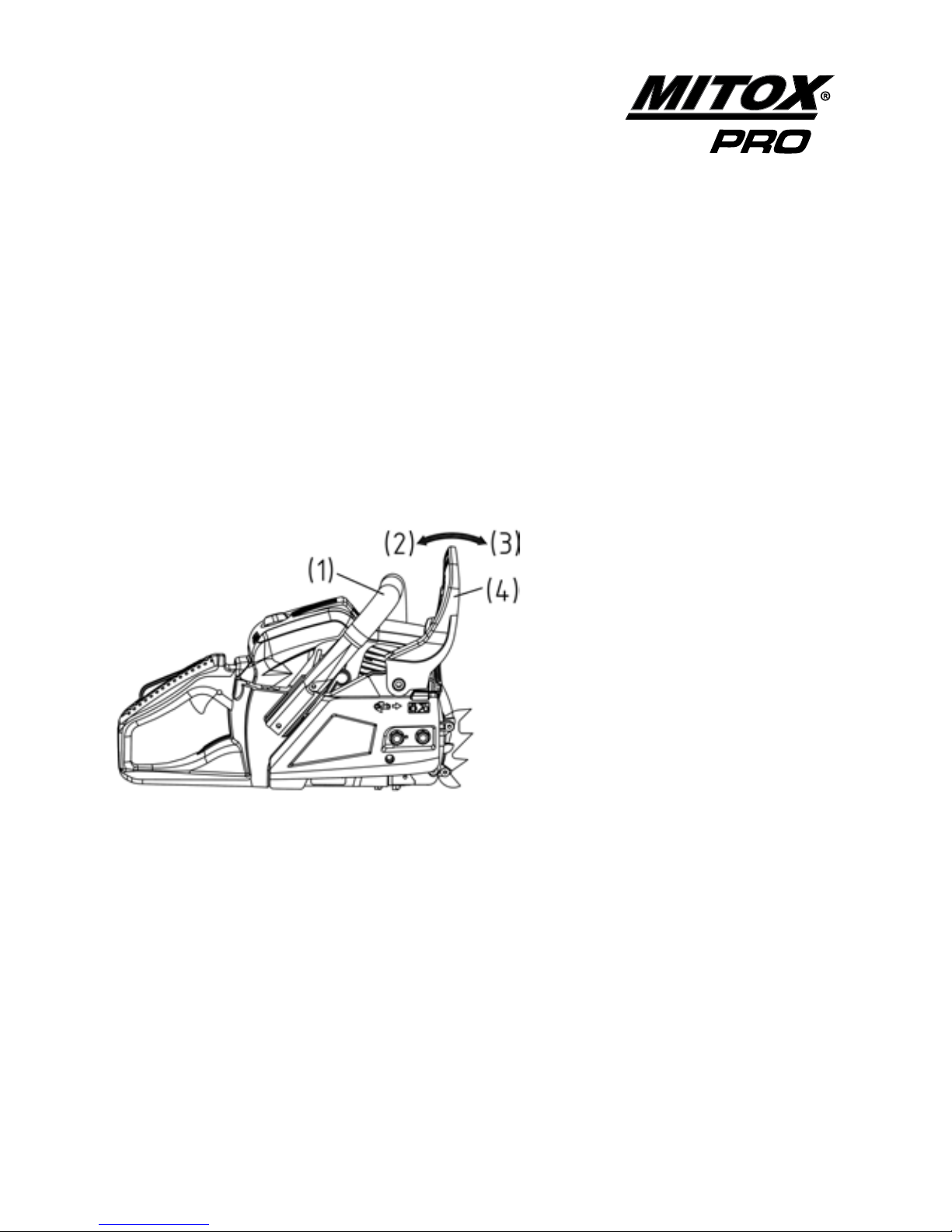
To release the brake, pull back the front guard (4) toward the front handle (1) until a “click” sound is heard (2).
How to check:
You must check the chain brake operation before each usage by running the saw at full throttle for 1-2
seconds and pushing the front hand guard (4) forward (3).
The chain should stop immediately with the engine at full speed.
If the chain is slow to stop or does not stop, replace the brake band and clutch drum before use.
Before proceeding to your job, it is recommended to rst practice sawing easy logs. This also helps you get
accustomed to your unit.
Always follow the safety regulations:
The chain saw must only be used for cutting wood. It is forbidden to cut other types of material. Vibrations
and kick-back vary with dierent materials and the requirements of the safety regulations would not be met.
Do not use the chain saw as a lever for lifting, moving or splitting objects.
The saw should cut easily without force. Apply only light pressure while running the engine at full throttle.
When the saw chain is caught in the cut, do not attempt to pull it out by force, but use a wedge or a lever to
open the way.
Page 15

CS45 / CS50 / CS56 Chainsaw
15
Original Instructions Version April 12
Kickback Safety Precautions
Kickback may occur when the nose or tip of the guide bar touches an object, or when the wood closes in
and pinches the saw chain in the cut. Top contact in some cases may cause a lightning fast reverse reaction,
kicking the guide bar up and back towards the operator. Pinching the saw chain along the top of the guide
bar may push the guide bar rapidly back towards the operator. Either of these reactions may cause you to
lose control of the saw which could result in serious personal injury.
Do not rely exclusively on the safety devices built into your saw. As a chain saw user you should take several
steps to keep cutting jobs free from accident or injury.
1. With a basic understanding of kickback you can reduce or eliminate the element of surprise.
Sudden surprise contributes to accidents.
2. Keep a good grip on the saw with both hands, the right hand on the rear handle, and the left
hand on the front handle, when the engine is running. Use a rm grip with thumbs and ngers
encircling the chain saw handles. A rm grip will help you reduce kickback and maintain control
of the saw.
3. Make certain that the area in which you are cutting is free from obstructions. Do not let the nose
of the guide bar contact a log, branch, or any other obstruction which could be hit while you are
operating the saw.
4. Cut at high engine speeds.
5. Do not overreach or cut above shoulder height.
6. Follow manufacturers sharpening and maintenance instructions for saw chain.
7. Only use replacement bars and chains specied by the manufacturer or the equivalent.
It is important to maintain the proper chain tension. Rapid wear of the guide bar or the chain
coming o can be caused by improper tension, especially when using a new chain.
Page 16

CS45 / CS50 / CS56 Chainsaw
16
Original Instructions Version April 12
Operating the Engine
1. Fill fuel (2) and chain oil (1) tanks respectively, and tighten the
caps securely.
2. Set the switch (3) to “I” position.
3. Press the primer button (4) 6 times.
4. Pull out the choke knob (5). The choke will close and the throttle
will be set in the starting position.
5. Push in the decompressor valve (6).
6. Apply the chain brake by pushing the front hand guard (7) forwards.
7. Place the saw on the ground, grip the front handle with your left hand,
place your right foot through the rear handle. Pull the starter handle
with your right hand.
Caution: do not pull the starter cord all the way out and do not let
go of the starter handle if the cord is extended, this can damage
the starter mechanism.
8. When the engine has tried to re, push in the choke knob (5) and then pull the starter handle
again to start the engine.
9. As soon as the engine is running, pull the throttle lever slightly to reset the throttle control to idle.
This must be done as soon as the engine has started to avoid unneccessary wear on the clutch.
NOTE: Disengage the chain brake by pulling the front hand guard towards the front
handle prior to cutting.
6
Page 17

CS45 / CS50 / CS56 Chainsaw
17
Original Instructions Version April 12
Hot engine
1. Set the switch (3) to “I” position.
2. Pull out the choke knob (5), then push the choke knob back in, this will set the throttle to the hot
start position.
3. Push in the decompressor valve (6).
4. Apply the chain brake by pushing the front hand guard (7) forwards.
5. Pull the starter handle until the engine runs.
6. As soon as the engine is running, pull the throttle lever slightly to reset the throttle control to idle.
This must be done as soon as the engine has started to avoid unneccessary wear on the clutch.
NOTE: Disengage the chain brake by pulling the front hand guard towards the front
handle prior to cutting.
Running In
During the rst ten hours of work, avoid running the engine at maximum speed for a prolonged period until
all the components have bedded in. After the engine has been run in, it will reach its maximum power.
After two hours of work, check that all nuts and screws are securely fastened and tighten if necessary.
Stopping Engine
1. Release the throttle lever and allow the engine to run at idle for half a minute.
2. Shift the ignition switch to the STOP position (“0”).
NOTE: Except for an emergency, avoid stopping the engine while at full throttle.
6
Page 18

CS45 / CS50 / CS56 Chainsaw
18
Original Instructions Version April 12
Checking the Oil Supply
After starting the engine, run the chain at medium speed
and see if chain oil is sprayed as shown in the gure.
WARNING
• This chain saw is equipped with very sharp blades, and when used incorrectly the blades can
be extremely dangerous. Improper handling can cause accidents which may in turn lead to
serious injury or death. For this reason, you should always be careful to adhere to the following
instructions when using your chain saw.
• Never hold the chain saw in a way in which the blades are pointed towards someone else.
• Never allow the blades to come into proximity with your body while the engine of the chain saw is in
operation.
• Always turn o the engine before adjusting the blades, removing branches which have become stuck in the
blades, or at any other time when coming into close proximity with the blades.
• Always wear work gloves made of leather when adjusting the chain saw.
• Always place the blade cover provided with the chain saw over the blades when not in use.
• Falling branches may fall onto the operators face or into the eyes, resulting in injuries, scratches,
and cuts, and for this reason you should always wear a helmet and face protector when using your
chain saw
Transportation
• Never transport the chain saw with the engine running. An engine that is running could be accidently
accelerated causing the blade to engage.
• Make sure the blade safety guards are in place when transporting the chain saw.
• When carrying by hand, the cutting head should be pointing backwards.
• Ensure the chain saw is secure when transporting in a vehicle and the tank is drained of fuel.
Page 19

CS45 / CS50 / CS56 Chainsaw
19
Original Instructions Version April 12
Care and Maintenance of Your Chain Saw
• In order to maintain your chain saw in good working order, perform the maintenance and checking
operations described in this manual at regular intervals. In the event that any part needs to be replaced,
please contact the nearest authorised service dealer for assistance.
• Always turn o the engine before performing any maintenance or checking procedures.
• When sharpening, removing, or reattaching the blades, be sure to wear thick, sturdy gloves and use only
appropriate tools and equipment to prevent injury.
• When replacing blades or any other parts, be sure to use only genuine spare parts and approved lubricants.
Maintenance
IMPORTANT
• After every use, check that all nuts, bolts and screws are securely fastened and tighten if
necessary.
• In the event of an accident, breakdown or blockage, ensure the engine is turned o before any
work is carried out to rectify this.
• Make sure the engine has stopped and is cool before performing any service to the machine.
Contact with moving cutting head or hot muer may result in a personal injury. Always wear
heavy-duty gloves when handling the blades.
Maintenance After Each Use
Air lter
Dust on the air cleaner surface can be removed by tapping a corner of the cleaner against a hard surface.
To clean dirt in the meshes, split the cleaner into halves and brush o the dust lightly or wash in non-
inammable solvent, or replace the air lter.
To assemble the cleaner halves, press until it clicks.
Page 20

CS45 / CS50 / CS56 Chainsaw
20
Original Instructions Version April 12
Maintenance After Each Use
Oiling port
Dismount the guide bar and check the oiling port (1) for clogging.
Guide bar
When the guide bar is dismounted, remove sawdust from the bar groove and the oiling port.
Grease the nose sprocket with a sprocket grease gun (Oregon part number 21939)
1. Guide bar groove
2. Oil hole
3. Drive sprocket
4. Grease point
Others
Check for fuel leakage and loose fastenings and damage to major parts, especially handle joints and guide
bar mounting. If any defects are found, make sure to have them repaired before operating the saw again.
Check for cracks and for excessive wear interfering with the chain drive. If the wear is considerable, replace it
with a new one. Never t a new chain on a worn sprocket, or a worn chain on a new sprocket.
Page 21

CS45 / CS50 / CS56 Chainsaw
21
Original Instructions Version April 12
Periodical Service Points
Cylinder Fins
Dust clogging between the cylinder ns will cause
overheating of the engine.
Periodically check and clean the cylinder ns after removing
the cylinder cover.
When installing the cylinder cover, make sure that switch
wires and grommets are tted correctly.
Fuel lter
Using a wire hook, take out the lter (1) from the ller port.
Disassemble the lter and clean with petrol, or replace with
a new one if needed.
Spark plug
Clean the electrodes with a wire brush and reset the gap to
0.65 mm as necessary.
Plug type: NGK: BPRM7A
Sprocket
Check for cracks and for excessive wear interfering with the
chain drive. If the wear is considerable, replace it with a new
a one. Never t a new chain on a worn sprocket, or a worn
chain on a new sprocket.
Page 22

CS45 / CS50 / CS56 Chainsaw
22
Original Instructions Version April 12
Adjusting Oil Flow Rate
Never ll the oil reservoir or adjust the oiler with the engine running.
An increase in bar oil ow rate will speed oil consumption, requiring more frequent checks on the oil
reservoir. To ensure sucient lubrication, it may be necessary to check the oil level more frequently than at
fuel tank rells. The guide bar and chain are lubricated automatically by a pump that operates whenever
the chain rotates. The pump is set at the factory to deliver a minimum ow rate, but it can be adjusted in the
eld. A temporary increase in oil ow is often desirable when cutting hardwood.
Adjust the pump as follows:
1. Stop the engine and make sure the stop switch is in the OFF position.
2. Place the unit on its side with the sprocket side and chain brake assembly facing up.
3. With a screwdriver, push in on the oil ow rate adjusting screw and turn in the desired
direction: Clockwise-decrease lubrication / Counter clockwise-increase lubrication.
Page 23

CS45 / CS50 / CS56 Chainsaw
23
Original Instructions Version April 12
Saw Chain Sharpening
The chain needs to be sharpened when:
1. Sawdust becomes powder-like. 4. You need extra force to saw with.
2. The cut path does not go straight. 5. Vibration increases.
3. Fuel consumption increases.
Be sure to wear safety gloves.
• Clamp chain saw guide bar in a vice to secure.
• Sharpen chain with a 3/16 (4.8mm) le and holder (Oregon part number 18228) / Sharpening kit
(Oregon part no 90407)
• Place your le on the cutter and push straight forward. Keep the le position.
• After every cutter has been set, check the depth gauge and le it to the proper level.
• Make sure every cutter has the same length and edge angles as illustrated.
Page 24

CS45 / CS50 / CS56 Chainsaw
24
Original Instructions Version April 12
Adjusting the Carburettor
The carburettor has been factory adjusted, but may require ne tuning due to a change in operating
conditions. Before adjusting the carburettor, make sure that the provided air/fuel lters are clean and the fuel
properly mixed.
When adjusting, take the following steps:
Stop the engine and screw in both the H and L needles until they stop. Never force them. Then set them
back the initial number of turns as shown below.
H needle: 2+ or -¼
L needle: 2+ or -¼
1. Start the engine and allow it to warm up at half-throttle.
2. Turn the L needle (2) slowly to nd a position where
idling speed is at maximum, then set the needle back
a quarter (1/4) turn counter clockwise.
3. Turn the idle adjusting screw T (1) counter clockwise so
that the saw chain does not turn. If the idling speed is
too slow, turn the screw clockwise.
4. To verify the low speed you should be able to pull the
throttle in all the way and the engine should not die,
if it tries to die, open the L jet (2) slightly and re-adjust
idle if necessary.
5. Set the engine to full throttle, the H jet (3) is turned clockwise to reduce fuel, as the fuel mixture is
leaned out, the saw will run faster until it sounds as if it is screaming, at this point, turn the high
speed screw counter clockwise by quarter (1/4) turn to allow more fuel in.
A 2-cycle engine relies on the fuel mixture to cool the engine; a lean engine will run fast but can
overheat and may cause severe damage to the engine.
Page 25

CS45 / CS50 / CS56 Chainsaw
25
Original Instructions Version April 12
Service Schedule
Troubleshooting
Power loss or engine stopping.
- Check that the fuel tank is not empty.
- The mixture does not reach the carburettor. Change the fuel lter in the fuel tank.
- There is water in the mixture. Drain then clean the fuel system .
- The air lter is dirty. Clean the air lter.
- There are carbon deposits in the cylinder exhaust pipe or the muer. Clean or change muer.
- Spark plug is worn. Replace spark plug.
Component Procedure
Before
Use
Every
25
Hours
Every
50
Hours
Every
100
Hours
Note
Fuel Leaks / Fuel
Spillage
Wipe Out
•
Fuel Tank. Fuel Filter Inspect / Clean • • Replace if Neccessary
Idle Adjusting
Screw
See Adjusting
Carburettor
•
Adjust if Neccessary
Spark Plug Clean and
Readjust Plug Gap •
Gap 0.025in (0.6-
0.7mm) Replace if
Neccessary
Cylinder Fins, Intake
Air Cooling Vent
Clean
•
Muer, Spark
Arrestor, Cylinder
Exhaust Port
Clean
•
Throttle Lever,
Ignition Switch
Check Operation
•
Air Filter Clean •
Screws, Nuts, Bolts Tighten / Replace
• •
Except Adjusting
Screws
Oiling Port Clean •
Guide Bar Clean •
Sprocket Inspect / Replace •
Saw Chain Inspect / Sharpen •
Page 26

CS45 / CS50 / CS56 Chainsaw
26
Original Instructions Version April 12
Specications
Power unit
Displacement
CS46……………………………………………………………………………………………………45.02cc
CS50…………………………………………………………………………………………………49.30cc
CS56…………………………………………………………………………………………………56.00cc
Maximum engine power
CS46……………………………………………………………………………………………………1.70kW
CS50………………………………………………………………………………………………….2.10kW
CS56…………………………………………………………………………………………………2.35kW
Fuel………………………………………………. …………Mixture (Unleaded Gasoline 40: two-cycle oil 1)
Fuel tank capacity………………………………………………………………………………………550ml
Chain oil……………………………………………………………………………………….Anti-Fling SAE-30
Oil tank capacity…………………………………………………………………………………………260ml
Carburettor……………………………………………………………………………………Diaphragm type
Idling speed…………………………………………………………………………………………3200r/min
Maximum speed with cutting attachment………………………………………………………11000r/min
Ignition system……………………………………………………………C.D.I. with timing advance function
Spark plug………………………………………………NHSP LD L8RTF/ CHAMPION RCJ7Y/ NGK BPMR7A
Oil feeding system…………………………………………………Mechanical plunger pump with adjuster
Sprocket Teeth x Pitch
CS46, CS50 & CS56…………………………………………………………………………………7T×0.325in
Dimensions (L x W x H)…………………………………………………………………410×250×285(mm)
Dry weight
CS45 (with guide bar and chain, empty tanks): ………………………………………………………………6.25kg
CS50 (with guide bar and chain, empty tanks): ……………………………………………………………6.30kg
CS56 (with guide bar and chain, empty tanks): ………………………………………………………….6.55kg
Page 27

CS45 / CS50 / CS56 Chainsaw
27
Original Instructions Version April 12
Cutting gear
Type……………………………………………………………………………………………. Sprocket nose
Size
CS46…………………………………………………………………………………………………..16in
CS50………………………………………………………………………………………..……………… 18in
CS56………………………………………………………………………………………..…… …………20in
Saw chain
Type
CS46 / CS50 / CS56………………………………………………………………………………Oregon 21BPX
Pitch
CS46 / CS50 / CS56………………………………………………………………………………………..0.325in
Gauge
CS46 / CS50 / CS56………………………………………………………………………………………..0.058in
Page 28

CS45 / CS50 / CS56 Chainsaw
28
Original Instructions Version April 12
CS46 / CS50 / CS56
Parts - Base Unit
Page 29

CS45 / CS50 / CS56 Chainsaw
29
Original Instructions Version April 12
CS46 / CS50 / CS56
Parts - Base Unit
ID PART NUMBER DESCRIPTION CS46 CS50 CS56 QTY
1 MITCS4600.04.00-00 CHAINBRAKE ASSEMBLY Y 1
1 MITCS5000.04.00-00 CHAINBRAKE ASSEMBLY Y Y 1
2 MIYD38-3.04.00-16 SCREW M5X40 Y Y Y 1
3 MIYD38-3.04.00-13 SLEEVE Y Y Y 1
4 MIYD38-3.04.00-12 SLEEVE Y Y Y 1
5 MIGB/T119.2 3X14 PIN 3X14 Y Y Y 1
6 MIYD45.04.00-24 TENSIONER SCREW Y Y Y 1
7 MIYD45.04.00-25 TENSIONER PAWL Y Y Y 1
8 MIYD45.04.00-11 TENSIONER COVER PLATE Y Y Y 1
9 MIGB/T845 ST4.2X9.5 TAPPING SCREW ST4.2X9.5 Y Y Y 4
10 MITCS4600.04.00-2 CHAIN BRAKE LEVER Y Y Y 1
11 MIYD38-3.04.00-9 CHAIN BRAKE TORSION SPRING Y Y Y 1
12 MIYD45-3.04.00-13 WASHER 5.2X20X1.2 Y Y Y 1
13 MIGB/T6183.1 M5 NUT M5 Y Y Y 1
14 MIYD38-3.04.00-6 CAP Y Y Y 1
15 MIYD38-3.04.00-5 COMPRESSION SPRING Y Y Y 1
16 MIYD38-3.04.00-4 BLOCK Y Y Y 1
17 MIYD38-3.04.00-3 ACTUATOR Y Y Y 1
18 MIGB/T119.2 3X9 PIN 3X9 Y Y Y 3
19 MIYD45-3.04.00-14 BRAKE CONTROL ROD Y Y Y 1
20 MIYD45-3.04.00-9 BRAKE SPRING Y Y Y 1
21 MIYD45-3.04.00-10 CHAIN BRAKE BAND Y Y Y 1
22 MIYD45.04.00-10 SECONDARY BRAKE SPRING Y Y 1
23 MIYD45-4.04.00-1 BRAKE SPRING COVER PLATE Y Y Y 1
24 MIYD45.04.00-26 TENSIONER GEAR Y Y Y 1
25 MIYD45.01.00-16 CHAIN GUIDE BLOCK Y Y Y 1
27 MITCS4600.04.00-7 DUST SHEILD Y Y Y 1
28 MIYD38-3.04.00-7 SPRING Y Y Y 1
Page 30

CS45 / CS50 / CS56 Chainsaw
30
Original Instructions Version April 12
CS46 / CS50 / CS56
Parts - Base Unit
ID PART NUMBER DESCRIPTION CS46 CS50 CS56 QTY
29 MIYD38-3.04.02-00 BRACKET Y Y Y 1
30 MIGB/T6177.1 M8 NUT M8 Y Y Y 2
31 MITCS4600.05.01-00 AIR FILTER LOCK NUT Y Y Y 1
32 MITCS4600.00.00-1 AIR FILTER COVER Y Y Y 1
33 MIGB/T2672 M5X16 SCREW M5X16 Y Y Y 9
34 MITCS4600.05.00-00 TOP COVER C/W HEAT SHEILD Y Y Y 1
34a MITCS4600.05.00-2 UPPER HEAT SHEILD Y Y Y 1
34b MITCS4600.05.00-3 SIDE HEAT SHEILD Y Y Y 1
35 MITCS4600.00.00-6 ADJUSTER GROMMET Y Y Y 1
36 MITCS4600.02.00-1 GUIDE FLOW COVER Y Y Y 1
37 MITCS4600.02.00-00 RECOIL STARTER ASSEMBLY Y Y Y 1
38 MIGB/T845 ST4.8X14 TAPPING SCREW ST4.8X14 Y Y Y 1
39 MIGB/T96 M5 WASHER M5 Y Y Y 1
40 MIYD45.02.00-2 RECOIL PULLEY Y Y Y 1
41 MIYD45.02.00-5 RECOIL SPRING Y Y Y 1
41a MIYD45.02.00-3 RECOIL SPRING HOLDER Y Y Y 1
42 MIYD38-5.02.00-4 RECOIL HANDLE Y Y Y 1
43 MIYD45.02.00-7 RECOIL ROPE Y Y Y 1
45 MIYD45.03.00-1 ANTI-VIBRATION RUBBER Y Y Y 1
46 MIYD46.03.01-00 FUEL TANK Y Y Y 1
47 MIYD45.03.02-00 ANTI-VIBRATION RUBBER Y Y Y 2
48 MIYD50.00.00-9 SCREW Y Y Y 2
49 MIYD45.00-00-2 DUST COVER Y Y Y 2
50 MIYD38-3.03.02-2 RETAINER Y Y Y 1
53 MITCS4600.03.02-00 FUEL CAP ASSY Y Y Y 1
54 MIYD45.03.00-2 FUEL PIPE Y Y Y 1
55 MIYD45.03.00-15 FUEL CLIP Y Y Y 1
56 MIYD45.03.03-00 FUEL FILTER Y Y Y 1
Page 31

CS45 / CS50 / CS56 Chainsaw
31
Original Instructions Version April 12
CS46 / CS50 / CS56
Parts - Base Unit
ID PART NUMBER DESCRIPTION CS46 CS50 CS56 QTY
57 MIYD04.01.07.07208 BREATHER Y Y Y 1
58 MIYD38-3.03.00-3 BREATHER GROMMET Y Y Y 1
59 MIYD45.03.00-25 THROTTLE ROD Y Y Y 1
60 MIYD45.03.00-11 TRIGGER Y Y Y 1
61 MIYD45.03.00-12 SAFETY TRIGGER SPRING Y Y Y 1
62 MIGB/T119.2 6X22 PIN 6X22 Y Y Y 1
63 MITCS4600.03.04-00 REAR HANDLE GRIP Y Y Y 1
64 MIYD45.03.00-13 SAFETY LOCK TRIGGER Y Y Y 1
65 MIGB/T845 ST4.2X22 TAPPING SCREW ST4.2X22 Y Y Y 1
66 MIYD38-3.01.11.04-00 ON/OFF SWITCH Y Y Y 1
67 MIYD45-2.06.00-00 LOOP HANDLE Y Y Y 1
68 MIGB/T845 ST4.8X16 TAPPING SCREW ST4.8X16 Y Y Y 4
69 MIYD45-4.03.00-11 FUEL PIPE Y Y Y 1
70 MIYD45-4.03.00-13 FUEL PIPE Y Y Y 1
71 MIYD38-3.03.00-4A PRIMER ASSY Y Y Y 1
72 MIOR66EX21BPX CHAIN LOOP - 66EX21BPX Y 1
72 MIOR72EX21BPX CHAIN LOOP - 72EX21BPX Y 1
72 MIOR78EX21BPX CHAIN LOOP - 78EX21BPX Y 1
73 MI168PXBK095 GUIDE BAR - 16" (OREGON) Y 1
73 MI188PXBK095 GUIDE BAR - 18" (OREGON) Y 1
73 MI208PXBK095 GUIDE BAR - 20" (OREGON) Y 1
74 MIBARCOVER-16 BAR COVER - 16" Y 1
74 MIBARCOVER-18 BAR COVER - 18" Y 1
75 MIBARCOVER-20 BAR COVER - 20" Y 1
75 MIYD38-3.08.01-00 PLUG WRENCH Y Y Y 1
76 MIYD45.08.00-1 3/16" FILE Y Y Y 1
Page 32

CS45 / CS50 / CS56 Chainsaw
32
Original Instructions Version April 12
CS46
Parts - Engine Unit
Page 33

CS45 / CS50 / CS56 Chainsaw
33
Original Instructions Version April 12
CS46
Parts - Engine Unit
ID PART NUMBER DESCRIPTION
1 MIYD45.01.02-1 CYLINDER
2 MIGB/T6170 M5 NUT M5
3 MIGB/T93 M5 SPRING WASHER
M5
4 MIGB/T97.1 M5 WASHER M5
5 MIYD45.01.09-1 MUFFLER COVER
PLATE
6 MIYD45.01.09.01-00 MUFFLER
7 MIYD45.01.00-2 MUFFLER GASKET
8 MIYD45.01.00-24 MUFFLER CON-
NECTING SCREW
9 MIGB/T6191 M5X20 SCREW M5X20
10 MISPRCJ6Y SPARK PLUG
(CHAMPION RCJ6Y)
11 MIYD45.01.02-2 AIR INTAKE TUBE
GASKET
12 MIYD45.01.02.01-00 AIR INTAKE TUBE
13 MIGB/T2672 M5X12 SCREW M5X12
14 MIYD45.01.00-17 O-RING
15 MIYD45.01.00-1 CYLINDER GASKET
16 MIYD45.01.03-2 PISTON RING
17 MIYD45.01.03-1 PISTON
18 MIYD45.01.03-4 PISTON PIN CIRCLIP
19 MIYD45.01.03-3 PISTON PIN
20 MIYD45.01.03-5 NEEDLE BEARING
RING
21 MIYD45.01.03.01-00 CRANKSHAFT
22 MIYD45.01.03.02-00 NEEDLE BEARING
11X15X12.5
23 MIGB/T1099 3X3.5X10 SEMI-CIRCULAR KEY
3X3.5X10
ID PART NUMBER DESCRIPTION
24 MIYD45.00.00-4 CONICAL ANTI-
VIRATION SPRING
25 MIYD45.00.00-3 ANTI-VIBRATION
SPRING BASE
26 MIGB/T845 ST4.8X16 TAPPING SCREW
ST4.8X16
27 MIYD45.00.00.01-00 CHAIN CATCHER
28 MIGB/T2672 M5X16 SCREW M5X16
29 MIYD45.01.01.02-2 BREATHER JET
30 MIYD45.01.01.02-3 CIRCLIP
31 MIYD45.01.00-22 SPONGE BREATHER
32 MIYD45.01.00-21 FELLING DOG
33 MIGB/T2672 M5X10 SCREW M5X10
34 MIYD45.01.00.04-2 OIL FILTER SCREEN
35 MIYD45.01.00.04-1 OIL FILTER
36 MIYD45.01.00-12 OIL TUBE
37 MIGB/T2672 M4X14 SCREW M4X14
38 MIYD45.01.15-00 OIL PUMP
39 MIYD45.01.00-23 SPONGE
40 MIYD45.01.00-13 OIL OUTLET PIPE
41 MIYD45.01.00-16 CHAIN GUIDE
BLOCK
42 MIGB/T900 M8x26-8.8 DOUBLE-SCREW
BOLT AYM8M8X26-8
43 MIYD45.01.13.01-00 CLUTCH ASSEMBLY
46 MIYD45.01.13.01-3 CLUTCH SPRING
47 MIYD45.01.00-19 CLUTCH ADJUST-
ING WASHER
48 MIYD45.01.00.10-00 NEEDLE BEARING
12X15X14.5
49 MIYD45.01.13-1 CLUTCH DRUM
Page 34

CS45 / CS50 / CS56 Chainsaw
34
Original Instructions Version April 12
CS46
Parts - Engine Unit cont.
ID PART NUMBER DESCRIPTION
50 MIYD45.01.00-26 SPROCKET RIM
51 MIYD45.01.00.06-00 WORM
52 MIYD45.01.00-15 COVER PLATE
53 MIYD45.01.00.09-00 OIL SEAL 15X28X4.5
54 MIGB/T276 6202D BEARING 6202
GRADE D 15X35X11
55 MIYD45.01.00-8 CUSHION BLOCK
56 MIYD45.01.00-7 CHOKE ROD
MOUNTING
57 MIYD45.01.00.03-00 CHOKE ROD
58 MIYD45.01.00-11 ANTI-VIBRATION
MOUNT
59 MIYD45.01.00.07-00 ANTI-VIBRATION
MOUNT
60 MIYD45.01.00.01-00 AIR INTAKE TUBE
SUPPORT
61 MIYD45.01.00-4 TIE PLATE
62 MIYD45.01.00-3 SEALING PLATE
63 MIYD45.01.00-14 AIR INTAKE TUBE
GASKET
64 MIYD45.01.06-00 CARBURETTOR
65 MIYD45.01.00.02-00 AIR INTAKE SOCKET
66 MITCS4600.01.08-00 AIR FILTER
67 MIGB/T899 GM5-
M5X30
DOUBLE-SCREW
BOLT GM5-M5X30
68 MIYD45.01.00-5 CUSHION
69 MIGB/T2672 M5X50 SCREW M5X50
70 MIYD45.01.01.02-1M R/H CASE (MAGNE-
SIUM)
71 MIYD45.01.00-6 DUST PLATE
72 MIGB/T119.2 5X10 PIN 5X10
ID PART NUMBER DESCRIPTION
73 MIYD38-3.01.11.03-00 GROUND WIRE
74 MIYD45.01.00-10 ANTI-VIBRATION
MOUNT
75 MIGB/T6191 M5X25 SCREW M5X25
76 MIYD45.01.00-20 SEAL SHIELD
77 MIGB/T93 M4 WASHER M4
78 MIGB/T2672 M4X8 SCREW M4X8
79 MIGB/T2672 M4X10 SCREW M4X10
80 MIYD45.01.10.01-00A FLYWHEEL AS-
SEMBLY
81 MIGB/T6177.2 M8X1 NUT M8X1
82 MITCS4600.03.03-00 OIL CAP ASSEMBLY
83 MIYD38-3.03.02-2 RETAINER
85 MIYD45.01.01.01-3 CIRCLIP
86 MIYD45.01.01.01-2 OIL PIPE 2.5X6X105
87 MIYD45.01.01.03-00 VACUM JOINT
88 MIYD45.01.01.01-1M L/H CASE (MAGNE-
SIUM)
89 MIGB/T893.1 35 CIRCLIP (SIZE 35)
90 MIYD45.01.00.08-00 OIL SEAL 15X35X4.5
91 MIYD45.01.11.01-00 IGNITION COIL
92 MIYD45-7.01.11.02-00 GROUND WIRE
93 MITCS4600.01.11-3 IGNITION SHEILD
94 MIYD45.00.00-9 DUST COVER
95 MIYD45.01.01-1 CRANKCASE
GASKET
96 MIYD45.01.00-18 DAMPER
97 MIYD06.06.186 DECOMPRESSOR
98 D20-WAT CARB GASKET KIT
Page 35

CS45 / CS50 / CS56 Chainsaw
35
Original Instructions Version April 12
CS50
Parts - Engine Unit
Page 36

CS45 / CS50 / CS56 Chainsaw
36
Original Instructions Version April 12
CS50
Parts - Engine Unit cont.
ID PART NUMBER DESCRIPTION
1 MIYD50.01.02-1 CYLINDER
2 MIGB/T6170 M5 NUT M5
3 MIGB/T93 M5 SPRING WASHER M5
4 MIGB/T97.1 M5 WASHER M5
5 MIYD45.01.09-1 MUFFLER COVER
PLATE
6 MIYD45.01.09.01-00E2 MUFFLER - EU2
SPEC
7 MIYD45.01.00-2 MUFFLER GASKET
8 MIYD45.01.00-24 MUFFLER CON-
NECTING SCREW
9 MIGB/T6191 M5X20 SCREW M5X20
10 MISPRCJ6Y SPARK PLUG (CHAM-
PION RCJ6Y)
11 MIYD50.01.02.03 SPRING
12 MIYD50.01.02.02 AIR INTAKE TUBE
13 MIGB/T2672 M5X12 SCREW M5X12
14 MIYD45.01.00-17 O-RING
15 MIYD45.01.00-1 CYLINDER GASKET
16 MIYD50.01.03-2 PISTON RING
17 MIYD50.01.03.00-00 PISTON
18 MIYD45.01.03-4 PISTON PIN CIRCLIP
19 MIYD50.01.03-3 PISTON PIN
20 MIYD45.01.03-5 NEEDLE BEARING
RING
21 MIYD45.01.03.01-00 CRANKSHAFT
22 MIYD45.01.03.02-00 NEEDLE BEARING
11X15X12.5
23 MIGB/T1099 3X3.5X10 SEMI-CIRCULAR KEY
3X3.5X10
24 MIYD45.00.00-4 CONICAL ANTI-
VIRATION SPRING
ID PART NUMBER DESCRIPTION
25 MIYD45.00.00-3 ANTI-VIBRATION
SPRING BASE
26 MIGB/T845 ST4.8X16 TAPPING SCREW
ST4.8X16
27 MIYD45.00.00.01-00 CHAIN CATCHER
28 MIGB/T2672 M5X16 SCREW M5X16
29 MIYD45.01.01.02-2 BREATHER JET
30 MIYD45.01.01.02-3 CIRCLIP
31 MIYD45.01.00-22 SPONGE BREATHER
32 MIYD45.01.00-21 FELLING DOG
33 MIGB/T2672 M5X10 SCREW M5X10
34 MIYD45.01.00.04-2 OIL FILTER SCREEN
35 MIYD45.01.00.04-1 OIL FILTER
36 MIYD45.01.00-12 OIL TUBE
37 MIGB/T2672 M4X14 SCREW M4X14
38 MIYD45.01.15-00 OIL PUMP
39 MIYD45.01.00-23 SPONGE
40 MIYD45.01.00-13 OIL OUTLET PIPE
41 MIYD45.01.00-16 CHAIN GUIDE
BLOCK
42 MIGB/T900 M8X26-8.8 DOUBLE-SCREW
BOLT AYM8M8X26-8
43 MIYD45.01.13.01-00 CLUTCH ASSEMBLY
46 MIYD45.01.13.01-3 CLUTCH SPRING
47 MIYD45.01.00-19 CLUTCH ADJUSTING
WASHER
48 MIYD45.01.00.10-00 NEEDLE BEARING
12X15X14.5
49 MIYD45.01.13-1 CLUTCH DRUM
Page 37

CS45 / CS50 / CS56 Chainsaw
37
Original Instructions Version April 12
ID PART NUMBER DESCRIPTION
50 MIYD45.01.00-26 SPROCKET RIM
51 MIYD45.01.00.06-00 WORM
52 MIYD45.01.00-15 COVER PLATE
53 MIYD45.01.00.09-00 OIL SEAL 15X28X4.5
54 MIGB/T276 6202D BEARING 6202
GRADE D 15X35X11
55 MIYD45.01.00-8 CUSHION BLOCK
56 MIYD45.01.00-7 CHOKE ROD
MOUNTING
57 MIYD45.01.00.03-00 CHOKE ROD
58 MIYD45.01.00-11 ANTI-VIBRATION
MOUNT
59 MIYD45.01.00.07-00 ANTI-VIBRATION
MOUNT
60 MIYD45.01.00.01-00 AIR INTAKE TUBE
SUPPORT
61 MIYD45.01.00-4 TIE PLATE
62 MIYD45.01.00-3 SEALING PLATE
63 MIYD45.01.00-14 AIR INTAKE TUBE
GASKET
64 MIYD45.01.06-00EU2 CARB (EU2 PRIMER
TYPE)
65 MIYD45.01.00.02-00 AIR INTAKE SOCKET
66 MITCS4600.01.08-00 AIR FILTER
67 MIGB/T899 GM5-
M5X30
DOUBLE-SCREW
BOLT GM5-M5X30
68 MIYD45.01.00-5 CUSHION
69 MIGB/T2672 M5X50 SCREW M5X50
70 MIYD45.01.01.02-1M R/H CRANKCASE
(MAGNESIUM)
71 MIYD45.01.00-6 DUST PLATE
72 MIGB/T119.2 5X10 PIN 5X10
ID PART NUMBER DESCRIPTION
73 MIYD38-3.01.11.03-00 GROUND WIRE
74 MIYD45.01.00-10 ANTI-VIBRATION
MOUNT
75 MIGB/T6191 M5X25 SCREW M5X25
76 MIYD45.01.00-20 SEAL SHIELD
77 MIGB/T93 M4 WASHER M4
78 MIGB/T2672 M4X8 SCREW M4X8
79 MIGB/T2672 M4X10 SCREW M4X10
80 MIYD45.01.10.01-00A FLYWHEEL AS-
SEMBLY
81 MIGB/T6177.2 M8X1 NUT M8X1
82 MITCS4600.03.03-00 OIL CAP ASSEMBLY
84 MIYD45.01.00.05-2 CAP RETAINER
86 MIYD45.01.01.01-3 CIRCLIP
87 MIYD45.01.01.01-2 OIL PIPE 2.5X6X105
88 MIYD45.01.01.03-00 VACUM JOINT
89 MIYD45.01.01.01-1M L/H CRANKCASE
(MAGNESIUM)
90 MIGB/T893.1 35 CIRCLIP (SIZE 35)
91 MIYD45.01.00.08-00 OIL SEAL 15X35X4.5
92 MIYD45.01.11.01-00 IGNITION COIL
93 MIYD45-7.01.11.02-00 GROUND WIRE
94 MITCS4600.01.11-3 DUST SHEILD
95 MIYD45.00.00-9 DUST COVER
96 MIYD45.01.01-1 CRANKCASE
GASKET
97 MIYD45.01.00-18 DAMPER
98 MIYD06.06.186 DECOMPRESSOR
99 D20-WAT CARB GASKET KIT
CS50
Parts - Engine Unit cont.
Page 38

CS45 / CS50 / CS56 Chainsaw
38
Original Instructions Version April 12
CS56
Parts - Engine Unit
Page 39

CS45 / CS50 / CS56 Chainsaw
39
Original Instructions Version April 12
CS56
Parts - Engine Unit
ID PART NUMBER DESCRIPTION
1 MIYD56.01.02-1 CYLINDER
2 MIGB/T6170 M5 NUT M5
3 MIGB/T93 M5 SPRING WASHER
M5
4 MIGB/T97.1 M5 WASHER M5
5 MIYD45.01.09.01-00 MUFFLER
6 MIYD45.01.00-2 MUFFLER GASKET
7 MIYD45.01.00-24 MUFFLER CON-
NECTING SCREW
8 MIGB/T6191 M5X20 SCREW M5X20
9 MISPRCJ6Y SPARK PLUG
(CHAMPION RCJ6Y)
10 MIYD45.01.02-2 AIR INTAKE TUBE
GASKET
11 MIYD45.01.02.01-00 AIR INTAKE TUBE
12 MIGB/T2672 M5X12 SCREW M5X12
13 MIYD45.01.00-17 O-RING
14 MIYD45.01.00-1 CYLINDER GASKET
15 MIYD56.01.03-2 PISTON RING
16 MIYD56.01.03-1 PISTON
17 MIYD45.01.03-4 PISTON PIN CIRCLIP
18 MIYD56.01.03-3 PISTON PIN
19 MIYD56.01.03-5 NEEDLE BEARING
RING
20 MIYD45.01.03.01-00 CRANKSHAFT
21 MIYD45.01.03.02-00 NEEDLE BEARING
11X15X12.5
22 MIGB/T1099 3X3.5X10 SEMI-CIRCULAR
KEY 3X3.5X10
23 MIYD45.00.00-4 CONICAL ANTI-
VIBRATION SPRING
ID PART NUMBER DESCRIPTION
24 MIYD45.00.00-3 ANTI-VIBRATION
SPRING BASE
25 MIGB/T845 ST4.8X16 TAPPING SCREW
ST4.8X16
26 MIYD45.00.00.01-00 CHAIN CATCHER
27 MIGB/T2672 M5X16 SCREW M5X16
28 MIYD45.01.01.02-2 BREATHER JET
29 MIYD45.01.01.02-3 CIRCLIP
30 MIYD45.01.00-22 SPONGE BREATHER
31 MIYD45.01.00-21 FELLING DOG
32 MIGB/T2672 M5X10 SCREW M5X10
33 MIYD45.01.00.04-2 OIL FILTER SCREEN
34 MIYD45.01.00.04-1 OIL FILTER
35 MIYD45.01.00-12 OIL TUBE
36 MIGB/T2672 M4X14 SCREW M4X14
37 MIYD45.01.15-00 OIL PUMP
38 MIYD45.01.00-23 SPONGE
39 MIYD45.01.00-13 OIL OUTLET PIPE
40 MIYD45.01.00-16 CHAIN GUIDE
BLOCK
41 MIGB/T900 M8X26-8.8 DOUBLE-SCREW
BOLT AYM8M8X26-8
42 MIYD45.01.13.01-00 CLUTCH ASSEMBLY
45 MIYD45.01.13.01-3 CLUTCH SPRING
46 MIYD45.01.00-19 CLUTCH ADJUST-
ING WASHER
47 MIYD45.01.00.10-00 NEEDLE BEARING
12X15X14.5
48 MIYD45.01.13-1 CLUTCH DRUM
49 MIYD45.01.00-26 SPROCKET RIM
Page 40

CS45 / CS50 / CS56 Chainsaw
40
Original Instructions Version April 12
CS56
Parts - Engine Unit cont.
ID PART NUMBER DESCRIPTION
50 MIYD45.01.00.06-00 WORM
51 MIYD45.01.00-15 COVER PLATE
52 MIYD45.01.00.09-00 OIL SEAL
15X28X4.5
53 MIGB/T276 6202D BEARING 6202
GRADE D
15X35X11
54 MIYD45.01.00-8 CUSHION BLOCK
55 MIYD45.01.00-7 CHOKE ROD
MOUNTING
56 MIYD45.01.00.03-00 CHOKE ROD
57 MIYD45.01.00-11 ANTI-VIBRATION
MOUNT
58 MIYD45.01.00.07-00 ANTI-VIBRATION
MOUNT
59 MIYD45.01.00.01-00 AIR INTAKE TUBE
SUPPORT
60 MIYD45.01.00-4 TIE PLATE
61 MIYD45.01.00-3 SEALING PLATE
62 MIYD45.01.00-14 AIR INTAKE TUBE
GASKET
63 MIYD45.01.06-00 CARBURETTOR
64 MIYD45.01.00.02-00 AIR INTAKE SOCKET
65 MITCS4600.01.08-00 AIR FILTER
66 MIGB/T899 GM5-
M5X30
DOUBLE-SCREW
BOLT GM5-M5X30
67 MIYD45.01.00-5 CUSHION
68 MIGB/T2672 M5X50 SCREW M5X50
69 MIYD45.01.01.02-1M R/H CRANKCASE
(MAGNESIUM)
70 MIYD45.01.00-6 DUST PLATE
71 MIGB/T119.2 5X10 PIN 5X10
ID PART NUMBER DESCRIPTION
72 MIYD38-3.01.11.03-00 GROUND WIRE
73 MIYD45.01.00-10 ANTI-VIBRATION
MOUNT
74 MIGB/T6191 M5X25 SCREW M5X25
75 MIYD45.01.00-20 SEAL SHIELD
76 MIGB/T93 M4 WASHER M4
77 MIGB/T2672 M4X8 SCREW M4X8
78 MIGB/T2672 M4X10 SCREW M4X10
79 MIYD45.01.10.01-00A FLYWHEEL AS-
SEMBLY
80 MIGB/T6177.2 M8X1 NUT M8X1
81 MITCS4600.03.03-00 OIL CAP ASSEMBLY
83 MIYD45.01.00.05-2 RETAINER
85 MIYD45.01.01.01-3 CIRCLIP
86 MIYD45.01.01.01-2 OIL PIPE 2.5X6X105
87 MIYD45.01.01.03-00 VACUM JOINT
88 MIYD45.01.01.01-1M L/H CRANKCASE
(MAGNESIUM)
89 MIGB/T893.1 35 CIRCLIP (SIZE 35)
90 MIYD45.01.00.08-00 OIL SEAL
15X35X4.5
91 MIYD45.01.11.01-00 IGNITION COIL
92 MIYD45-7.01.11.02-00 GROUND WIRE
93 MITCS4600.01.11-3 DUST SHEILD
94 MIYD45.00.00-9 DUST COVER
95 MIYD45.01.01-1 CRANKCASE
GASKET
96 MIYD45.01.00-18 DAMPER
97 MIYD06.06.186 DECOMPRESSOR
98 D20-WAT CARB GASKET KIT
Page 41

CS45 / CS50 / CS56 Chainsaw
41
Original Instructions Version April 12
Page 42

CS45 / CS50 / CS56 Chainsaw
42
Original Instructions Version April 12
EC- Declaration of Conformity
Herewith we,
ZHEJIANGZHONGJIANTECHNOLOGYCO.,LTD.
No.10 Mingyuan South AVE, Economic Development Zone, Yongkang, Zhejiang,
321300,P.R.China
declare that the following Appliance complies with the appropriate basic safety and
health requirements of the EC Directives (see item 4) based on its design and type,
as brought into circulation by us.
This declaration relates exclusively to the machinery in the state in which it was
placed on the market, and excludes components which are added and/or
operations carried out subsequently by the final user.
1. Designation/ function gasoline chain saw for forest service
2. Type: TCS4600
3. Serialnumber:
4. Applicable EC Directives: - Maschinery Directive 2006/42/EC
(Additional used EC Directives):
- EMC Directive 2004/108/EC
- Directive 97/68/EC as lasted amended by 2010/26/EU against the emission
of gaseous and particulate pollutants from internal combustion engines to be
installed in non- road mobile machinery
- Noise Directive 2000/14/EC and 2005/88/EC for outdoor use by equipments.
Page 43

CS45 / CS50 / CS56 Chainsaw
43
Original Instructions Version April 12
5. Used harmonized Standards: EN ISO 11681-1:2011, EN ISO 14982:2009,
EN ISO 22868:2011
6. Responsible for documentation:
ZHEJIANGZHONGJIANTECHNOLOGYCO.,LTD.
No.10MingyuanSouthAVE,EconomicDevelopmentZone,Yongkang,Zhejiang,
321300,P.R.China
7. Representative in EU:
Measured sound power level 112.4 dB(A),k=3.0 dB(A)
Guaranteed sound power level 115 dB(A)
Conformity assessment method to Annex V/ Directive 2000/14/EC and
2005/88/EC
EC type approval: 12SHW0615-01 Intertek Deutschland GmbH, Stangenstraße 1,
70771 Leinfelden-Echterdingen (NB 905)
8. Date /Place/ Name/ Authorized Signature: 2012-05-08 /Yongkang/ Yang
Haiyue
9. Title of Signatory: Chief Engineer
Page 44

CS45 / CS50 / CS56 Chainsaw
44
Original Instructions Version April 12
EC- Declaration of Conformity
Herewith we,
ZHEJIANGZHONGJIANTECHNOLOGYCO.,LTD.
No.10 Mingyuan South AVE, Economic Development Zone, Yongkang, Zhejiang,
321300,P.R.China
declare that the following Appliance complies with the appropriate basic safety and
health requirements of the EC Directives (see item 4) based on its design and type,
as brought into circulation by us.
This declaration relates exclusively to the machinery in the state in which it was
placed on the market, and excludes components which are added and/or
operations carried out subsequently by the final user.
1. Designation/ function gasoline chain saw for forest service
2. Type: TCS5000
3. Serialnumber:
4. Applicable EC Directives: - Maschinery Directive 2006/42/EC
(Additional used EC Directives):
- EMC Directive 2004/108/EC
- Directive 97/68/EC as lasted amended by 2010/26/EU against the emission
of gaseous and particulate pollutants from internal combustion engines to be
installed in non- road mobile machinery
- Noise Directive 2000/14/EC and 2005/88/EC for outdoor use by equipments.
Page 45

CS45 / CS50 / CS56 Chainsaw
45
Original Instructions Version April 12
5. Used harmonized Standards: EN ISO 11681-1:2011, EN ISO 14982:2009,
EN ISO 22868:2011
6. Responsible for documentation:
ZHEJIANGZHONGJIANTECHNOLOGYCO.,LTD.
No.10MingyuanSouthAVE,EconomicDevelopmentZone,Yongkang,Zhejiang,
321300,P.R.China
7. Representative in EU:
Measured sound power level 113.4 dB(A),k=3.0 dB(A)
Guaranteed sound power level 115 dB(A)
Conformity assessment method to Annex V/ Directive 2000/14/EC and
2005/88/EC
EC type approval: 12SHW0618-01 Intertek Deutschland GmbH, Stangenstraße 1,
70771 Leinfelden-Echterdingen (NB 905)
8. Date /Place/ Name/ Authorized Signature: 2012-05-08 /Yongkang/ Yang
Haiyue
9. Title of Signatory: Chief Engineer
Page 46

CS45 / CS50 / CS56 Chainsaw
46
Original Instructions Version April 12
EC- Declaration of Conformity
Herewith we,
ZHEJIANGZHONGJIANTECHNOLOGYCO.,LTD.
No.10 Mingyuan South AVE, Economic Development Zone, Yongkang, Zhejiang,
321300,P.R.China
declare that the following Appliance complies with the appropriate basic safety and
health requirements of the EC Directives (see item 4) based on its design and type,
as brought into circulation by us.
This declaration relates exclusively to the machinery in the state in which it was
placed on the market, and excludes components which are added and/or
operations carried out subsequently by the final user.
1. Designation/ function gasoline chain saw for forest service
2. Type: TCS5600
3. Serialnumber:
4. Applicable EC Directives: - Maschinery Directive 2006/42/EC
(Additional used EC Directives):
- EMC Directive 2004/108/EC
- Directive 97/68/EC as lasted amended by 2010/26/EU against the emission
of gaseous and particulate pollutants from internal combustion engines to be
installed in non- road mobile machinery
- Noise Directive 2000/14/EC and 2005/88/EC for outdoor use by equipments.
Page 47

CS45 / CS50 / CS56 Chainsaw
47
Original Instructions Version April 12
5. Used harmonized Standards: EN ISO 11681-1:2011, EN ISO 14982:2009,
EN ISO 22868:2011
6. Responsible for documentation:
ZHEJIANGZHONGJIANTECHNOLOGYCO.,LTD.
No.10MingyuanSouthAVE,EconomicDevelopmentZone,Yongkang,Zhejiang,
321300,P.R.China
7. Representative in EU:
Measured sound power level 111.7 dB(A),k=3.0 dB(A)
Guaranteed sound power level 115 dB(A)
Conformity assessment method to Annex V/ Directive 2000/14/EC and
2005/88/EC
EC type approval: 12SHW0687-01 Intertek Deutschland GmbH, Stangenstraße 1,
70771 Leinfelden-Echterdingen (NB 905)
8. Date /Place/ Name/ Authorized Signature: 2012-05-08 /Yongkang/ Yang
Haiyue
9. Title of Signatory: Chief Engineer
Page 48

CS45 / CS50 / CS56 Chainsaw
48
Original Instructions Version April 12
CONDITIONS OF WARRANTY
The manufacturer warrants the product against faulty materials and workmanship for a period of 2 years from
the date of rst purchase. The warranty is applicable when the product is used in a “home owner” application.
If products are used for commercial or professional purposes, the warranty period is for 3 months from the
date of rst purchase. Warranty does not extend to failure due to fair wear and tear.
The manufacturer undertakes to replace any spare parts that are classied as defective by an appointed
Mitox service dealer. The manufacturer will not accept liability for the replacement of the machine, either
partially or wholly, and/or consequential damages, and/or interest charges either directly or indirectly.
Warranty does not cover failure due to:
• Insucient maintenance.
• Incorrect fuel mixture and stale fuel.
• Abnormal use or accidental damage.
• Incorrect assembly, adjustment or operation of the product.
• Spare parts that are subject to wear e.g. safety parts, blades, blade supports, bearings, cables,
guards, deectors, spark plugs, air lters etc.
Neither does warranty extend to:
• Freight and packing costs.
• Use of non-genuine spare parts i.e. those from another manufacturer.
• Use of the machine for any other purpose than that for which it was designed.
• Use and maintenance of the machine in a manner not described in the owner’s manual.
As part of our policy of continuous product improvement, we reserve the right to alter or amend this
specication without notice. As a result, the product may dier from the information contained herein, but
any alteration will only be implemented without notice if it is classied as an improvement to the above
specication.
READ THE MANUAL CAREFULLY BEFORE OPERATING THE MACHINE
When ordering spare parts, please quote the part number, this can be found in the parts list included in this
manual.
Retain the receipt of purchase without which no warranty can be oered.
Distributed by Mitox Garden Machinery
Wincanton Business Park
Wincanton
Somerset
BA9 9RS www.mitoxgm.co.uk
 Loading...