

Page 1

Operator’s Manual
user manual, maintenance instructions and spare parts
26B Blower / 28BV Blower Vacuum
www.mitoxgm.co.uk
Read this manual carefully before operating the machine
Original Instructions Version October 13
Page 2

26B Blower / 28BV Blower Vacuum
2
Original Instructions Version October 13
Component Location
1. Ignition Switch ON-OFF toggle switch. Switch to ON before starting. Switch to OFF to stop engine
2. Spark Plug Provides spark to ignite 2-stroke fuel mixture
3. Air Cleaner Replaceable air lter
4. Fuel Tank Contains fuel and fuel lter
5. Fuel Cap Seals fuel inside fuel tank
6. Recoil Starter Pull to start engine
7. Muer Controls exhause emissions and noise
8. Choke To assist cold starting. Fully extend to close choke. Push in to open choke.
9. Primer Bulb Draws fuel from fuel tank and purges air from the carburetor prior to starting.
10. Blower Pipes Two parts lock together to form air discharge pipe.
11. Throttle Lever Pull to increase engine speed.
12. Vacuum Tube Two parts lock together to form air intake pipe. Vacuums in debris to be shredded.
13. Vacuum Elbow Discharges shredded materials into collection bag.
14. Collection Bag Collects shredded materials with zip to empty.
15. Side Cover Must be closed when in blower mode.
1.
2.
3.
4.
5.
6.
7.
8.
9.
10.
11.
12.
13.
14.
15.
Page 3

26B Blower / 28BV Blower Vacuum
3
Original Instructions Version October 13
PRODUCT DESCRIPTION
This Blower/Vacuum is a 2 stroke fast running power tool and is designed to be used in
a domestic application for blowing or vacuuming leaves and cut lawn. It can be easily
converted into a blower.
Important
The information contained in this manual describes machines available at the time of production. While
every attempt has been made to give you the very latest information about your 26B/28BV, there may be
some dierences between your machine and what is described here .We reserve the right to make changes
in production without prior notice, and without obligation to make alterations to machines previously
manufactured.
Before using this product, consult local regulations concerning noise restrictions and hours of operation.
• This product has been designed to be used as a Blower/Vacuum power tool as described
previously and it should never be used for any other purpose; doing so could result in unforeseen
accidents and injuries occurring. Only approved Mitox accessories should be used with this
product.
• This Blow/Vac is equipped with extremely sharp blades, always wear sturdy gloves when handling
the blades and t the safety guards when not in use.
• When using the Blow/Vac, grip the handles rmly with both hands, place your feet slightly apart
so your weight is distributed evenly across both legs, and always maintain a steady even posture
while working. Do not use on ladders or if the ground surface is slippery or uneven.
Work Clothing and Safety Equipment
When using the product, you should wear proper clothing and protective equipment:
• Helmet
• Protection goggles or face protector
• Ear protectors
• Thick work gloves
• Non-slip sole work boots
• When using your blower, always wear strong, durable, work clothing; shirts should be long-
sleeved and trousers should be full-length. No loose clothing / ties or jewellery.
• Dust mask
Page 4

26B Blower / 28BV Blower Vacuum
4
Original Instructions Version October 13
Warnings in the Manual
This manual contains special “attention statements” surrounded by boxes and preceded
by the triangular Attention Symbol:
Additional attention statements that are not preceded by the Attention Symbol are:
A statement preceded by the word “IMPORTANT” is one that possesses special
signicance.
A statement proceeded by the word “NOTE” contains information that is handy to know
and may make your job easier.
Read and follow this manual. Failure to do so could result in serious
injury.
Wear eye and hearing protection at all times during the operation of
this machine
DO not operate this machine if you are tired, ill
or under the inuences of alcohol, drugs, or Medicine.
IMPORTANT
!
NOTE
Page 5

26B Blower / 28BV Blower Vacuum
5
Original Instructions Version October 13
Product Description
The operational procedures described in this manual are intended to help you get the
most from your machine and also to protect you and others from harm. These procedures
are general guidelines only,
and are not intended to replace any safety rules/laws that may be in force in your area.
If you have any questions regarding your blower/ vacuum, or if you do not understand
something in this manual, your dealer will be glad to assist you.
Specications
Model…………………………………………………………………………26B / 28BV
Dimensions(L×W×H)…………………………………………………845×340×350(mm)
Engine Type ………………………………2 cycle air cools gas engine, vertical cylinder
Bore & Stroke …………………………………………………………………..34×28(mm)
Displacement…………………………………………………………………25.4cc
Fuel………………………………………………………………Gasoline /oil mixture 25:1
Carburettor…………………………………….Walbro diaphragm-type with primer pump
Ignition…………………..………………………All transistor electronic ignition system
Spark plug…………………………………………………………………NGK BPMR7A
Starting……………………………………………………………………….Recoil starter
Stopping………………………………………………………………..Grounding
Fuel Tank Capacity………………………………………………………………0.65 litres
Exhaust system………………………………………………low dB; spark-arrestor muer
Air Cleaner Type………………………………………………………………….Semi-wet
Weight (dry; with vacuum tubes)………………………………………………………6.3kg
Sound power values……………..………………………………………………≤105dB(A)
Page 6
26B Blower / 28BV Blower Vacuum
6
Original Instructions Version October 13
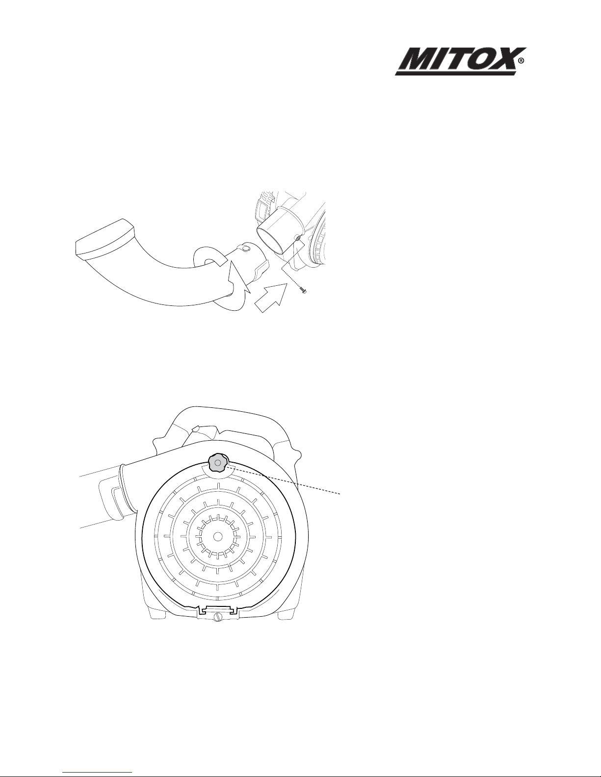
Assembling the Vacuum
1. Fit the Vacuum elbow tube over the
blower discharge port, aligning the
channels in the tube over the locking pin.
2. Twist the Vacuum elbow tube to engage
the locking pin as illustrated.
3. Lock the tube in place using 1 x M5x10
screw.
1.
2.
3.
Open the side cover using the
thumbscrew.
Page 7

26B Blower / 28BV Blower Vacuum
7
Original Instructions Version October 13
Fit the upper vacuum tube over the
vacuum intake port, aligning the channels
in the tube over the locking pin.
Twist the upper vacuum tube to engage
the locking pin as illustrated.
Attach the lower vacuum tube to the
upper vacuum tube using the same
method.
Fit the collection bag over the Vacuum
elbow tube using the velcro fastener.
Page 8

26B Blower / 28BV Blower Vacuum
8
Original Instructions Version October 13
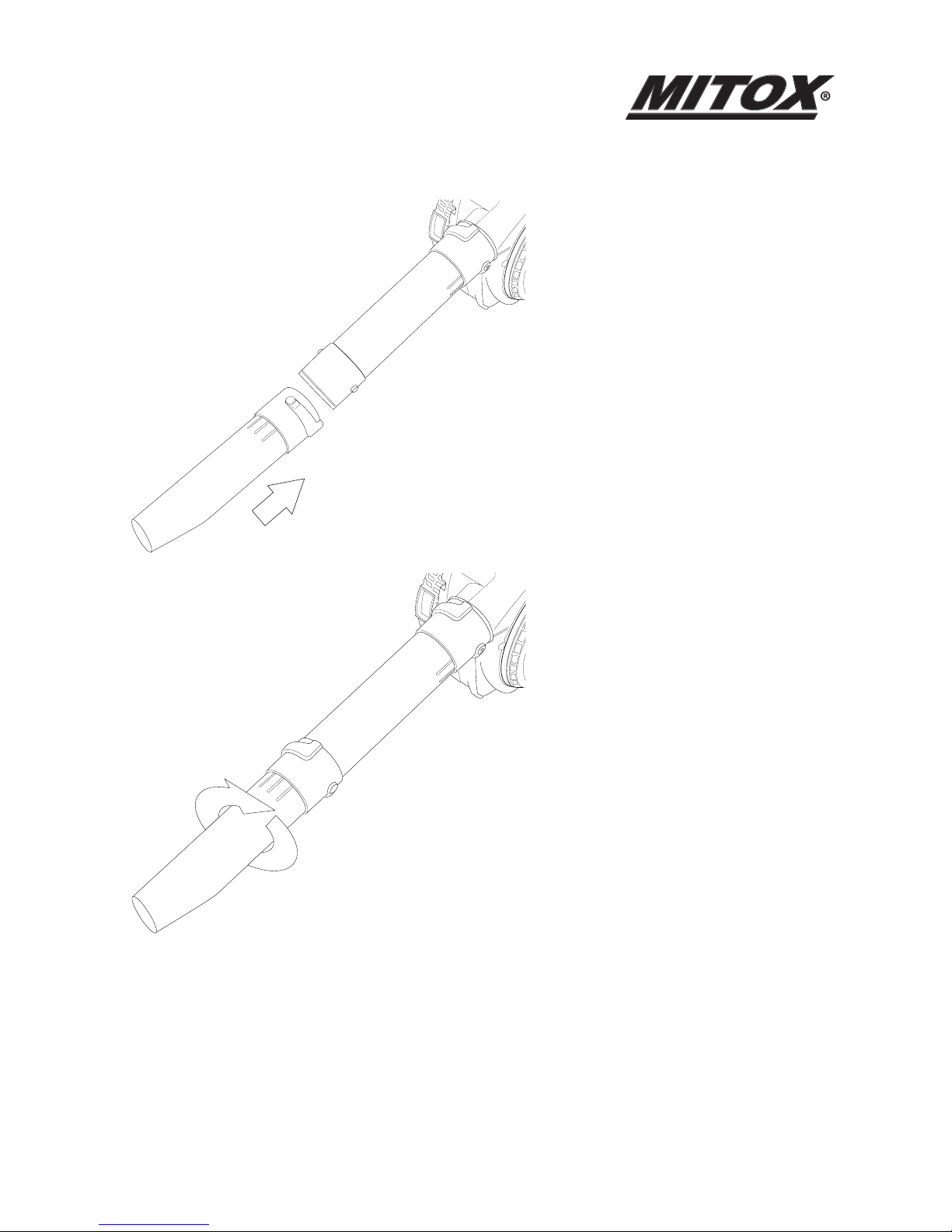
Assembling the Blower
Fit the straight blower tube over the
blower discharge port, aligning the
channels in the tube over the locking pin.
Twist the straight blower tube tube to
engage the locking pin as illustrated. Lock
the tube in place using 1 x M5x10 screw.
Page 9
26B Blower / 28BV Blower Vacuum
9
Original Instructions Version October 13
Important
Blower tube installation aects both blower Balance and performance! The tube and
Nozzle are correctly installed when the label “TOP” is visible to the operator during normal
operation.
Fit the tapered blower tube over the
straight blower tube, aligning the channels
in the tube over the locking pins.
Twist the tapered blower tube tube to
engage the locking pins as illustrated.
Note the tapered discharge chute is
marked with a TOP side.
Page 10

26B Blower / 28BV Blower Vacuum
10
Original Instructions Version October 13
Two-Stroke Fuel
Fuel is very ammable. Do not smoke or bring any ame or sparks near fuel.
Always stop the engine and allow it to cool before refuelling.
Refuel outdoors on bare ground, restart engine at least 5m away from the refuelling stop.
The engine is lubricated by oil mixed into petrol. Prepare a mixture of unleaded petrol and semi-synthetic
two-stroke oil that meets the specications of: API TC, ISO-L-EGC, JASO FC (Low Smoke) oil.
Recommended mixing ratio is 25:1.
FUEL WITH NO OIL (RAW PETROL) will cause severe damage to the engine which is not covered by
manufacturer’s warranty.
Use fresh, unleaded petrol (95 RON) and semi-synthetic oil specially made for high performance two-stroke
engines. Mix in a ratio of 25 parts petrol to 1 part of oil.
By using two-stroke oil specially made for two-stroke engines you will reduce the formation of ash and
carbon deposits on the spark plug, piston, exhaust muer and cylinder as well as reducing emissions of
harmful exhaust gases.
Oil FOR 4-CYCLE ENGINES should not be used as two-stroke lubrication oil as it can cause fouling of the spark
plug, exhaust port blocking, piston ring sticking and other internal engine damage.
Page 11

26B Blower / 28BV Blower Vacuum
11
Original Instructions Version October 13
Fuel Storage
Mixed two-stroke fuel which has been left unused for a period of one month or more may damage
the carburettor and result in the engine failing to start or operate correctly.
When storing the grass trimmer for a period of more than one month, empty the fuel tank, and
run the engine to empty the carburettor of fuel.
Two stroke fuel can cause deterioration of rubber and/or plastic components during prolonged
storage.
It is important to only use good quality, fresh fuel mix.
Page 12

26B Blower / 28BV Blower Vacuum
12
Original Instructions Version October 13
Fuelling
Shake the fuel container to thoroughly mix the two-
stroke oil and petrol.
Clean dirt from around the fuel cap before
removing.
Pour two-stroke fuel into the fuel tank with a
ltered funnel, up to 80% of the fuel tanks capacity.
Replace the fuel cap and tighten securely. Spilled
fuel must be wiped away from the blower before
starting the engine.
Move at least 5m away from the refuelling area before restarting the engine.
When relling the tank, always turn o the engine and allow it to cool down. Take a careful look around
to make sure that there are no sparks or open ames anywhere nearby before refuelling.
Page 13

26B Blower / 28BV Blower Vacuum
13
Original Instructions Version October 13
Starting the Machine
Page 14

26B Blower / 28BV Blower Vacuum
14
Original Instructions Version October 13
IMPORTANT !
A two-position “ON-OFF” switch located on the left of the machine handle grip controls the engine ignition.
Cold Engine Starting Procedure
1. 2.
3. Set the ignition switch to the ON position.
4. Slowly pull the recoil starter handle until engagement of the pawls with the ywheel is felt.
5. While holding the unit, pull out the starter rope rmly until engine res (indicated by a ‘cough’
from the engine).
6. Push the choke rod back in (choke is open).
7. Pull the starter rope until the engine starts.
8. Allow the engine to warm up before use.
Prime the fuel system by repeatedly
depressing the fuel primer bulb
until no air bubbles are visible in
the fuel discharge line.
Cold Engine Only. Choke the
engine by pulling the choke
control to the fully extended
position (choke is closed).
Page 15

26B Blower / 28BV Blower Vacuum
15
Original Instructions Version October 13
Hot Engine Starting Procedure
Set the ignition switch to the ON position .
Pull the starter rope until the engine starts.
If the engine does not start after 5 pulls, use the cold start procedure.
Overchoking
Should the engine become ooded due to overchoking, turn the ignition switch o, unscrew the spark plug,
wipe it dry or replace.
Stopping the Engine
Set the engine to idling by releasing the throttle lever.
Set the ignition switch to the o position OFF.
If the engine fails to stop, set the choke lever to the closed position to stall the engine; do not use the
machine until the ignition switch is repaired.
Page 16

26B Blower / 28BV Blower Vacuum
16
Original Instructions Version October 13
Adjusting the Engine Idle Speed
1. Start the engine by following the
procedures described on the preceding
pages.
2. Run the engine at idle speed until
operating temperature is reached (2-3
minutes).
3. Use a screwdriver to adjust the engine
idle speed to 2300-2500r/min.
Turn the idle screw clockwise to increase engine
idle speed.
Turn the idle screw counterclockwise to decrease
engine idle speed.
IMPORTANT !
Machine tubes and intake cover must be installed while adjusting engine idle! Engine idle speed will also be
aected if either the intake cover or machine tubes are blocked, damaged or incorrectly installed!
IMPORTANT !
If the engine continues to run with the ignition switch in the “OFF” position, stop the engine by pulling the
choke control out to the fully closed position.
A clean and unrestricted airow is essential to your machine’s engine performance and durability! Before
attempting any carburetor adjustments, inspect and clean the engine air cleaner as described on page 11 of
this manual.
Page 17

26B Blower / 28BV Blower Vacuum
17
Original Instructions Version October 13
Using the Machine
As a general rule, try to operate your machine at the lowest throttle setting necessary to get the job done:
• Use low throttle settings when clearing lightweight materials from around lawns or shrubbery.
• Use medium to higher throttle settings to move lightweight grass or leaves from parking lots or walkways.
• Use full throttle when moving heavy loads such as dirt or snow.
Safe operation
(1) Machine noise increases at higher throttle settings. Always use the lowest throttle setting required to get
the job done.
(2) Never operate the blower when visibility is poor.
(3) Always wear eye protection such as face shield or goggles while operating this machine.
(4) Wear a dust mask to reduce the risk of inhalation injuries.
(5) Wear close-tting clothing to protect your legs and arms.
(6) Wear hearing protection when operating this machine.
(7) Never operate the blower if any component parts are damaged, loose, or missing.
Page 18

26B Blower / 28BV Blower Vacuum
18
Original Instructions Version October 13
Using the Vacuum
Always be aware of the strength and direction of
stream. Never direct the blower discharge stream
toward people or animals.
Using the Blower
Always be aware of the strength and direction of
stream. Never direct the blower discharge stream
toward people or animals.
Page 19

26B Blower / 28BV Blower Vacuum
19
Original Instructions Version October 13
Routine Maintenance
Daily Maintenance
Remove dirt and debris from the blower exterior.
Inspect the engine, tank, and hoses for possible fuel leaks, and repair as necessary.
Inspect the engine cooling ns for accumulations of dirt or debris, and clean
as necessary.
Inspect the entire machine for damage, loose or missing components or fastenings, and repair as necessary.
Every 10 Hours Use (MORE FREQUENTLY IN DUSTY CONDITIONS)
1. Loosen the air cleaner cover retaining screw, and
remove the cover and lter element.
2. Inspect the element. If the element is distorted or
damaged, replace it with a new one.
3. Wash the element in clean fuel, and squeeze or
blow dry. Wash the air cleaner cover in clean fuel,
and wipe or blow dry.
4. Install the element and cover, and then tighten
the cover retaining screw.
Page 20

26B Blower / 28BV Blower Vacuum
20
Original Instructions Version October 13
Every 10/15 Hours Use
1. Use the spark plug wrench to remove the spark
plug (turn counter-clockwise to remove).
2. Clean and adjust the spark plug gap to
0.6~0.7mm. Replace any damaged or visibly worn
plug with a NGK BPMR7A or equivalent.
3. Install the spark plug nger-tight in the cylinder
head, and then tighten it rmly with the spark plug
wrench. If a torque wrench is available, torque the
spark plug to 148-165 inch pounds.
Every 50 Hours Use (MORE FREQUENTLY IF YOU NOTE REDUCED PERFORMANCE)
INSPECTION Inspect the entire machine and
tubes for damage, including loose or missing
components, and repair as necessary.
SPARK PLUG Replace the spark plug with a
NGK BPMR7A , gapped to( 0.6~0.7)mm.
FUEL FILTER Use a wire hook to extract the fuel lter
from inside the fuel tank, and then remove and
wash the lter element in clean fuel.
Before reinstalling the lter, inspect the condition
of the fuel line. If damage or deterioration is noted,
the vacuum should be removed from service until
it can be inspected by a trained service technician.
COOLING SYSTEM Remove the engine cover (as described under “Spark Arrestor”), and use a wood or plastic
scraper and a soft brush to remove dirt and debris from the cylinder ns and crankcase.
Page 21

26B Blower / 28BV Blower Vacuum
21
Original Instructions Version October 13
Spark Arrestor Maintenance
Hard starting or gradual loss of performance can be caused by carbon deposits lodged in the spark arrestor
screen. For maximum performance, the spark arrestor screen should be periodically cleaned as follows:
1. Remove the spark plug.
2. Remove three self- tapping screws and two machine screws from the engine cover, and then
gently move the engine cover aside.
3. Remove the three-spark arrestor retaining screws, and then remove the spark arrestor cover,
screen, gasket, and chamber.
4. Use a plastic scraper or wire brush to remove carbon deposits from the arrestor screen, chamber,
and cover.
5. Inspect the screen carefully, and replace any screen that has been perforated, distorted, or is
otherwise unserviceable.
6. Install the chamber, screen, gasket and cover in the reverse order of disassembly, and then install
and securely tighten the three cover retaining screws.
7. Install the engine cover, and verify that the fuel line connections are still tightly in place.
8. Install the engine cover retaining screws in the reverse order of removal, and tighten securely.
9. Install and tighten the spark plug, and reconnect the spark plug wire.
Page 22

26B Blower / 28BV Blower Vacuum
22
Original Instructions Version October 13
Storage (30 days or longer)
CLEANING Thoroughly clean the machine exterior.
INSPECTION Inspect the entire machine and tubes
for damage, including loose or missing components,
and repair as necessary.
FUEL Drain the fuel tank, and then clear the carburetor and lines by running the
machine until it stops from lack of fuel.
LUBRICATION Remove the spark plug, and then pour approximately 1/4-oz of oil into the cylinder through
the spark plug hole. Before reinstalling the spark plug, pull the recoil starter 2 or 3 times to distribute the oil
over the cylinder walls.
AIR CLEANER Remove, clean, and reinstall the lter element as described under “daily maintenance.”
STORAGE Store the machine in a clean, dry, dust-free environment.
IMPORTANT!
• After every use, check that all nuts, bolts and screws are securely fastened and tighten if
necessary.
• In the event of an accident, breakdown or blockage, ensure the engine is turned o
before any work is carried out to rectify this.
• Make sure the engine has stopped and is cool before performing any service to the
machine. Contact with moving parts or hot muer may result in a personal injury.
Always wear heavy-duty gloves when handling the blades.
Transportation
• Never transport the Blow/Vac with the engine running. An engine that is running could be
accidently accelerated causing the implleor to engage.
• Make sure the blade safety guards are in place when transporting the Blow/Vac.
• Ensure the Blow/Vac is secure when transporting in a vehicle and the tank is drained of fuel.
Page 23

26B Blower / 28BV Blower Vacuum
23
Original Instructions Version October 13
Page 24

26B Blower / 28BV Blower Vacuum
24
Original Instructions Version October 13
Page 25

26B Blower / 28BV Blower Vacuum
25
Original Instructions Version October 13
Page 26

26B Blower / 28BV Blower Vacuum
26
Original Instructions Version October 13
Page 27

26B Blower / 28BV Blower Vacuum
27
Original Instructions Version October 13
Page 28

26B Blower / 28BV Blower Vacuum
28
Original Instructions Version October 13
Page 29

26B Blower / 28BV Blower Vacuum
29
Original Instructions Version October 13
Page 30

26B Blower / 28BV Blower Vacuum
30
Original Instructions Version October 13
Page 31

26B Blower / 28BV Blower Vacuum
31
Original Instructions Version October 13
Page 32

26B Blower / 28BV Blower Vacuum
32
Original Instructions Version October 13
CONDITIONS OF WARRANTY
The manufacturer warrants the product against faulty materials and workmanship for a period of 2 years from
the date of rst purchase. The warranty is applicable when the product is used in a “home owner” application.
If products are used for commercial or professional purposes, the warranty period is for 3 months from the
date of rst purchase. Warranty does not extend to failure due to fair wear and tear.
The manufacturer undertakes to replace, any spare parts that are classied as defective by an appointed
Mitox service dealer. The manufacturer will not accept liability for the replacement of the machine, either
partially or wholly, and /or consequential damages and /or interest charges either directly or indirectly.
Warranty does not cover failure due to:
Insucient maintenance.
Incorrect fuel mixture and stale fuel.
Abnormal use or accidental damage.
Incorrect assembly, adjustment or operation of the product.
Spare parts that are subject to wear e.g. safety parts, blades, blade supports, bearings, cables, guards,
deectors, spark plugs, air lters etc.
Neither does warranty extend to:
Freight and packing costs.
Use of non-genuine spare parts i.e. those from another manufacturer.
Use of the machine for any other purpose than that for which it was designed.
Use and maintenance of the machine in a manner not described in the owner’s manual.
As part of our policy of continuous product improvement, we reserve the right to alter or amend this
specication without notice. As a result, the product may dier from the information contained herein but
any alteration will only be implemented without notice if it is classied as an improvement to the above
specication.
READ THE MANUAL CAREFULLY BEFORE OPERATING THE MACHINE
When ordering spare parts, please quote the part number, this can be found in the parts list included in this
manual.
Retain the receipt of purchase without which no warranty can be oered.
Distributed by Mitox Garden Machinery
Wincanton Business Park
Wincanton
Somerset
BA9 9RS
 Loading...