

Page 1
EMF MeterManual (A6) V1.indd 1
Protecting your health
in a wireless world.
EMF METER
USER MANUAL
2/14/18 1:41 PM
Page 2
Introduction
The Mito Meter is a compact, simple to use, but
sophisticated, general purpose EMF (Electromagnetic
Field) meter that can measure EMF intensity from: cell
towers, mobile phones, smart meters, Wi-Fi routers,
various cordless devices, magnetic and electric elds
from power lines, fuse boxes, home appliances and
more.
The Mito Meter can also detect spy cameras, wireless
bugs, and other such devices across a very wide
frequency range (see details below).
It was designed, with great care, to assist EMF sensitive
people; allowing them to monitor their environment
during daily activities with a simple device that may be
carried in a pocket or purse. (Weighing less than 2
ounces, or 50 grams). The Mito Meter may also be
connected to a computer, making it an invaluable tool
in research and tech environments.
EMF MeterManual (A6) V1.indd 2 2/14/18 1:41 PM
Page 3
IMPORTANT NOTICE
This detector shows the intensity of measurements using 9
LEDs: Green,Yellow and Red.
(Green = low, Red = high)
These colors are intended as a visual guide , and not to
indicate safe or unsafe readings. Furthermore, this device is
intended to allow non-professionals to measure EMF levels
with a simple, intuitive interface. Measurements taken for
legal or professional use require special equipment, and
trained operators.
EMF MeterManual (A6) V1.indd 3 2/14/18 1:41 PM
Page 4
EMF MeterManual (A6) V1.indd 4
Package Contents
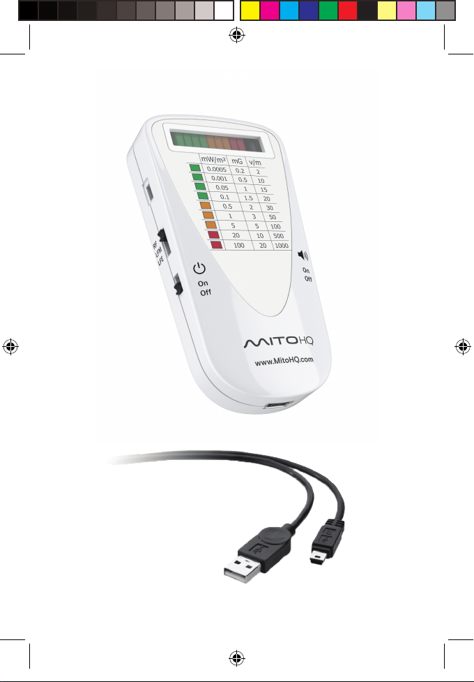
Mito Meter including: 1x LiPo rechargeable battery
•
(installed).
• Mini-USB (1 Meter) cable for charging and data
transfer. Note: This is a non-standard cable
designed especially for use with this product.
• USB Adaptor (Female) to USB C (Male).
Note: Proprietary software, for use with this product,
is available at:
https://mitohq.com/mito-meter-resources/
Drivers available at:
https://mitohq.com/mito-meter-resources/
2/14/18 1:41 PM
Page 5
EMF MeterManual (A6) V1.indd 5 2/14/18 1:41 PM
Page 6
Operation
The Mito Meter is a 3-mode detector, these modes are:
• RF - Radio Frequency
• LFM - Low Frequency Magnetic
• LFE - Low Frequency Electric
It is recommended to fully charge the device before using it
for the rst time. To do so, use the supplied mini-USB cable
to connect to a USB charger or computer. During charging,
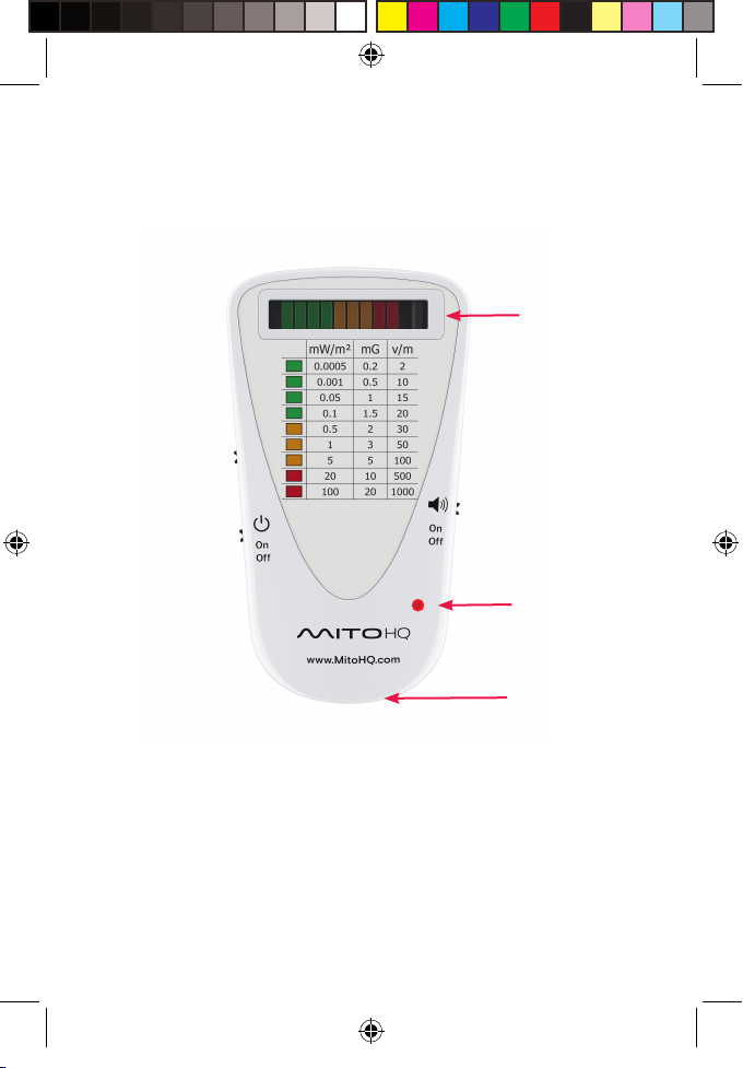
the LED will show RED – when fully charged the LED will be
o. A full charge should give 8-10 hours of operation.
Note: On activation the meter will perform a quick (3
second) self-test before full operation. This includes:
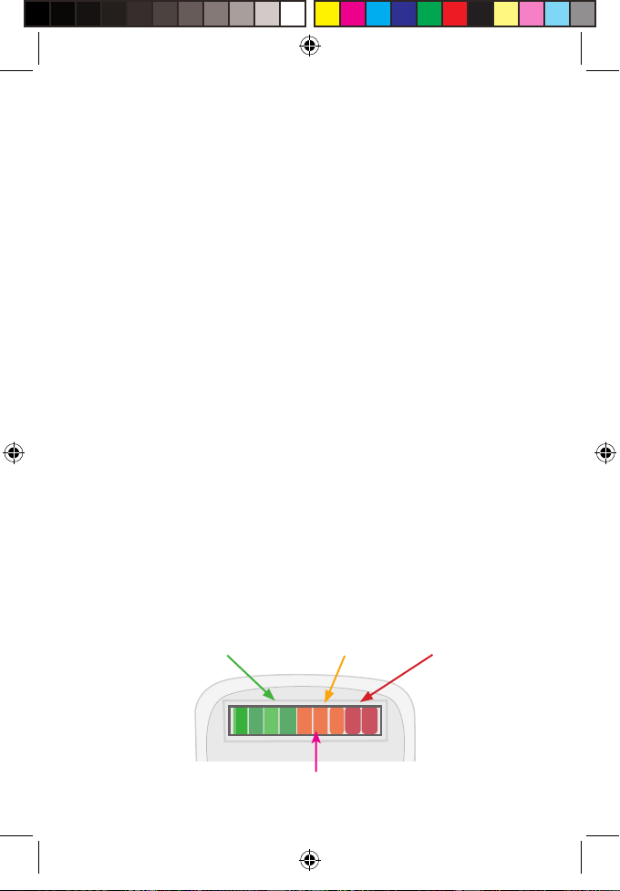
• Cycling through the LEDs from left to right, accompanied
by a tone. (If the sound is turned ON).
• The device will then check the battery status and show
the charge:
100% 90% 80% 70% 60% 50% 40% 30% 20%
Battery level indicators
(During self-test)
EMF MeterManual (A6) V1.indd 6 2/14/18 1:41 PM
Page 7
EMF MeterManual (A6) V1.indd 7
EMF Levels
Charging
(Hidden when
not active)
USB Connection
2/14/18 1:41 PM
Page 8
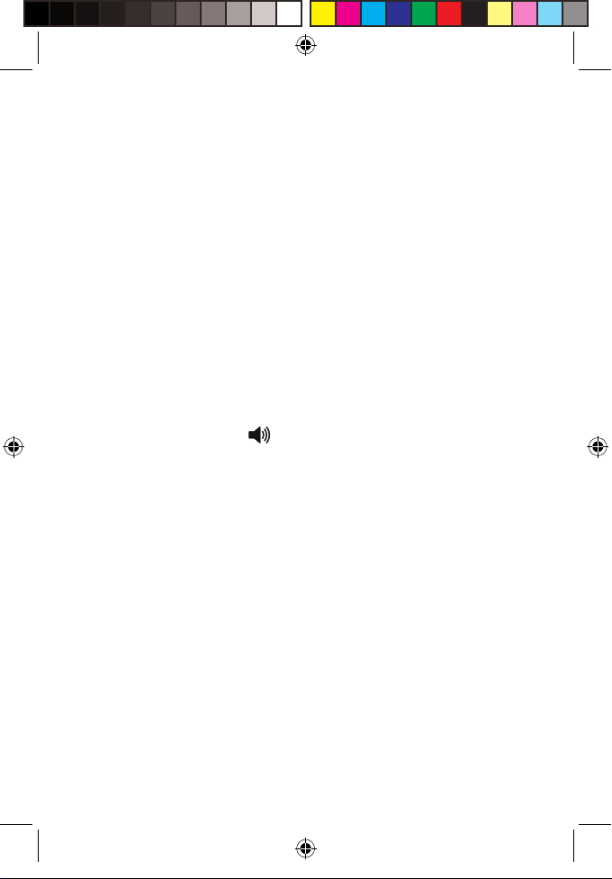
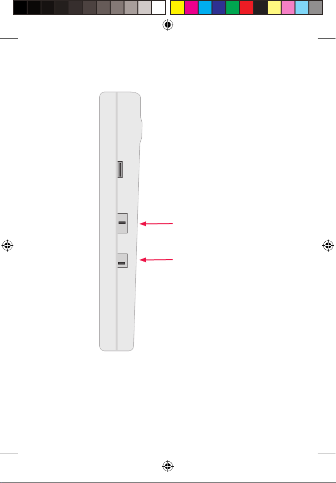
Turn the meter on with the Power ON/OFF switch.
Use the Mode Switch to select a detection mode:
• RF Mode – the detectors measures radio frequencies in
the dened range. (See specications.)
• LF-M Mode – the detector measures low frequency
magnetic elds
• LF-E Mode – the detector measures low
frequency electric elds.
Readings in the Yellow or Red zone, will be accompanied
by a tone; this feature may be disabled by using the sound
on/o switch.
This detector is a peak level detector, which means that on
every update it shows the maximum, or peak level,
detected since the last update. Updates are recorded
approximately 5 times a second for the LEDs, and twice a
second by the PC software.
Note: The Mito Meter is a broadband detector, meaning it
captures all signals from all sources within the selected
mode frequency range at a particular location. For
example: in RF mode, if both a Wi-Fi router and cell phone
transmit at the same time, the meter will capture both
signals and give a combined result.
EMF MeterManual (A6) V1.indd 8 2/14/18 1:41 PM
Page 9
RF
EMF MeterManual (A6) V1.indd 9
LFM
LFE
Mode Switch
Power ON/OFF
2/14/18 1:41 PM
Page 10
EMF MeterManual (A6) V1.indd 10
Performing Measurements
Switch on the device and select a measurement mode:
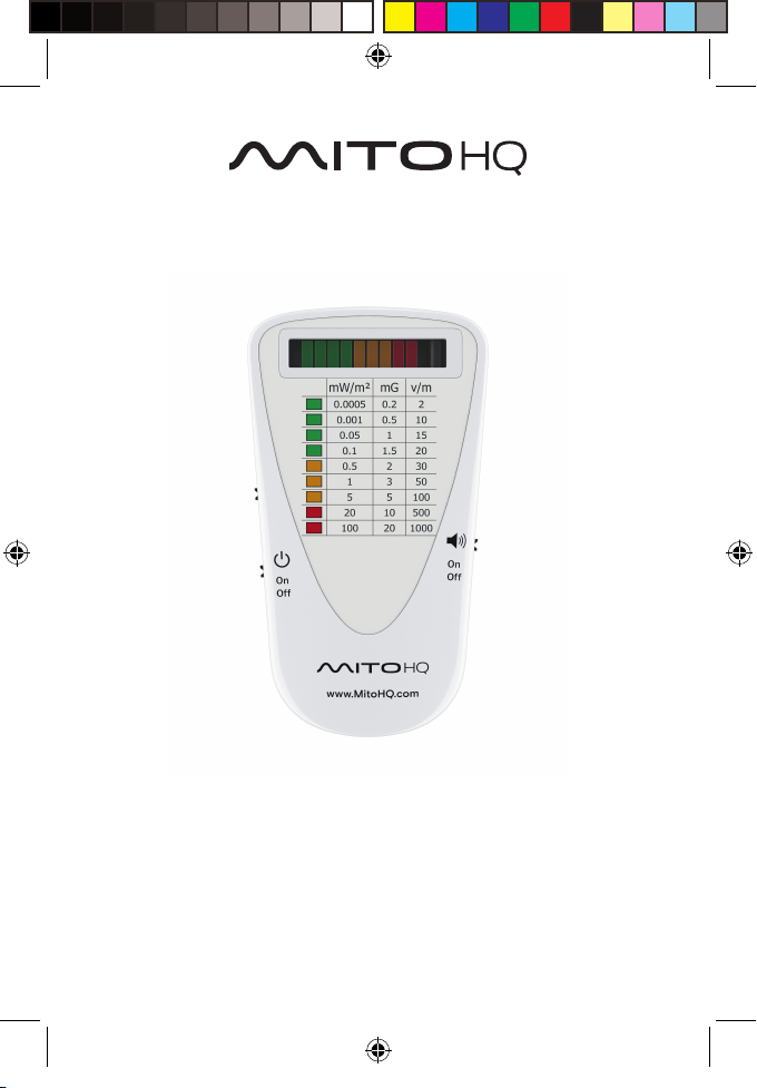
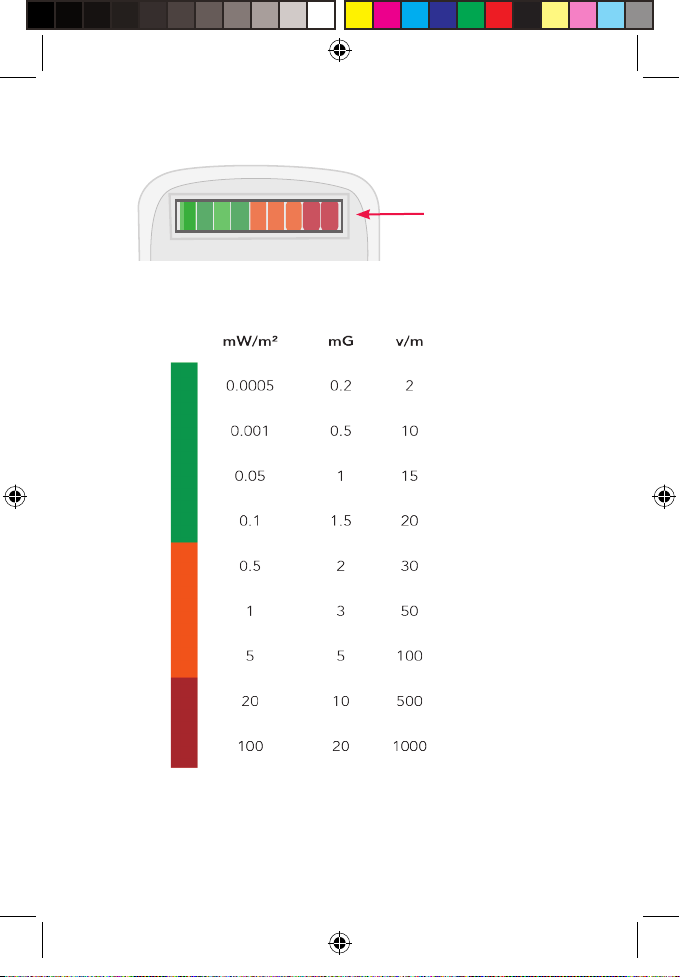
There are 9 levels of intensity shown by 9 LEDs: from GREEN
through YELLOW to RED. By matching the LED reading with
the appropriate numbers on the chart, numerical values
can be noted.
The device uses directional antennas for the
measurements, thus it is necessary to carefully rotate the
device in all directions at any location a measurement is
performed. The readings may change as the device is
rotated – the highest reading found is the correct one.
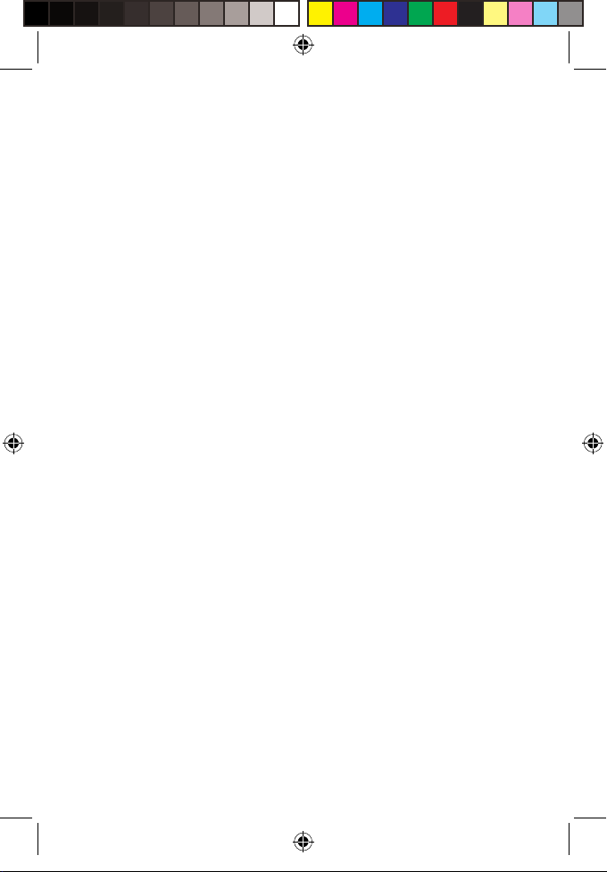
The RF and LFE antennas are located on the left side of the
device – blocking them with your grip may reduce the
reading. When performing RF and LFE measurements, the
device should be held using the right hand on the right
side of the Meter.
2/14/18 1:41 PM
Page 11
EMF MeterManual (A6) V1.indd 11
EMF Levels
2/14/18 1:41 PM
Page 12
Understanding the Readings
mW/m² = Milliwatts per square meter
Used to measure the power density of an RF (Radio
Frequency) source. Use this value when measuring EMF
from: cell towers, smart meters, Wi-Fi, Bluetooth, cordless
phones and microwave ovens.
mG = Milligauss
Used to measure AC (Alternating Current) magnetic eld
intensity, such as from AC power lines, fuse boxes, and
home appliances.
Note: This meter cannot detect DC (Direct Current)
magnetic elds, such as those from magnets.
V/m = Volts per meter
This is used to measure the intensity of an electric eld
near voltage sources such as power outlets and power
lines.
EMF MeterManual (A6) V1.indd 12 2/14/18 1:41 PM
Page 13
EMF MeterManual (A6) V1.indd 13
Notes on Signal Sources
•
Be aware that some EMF sources in the home, such as
cell phones, smart meters, and Wi-Fi emitters (RF
signals), change levels very rapidly due to protocol
denitions.
• Cell phones will adjust their levels based on the signal
strength from the cell tower and any intervening
obstacles to that signal.
• Smart-meters often send very fast signal bursts every few
seconds. And Wi-Fi routers adjust signal strength based
on the transfer load.
• LFM and LFE sources are usually more consistent, but, as
with RF signals, the device must be rotated to all
directions to nd the highest, and most accurate,
reading.
• Also, Users should be aware that measuring too close to
a transmitter will reduce the accuracy of the
measurement considerably. (Further reading on the
topic of near and far elds is advisable, and not covered
here.)
2/14/18 1:41 PM
Page 14
EMF MeterManual (A6) V1.indd 14
Using and Installing the Software
The Mito Meter software (which is a download) can be used
to record and view readings from the Meter once it is
connected to a PC using the supplied mini-USB cable.
Files are saved in CSV format, and can be imported into
Microsoft Excel or other similar software.
Before connecting the device to your PC and using the
software, it will be necessary to download and install the
correct drivers for this device.
Download these drivers at:
https://mitohq.com/mito-meter-resources/
Download the latest version of the Mito Meter software
here:
https://mitohq.com/mito-meter-resources/
2/14/18 1:41 PM
Page 15
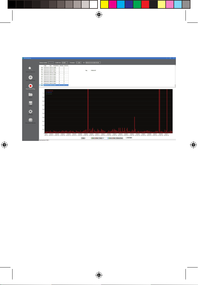
The software downloads as a zip le – Unzip the le
and run the “Monitoring.exe” le. No installation is
required.
Supported OS: Windows 7, Windows 8, Windows 8.1
and Windows 10.
EMF MeterManual (A6) V1.indd 15 2/14/18 1:41 PM
Page 16
Driver Installation
Download the drivers from:
https://mitohq.com/mito-meter-resources/
Open the download and start the installation by following
the on-screen instructions. (See graphic)
Once installed, no further action is required.
EMF MeterManual (A6) V1.indd 16 2/14/18 1:41 PM
Page 17
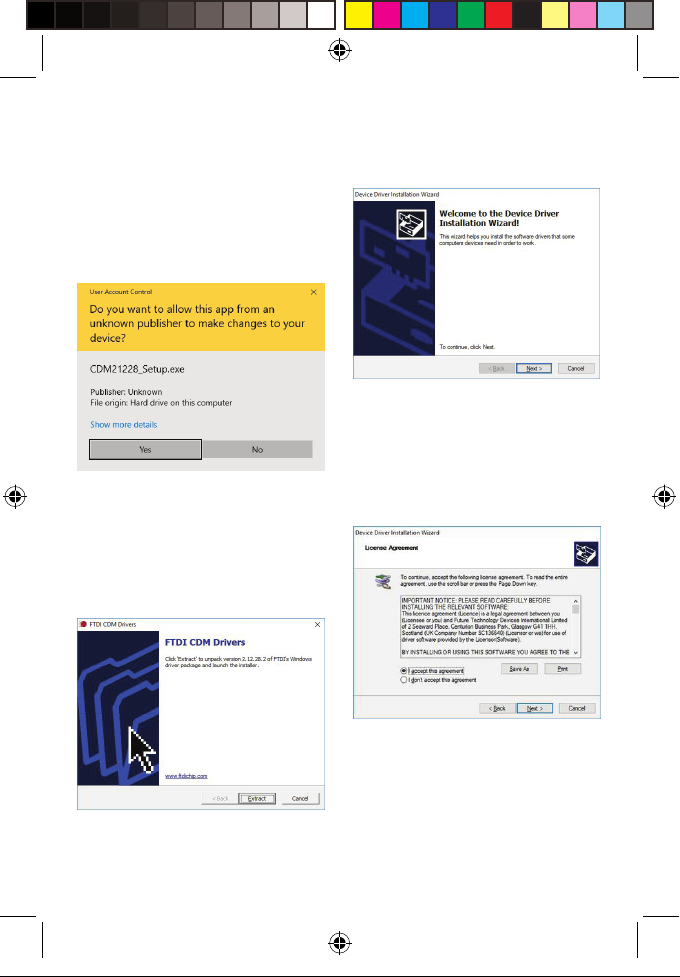
DOWNLOAD AND OPEN
EMF MeterManual (A6) V1.indd 17
FILE:
1.
Accept by clicking ‘Yes’.
2.
3.
Follow instructions to install
the Driver.
4.
Accept and install.
Firmware Installation
2/14/18 1:41 PM
Page 18
Using the Software
Connect the meter to a PC using the special mini-USB cable
supplied, and power ON.
• On your PC: Open the Mito Meter application. Make sure
the Meter is turned on, and that it is connected to the PC
via the supplied USB cable. Now ‘click’ the “Search device”
button. The software will locate the device, and, once
found, will show the device, along with the model name
and rmware version at the top of the application
window. Once connected, it is possible to start capturing
data.
• Press the “Start Recording” button to capture real-time
data from the device. The device updates readings twice
a second, using the peak value for that time segment.
• To stop the capture, press the “Stop Recording” button.
• Data may be saved to a le by pressing the “Sa ve” button;
choose a location on your hard drive and press Save.
• Recorded data may be viewed by either: Pressing the
“Open” button and navigating to a saved le, or by
left-clicking in the graph area on the screen.
EMF MeterManual (A6) V1.indd 18 2/14/18 1:41 PM
Page 19
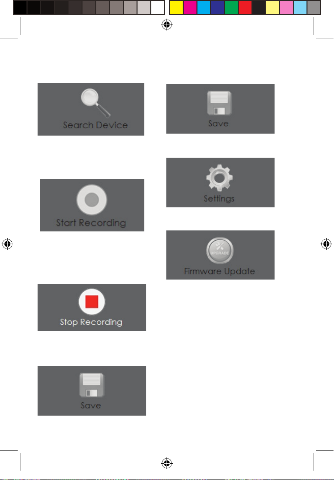
compatible device via the COM
port on your computer.
Starts data collection from the
device.
(This button will only work if a
compatible device is connected.)
Stops data collection from the
device.
Save collected data to le.
Save collected data to le.Search for and connect to a
Enter software settings.
Updates the rmware on the
device.
Application Window
Features and Controls
EMF MeterManual (A6) V1.indd 19 2/14/18 1:41 PM
Page 20
Firmware Updates
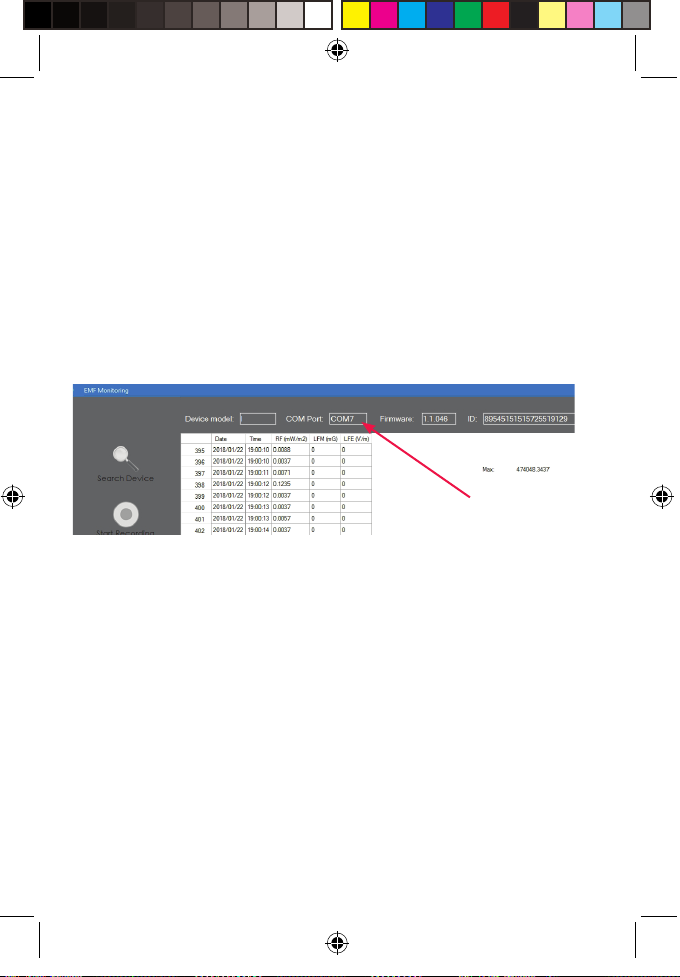
Firmware, is software installed on the Meter. It is
important to check that the version on the Meter is up to
date.
The current rmware on the device will be shown at the
top of the application window once the device is
connected:
Firmware Version
Go to our website to check for the latest release at:
https://mitohq.com/mito-meter-resources/
If there is a later version available download it to your
computer.
Once you have the le on your local drive: Click the
“Firmware Update” button – you will be prompted to
locate the le you have downloaded.
2/14/18 1:41 PM
Page 21
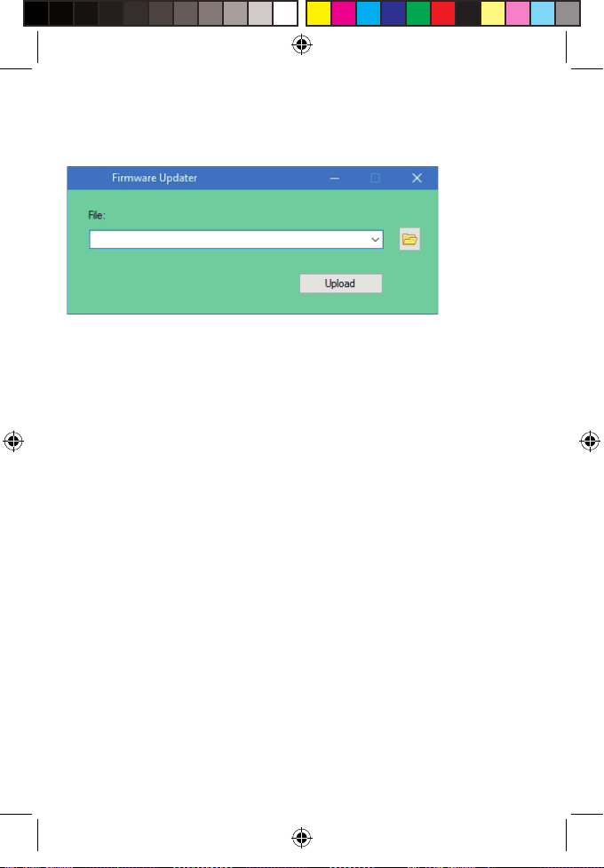
Enter the location, on your hard drive, of the le
that you have downloaded, and click “Upload.” The
rmware on your device will be updated.
Note: The Meter must be connected to the computer via
the USB cable.
EMF MeterManual (A6) V1.indd 21 2/14/18 1:41 PM
Page 22
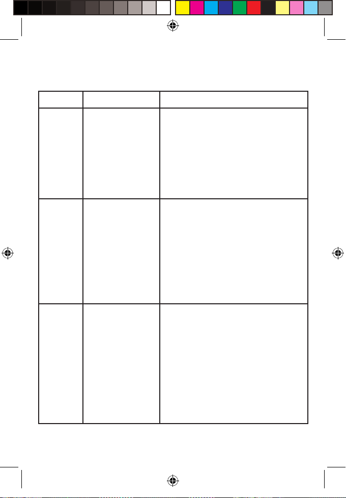
Troubleshooting
Question: Answer:
Mito
Meter
The device
does not turn
on when not
connected to
the USB.
•
The battery is not charged.
Connect the device to a
power source with the USB
cable, and allow to charge
for several hours.
Mito
Meter
Software
EMF MeterManual (A6) V1.indd 22 2/14/18 1:41 PM
No tones from
meter
The software
cannot nd the
device.
•
Make sure the sound switch
is in the ON position.
Note: Tones only sound for
•
measurements high
enough to activate the
Yellow or Red LEDs.
•
Make sure the device is
turned on.
•
Make sure to use the
correct USB cable.
(The cable supplied is of
special design – regular
mini-USB cables will not
function correctly).
Page 23
EMF MeterManual (A6) V1.indd 23
Maintenance
Always keep the device away from excessive heat or
humidity.
Note: Please remember to follow local ordinances
regarding disposal of electronic equipment.
Warranty
The Mito Meter comes with a 1 year limited warranty.
For more information, or to contact us, please email
to: [email protected]
2/14/18 1:41 PM
Page 24
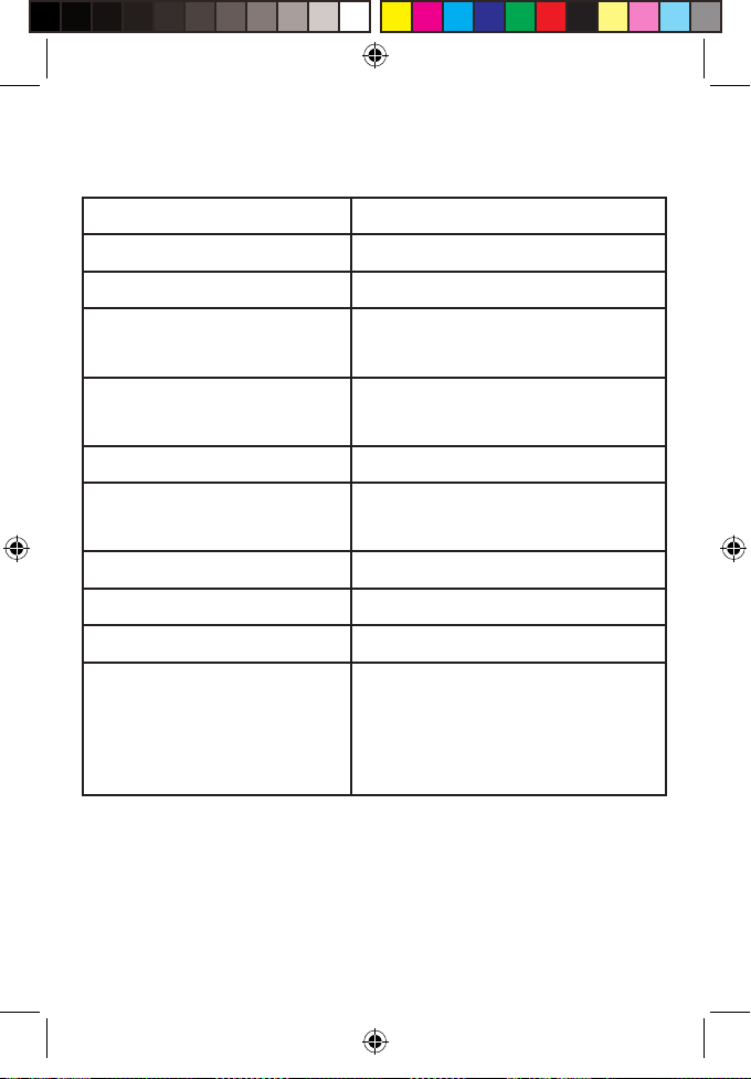
Technical Specications
RF Frequency range: 100MHz to 8GHz
RF measuring range: -60dBm to +5dBm
RF Typical accuracy: ±6 dB
LFM (magnetic eld)
Frequency range:
LFM measuring range: 0mG to 50mG with 0.1mG
LFM accuracy: 20%
LFE (electric eld)
Frequency range:
LFE measuring range: 2v/m to 1000v/m
LFE accuracy: 25%
Display: Sampling rate:
50Hz to 10KHz
resolution
50Hz-50KHz
EMF MeterManual (A6) V1.indd 24 2/14/18 1:41 PM
Sampling rate:
20,000/sec (updates 5 times
a second on the LEDs / 2
times a second for USB
data)
Page 25
EMF MeterManual (A6) V1.indd 25 2/14/18 1:41 PM
 Loading...