

ver. 1.0 PRINTED IN KOREA
20-CS-110
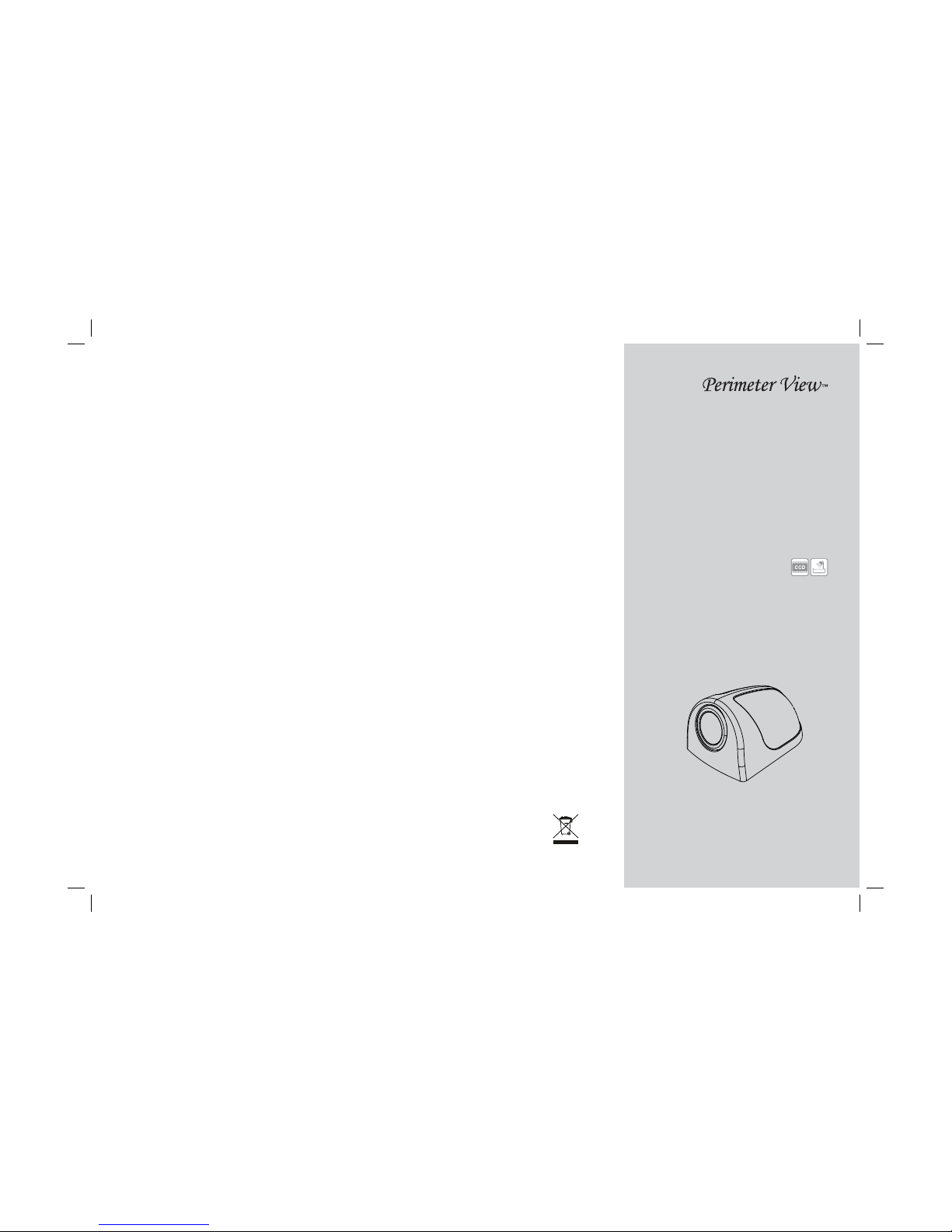
SIDE-VIEW FOR VEHICLE
Thank you for purchasing this product.
For proper usages and application,
Please read this instruction manual thoroughly.
INSTRUCTION MANUAL
※ Design and speci cations could be changed without notices.

3
CONTENTS
Safety Rules
1. Features
2. Box Contents
3. Installation
4. Connection
5. Cleaning & General maintenance
6. Speci cations
..................................................................................... 4
........................................................................................ 5
.............................................................................. 5
.................................................................................. 6
................................................................................. 8
...................................... 9
............................................................................. 9

4 5
(LENS)
■ 1/4” IT COLOR CCD image sensor
■ Zn die-casting body
■ Compact size
■ Waterproof (IP-67)
(HOUSING)
■ PC-BODY application
■ Simple assemblling with hook.
1 FEATURES
2 BOX CONTENTS
Camera Bracket Set
Camera
Instruction
Manual
Bottom Rubber
Extension Cable
15ft (4.6m)
Screws set
WARNING
Please read the “Safety Rules” carefully before using this product. Following the
safety rules prevents users from damages related with the misuse of the product.
It is very important to follow these safety rules. We state “Caution” and “Warning”
to clarify any potential risk for a damage associated with the misuse of the product.
SAFTY RULES
May cause bodily harm or even
death if the user ignores these
warnings in the safety rules.
Warning
May cause a damage or shorten
the life time of the product if the
user ignores these cautions in
the safety rules.
Caution
CAUTION
When the power cable cord touches a metal case, cover it with a insulation tape.
--- Short circuit or disconnection of wire may cause a re or accident.
Do not use bolts or nuts from a parts for vehicle.
--- Using bolt or nuts from steering column or break may cause an accident.
Let professional engineers or the sale store install the camera.
--- It require the experience and skills from professional engineers for proper
installation and wiring.
After installing the camera, check it break lamp, head lamp and wipe works
properly.
Install this camera to the vehicle with DC 12V.
Do not dissassemble the device.
--- It may cause a re or malfunction of device.
Do not install the camera projected out from the vehicle.
--- It may harm the pedestriants.
Do not let the extension cable pass through the seat rail. properly wire the
cables.
--- It may cause a re or and accident.
Do not install the camera bracket on the surface of glass.
--- Use the screws to install the camera bracket.

6 7
When install CS-110 camera, place “TOP” face to upside.
3 INSTALLATION
TOP
RL
1:1 size
(1) Verify the position of ‘TOP’
which should be upper side
and x it to the lens bracket
with screws.
(2) Then install it to the bottom
bracket.
(3) Select and clean the position for the camera
installation.
(4) Fix the pre-installed camera
using the rubber packing and
screws.
(5) Then cover it with the camera housing like the
picture.
※ Based on the condition and place, the installation procedures
could be varied.
⑤
⑥
⑦
⑧
MACHINE SCREW M3.0 X 4 (1ea)
TAPPING SCREW T2 M3.0 X 6 (2ea)
TAPPING SCREW T1 M3.0 X 12 (2ea)

8 9
5 CLEANING & GENERAL MAINTENANCE
6 SPECIFICATION
※ If your vehicle has been parked in direct sun light resulting in a considerable
rise in temperature inside the vehicle, allow the unit to cool o before
operating.
CLEANING
Unplug or power o mode before cleaning. Do not use liquid cleaners or
aerosol ceaners. Use a damp cloth for cleaning.
OBJECT AND LIQUID ENTRY
Never push objects of any kind into this monitor equipment through
holes as they may touch dangerous voltage points or short-out parts that
could result in a re of electric shock. Never spill liquid of any kind on the
product.
SERVICING
Do not attempt to service this system by yourself as opening or removing
covers may eapose you to dangerous voltage or other hazards. Refer all
servicing to quali ed service personnel.
Operating temperature
-4℉ to 122℉ / -20℃ to 50℃
0.18lb (79.5g)
Minimum illumination
1Lux
Image device (NTSC/PAL)
1/4” IT COLOR CCD Image Sensor
View of angle (H/V/D)
71/47/74 deg
Input Voltage
DC 5V~15V/100mA max @ 12V
Camera Weight
Demension
2.44(W) x 1.18(H) x 1.57(D) inch
62(W) x 30(H) x 40(D) mm
Bottom Rubber ---------------------------------------- 1
Accessories
Screws set ------------------------------------------------ 1
Extension Cable --------------------------------------- 1
4 CONNECTION
CS-110
CAMERA CONNECTOR
1. POWER IN (DC +12V)
2. N.C
3. N.C
4. VIDEO OUT
5. N.C
6. N.C
7. GND
Monitor
(Option)
Extension Cable
15ft (4.6m)
Side Camera
Before making the connection, disconnect the ground terminal of the car battery
to avoid short circuiting.
Before inserting plug, should check pin speci cation and the plug should insert
to jack or connector rmly.
If forced insert wrong direction, it may cause malfunction.
When connect extension cable, turn it right direction as described arrow.

MEMO MEMO
 Loading...