

Page 1
OPERATOR’S
MANUAL
PRESSURE
PRESSURE
WASHERS
WASHERS
Electrically
Heated
Mi-T-M® CORPORATION, 8650 Enterprise Drive, Peosta, IA 52068
Tel: (800) 553-9053 Fax: (563) 556-1235
e-mail: [email protected] Website: http://www.mitm.com
Page 2

TABLE OF CONTENTS
Important Safety Instructions . . . . . . . . . . . . . . . . . . . . . . . . . . . . . . . . . . . . . 3
Pre-Operating Instructions . . . . . . . . . . . . . . . . . . . . . . . . . . . . . . . . . . . . . . 4
Operating Instructions . . . . . . . . . . . . . . . . . . . . . . . . . . . . . . . . . . . . . . . . .5-6
Changing Pressure . . . . . . . . . . . . . . . . . . . . . . . . . . . . . . . . . . . . . . . . . . . . 6
Safety Components . . . . . . . . . . . . . . . . . . . . . . . . . . . . . . . . . . . . . . . . . . . . 7
Things to Check Regularly . . . . . . . . . . . . . . . . . . . . . . . . . . . . . . . . . . . . . . 8
Winterize Your Pressure Washer . . . . . . . . . . . . . . . . . . . . . . . . . . . . . . . . . 8
Service and Maintenance . . . . . . . . . . . . . . . . . . . . . . . . . . . . . . . . . . . . . . . 9
Specifications, Features and Options . . . . . . . . . . . . . . . . . . . . . . . . . . . . . 10
Electrical Control Panel . . . . . . . . . . . . . . . . . . . . . . . . . . . . . . . . . . . . . . . . 11
Electrically Heated Parts Breakdown . . . . . . . . . . . . . . . . . . . . . . . . . . .14-15
Pump Parts List
General Pump - Model TS1331 . . . . . . . . . . . . . . . . . . . . . . . . . . . . . . . 18
General Pump - Model TS2011 . . . . . . . . . . . . . . . . . . . . . . . . . . . . . . . 19
Unloader Valve . . . . . . . . . . . . . . . . . . . . . . . . . . . . . . . . . . . . . . . . . . . .16-17
Schematics . . . . . . . . . . . . . . . . . . . . . . . . . . . . . . . . . . . . . . . . . . . . . . .12-13
Trouble Shoot . . . . . . . . . . . . . . . . . . . . . . . . . . . . . . . . . . . . . . . . . . . . . . . 20
®
Mi-T-M
Warranty . . . . . . . . . . . . . . . . . . . . . . . . . . . . . . . . . . . . . . . . . . . . 21
2
Page 3

IMPORTANT SAFETY INSTRUCTIONS
1. Read all safety and operating instructions before using the unit.
2. Read all electrical hook up instructions.
3. Read warnings on additive containers.
4. Ventilate work area when using toxic or pungent additives to reduce your exposure to
toxic fumes.
5. Use protective wear, especially for the eyes and skin.
6. Be careful of slippery floors. Some additives make a normally safe area extremely
slippery and dangerous.
7. Keep children away from the machine and wash area.
8. Do not change nozzle size. Each machine is designed to operate with a specific size
nozzle. An incorrect nozzle could cause excessive pressure resulting in pump damage
and possible personal injury. Refer to parts list for correct nozzle size.
9. Do not point the nozzle where damage or injury cold result (eg. eyes, skin). The water
discharge from this unit is under extremely high pressure.
10. Do not point the nozzle toward an electrical outlet as you risk severe shock and personal
injury.
3
Page 4

PRE-OPERATING INSTRUCTIONS
When unpacking the unit, if you find damage due to shipping, contact your dealer or Mi-T-M
Corporation immediately,
ELECTRICAL SUPPLY
Arrange with an electrician to install a properly grounded, three phase service. To protect the
receptacle from splashes, the recommended height above the ground level is a minimum of
four feet. A ground fault interrupter (GFI) should be used. Make sure the supply voltage is
correct. The voltage is shown on the rating plate of the unit, or see “Specifications, Features
and Options” sheet in this manual.
IMPORTANT!
DO NOT CHANGE THE AC PLUG ON THE UNIT TO A DIFFERENT TYPE DO NOT CUT
OFF THE GROUND PIN OR THE OPERATOR WILL BE EXPOSED TO SEVERE SHOCK.
KEEP ELECTRICAL CORDS AND CONNECTIONS DRY AT ALL TIMES.
INCOMING WATER SUPPLY
Connect a garden hose to the water inlet of the unit. The water supply must be able to deliver
5-8 gallons per minute at a minimum pressure of 5 psi. See “Specifications, Features and
Options” sheet in this manual.
HIGH PRESSURE NOZZLE
Attach the high pressure nozzle (sent with operator's manual), to the trigger gun extension.
4
Page 5

When unpacking the unit, if you find damage due to shipping, contact your dealer or Mi-T-M Corporation
immediately,
HOT PRESSURE WASHER MODE (P Units only)
SET-UP PROCEDURE:
1. Connect water supply to inlet on back of unit (minimum pressure 15 psi and maximum inlet pressure
60 psi) (maximum temperature 55° F or 13° C).
2. Connect high pressure hose and trigger gun to outlet on lower front of unit.
3. Connect electrical supply (fused disconnect)
OPERATING PROCEDURE:
Control (see 'Electrical Control Panel')
Number
8 1. Push "Heater Reset" button - green light comes on
7 2. Move toggle switch to "Pump On" position
5 3. Turn temperature control to desired temperature (see 'Specifications' for maximum
temps.)
6 4. Move toggle switch to "Heater On" position
1&2 5. When cleaning gun trigger is squeezed, the red indicator lights for thermostat
and heater will go on.
2 6. When water reaches desired temperature, the "Heater On" light will shut off as the
unit maintains the desired temperature.
1&2 7. At maximum temperature, both red lights remain on continuously. Both lights shut off
when trigger is released.
OPERATING INSTRUCTIONS
SHUT DOWN PROCEDURE:
6 1. Move heater switch to "OFF".
2. Keep trigger depressed until discharge water is cold.
7 3. If unit will be subjected to temperatures below freezing, antifreeze protection
must be applied.
STEAM CLEAN MODE (S Units only)
SET-UP PROCEDURE:
1. Connect water supply to inlet on back of unit (minimum pressure 15 psi and maximum inlet pressure
60 psi) (maximum temperature 55
2. Connect the steam hose and steam wand to outlet on lower front of unit.
OPERATING PROCEDURE:
Control (see 'Electrical Control Panel')
Number
8 1. Push "Heater Reset" button (green light should come on)
7 2. Move toggle switch to "Pump On" position
5 3. Turn temperature control to 305
6 4. Move toggle switch to "Heater On" position (red light indicator for the thermostat and until
the maximum temperature is reached)
5. The water flow will change to steam as the temperature increases (about three minutes
until the maximum temperature is reached)
1&2 6. Both red lights should now remain on.
°
F or 13° C).
°
F (152° C) position
5
Page 6

HOT PRESSURE WASHER MODE (PS Units only)
SET-UP PROCEDURE:
1. Connect water supply to inlet on back of unit (minimum pressure 15 psi and maximum inlet pressure
60 psi) (maximum temperature 55° F or 13° C).
2. Connect high pressure hose and trigger gun to outlet on lower front of unit.
OPERATING PROCEDURE:
Control (see 'Electrical Control Panel')
Number
3 1. Turn selector switch on the Electrical Panel to "Pressure Wash"
8 2. Push "Heater Reset" button - green light comes on
7 3. Move toggle switch to "Pump On" position
5 4. Turn temperature control to desired temperature (see 'Specifications' for maximum
temps.)
6 5. Move toggle switch to "Heater On" position
1&2 6. When cleaning gun trigger is squeezed, the red indicator lights for thermostat
and heater will go on.
2 7. When water reaches desired temperature, the "Heater On" light will shut off as the
unit maintains the desired temperature.
1&2 8. At maximum temperature, both red lights remain on continuously. Both lights shut off
when trigger is released.
OPERATING INSTRUCTIONS Continued
SHUT DOWN PROCEDURE:
6 1. Move heater switch to "OFF".
2. Keep trigger depressed until discharge water is cold.
3. Move pump switch to "OFF".
STEAM CLEAN MODE (PS Units only)
SET-UP PROCEDURE:
1. Connect water supply to inlet on back of unit (minimum pressure 15 psi and maximum inlet pressure
60 psi) (maximum temperature 55° F or 13° C).
2. Connect the steam hose and steam wand to outlet on lower front of unit.
OPERATING PROCEDURE:
Control (see 'Electrical Control Panel')
Number
3 1. Turn selector switch on the Electrical control panel to "Steam Clean".
8 2. Push "Heater Reset" button (green light should come on)
7 3. Move toggle switch to "Pump On" position
5 4. Turn temperature control to 305° F (152° C) position
6 5. Move toggle switch to "Heater On" position (red light indicator for the thermostat and until
the maximum temperature is reached)
6. The water flow will change to steam as the temperature increases (about three minutes
until the maximum temperature is reached)
1&2 7. Both red lights should now remain on.
6
Page 7

SAFETY COMPONENTS
FLOW SWITCH
The flow switch prevents the burner from being turned on if there is insufficient water. Proper
water flow causes the magnetic core to be pushed up, causing the reed contact to close. This
contact is interlocked with the main heater contactor.
UNLOADER VALVE
The Unloader allows all of the water delivered by the pump to return to the pump suction
side. If the trigger gun is closed (shut) the valve goes into the “bypass mode”. The pump
runs without pressure. However, the pump may be SEVERELY DAMAGED, due to excessive
overheating, if left running in the “bypass mode” or “Gun-Off” situation for more than 6 minutes.
SAFETY RELIEF VALVE
The Relief Valve prevents the machine from being subjected to abnormally high pressures. If
this situation occurs, the valve will blow off relieving the pressure in the coil. This valve may
also operate if the unloader is adjusted too high.
THERMOSTAT
The built-in thermostat stops the unit from overheating. Maximum temperature of the unit
is 300° F. (150° C) Above this temperature, the thermostat contactor turns off the third set
of heaters.
LOW PRESSURE SWITCH
The Pressure Switch ensures that there is pressure, and therefore there is water flow at the
head of the pump. This control does not operate at less than 3 psi. Therefore if the water is
turned off, the machine will not operate.
HIGH LIMIT SWITCH
The high limit switch is a thermostat which operates at a higher temperature than the
thermostat, about 305° F (150° C). This switch is not adjustable and will only operate when the
other controls fail to keep the water temperature within the normal operating range. This switch
cuts the power to all of the heaters.
FUSIBLE PLUG
The fusible plug is a safety relief device designed to operate at about 380° F. At this
temperature it should only blow off if all of the other safety devices have failed. This is a one
time device and must be replaced if it releases. More importantly, the cause of this blow off
must be determined before refitting the machine.
7
Page 8

THINGS TO CHECK REGULARLY
1. Check for SYSTEMS LEAKS. Leaks in the pressure side of the system can cause premature
wear (or even failure) of the pump. The WARNING signal for this kind of leak is “frequent”
cycling of the Unloader. (“FREQUENT” means more than once every 2 minutes in the
“Gun-Off” position.) Check the gun and swivel joints for leaks.
2. Check the OIL LEVEL at least once a week. Add ONLY the type and grade of oil specified for
this pump. (See Parts List.)
3. CHANGE OIL as recommended.
4. After you use chemical additives, thoroughly FLUSH the system with clean water.
5. Inspect the POWER CORD regularly. Also check the POWER OUTLET SOCKET.
For safety, replace worn or damaged parts immediately.
6. Never run the washer without water. TURN WATER ON FIRST.
7. PROTECT FROM FREEZING! When transporting your washer in temperatures below 32°F
(0°C), WINTERIZE the pump, hoses and gun.
WINTERIZING YOUR PRESSURE WASHER
1. Shut off the water supply and disconnect the hose at the water source.
2. Put the end of the water hose into a 4 litre jug of windshield washer anti-freeze.
3. Turn on Cleaner and open gun until liquid comes out of nozzle "foamy" or "soapy".
CAUTION: If your high pressure hose is longer than 26 feet, the 4 litre bottle of
anti-freeze may empty before liquid from the nozzle gets foamy.
4. Put gun in "OFF" position for 5 seconds to get anti-freeze into bypass line. Shut
off motor.
5. Disconnect the water hose at the machine.
6. The unit, pressure hose and gun are now winterized.
8
Page 9

SERVICE AND MAINTENANCE
Before carrying out maintenance work or repairs, disconnect the plug from the power supply.
MAINTENANCE SCHEDULE:
WEEKLY:
Check the oil level of the high pressure pump. If the oil is milky or the oil level is below the minimum
mark, change or fill with SAE 20W or 30W non-detergent oil.
YEARLY:
Oil Change: Remove the drain plug of the water pump, drain the oil, and clean and replace the drain
plug. Fill oil up to the red dot inside the oil glass (Use SAE 20W or 30W non-detergent oil).
Coil Maintenance: Liming of the coils is caused by mineral deposits from the water and occurs in
hard water areas. The deliming procedure requires special caution and tools. It is recommended
that the local service person is contacted if problems arise.
Checking For Scale or Liming in Coil
1. Remove outlet orifice and check for liming. Clean orifice if needed.
2. Remove outlet gun.
3. Install a pressure gauge between the water pump and coil inlet.
4. Check condition of your water pump and unloader valve. Water pump and unloader valve
failure will cause low pressure readings.
5. Turn on pump without water outlet gun or outlet orifice. If pressure reading is above 50 psi,
have your machine descaled.
6. If your machine is satisfactory, reassemble.
Descaling: If pressure drop of over 50 psi is experienced in the coil, descaling is recommended.
Descaling requires the use of highly corrosive chemicals as well as the use of special protective
clothing.
1. Have a 20L pail of descaling chemical available.
2. Plumb the pump section into the pail of descaling compound with a screen on the end of
the suction line.
3. Plumb a hose from the machine outlet back into the pail of descaling compound.
4. Turn the pump on and circulate the compound through the machine for about 20 minutes.
5. After that time the chemical being pumped out of the coil should be running thin and dirty
rather than foaming heavily.
6. Remove the extra plumbing and reconnect machine together and run clean cold water
through the machine for five minutes.
9
Page 10
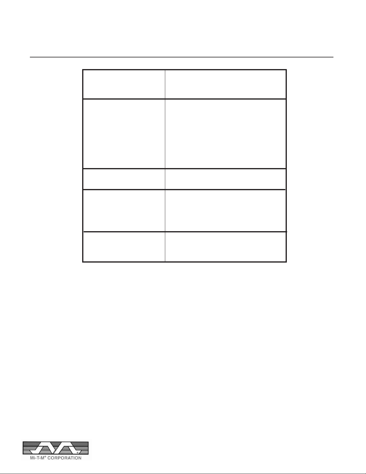
SPECIFICATIONS, FEATURES & OPTIONS
Electric Model Specifications
*Output temperatures are based on an input temperature of 55 deg. F
Pressure PSI - Steam – –
Pressures PSI - Press 2300 3000
Volume GPH - Steam – –
Volume GPM - Press 3.0 3.9
Water Flow Supply Rate @ 5 psi 6.0 8.0
Nozzle Size 4.0 4.5
Temperature Steam oC – –
Temperature Steam oF – –
Temperature Press oC 60 82
Temperature Press oF 140 180
Electric Motor - HP 5 7.5
POWER REQUIREMENTS
Volts (3 Phase) 575/460 575/460
Amps @ 575V 42 80
Amps @ 460V 51 125
KW 36 72
DIMENSIONS
Length 38 38
Width 21 21
Height 30 30
EH-2303-0M30 EH-3004-0M30
NOTES:
1. Standard features include CSA Inspection, auto start/stop, and 50' of hose.
2. Portability cart is optional
HOSE: Pressure washer hose is rated for 3000 psi and 250 F.
WATER PUMP: Three-Plunger high pressure pump with ceramic plungers
10
Page 11
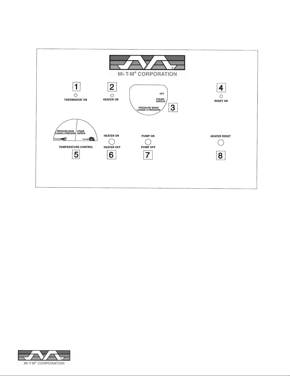
ELECTRICAL CONTROL PANEL
11
Page 12
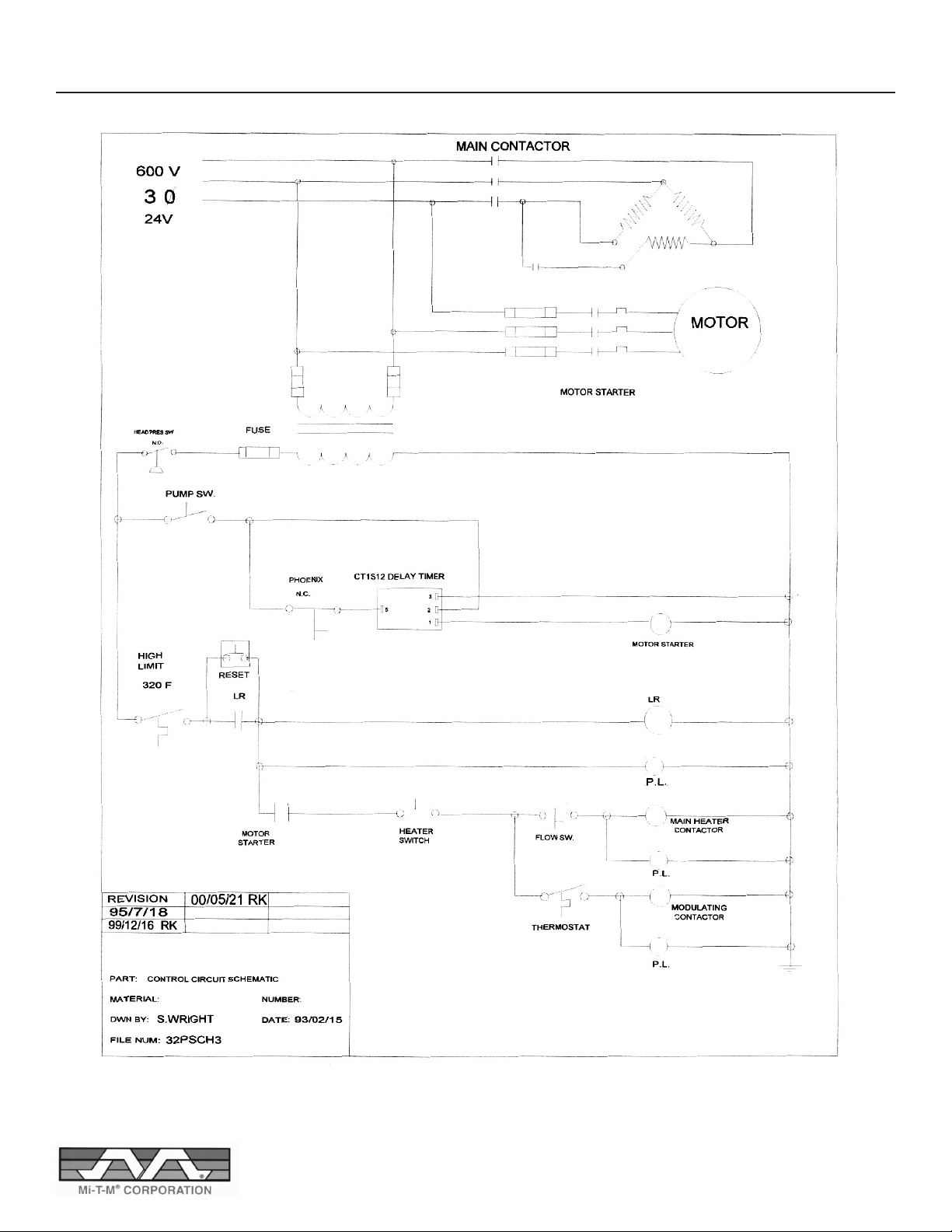
EH-2303-0M30 SCHEMATIC
12
Page 13
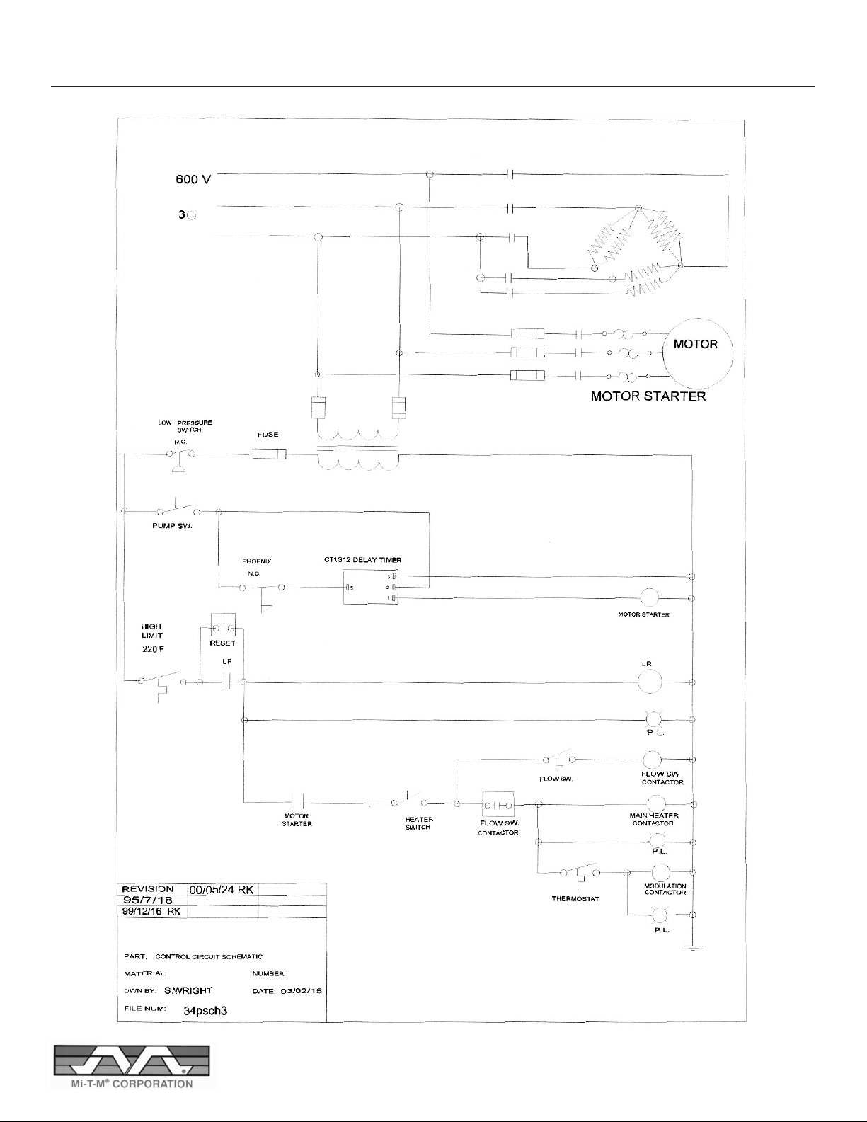
EH-3004-0M30 SCHEMATIC
13
Page 14
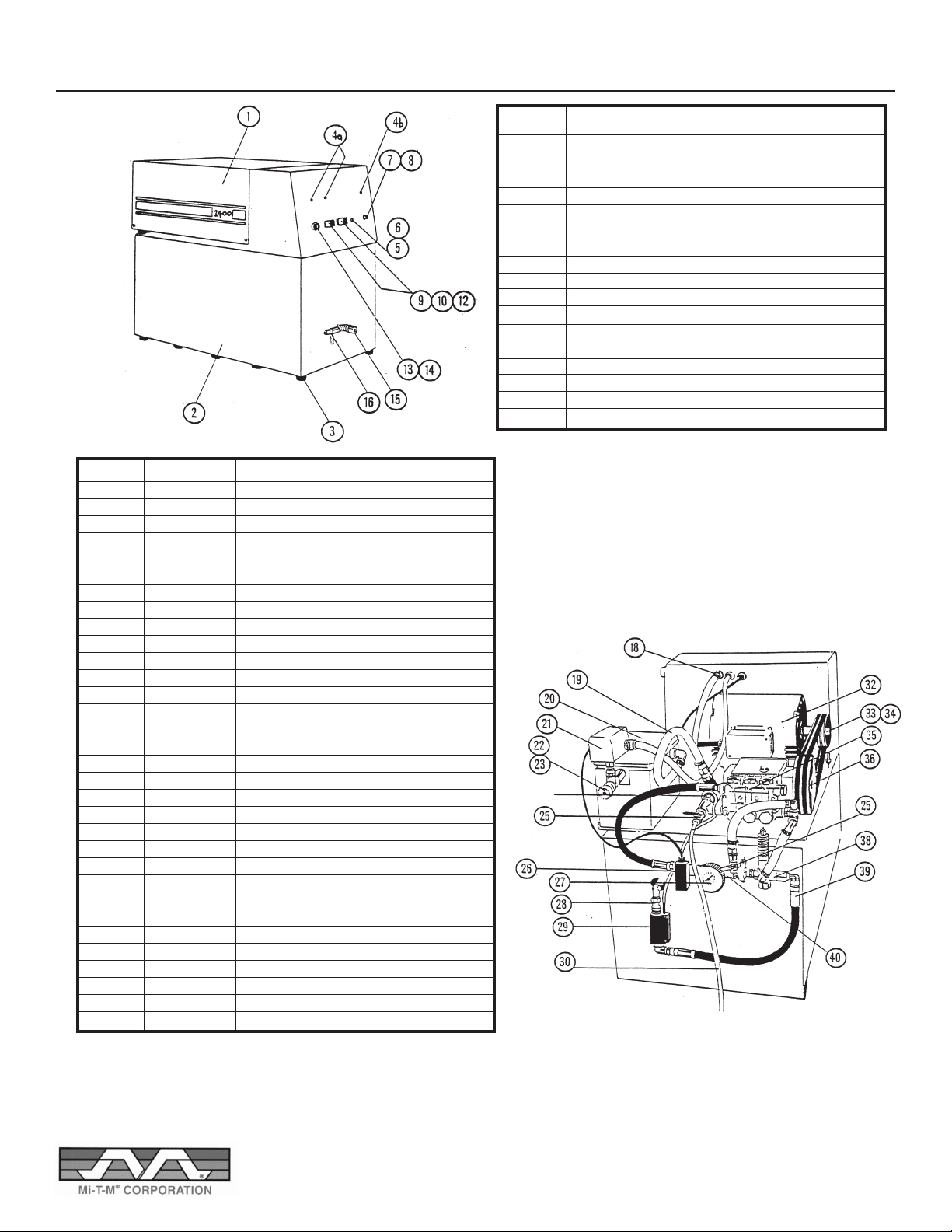
ELECTRICALLY HEATED PARTS BREAKDOWN
ITEM NO. PART NO. DESCRIPTION
18 EL: 3200 nylon strain relief
19 FI: PVC128 PVC bypass hose
20 EP: 15020 float box (optional)
21 EL: 69WR3 inlet pressure switch
22 FI: 201-W cap nut
23 EP: 22191 cap nut adapter
25 PU: CMVL brass valve chemical
26 EP: 33396 pressure switch
27 PU: HO25FF pressure gauge (optional)
28 FI: 66-6-6 swivel coupling
28 FI: 2501-6-6 3/8 FP X 3/8 JIC elbox
29 PU: ST5 flow switch
30 FI: JFT64 1/4" soapline tubing
32 EN: KH2 0.75 HP motor - 32S-36, 34S-36
32 EN: KH7 1.5 HP motor - 32P-34,32P-36,32PS-36
32 EN: KH22 5.0 HP motor-34P-36,34P-38.34P-72,34PS-72
32 EN: KH27 7.5 HP motor - 35P-72
33 DR: AK25 motor pulley - 1.5 HP, 0.75 HP
33 DR: AK44 motor pulley - 1.5 HP, 0.75 HP, 5 HP
33 DR: 2AK30 motor pulley - 5 HP
33 DR: 2AK30 motor pulley - 7.5 HP
35 T9961 General Pump - 32P-24,32P-36,32PS-36
35 TS1331 General Pump - 34P-36,34P-48,34PS-72
35 T1321 General Pump - 34P-72
35 TS2011 General Pump - 34P-72
36 PU:2PY140A24 Pump Pulley - T9961, TS1331, TS2011
36 PU:2PY160A24 Pump Pulley - T1321
36 DR:2AK30 Pump Pulley - T1321
36 DR:2AK49QT Pump Pulley - TS2011
38 PU: UVP1060 Unloader
39 FI: A48LD18 18" coil to panel hose
40 EP: 27570 manifold
ITEM NO. PART NO. DESCRIPTION
1 EP: 24751 Cover
2 EP: 24757 frame panels
3 FA: 315-006 rubber feet
4 EL: 2191L1-24V red pilot lights
4 EL: 2191L5-24V green pilot lights
5 EL: GGC5 1 1/4 fuses
6 EL: 345603 fuse holder
7 EL: 110PMOFF reset push button switch
8 EL: N3030 push button switch boot
9 EP: 703701 on/off plate
10 EL: 1131/26 pump toggle switch boot
11 EL: CA11 steam/pump select switch (optional)
12 EL: CA201-73 heater toggle switch
13 EL: TRV thermostat
14 EP: 40034 thermostat knob
15 EP: 22208 snap coupling
16 PU: SRI relief valve
14
Page 15
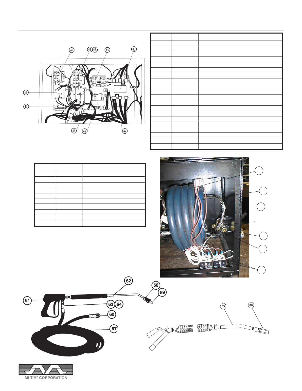
ELECTRICALLY HEATED PARTS BREAKDOWN
ITEM NO. PART NO. DESCRIPTION
41 EL: 45DG10AJ reset contactor & flow switch contactor
42 EL: S1210 motor starter - 35P-72
43 EL: T9EI overload relay
44 EL: ATDR15 motor circuit fuses
45 EL: 42DF35AJ heater contactor-P-36
45 EL: 42GE35AJ heater contactor-34P-72,34PS-72,34S-72,35P-72
46 EL: CT1S12 delay timer - all machines except 32S-36, 34S-72
47 EL:45DG10AJ thermostat contactor-32P-34,32P-36,32PS-36,34P-48
47 EL:45EG20AJ thermostat contactor-34P-72,34PS-72,34S-72,35P-72
48 EL:1492-CA1 terminal blocks
49 EL:MH50AG 600/24 volt transformer
50 EP:40176/40174 heater coil (outer) - 72 KW
51 EP:40173/40171 heater coil (inner) - 36 KW, 72 KW
51 EP:40179 575V heater coil (inner) - 48 KW
52 FI:2807-6-14 heater hoses 14"
52 FI: 2807-6-18 heater hose 18"
52 FI: 2807-6-36 heater hose 36"
54 EL: TRV high limit switch
55 EP: 50760 fuseable plug
56 EP: 40096 thermostat well bushing
ITEM NO. PART NO. DESCRIPTION
57 EL: 21186 50' hose
58 PU: ASN adjustable soap nozzle
59 1/4 MEG high pressure nozzle (see pg. 4 for size)
60 EP: 22209 snap plug
61 PU: G250V trigger gun
62 PU: Z9 lance
63 EP:22208 snap coupling
64 EP: 22209 snap plug
65 EP: 17130 Steam wand
65 EP: 17123 steam nozzle
50
51
52
27570
Manifold
56
55
54
15
Page 16
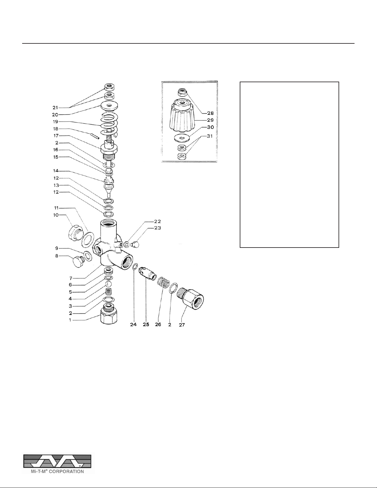
UNLOADER VALVE
UVP 1060
ITEM DESCRIPTION PART NUMBER
1 Inlet Fitting 60.0024.31
2 O Ring 10.3068.00
3 Ball spring 60.0015.51
4 S. S. Ball 14.7443.10
5 O Ring 10.3059.01
6 Seat 30.0011.51
7 Valve Housing 60.0020.35
8, 10 Plug 60.0028.31
9, 11 Washer 14.4042.00
12 Back Ring 10.4013.00
13 O Ring 10.3060.00
14 Piston Rod 60.0013.51
15 Back Ring 10.4008.01
16 O Ring 10.3055.00
17 Piston Housing 60.0014.31
18 Pin 153.1021.00
19 Spring 60.0032.61
20 Spring Guide 60.0011.31
21 Nut 11.4574.00
22 Washer 14.3911.00
23 Plug 28.0013.31
24 O Ring 10.3213.00
25 Check Valve 60.0017.31
26 Spring 60.0018.51
27 Outlet Fitting 60.0019.31
28 Nut 11.4589.10
29 Handle 60.027.22
30 Washer 14.3720.40
16
Page 17
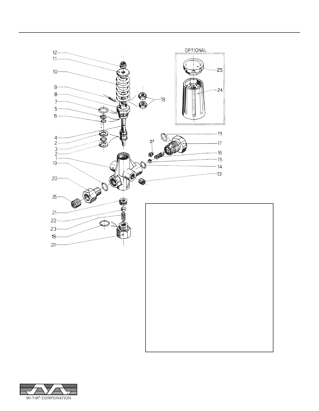
UNLOADER - MTM
Part # Code Description No.
1 OT354127 Cental Body 1
2 BK400111 Ring Antiextrusion SR111 2
3 OR403043 O-Ring 3043 NBR 1
4 IX402552 Threaded Stelo M8x1 L.94 1
4 IX384244/1 Threaded Stelo M8x1 L.115 1
5 BK400109 Ring Antiextrusion SR109 1
6 OR400272 Connecting O-Ring 0272 NBR 1
7 OR403062 Connecting O-Ring 3062 NBR 1
8 OT402549 Connector M18x1 1
9 SE406873 Pin 3x14 1
10 M0354240 Spring 120 1
10 M0354241 Spring 180 1
11 OT402550 Spring Plate 1
12 Vl387473 Nut. M8x1 1
13 OT354458 Cap G 1/4 1
14 OR350112 O-Ring Viton 112 1
15 SF351332 Ball 13/32” AISI 440 1
16 M0354676/1 Spring Inox 1
17 OT384674 Connector Guide Ball 1
18 Vl355588/1 Nut M8x1 Zinc 2
19 OR400117 O-Ring 0117 NBR 3
20 OT402554 Connector G 3/8 2
21 IX402553 Ball 1
22 SF230000 Ball 11/32” AISI 440 1
23 M0400001 Spring 1
24 MA350000/1 Knob 1
25 PL354152 Knob Cover 1
26 OT354457 Cap G 3/8 1
27 OT355293 Plate Ball 1
Note: Kit 00035150 includes: Part# 2,3,5,6,7,9,14,15,16,18,19,21,22,23,27)
17
Page 18
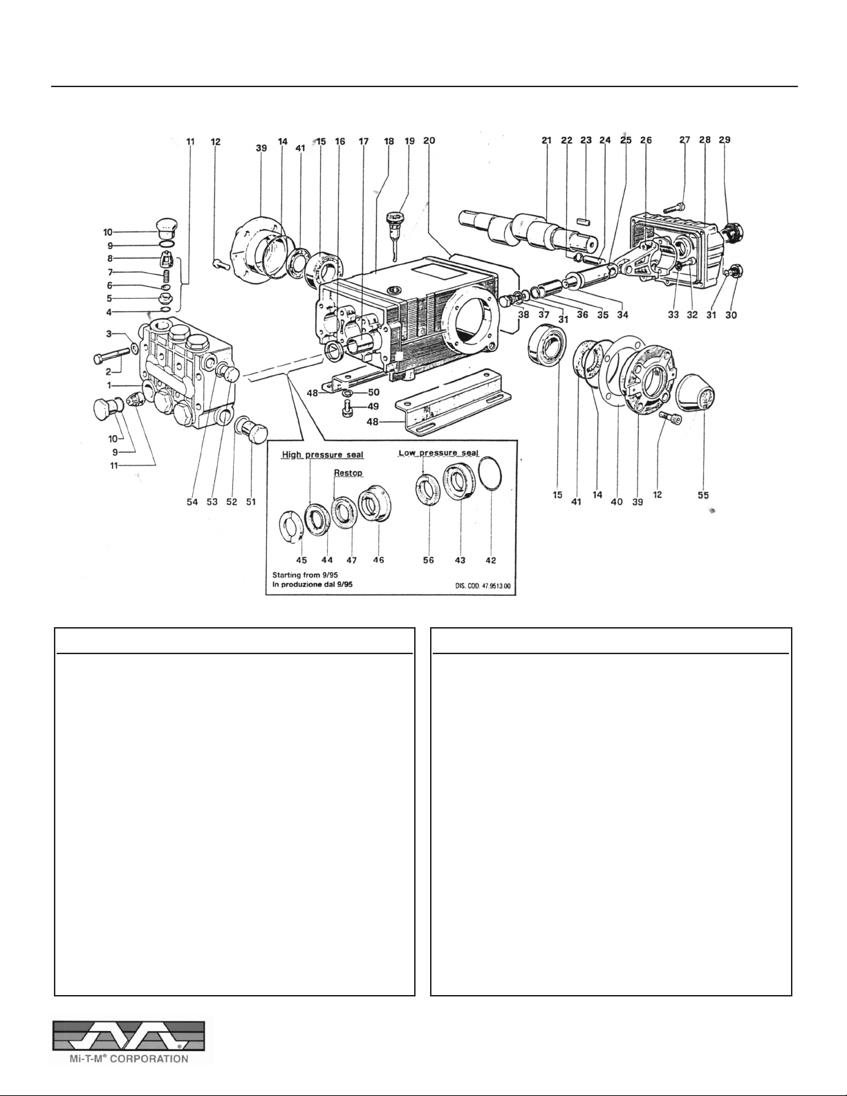
GENERAL PUMP TS1331
ITEM DESCRIPTION PART # QTY INCLUDED
IN KIT
1 Pump Head 47.1208.41 1
2 Screws 99.3206.00 8
3 Washers 96.7020.00 8
4 O-Rings 90.3841.00 6 1
5 Valve Seals 36.2003.66 6 1
6 Valve Plates 36.2001.76 6 1
7 Springs 94.7376.00 6 1
8 Valve Guides 36.2002.51 6 1
9 O-Rings 90.3847.00 6 5
10 Caps 98.2220.00 6 5
11 Valve Assembly 36.7032.01 6 1
12 Screws 99.3039.00 8
14 O-Rings 90.3913.00 2
15 Tapered Roller Bearings 91.8375.00 2
16 Oil Seals 90.1625.00 3 2
17 Bushings 90.9126.00 3
18 Crankcase 47.0104.22 1
19 Oil Dip Stick 98.2106.00 1
20 Cover Gasket 90.3922.00 1
21 Crankshaft - T1331 47.0204.35 1
22 Snap Rings 90.0557.00 6
23 Key 91.4878.00 1
24 Wrist Pins 97.7380.00 3
25 Piston Guides 47.0505.54 3
26 Connection Rods 47.0300.01 3
27 Screws 99.1837.00 5
28 Rear Crankcase Cover 47.1601.22 1
29 Oil Level Indicator 97.5968.00 1
ITEM DESCRIPTION PART # QTY INCLUDED
IN KIT
30 Cap 98.2041.00 1
31 O-Rings 90.3585.00 4 6
32 Screws 99.3099.00 6
33 Washers 96.7014.00 6
34 Washers 96.7286.00 3 6
35 Pistons 47.0404.09 3
36 Anti-Extrusion Rings 90.5067.00 3 6
37 Washers 96.7280.00 3 6
38 Piston Screws 47.2195.66 3 6
39 Side Crankcase Cover 47.1500.22 1
40 Shims 97.5678.00 2
41 Oil Seal 90.1648.00 1 3
42 Oil Rings 90.3616.00 3 28
43 Packing Retainers 47.0805.70 3 28
44 Packings 90.2705.00 6 8 & 28
45 Head Rings 46.1000.51 6 7 & 28
46 Intermediate Rings 47.2169.70 3 9 & 28
47 “Long Life” Rings 90.2704.00 3 9 & 28
48 Pump Feet 47.2000.74 2
49 Screws 99.3644.00 4
50 Washers 96.7106.00 4
51 Cap 98.2176.00 1
52 Washer 96.7514.00 1
53 Cap 98.2100.00 1
54 Washer 96.7380.00 1
55 Cover Cap 47.2124.51 1
56 Packings 90.2710.00 3 29 & 148
18
Page 19
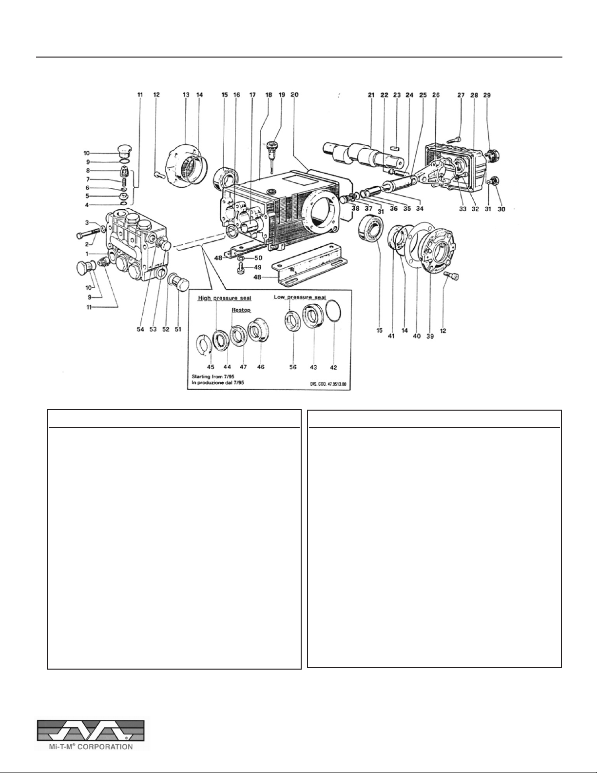
GENERAL PUMP T2011
ITEM DESCRIPTION PART # QTY INCLUDED
IN KIT
1 Pump Head 47.1209.41 1
2 Screws 99.3206.00 8
3 Washers 96.7020.00 8
4 O-Rings 90.3841.00 6 1
5 Valve Seats 36.2003.66 6 1
6 Valve 36.2001.76 6 1
7 Springs 94.7376.00 6 1
8 Valve Guides 36.2002.51 6 1
9 O-Rings 90.3847.00 6 5
10 Caps 98.2222.00 6 5
11 Valve Assembly 36.7032.01 6 1
12 Screws 99.3039.00 8
13 Crankcase Cover 47.1501.22 1
14 O-Rings 90.3913.00 2
15 Tapered Roller Bearings91.8375.00 2
16 Oil Seals 90.1625.00 3 2
17 Bushings 90.9126.00 3
18 Crankcase 47.0104.22 1
19 Oil Dip Stick 98.2106.00 1
20 Cover Gasket 90.3922.00 1
21 Crankshaft - TS2011 47.0206.35 1
22 Snap Rings 90.0557.00 6
23 Key 91.4878.00 1
24 Wrist Pins 97.7380.00 3
25 Piston Guides 47.0503.56 3
26 Connection Rods 47.0300.01 3
27 Screws 99.1912.00 5
28 Rear Crankcase Cover 47.1601.22 1
ITEM DESCRIPTION PART # QTY INCLUDED
IN KIT
29 Oil Level Indicator 97.5968.00 1
30 Cap 98.2041.00 1
31 O-Rings 90.3585.00 4 6
32 Screws 99.3099.00 6
33 Washers 96.7014.00 6
34 Washers 96.7286.00 3 6
35 Pistons 47.0404.09 3
36 Anti-Extrusion Rings 90.5067.00 3 6
37 Washers 96.7280.00 3 6
38 Piston Screws 47.2195.66 3 6
39 Side Crankcase Cover 47.1500.22 1
40 Shims 97.5678.00 2
41 Oil Seal 90.1648.00 1 3
42 Oil Rings 90.3616.00 3 28
43 Packing Retainers 47.0805.70 3 28
44 Packings 90.2705.00 6 8 & 28
45 Head Rings 46.1000.51 6 7 & 28
46 Intermediate Rings 47.2169.70 3 9 & 28
47 “Long Life” Rings 90.2704.00 3 9 & 28
48 Pump Feet 47.2000.74 2
49 Screws 99.3644.00 4
50 Washers 96.7106.00 4
51 Cap 98.2176.00 1
52 Washer 96.7514.00 1
53 Cap 98.2100.00 1
54 Washer 96.7380.00 1
56 Packings 90.2710.00 3 28 & 69
19
Page 20
TROUBLESHOOTING
TROUBLE POSSIBLE CAUSE REMEDY
Low Pressure Loose belt on pump Tighten pump
Leaks in water system Tighten all fittings
Insufficient water supply Fill tank or increase line size to machine
Outlet orifice worn or wrong size Replace with correct orifice.
CAUTION: Do not use smaller than
recommended. Excessive pressure will damage pump.
Gun control unloader valve Repair or replace unloader valve
bypass leak
Dirty or worn check valves Replace or clean. Refer to high
in pump pressure pump manual.
Cylinder cups leaking and/or Replace. Refer to high pressure
worn cylinder sleeves pump manual.
Excessive Outlet orifice restricted Remove orifice at tip of gun and clean.
Pressure Flush coil with water before replacing.
Scale or dirt in coils Descale coils
Pump speed too high Check water output GPM
Relief Valve Relief valve set at low pressure Re-adjust relief valve
Operates
Relief valve dripping Replace valve
after adjustment
Unloader valve stuck Repair unloader valve
Weak or no Clogged soap screens Clean or replace
chemical at nozzle
Air leak around soap siphon Tighten all fittings and tubings
check valve and/or metering
valve leaking
Pump motor Motor wet Allow to dry. Have motor checked
heating or overloading by qualified repair station.
Pump motor heating Outlet orifice restricted Remove orifice at tip of gun or overloading
and clean.
Undersize outlet orifice Replace with correct size
Coil scaling up Descale coil
Water pump out of oil Fill to correct level. Check for leaks
Overload switch operated Allow motor to cool CAUTION:
Switch may automatically reset.
Faulty motor Repair or replace
Water temperature Thermostat adjustment Adjust the thermostat to desired temperature
too low
Coils liming up Descale
20
Page 21

MI-T-M® WARRANTY
Warranty does not include damage from negligence, abuse or freezing and is limited to the
repair or replacement of the part(s).
Warranty parts(s) will be repaired or replaced F. O. B. our factory or at any Mi-T-M® authorized
depot, without charge, providing permission is first obtained from our factory and the part(s)
returned prepaid. If on site inspection is requested, a labour charge will apply.
All parts will be repaired or replaced at Mi-T-M® discretion.
WARRANTY PERIOD LABOR
PUMP - oil end 2 years 1 year
- manifold 2 years 1 year
- wet end No warranty No labor
(includes ‘o’ rings, packing and valves)
MOTOR / ENGINE Original Manufacturer’s Warranty
FABRICATED PARTS 1 year 1 year
(coil wrap, handle, frame, belt guard, etc.)
BURNER 1 year 1 year
TRANSFORMER 1 year 1 year
MISCELLANEOUS 1 year 1 year
(cords, floats, electrodes, switches, fuel pumps, thermostats, blower fans etc.)
UNLOADER 90 days 90 days
CONTROL & SAFETY SWITCHES 90 days 90 days
WEAR ITEMS No Warranty No Labor
(belts, hose, gun, wand, nozzle, quick couplers, ‘o’ rings, seals, gaskets, filters, chemical injectors, etc.)
HEAT EXCHANGE COIL
Schedule 40 2 years 1 year
Schedule 80 3 years 1 year
Electric 3 years 1 year
Any replacement during the warranty period will have a warranty of one (1) year or the balance of the
original warranty, whichever is greater.
Mi-T-M
misuse such as: 1. freezing
2. lime deposit
3. other foreign material deposit
4. shock or vibration.
®
will not replace coils under warranty if the coils have been subjected to
21
Page 22

222324
Page 23

Page 24

 Loading...