

Mitel Networks RFP47DRC, RFP4445 User Manual
OM Management Portal (OMP)
The tasks you can perform in the XML applications menu are mode-dependant.
Configuration mode Monitor mode See section
Create: Create new XML hooks 6.12.8.1
Configure: Configure selected XML hook in
6.12.8.2
detail panel
Show details: Shows selected XML
6.12.8.3
hook in detail panel
Delete: Delete selected XML hook 6.12.8.4
6.12.8.1 Creating a New XML Hook
In addition to the 15 predefined XML hooks, you can create up to 10 additional XML hooks. You can only
add XML hooks in Configuration Mode.
To add an XML hook, do the following:
1 In the Tasks bar click on Create.
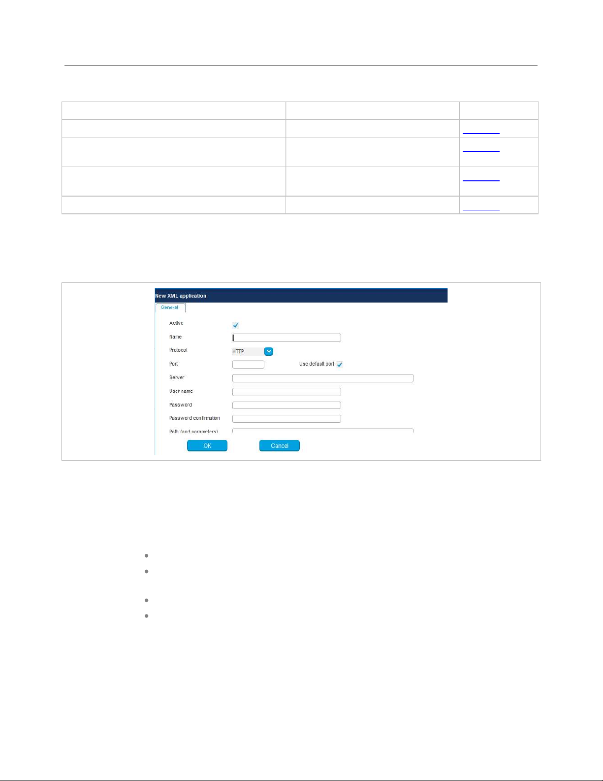
The New XML application panel opens.
2 Specify values for the following XML hook parameters:
Active: This setting activates or deactivates a configured XML application entry.
Name: The predefined hooks have fixed predefined names. A name must be
configured for the free defined hooks.
Protocol: Select the protocol HTTP or HTTPS.
Server: Enter the IP address or the name of the server which provides the XML
content.
Note: SIP-DECT 6.0 and later supports “SIPProxy” placeholders for
XML Server application URLs within SIP redundancy setups. In
cases where applications are located on a SIP server, it is
necessary to address XML applications by using the current
primary, secondary or tertiary SIP server address. In those
cases, the “SIPProxy” placeholder can be used as server input.
201

SIP-DECT OM System Manual
User name: Enter the login user name if an authentication is required by the
server.
Password, Password confirmation: Enter the password if the authentication is
required by the server.
Path (and parameter): Enter the path and query of the URI. For “Feature access
codes translation”, the Path settings contains placeholders for the queried
translation: {subsc} = Number, {ppn} = Device ID, {fac} = FAC.
3 Click OK to save your changes.
6.12.8.2 Modifying an XML Hook
You can only modify XML hooks in Configuration Mode.
To change the configuration of an existing XML hook, do the following:
1 Select the appropriate XML hook in the table.
2 In the Tasks bar, click Configure.
3 Edit the XML application parameters (described above) as necessary. You cannot change the name
of a predefined XML hook.
Note: SIP-DECT 7.0 and later supports centralized call logs for
systems using the MX-ONE call server. To enable this feature,
you must enter ”CSIntegration?object=history" as the value for
the Path parameter. This applies to both the Caller list and
Redial list predefined XML hooks.
See the description comment in chapter 5.9.5.
4 Click OK.
6.12.8.3 Viewing XML Hook Details
You can view the configuration of an XML hook in Monitor Mode. Do the following:
1 Select the appropriate XML hook in the table.
2 In the Tasks bar click on the Show details command.
The user account data is displayed in the user account detail panel.
3 Click Cancel to close the XML hook detail panel.
6.12.8.4 Deleting XML Hooks
You can only delete XML hooks in Configuration Mode. You cannot delete any predefined XML hooks.
To delete an XML hook, do the following:
1 Select the appropriate XML hook(s) in the table by activating the corresponding checkbox(es).
2 In the Tasks bar, click Delete.
A confirmation dialog opens.
3 Click OK to confirm.
202
OM Management Portal (OMP)
6.12.9 “COA PROFILES” MENU
SIP-DECT 6.0 and later supports central configuration over the air (CoA) for Mitel 602 DECT phones.
The CoA profiles page lists the available CoA profiles that can be downloaded to the DECT phones.
Note: The profiles generated by the user_common.cfg configuration file
are also listed in this window. When managed with OMP, they
can be overwritten when the user_common.cfg configuration file
is reloaded. The maximum download size is 4kB.
You can import CoA profiles via the CoA Profiles menu. Once you have imported the profiles, you can
assign them to specific DECT phone users.
To create a new CoA profile:
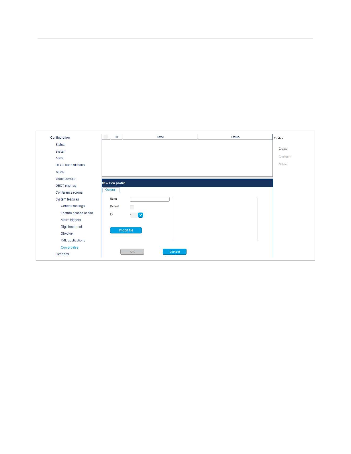
1 Click Create under the Tasks list on the right-hand side of the CoA profiles window.
The New CoA profile dialog opens.
2 Configure the settings for the CoA profile:
- Name: Specify a name for the CoA profile
- Default: Indicate whether this is the default CoA profile to be used
- ID: Select an ID for the CoA profile from the drop-down menu.
3 Click Import file to select the CoA file to import.
The CoA profiles page displays the new CoA profile in the table.
203

SIP-DECT OM System Manual
6.13 “LICENSES” MENU
The Licenses pageprovides an overview of licenses currently in use. In Configuration Mode, you can
also import a license file.
The license information is displayed in the following tabs:
Status: Shows general license information.
License file: Allows import of a license file.
System: Shows system license status.
Messaging: Shows Integrated Messaging and Alerting Service (IMA) license status.
Locating: Shows Locating license status.
“General” tab
The General tab displays general information about the current system license.
“License file” tab
The License file tab allows you to import a license file (only possible in Configuration Mode).
1 Click the File button to select the path and file name where the license file is stored.
2 Click the Import button.
“System” tab
The “System” tab provides OM System license information. This includes supported software version
and number of licensed DECT base stations (RFPs) compared to number of connected DECT base
stations.
“Messaging” tab
The “Messaging” tab provides OM Messaging and Alerting license information.
“Locating” tab
The “Locating” tab provides OM Locating license information.
204
OM Management Portal (OMP)
6.14 “GENERAL” MENU
The General menu is available in all program situations. It contains following submenus:
Exit: Selecting this menu entry opens the exit dialog to close the OMP.
Options: Selecting this menu entry opens the Options dialog (see below).
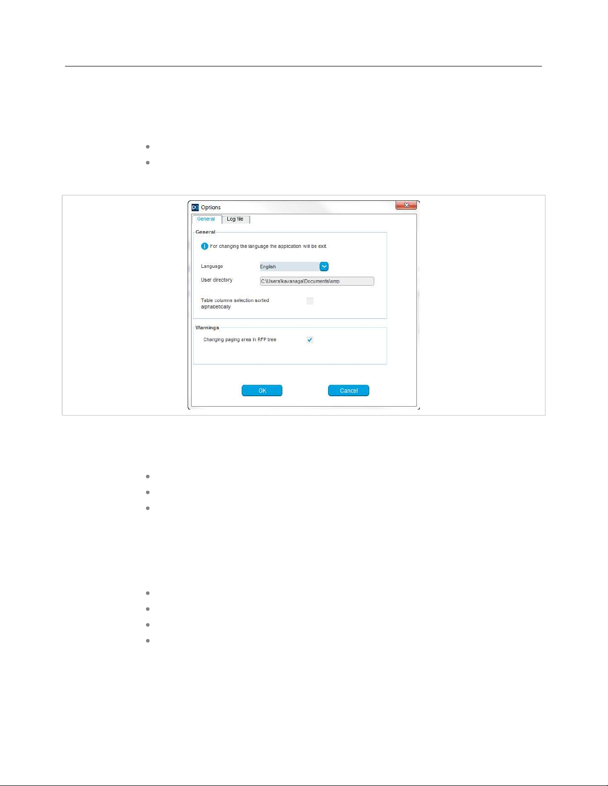
“Options” - “General” tab
Language: You can select the OMP language. After changing the language, the OMP is automatically
closed and must be started again.
The field User directory shows the path where the following files are saved if necessary:
System dump file “sys_dump.txt”
Expert console log file “spy.log” when the application terminates
Exception log file “spy_trace_<date>_pxxx” in case of a Java exception, file name
extension “xxx” ranges from 000 to 999
In the Warnings section you can activate/deactivate the display of warning messages in the OMP.
Notes on log files
The mechanism for creating the log files is the same as the PC OMM spy log mechanism, what means:
The maximum size of the log file is 1 GB
1000 log files per day at maximum
Only the 30 newest created log files are kept, older ones are removed automatically
Log files older than 6 days are removed
205

SIP-DECT OM System Manual
“Options” - “Log file” tab
In the Log file tab you can enable several trace levels.
6.15 “HELP” MENU
The Help menu is available in all program situations. It contains following submenus:
Info: Selecting this menu entry displays the End User License Agreement (EULA).
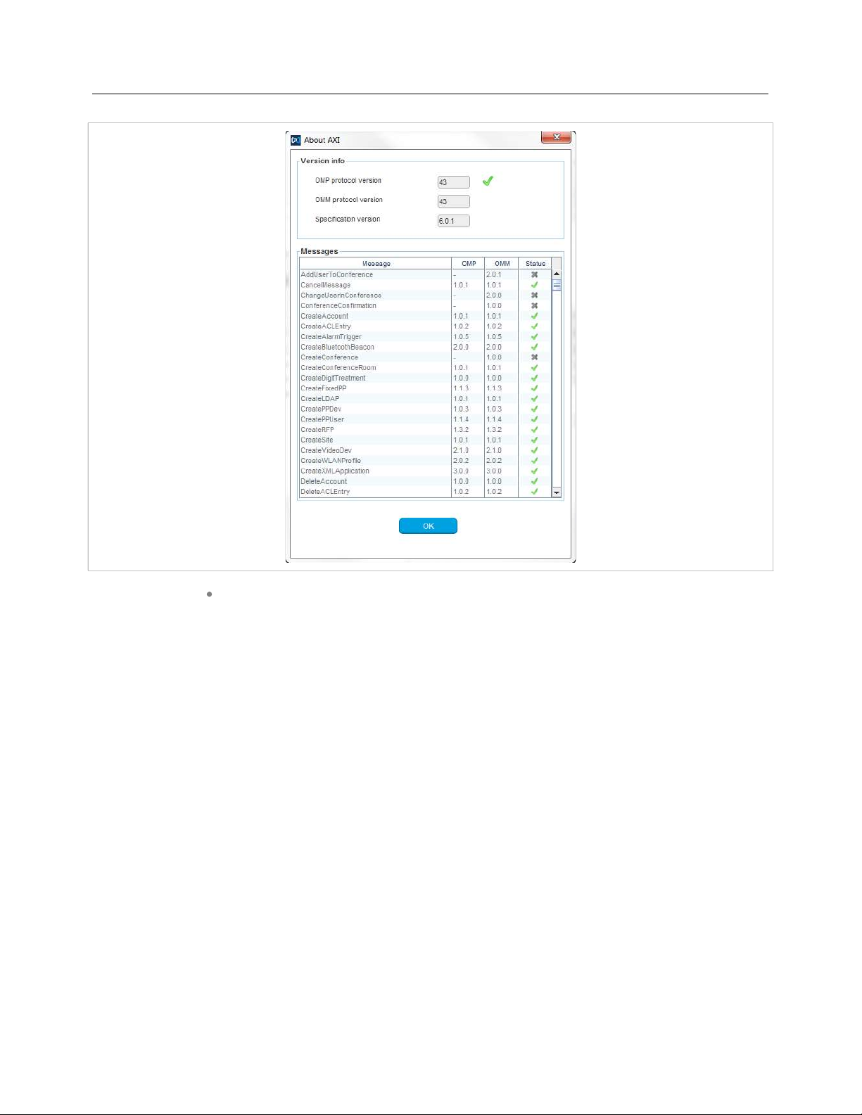
About AXI: Selecting this menu entry displays the About AXI dialog. This dialog
compares the protocol version numbers which are provided by the OMM with the
protocol version numbers supported by the OMP. The warning icons or show
a version mismatch. A version number “-” means the protocol element is not used
by OMP.
206
OM Management Portal (OMP)
About OMP: Selecting this menu entry displays the OMP version info and copyright.
207

SIP-DECT OM System Manual
7 DECT PHONE
The DECT phone has a special system menu for administration of the DECT system.
7.1 KEY LOCK WITH PIN
7.1.1 MAINTAIN THE PIN
The PIN is used to allow access to the Security menu and to lock the phone. The user can adjust his PIN
and the feature Key lock with PIN here: System menu/Administration.
The submenu “Key lock” is hidden if the feature is disabled.
The update to SIP-DECT 7.1SP1 causes a reset of the DECT phone key lock PIN to default “0000”.
7.1.2 UNLOCK A LOCKED MITEL 600 DECT PHONE
As of SIP-DECT 8.0 and DECT phone SW 7.2, the DECT phone can be reset to factory defaults if the
DECT phone is protected with a PIN, and no other option can be used to unlock the phone; for example,
set the PIN through the OMM to a defined value.
If a wrong PIN are successively entered 3 times, then a reset procedure can be activated by entering the
code “***778#”.
208

DECT Phone
The reset procedure requests the password “Master” to reset all data on the phone, which also removes
the subscription and the PIN lock.
The DECT phone needs to be subscribed with a DECT system after the reset.
Note: Be aware that the Master reset deletes all data from the DECT phone.
209

SIP-DECT OM System Manual
Long press of the
Select the lock key
7.1.3 SETUP AUTOMATIC KEY LOCK WITH PIN
The following pictures show an example how to turn off the DECT phone key lock with PIN through the
Mitel 600d DECT Phone UI.
and enter the PIN
to unlock the
phone
Option to change
the PIN
option soft key
opens the
system menu
Option to change
the key lock
parameter
Select
Administration
Time for the
automatic key lock
is set to 120
seconds
Select Key lock
Off and various
timer values are
available
Choose the
desired value, for
example, Off and
confirm with OK
The update to SIP-DECT 7.1SP1 causes a reset of the DECT phone key lock PIN to default “0000”.
210
Confirmation that
the chosen values
is stored
Key lock with PIN
is Turned Off
Configuration and Administration
8 CONFIGURATION AND ADMINISTRATION
This section provides detailed information on various configuration and administration aspects of the
SIP-DECT solution.
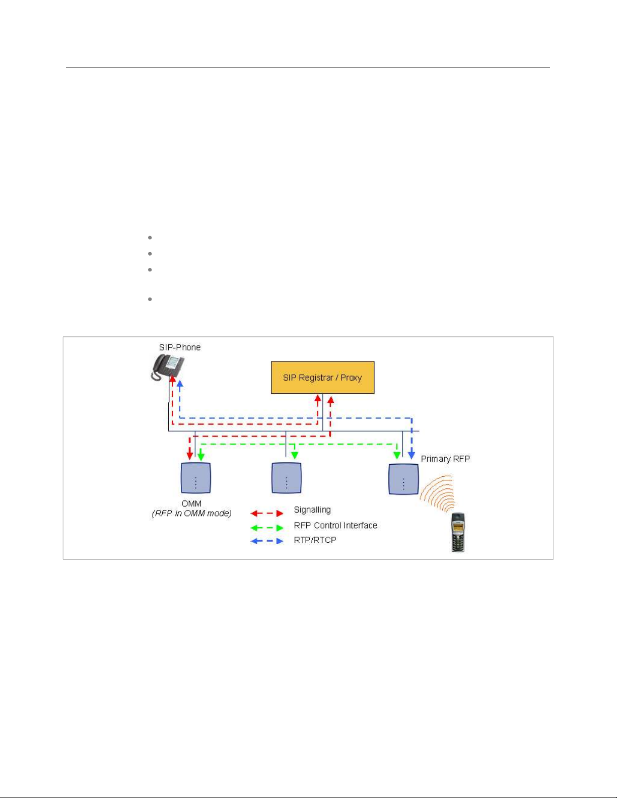
8.1 IP SIGNALING AND MEDIA STREAM
To establish a call between an IP Phone and a DECT phone (for example, Mitel 600), the following IP
streams must be established:
A signaling channel to and from the SIP phone.
A signaling channel to and from the OMM.
A control interface between the OMM and the RFP that has a connection to the
DECT phone (known as the primary RFP).
A Real Time Protocol (RTP) / Real Time Control Protocol (RTCP) connection
between the SIP phone and the primary RFP.
The following figure illustrates this scenario.
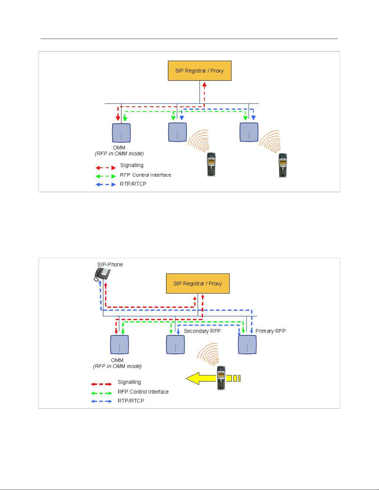
To establish a call between two DECT phones, the same IP streams must be established like in the
scenario before, except the IP phone is not involved. The following figure illustrates this scenario.
211
SIP-DECT OM System Manual
A call from one DECT phone to another that resides on the same RFP will loop back within the RFP if no
media gateway is involved. So the call will not pass through to the Local Area Network (LAN). Although
the voice packets will not impact LAN traffic, signal packets will.
If the DECT phone user is moving, the DECT phone detects that another RFP has a better signal
strength and, therefore, it starts the handover process. The media stream from the IP phone cannot
move to the secondary RFP, so the primary RFP uses the LAN to direct the voice to the secondary RFP,
as shown in the following figure.
As the DECT phone user moves into the next RFP zone of coverage, the DECT phone detects that the
RFP has a better signal strength. Again the media stream from the SIP phone cannot move to the
secondary RFP, so the primary RFP uses the LAN to direct the voice to the new secondary RFP.
212

Configuration and Administration
8.2 DECT BASE STATION SYNCHRONIZATION
To guarantee a seamless handover if a caller moves from one DECT base station zone of coverage to
another DECT base station zone of coverage, an accurate synchronization of the DECT base stations is
necessary.
The DECT base stations are synchronized over the air interface. The first DECT base station to
complete startup transmits a signal on the air for the other DECT base stations to synchronize from. If a
DECT base station gets in sync, it transmits a signal on the air and becomes the sync source for the next
DECT base station. Only DECT base stations that can receive a synchronization signal become
synchronized.
For the DECT base station to sync to another DECT base station, the signal strength cannot drop below
-70 dBm. You must consider this requirement during the site survey.
As long as a DECT base station is not in sync, no calls can be established using this DECT base station.
If a DECT base station loses the synchronization, the DECT base station does not accept new calls
(“busy bit”). There is a delay of maximum 3 minutes until the active calls on this DECT base station are
finished. Then it tries to get synchronized again.
213

SIP-DECT OM System Manual
A SIP-DECT installation is more reliable if a DECT base station can receive the signal from more than
only one DECT base station because the other signals are also used for synchronization.
The sync-over-air solution is very reliable because all existing redundant paths are used for
synchronization. Thus, hardware tolerances have only very little influence. No DECT base station has a
key position. Only unfavorable setups without redundant synchronization paths can cause problems.
Sometimes DECT base stations do not need to be synchronized (e.g. if they are in different buildings).
These DECT base stations can be put into different clusters. DECT base stations in different clusters are
not synchronized with each other. Different clusters start up at the same time independently.
8.2.1 INITIAL SYNCHRONIZATION PROCEDURE
To avoid synchronization problems and to speed up the synchronization on system startup, an initial
synchronization procedure is used. For every cluster the following synchronization stages are defined.
Synchronization stage 0
– If at least one preferred DECT base station was configured, the
synchronization process waits up to 30 seconds for an incoming startup
message of such a preferred DECT base station. Receiving a message will
finishing stage 0 and the synchronization process jumps to stage 1.
– If no message is received within 30 seconds, this stage will be terminated and
the next stage begins.
– If no preferred DECT base station was configured, this stage is ignored.
Synchronization stage 1
– If a preferred DECT base station was determined in stage 0, this one becomes
the synchronization source for the subsequent DECT base stations. Otherwise
214

Configuration and Administration
the first DECT base station that sends a startup message becomes the
synchronization source for the subsequent DECT base stations.
– In this stage, only DECT base stations reporting an RSSI value better than
-65 dBm are permitted to perform synchronization.
– If a DECT base station has completede its synchronization, this DECT base
station will be also a synchronization source for other upcoming DECT base
stations.
– The initial timeout for this stage is 30 seconds. Whenever a DECT base station
has finished its synchronization in this stage a new stage timeout value is
calculated.
– If no DECT base station comes up within the timeout time or if all the upcoming
DECT base stations do not fit the RSSI threshold, this stage will be terminated
and the next stage begins.
Synchronization stage 2
– The behavior of this stage is identical to stage 1, but an RSSI threshold value
of -70 dBm is significant.
Synchronization stage 3
– The behavior of this stage is identical to stage 1, but an RSSI threshold value
of -75 dBm is significant.
Synchronization finished
– No more RSSI threshold value is significant. All DECT base stations that failed
the stage conditions above are now permitted to perform synchronization.
The last level “synchronization finished” will be achieved either all registered DECT base stations of this
cluster are synchronized or the timer of stage 3 expires.
8.2.2 CHECKING THE SYNCHRONIZATION OF A NETWORK
For every cluster a periodically check of the synchronization of the network is done. If the network is split
into at least two subnets, all the RFPs of the lesser subnet(s) will be resynchronized. While doing initial
synchronization procedure this check is deactivated. You can check the DECT base station
synchronization from the Sync view menu of the OM Management Portal (OMP), see section 6.7.6.
8.3 DECT BASE STATION CHANNEL CAPACITY
The DECT base station has 12 available time slots on air; eight can have associated DSP/media
resources for media streams. All DECT time slots are used for control signaling, software download over
air, messaging and bearer handover independent of associated DSP/media resources.
If all eight media stream channels are used, the DECT base station announces a “busy bit”. In that case,
the DECT phones determine whether another DECT base station has an appropriate signal strength. If
so, the DECT phone performs a handover to that DECT base station. Once the handover is complete,
the DECT base station lowers its “busy bit”.
Whenever the busy state is announced a log entry is made to the system logs. If the announcement of
busy raises in a specific area, an additional DECT base station should be installed to double the number
of media streams available for calls.
215

SIP-DECT OM System Manual
Notes on Hi-Q connections
Each Hi-Q connection uses twice the capacity of conventional narrowband on the DECT air interface.
Due to this fact, four Hi-Q connections (instead of eight) can be established via one DECT base station.
It is not possible to have DECT XQ audio combined with Hi-Q audio within the same connection.
8.4 NETWORK INFRASTRUCTURE PREREQUISITES
To establish and maintain an SIP-DECT installation, a network infrastructure is assumed, which
comprises at least the following components:
DECT base stations
DECT phones
IP PBX/media server (for example, Asterisk)
TFTP server
Depending on the operational modes the following services should be provided:
DHCP
TFTP
SNTP
DNS
LDAP
Syslog daemon
Notes on network infrastructure prerequisites
In NA outdoor RFPs may only be installed with the antennas shipped with the units.
No other antennas or cabling are permitted. In EMEA the outdoor RFPs are shipped
without antennas and you may use the units with one of the optional antennas
(separate order no.).
A TFTP server is no longer required for boot of a 3rd or 4th generation RFPs.
TFTP, FTP(S), HTTP(S), SFTP are supported for 3rd or 4th generation RFPs
software update.
8.5 SIP-DECT STARTUP
This section contains detailed information on the startup (booting) process of the SIP-DECT solution.
For booting 2ndgeneration RFPs, there must be at least one TFTP server on the attached network to
load the OMM/RFP application software.
3rdor 4thgeneration RFPs uses the internal flash to start the boot image. A fileserver is only needed for
software update over the network.
216

Configuration and Administration
The essential network settings can be alternatively:
Communicated by a DHCP server at startup time.
Configured on the RFP with the OM Configurator tool (see section 7.6). The settings
made by the OM Configurator will be saved permanently in the internal flash
memory of each OMM/RFP.
8.5.1 TFTP AND DHCP SERVER REQUIREMENTS
TFTP server requirements
The DECT base station obtains the boot image file from a TFTP server. The requirement list for the used
TFTP server is defined as follows:
The support of RFC 1350 /1/ is mandatory.
To accelerate the download of a boot image file for older 2nd generation DECT base
stations, it is possible to increase the packet size of the transmitted TFTP packets
from 512 bytes per packet to 1468 bytes per packet. To use this optional feature,
the TFTP server must support RFC 2347 /3/ and RFC 2348 /4/.
To reduce the overall download time of the older 2nd generation DECT base
stations in a system, it is possible to use TFTP multicast download. To use this
optional feature, the TFTP server must support RFC 2090 /2/ and RFC 2349 /5/.
To use the TFTP multicast option, the attached network must support multicast too. Furthermore a
support of IGMP, RFC 2236 /6/ is required.
Note: If many DECT base stations loading the boot image
simultaneously, the network load could increase significant. To
balance the network load or for backup reasons, it is possible to
configure more than one TFTP server in a network.
DHCP server requirements
A DHCP server needs to support RFC 2131 /9/. The TFTP and DHCP server need not to reside on the
same host.
8.5.2 BOOTING STEPS
Booting is performed in two steps:
1 Starting the boot process.
2 Starting the application.
Booter startup
On startup each DECT base station tries to determine its own IP address and other settings of the IP
interface from the configuration settings in the internal flash memory. If no settings are available or these
settings are disabled, the DECT base station tries to determine these settings via DHCP. Depending on
the DECT base station type, the DECT base station software is to be loaded:
A 3rd generation DECT base station gets the application image from internal flash
memory.
217

SIP-DECT OM System Manual
An older 2nd generation DECT base station only has a small standalone application
built into the flash. This software realizes the so-called net boot process. The RFP
gets the application image file from the TFTP server.
Application startup
After starting the application image, the RFP software checks the local network settings in its internal
flash memory. If no settings are available or if they are disabled, the RFP software starts a DHCP client
to determine the IP address of the OMM and other application startup settings.
The RFP software acquires the OMM IP address:
within the local network settings if active
through DHCP request
DECT base station configuration file (see 8.7.7)
If the IP address of the actual RFP device matches one of the acquired OMM IP addresses, the DECT
base station software continues in OMM mode. Otherwise, the DECT base station runs as normal DECT
base station without OMM mode.
Note: Only 3rdgeneration DECT base stations are able to run in OMM
mode while older 2ndgeneration DECT base stations cannot
function as OMM.
8.5.3 BOOTER STARTUP
The SIP-DECT DECT base station software includes a booter with the following features:
VLAN can be configured via the OM Configurator without a static IP configuration.
This means that the first DHCP request will be done by using VLAN.
To balance the network load with older 2nd generation RFP devices, up to three
TFTP servers can be configured. This can be done using the OM Configurator (local
setting) or using the DHCP option 150. Before starting the download, the TFTP
server will be selected randomly by the booter. But, if the option “Preferred TFTP
server” was set by the OM Configurator, the option “TFTP server address” will
specify the TFTP server to use. No randomly selection will be done in this case.
Older 2nd generation RFPs only: to reduce the number of TFTP packets sent by the
TFTP server, the packet size can be increased. This will be done by using a TFTP
option (see 8.5.1 “TFTP server requirements”).
Older 2nd generation RFPs only: Multicast TFTP download is possible if the TFTP
server and the connected network support this.
To indicate the actual state of the booter, the LEDs of the RFP will be used (see
8.5.5).
8.5.3.1DHCP Client
Within the initial boot process the DHCP client supports the following parameters:
IP address mandatory
Net mask mandatory
Gateway mandatory
218

Configuration and Administration
Boot file name mandatory for older
RFPs
TFTP server mandatory for older
RFPs
Public option 224: “OpenMobility” / “OpenMobilitySIP-DECT” mandatory
VLAN-ID optional
TFTP server list optional
8.5.3.1.1 DHCP Request
The DHCP client sends the vendor class identifier (code 60) “OpenMobility3G” (3rdgeneration RFPs) or
“OpenMobility” (older 2ndgeneration RFPs) and requests the following options in the parameter request
list (code 55):
Subnet mask option (code 1)
Router option (code 3)
VLAN ID option (code 132)
TFTP server list (code 150)
Public option 224 (code 224) (string “OpenMobility” or “OpenMobilitySIP-DECT”)
Public option 225 (code 225) (VLAN ID, not relevant for SIP-DECT)
Public option 226 (code 226) (not relevant for SIP-DECT)
8.5.3.1.2 DHCP Offer
The DHCP client selects the DHCP server according to the following rules:
The public option 224 (code 224) has a value equal to the string “OpenMobility”,
or
The public option 224 (code 224) has a value equal to the string
“OpenMobilitySIP-DECT”.
If none of the two rules above match, the DHCP offer is ignored.
Information retrieved from the DHCP offer:
The IP address to use is taken from the yiaddr field in the DHCP message.
The IP net mask is taken from the subnet mask option (code 1).
The default gateway is taken from the router option (code 3).
The TFTP server IP address is taken from the siaddr field in the DHCP message
and additionally DHCP option 150, if available.
The boot image filename is taken from the file field in the DHCP message, if this
field is empty, the default filename is used.
8.5.3.1.3 Retries
If the DHCP client does not get an appropriate DHCP offer, a new DHCP request is send after 1 second.
After 3 DHCP requests are sent the DHCP client will sleep for 60 seconds. During this time the booter
accepts a local configuration with the OM Configurator.
219

SIP-DECT OM System Manual
This cycle repeats every 3 minutes until either all the required DHCP options are provided or the system
is manually configured using the OM Configurator tool.
8.5.3.2TFTP Client
The TFTP client will download the application image from the TFTP server. Both TFTP server and the
name of the application image are supplied via the DHCP client. The application image is checksum
protected.
Downloading the application image via TFTP is mandatory for older 2
nd
generation RFPs only. 3
rd
generation RFPs will load the application image from the internal flash, and (if configured) also download
the application image via TFTP for update.
8.5.3.3Booter Update
With older second generation RFPs, each application software image comes with the latest released
booter software. The application software will update the booter automatically. With third generation
RFPs, the booter will only be updated if you update the software.
If you downgrade the RFP’s application software image to an older release, the booter does not
downgrade automatically. In addition, if you want to use the OM Configurator tool (see 8.7), the OM
Configurator version must match the booter software version.
8.5.4 APPLICATION STARTUP
After successfully starting the application software, the DECT base station checks the local network
settings in its internal flash. If no settings are available or if they are disabled, it starts a DHCP client to
determine the IP address of the OMM and other application startup settings.
8.5.4.1DHCP Client
The DHCP client is capable of receiving broadcast and unicast DHCP replies. Therefore the flags field is
0x0000
(0xFF)
. The DHCP request contains the well-known magic cookie
.
(0x63825363)
Parameters
The following parameters are supported within this step:
Option / Field Meaning Mandatory
yiaddr IP address of the IP-RFP yes
siaddr Parameter named “Boot Server Host Name” with value as the
IP address of the TFTP server
file Parameter named “Bootfile Name” with value of the path
(optional) and name of the application image. For example
“iprfp3G.dnld“ (3
rd
generation RFPs) and “iprfp4G.dnld“ (4
generation RFPs), or “iprfp2G.tftp” (older 2ndgeneration
RFPs).
and the end option
no (3G/4G RFPs)
yes (older 2G RFPs)
no (3G/4G RFPs)
yes (older 2G RFPs)
th
option 1 Subnet mask no
option 3 Default Gateway no
option 6 Domain Name Server no
220

Configuration and Administration
6.1, this option was used for the RFP
Option / Field Meaning Mandatory
option 15 Domain Name no
option 42 IP address of a NTP server no
option 43 Vendor-specific options (see table below) yes
option 66 Provisioning URL for the OMM (ConfigURL). URL of an
no
external server that provides configuration files for the Base
Station(s) hosting the OMM.
Note: In SIP-DECT 2.1 Config file server. If you want to specify a URL for the RFP
Config file server, use option 233 instead.
option 132 VlanId no
option 150 TftpServerIpList no
option 224 Parameter named magic_str must be set to value
yes
"OpenMobility" or "OpenMobilitySIP-DECT".
option 226 Enabling 802.1X feature (set to 1). no
option 233 URL that specifies the protocol, server and path to access the
no
DECT base station configuration files (see section 7.9). For
SIP-DECT 6.1 or earlier, this option takes priority over option
66 when set.
option 234 Provisioning URL for the OMM (ConfigURL). URL of an
no
external server that provides configuration files for the Base
Station(s) hosting the OMM.
option 236 This mode value determines which instance (OMM, RFP)
no
shall use the given Provisioning URL (Option 43-2, 66 or 234).
Valid values are:
1. The RFP shall use the given Provisioning URL.
2. The OMM and RFP shall use the given Provisioning
URL.
Else: The OMM shall use the given Provisioning URL.
Vendor specific options
The Vendor Specific Options consist of:
Vendor Specific Option Meaning Length Mandatory
option 10 ommip1: Used to select the IP-RFP that hosts
option 14 syslogip: IP address of a Syslog Daemon 4 no
option 15 syslogport: Port of a Syslog Daemon 2 no
option 17
(SIP-DECT 5.0 and older)
the Open Mobility Manager (OMM).
Country: Used to select the country in which the
OMM resides. This enables country specific
tones (busy tone, dial tone, …).
4 yes
2 no
221

SIP-DECT OM System Manual
option 18
ntpservname: Name of a NTP Server x no
(SIP-DECT 5.0 and older)
option 19 ommip2: Used to select a secondary IP-RFP
4 no
that hosts the standby Open Mobility Manager
(OMM). This option must be included if the
OMM Standby feature is used (see section
7.15).
option 43 sub-option 1
(SIP-DECT 6.2 and later)
URL that specifies the protocol, server and path
to access the DECT base station configuration
no
files (see section 7.9).
option 43 sub-option 2 Provisioning URL for the OMM (ConfigURL).
no
URL of an external server that provides
configuration files for the Base Station(s)
hosting the OMM.
option 43 sub-option 226 Enable 802.1x feature (set to 1). 1 no
Example
An example of the minimal contents for the Option 43 parameter value would be:
0a 04 C0 A8 00 01 where “C0 A8 00 01” represents “192.168.0.1” for the OMM IP.
The option 43 contains a string of codes in hex the format is “option number” “length” “value” in this
example
0a = option 10 (ommip1)
04 = following value is 4 blocks long
C0 A8 00 01 = 192.168.0.1
If there is more than one option, add the next option at the end of the previous one. Depending of the
DHCP server you must end the option 43 with FF.
Country specific tones (SIP-DECT 5.0 and older ONLY)
Tones for the following countries are supported:
Country code Country Country code Country
1 Germany 15 Hungary
2 Great Britain 16 Poland
3 Switzerland 17 Belarus
4 Spain 18 Estonia
6 Italy 19 Latvia
7 Russia 20 Lithuania
8 Belgium 21 Ukraine
9 Netherlands 22 Norway
10 Czechoslovakia 24 Sweden
11 Austria 25 Taiwan
12 Denmark 100 North America
13 Slovakia 101 France
222

Configuration and Administration
14 Finland 102 Australia
8.5.4.2Configuration using DHCP
The DHCP client of the RFP family requests several parameters that are used to configure the RFP. The
DHCP client vendor class identifier (option 60) is different for the different RFP generations:
3rd generation RFPs (RFP 35/36/37 IP / RFP 43 WLAN) use “OpenMobility3G”.
4th generation RFPs (RFP 44/45/47 IP / RFP 48 WLAN) use “OpenMobility4G”.
Older 2nd generation RFPs (RFP 32/34 / RFP 42 WLAN use) “OpenMobility”.
BOOTP/DHCP
Meaning Type Remarks
Option
siaddr IP address of the
TFTP server
4 octets Optional for 3G/4G RFPs for
SW update;
Mandatory for older 2G RFPs
because of the NETBOOT
process;
File Path to the boot
image server by the
TFTP server
N octets Optional for 3G and 4G RFPs
for SW update;
Mandatory for older 2G RFPs
because of the NETBOOT
process
150 TFTP server list N * 4 octets Only used by the NETBOOT
process of older 2G RFPs
224 Magic String “OpenMobility” or
“OpenMobilitySIP-DECT”
The client uses this option to
select the server, mandatory
* The magic string “OpenMobilitySIP-DECT” instead of “OpenMobility” (as defined in SIP-DECT 2.x)
makes sure that a SIP-DECT software is loaded into 3rdor 4thgeneration RFPs eventhough a different,
non-SIP-DECT SW is previously installed and running.
8.5.4.3Selecting the Right DHCP Server
The DHCP client requests its own IP address using code 50. The DHCP client will select the DHCP
server that offers the currently used IP address. Additionally the mandatory options must be offered
otherwise the DHCP offer is ignored by the DHCP client.
If no matching reply was received, the DHCP client resends the request 2 times after 1 second. Then the
DHCP client will wait for 1 minute before resending 3 requests again.
If the DHCP client cannot accept a DHCP offer within 30 minutes, the RFP is rebooted.
223
SIP-DECT OM System Manual
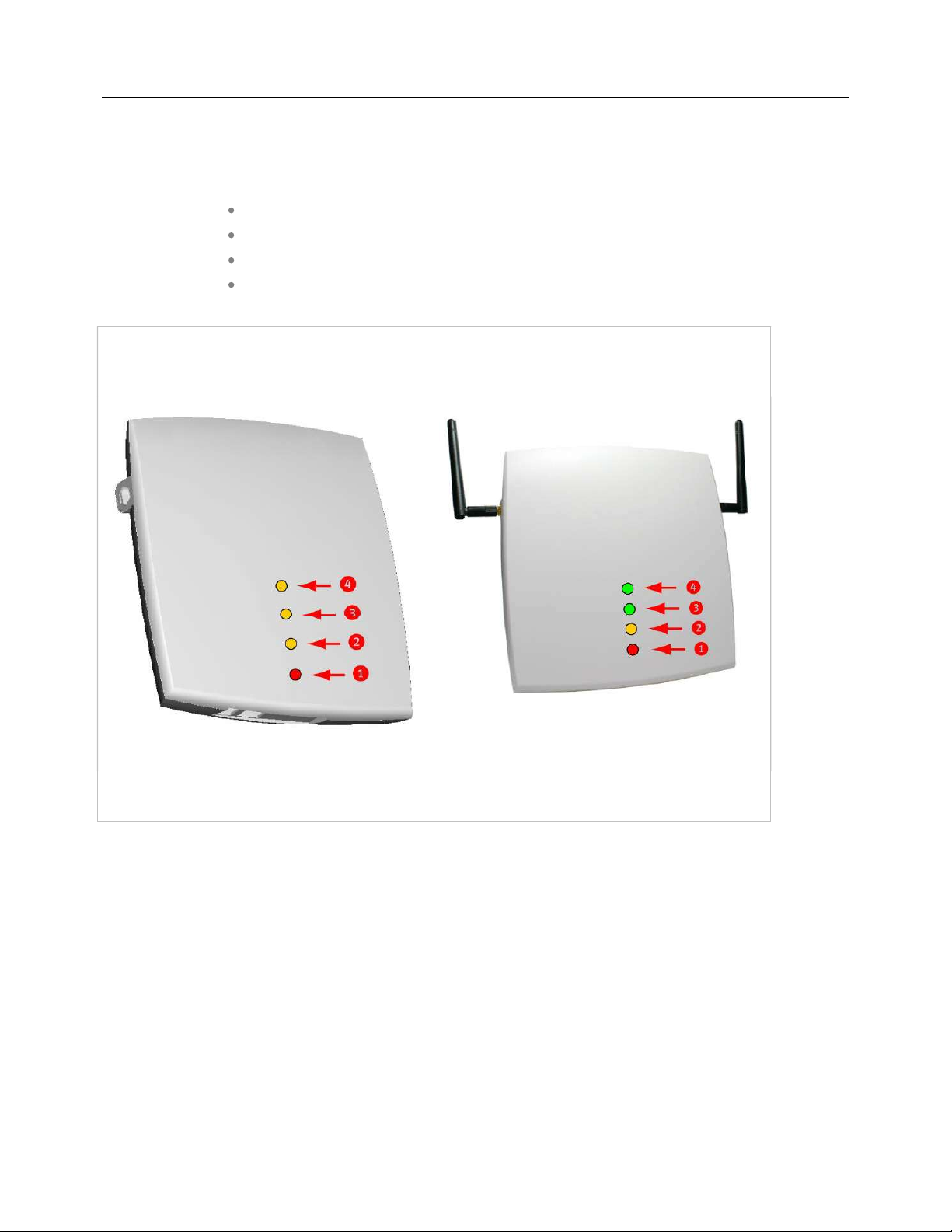
8.5.5 RFP LEDS
8.5.5.13rd Generation RFPs
RFP 35 IP
RFP 36 IP
RFP 37 IP
RFP 43 WLAN
8.5.5.1.1 LED States
RFP 32/34 IP
RFP 32/34 NA
RFP 35/36 IP
RFP 42 WLAN
RFP 43 WLAN
LED 1 Info / Booter; LED 2 System;
LED 3 DECT; LED 4 (unused)
LED 1 Info / Booter; LED 2 System
LED 3 DECT; LED 4 WLAN
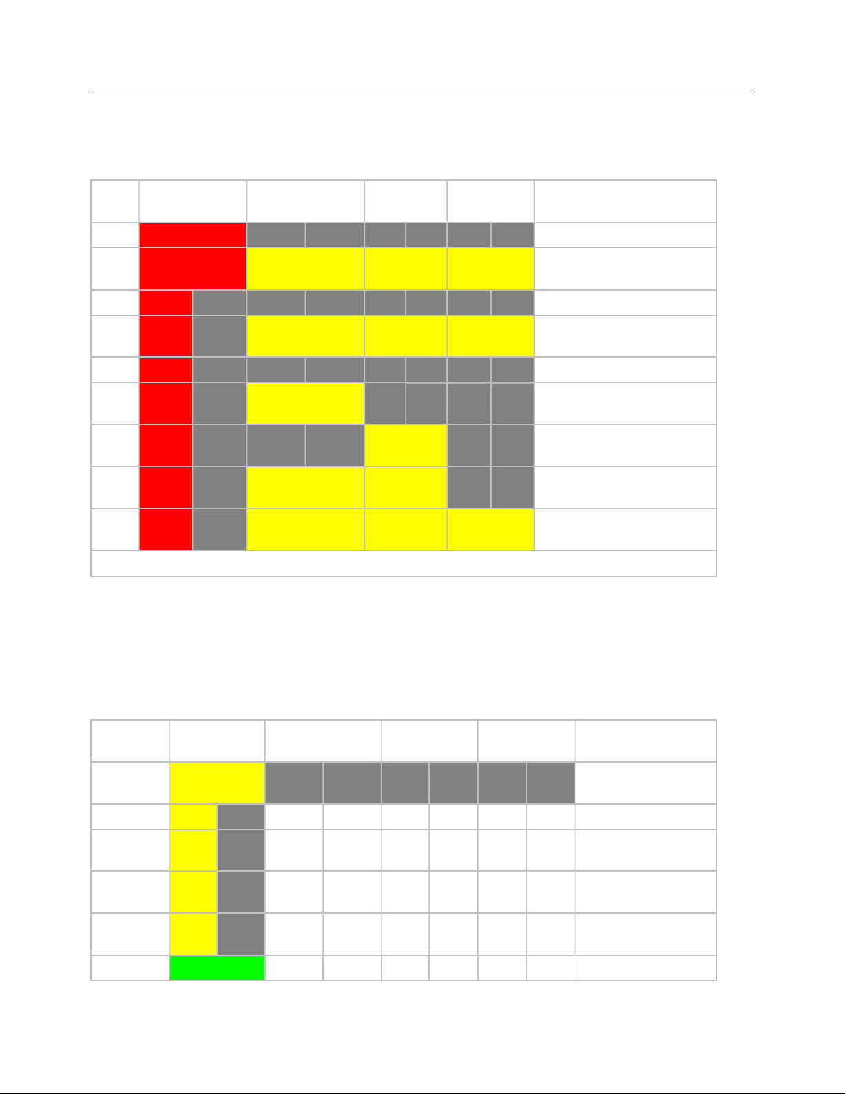
8.5.5.1.2 Booter LED Status
RFP 35/36 IP, RFP 43 WLAN
The RFP 35/36 IP and RFP 43 WLAN booter uses LED1 for signaling its activity. After power up, the
LED 1 (INFO) is red. The successful start of the boot image is signaled by the LED 1 turning orange.
224
Configuration and Administration
TFTP download after DHCP
external configuration
RFP 32/34 IP, RFP 32/34 NA, RFP 42 WLAN
The following table illustrates the different meaning of the LEDs while the booter is active.
LED1 (INFO) LED2 (OMM /
SYSTEM)
LED3
(DECT)
LED4
(WLAN)
Booter cont. Power connected
cont. cont. cont. cont.
Wait for OMM Configurator
Input
1s 1s DHCP
1,9s 0,1s cont. cont. cont.
DHCP failed, wait for OMM
Configurator Input
0,25s 0,25s TFTP download after DHCP
0,25s 0,25s cont.
0,25s 0,25s cont.
0,25s 0,25s cont. cont.
3,9s 0,1s cont. cont. cont.
TFTP download after local
configuration
Multicast
TFTP download after local
configuration and multicast
TFTP failed, wait for OMM
Configurator Input
Now, the kernel / application is running: LED1 will never be RED
8.5.5.1.3 Application LED Status
The following tables illustrate the different meaning of the LEDs while the application is starting or active.
RFP 35/36 IP, RFP 43 WLAN
LED1 (INFO) LED2 (OMM /
LED3 (DECT) LED4 (WLAN)
SYSTEM)
Kernel cont.
kernel boot phase
(inflator, …)
RFPM 1s 1s DHCP phase
1,85s 0,5s
0,5s 0,5s
0,85s 0,15s
DHCP failure (idle
loop)
obtaining external
configuration
failure
cont. Ready
225
SIP-DECT OM System Manual
OMM connect phase
Up & running + OMM
Up & running + OMM
DECT not configured
RFP WLAN
WLAN not configured
LED1 (INFO) LED2 (OMM /
LED3 (DECT) LED4 (WLAN)
SYSTEM)
1,85s 0,15s
RFP
general
1s 1s
1,85s 0,15s
cont.
1,85s 0,15s
1,85s 0,15s
RFP DECT cont.
1,85s 0,15s
cont DECT 'on air'
Up & running + RFP
houses OMM
OMM connection
failure (idle loop)
Up & running (OMM
connected)
warning
failure
on this RFP
DECT inactive (not
synced yet)
Reboot
request
cont. cont. cont. cont. RFP will reboot
8.5.5.24th Generation RFPs
RFP 44
RFP 45
RFP 47 and RFP 47 DRC (Indoor and Outdoor Unit)
RFP 48 WLAN
1,85s 0,15s DECT + call active
1,85s 0,15s
cont.
DECT + call active
+busy bit
on this RFP
1,85s 0,15s WLAN inactive yet
cont. WLAN 'on air'
1,85s 0,15s
cont.
WLAN + assoc.
clients
WLAN failure (e.g.
10 Mbit/s uplink)
See the section 1.2.1.1 RFP 4G DECT Base Station family
226
for more information.

Configuration and Administration
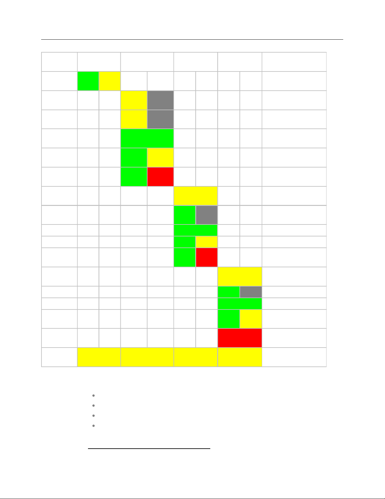
8.5.5.2.1 LED States
The following tables show the LED status of an RFP according to the different states.
A red respectively orange colored field in the table means that the LED glows permanently in red or
orange. A split field with e.g. the specification 1s/1s means that the LED is flashing with a frequency of
one second LED red on and one second LED off. Grey means that the LED is off.
The new RFP family is equipped with one colored LED, which shows the individual states of the 4th
generation RFP.
LED color/rhythm Description
continuous Booter phase
continuous Kernel boot phase
1s 1s Configuration phase
1,9s 0,1s DHCP failure (idle loop)
continuous System up and Running (with or without OMM )
1s 1s OMM connection phase
continuous OMM connected
1s 1s DECT inactive (not synced yet)
continuous DECT “on air”
continuous WLAN “on air”
1s 1s DECT inactive (not synced yet) + WLAN “on air”
continuous DECT + WLAN “on air”
0,1 sec 0,1 sec Button pressed: 0 sec < t < 3 sec = no action
0,1 sec 0,1 sec Button pressed: 3 sec < t < 8 sec = Activate Cloud-Id
0,1 sec 0,1 sec Button pressed: 8 sec < t < 10 sec = no action
0,1 sec 0,1 sec Button pressed: 10 sec < t < 15 sec = Factory Reset
0,1 sec 0,1 sec Button pressed: 15 sec < t < oo = no action
8.5.5.2.2 Turning Off the RFP 4G LED
To turn off the RFP 4G LED,
1. Go to the DECT base stations tab.
2. Select the Advanced settings option and select the Disabled LED check box to disable the LED
for the active DECT and WLAN states.
227

SIP-DECT OM System Manual
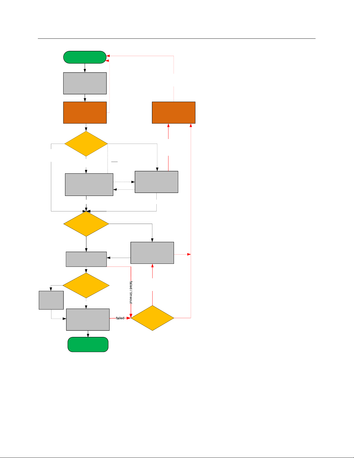
8.6 STATE GRAPH OF THE START-UP PHASES
The following figure illustrates the start-up phase for older 2ndgeneration RFPs. 3rdand 4thgeneration
RFPs use a similar start-up sequence, but they start with the application phase (see below).
228
Power ON
Configuration and Administration
active but
no VLAN
configured
Only one server
is configured
contact this server
wait until
Ethernet link is up
wait 6 seconds for
OMM Configurator
input
No OMM Configurator input
Check for Local
Configuration
active and
VLAN configured
enable
configured
VLAN ID
TFTP Server
list
TFTP Download
send read request
base station reboot
if new configuration
is received by
OMM Configurator
Inactive
If only VLAN
is configured
If DHCP
offer with
VLAN code
received
multiple Servers
are configured
wait 60 seconds for
OMM Configurator
after retry.
DHCP
Offer is validVLAN ID is in use
contact Servers
from List
Timeout or OMM
Configurator
input received
input
no offer
or offer
not ok.
No other
Server
available
yes
IGMP
join group
Server offer
Multicast TFTP
no
TFTP Download
Start
Application Phase
Download failed.
retry other
configured servers
other TFTP
Server
configured
Download failed
only one Server
configured
229
SIP-DECT OM System Manual
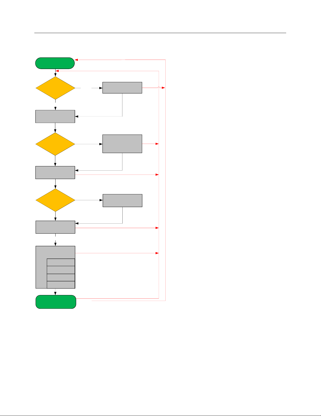
Start Application
Phase
Check for Local
Configuration
active
enable configured
parameter
Check for RFP
config file
not set
Application
init
Check for
OMM IP
connect to OMM
apply config from OMM
inactive
valid offer received
config file server
is set
apply config files
(overwrite local parameter)
this RFP is OMM
RFP application
connect to OMM
DHCP
DHCP no answer
or offer not okay
failed if no valid config
is available on this RFP
download and
apply RFP
config files
failed
start OMM
application
failed
(try 3 minutes)
init configured
applications
up & running
230
syslog
SNMP
DECT
WLAN
failed
Failure e.g. connection to OMM lost
*
any time
major config change of local configuration
 Loading...