

Mitel Networks 80-001224 Users Manual
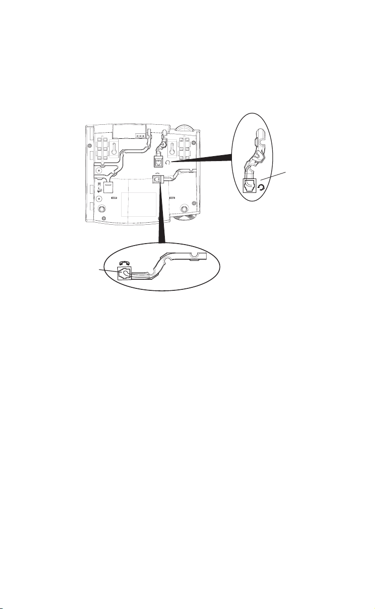
Connecting a Handset or Headset
To Handset
To Headset
Handset
Turn the phone over and locate the handset jack marked j. Insert one
end of handset cord into the jack until it clicks into place. Then route the
handset cord through the groove as shown in the illustration below. Attach
the handset to the other end of the handset cord.
Installation and Setup – 57i CT Base Unit
Headset (Optional)
Turn the phone over and locate the headset jack marked f. Insert the
headset cord into the jack until it clicks into place. Then route the headset
cord through the groove as shown in the above illustration.
Model 57i CT Installation Guide 17
Desk or Wall Installation
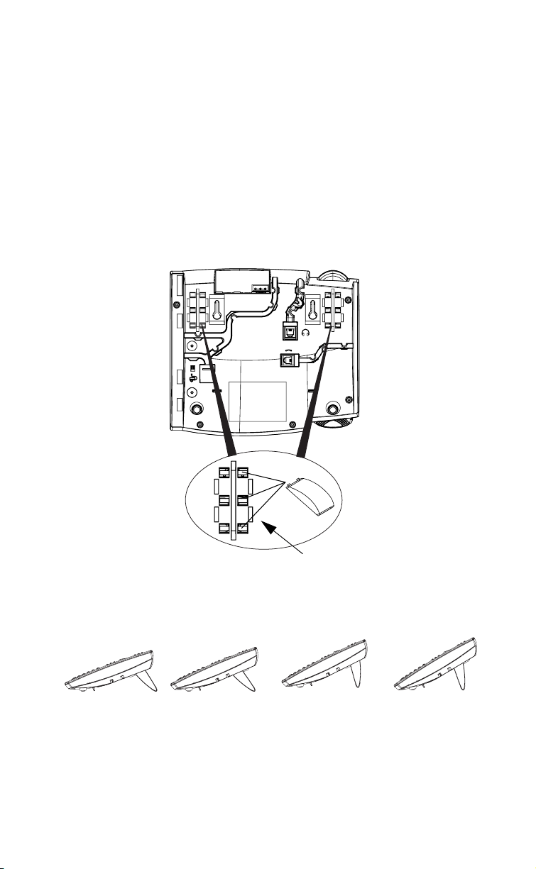
Install on the Desk
The desk installation for the 57i CT IP phone consists of two legs that attach
to the back of the phone near the top corners. A total of four different
viewing angles allows users to personalize their phone viewing preference.
Attach each leg by inserting the tabs on the leg into the slots on the bottom
of the phone. There are three pair of leg slots on each corner of the phone;
each leg uses two pairs (1&2, or 2&3) giving two leg positions designating
different viewing angles. Furthermore, the legs can be reversed which
offer two additional viewing angles.
For a higher viewing angle, use the second and third slots from the top. For
a lower viewing angle, use the first and second slots from the top. Then
push the stand towards the phone until it snaps into place.
Three stand slot locations
for customizing the height
of the desk phone.
Installation and Setup – 57i CT Base Unit
20.7 deg.
Incline Angle
18 Model 57i CT Installation Guide
23.3 deg.
Incline Angle
Total 4 Viewing Angles
26.6 deg.
Incline Angle
30.9 deg.
Incline Angle
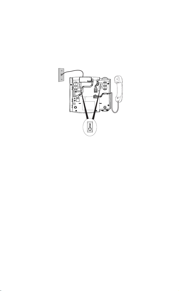
Install on the Wall
The 57i CT IP phone has two pre-drilled wall mounting holes on the back
of the phone. Using the provided wall mount drilling template, locate and
mark the position for the mounting screws on the wall. Depending on the
wall type, you may need to use wall anchors. Both the screws and wall
anchors are included with your phone.
Place the wall mount holes on the phone over the screw heads on the wall
and pull down to lock the phone in.
Wall Mount Holes
Installation and Setup – 57i CT Base Unit
Note: You may wish to purchase a short Ethernet cable from a local supplier for a
wall installation. Also, if 802.3af compliant in-line power is not provided on
your network, and you are installing the 57i or 57i CT base unit on a wall
using a PoE in-line power injector, you may also wish to use an equivalent
flat Ethernet cable rather than the one provided.
Model 57i CT Installation Guide 19
Installation and Setup – 57i CT Cordless Handset
There are two steps involved in setting up the 57i CT cordless handset. The
charging cradle needs to be plugged in and the batteries need to be
installed in the handset.
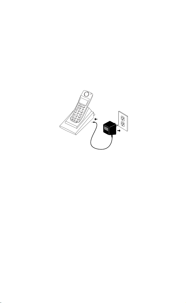
Charging Cradle
The charging cradle is designed to be placed on a desk or any appropriate
flat surface. To set up the charging cradle:
1. Plug the modular cord of the power adapter into the jack on the bottom
of the cradle. Route the cord through the retaining tabs of the molded
cord slot. Verify the cradle rests on all four feet and doesn’t wobble.
2. Plug the other end of the power adapter into a non-switched AC outlet.
It is recommended that the adapter should not be plugged into an electrical power bar and should be the only item plugged into the AC outlet.
Non-switched
AC Outlet
Battery Installation and Charging
The handset is powered by a nickel metal hydride battery pack. To install
and charge the battery:
1. Place the battery pack in the battery compartment with the connector
wires pointing towards the bottom of the handset
2. Connect the battery terminal wire to the charging pins within the battery compartment
3. Slide the cover of the battery compartment from the bottom of the handset until it locks into place
4. Place the handset, face up, in the charging cradle. The handset should
easily slide into the charging cradle. If it does not, check the battery
compartment cover to ensure it is properly closed.
5. Check the battery icon on the handset screen to confirm that it is blinking and that the battery is properly charging.
The cordless handset is automatically "factory paired" to the base station
and will establish contact with the base station once both units have been
successfully installed. This connection can be verified by checking for the
presence of the Reception range icon m beside the battery icon b on the
handset screen.
Installation and Setup – 57i CT Cordless Handset
20 Model 57i CT Installation Guide
 Loading...