

Page 1

SX-2000 Integration Guide
Page 2

NOTICE
The information contained in this document is believed to be accurate in
all respects but is not warranted by Mitel Corporation (MITEL). The
information is subject to change without notice and should not be
construed in any way as a commit ment by MITEL or any of its af fil iat es or
subsidiaries. MITEL and its affiliates and subsidiaries assume no
responsibility for any error or omissions in this document. Revisions of
this document or new editions of it may be issued to incorporate any
such changes.
Nothing in this document may be reproduced in any manner, either
wholly or in part for any use whatsoever, without written permission from
Mitel Corporati on.
Host Command Interface, HCI, MITEL, MiTAI, Nupoint Messenger,
Nupoint Voice, Nupoint Fax, Nupoint Agent, OnePoint Messenger,
SUPERSET, SX-200 and SX-2000 are trademarks of Mitel Corporation.
Windows 95 and Windows NT are trademarks of Microsoft Corporation.
INTEL and Pentium are tr adem arks of Intel Corpor ati on.
All other product names specified in this document are trademarks of
their corresponding owners.
OnePoint Messenger/SX-200 0 Integration Guid e
OnePoint Messenger Releas e 2.0
Part Number 9164-120-116-NA, Issue 2
December 14, 2000
,
, Trademark of MITEL Corporation.
Copyright 2000, MITEL Corporation.
All right s re s e rv e d.
Printed in Canada.
Page 3

Table of Contents
List of Tables...................................................................................viii
1. OnePoint Messenger/SX-2000 Integration Overview ................. 9
What Is OnePoint Messenger and Unified Messaging? ...............................9
Telephony Server....................................................................................................11
Telephony Server Periph era ls.................................... ............................................11
What is PBX Integration?.............................................................................12
Integration Benefits................................................................................................13
Call Processing Overview..............................................................................14
Task Over v i e w..................... .................... .................... ........................... ........15
Message Waiting................... ............................. ..................................... ................16
Integration Strategy ...............................................................................................16
Requir e d S ki l ls..................... .................. ....................... .................. ...............19
How to Use This Guide..................................................................................19
Organization of this Manual..................................................................................20
Other Doc u mentati o n ......... ........ .................... ........................... .................... 2 1
Using Electronic and Printed Versions... .............................................. ................21
Conventions Used in This Guide...........................................................................22
Terms Used for Keys, Commands, and Buttons.................................................... 22
Images and Tables .................................................................................................22
Type Used in Commands and Screen Output........................................................23
List Styles ..............................................................................................................23
Note and Caution Styles ........................... .................... .................... .................... .23
Other Text Styles........ ........... .............................................. .................... ..............23
Contacting Technical Publications...............................................................24
2. Configuring the SX-2000 LIGHT............................................... 25
OnePoint Messenger Requirements of the PBX .........................................25
Dialed Services ........................................................................................................26
User Service s .. ............................. ........................................... .................................26
PBX Programming Overview and Assumptions.........................................27
OnePoint Messenger/SX-2000 Integration Guide,
Issue 2, 12/14/00 iii
Page 4

Directory Number 7999...... ........... .................... .................... ............................. ....29
Forms Checklist ......................................................................................................29
Class of Service Options ................................................................................31
Class of Service for Stations ..................................................................................31
Class of Service for Trunks....................................................................................31
System Options Assignment..........................................................................32
Setting Up the AFC Card Connection .........................................................32
Dimension and Feature Selection................ ............................ .................... ..........32
Cabinet Assignment.................... .............................................. .................... ..........33
System Configuration.............................................................................................33
Digital Link Descriptor Assi gnment.................................... .................... .............34
Digital Link Assignment ............................... ............................. .................... ........36
Trunk Programming....................... .. .... .... .. .... .... .. .... .... .. .... .... . .. .. .... .... .. .... ...36
MSDN/DPNSS/DASSII Trunk Circuit Descriptor Assignment............... ..........36
Trunk Service Assignment..................................... .................... ............................37
Trunk Assignment.................. .................... ............................. ...............................37
Assigning Trunk Groups to the Message Center.................................................38
Creating Directory Number 7999 .........................................................................39
Programming Voice Mail Ports....................................................................39
Assigning a Hunt Group to the Message Center ........................... ......................39
System Speed Call Assignment........... .............................................. .................... .40
Call R ero ute As sig n ment ........ .. ........................................... ..................................4 1
Call Reroute Always Alternative Assignment...................................................... 41
Automatic Route Selection (ARS) Assignment............................ ........................42
Route Assignment....................... ..................................... ............................. ..........42
Class of Restriction (COR) Group Assignment.................... ...............................43
Programming the Automated Attendant (Receptionist)............................43
Programming Fax on Demand .....................................................................44
3. Installing Line Cards in the Telephony Server..........................45
What Hardware Do You Need on the Telephony Server?.........................45
Fiber Optic Cable Specifications...........................................................................46
Preparing the Installation Site......................................................................47
Accommodating the TS-800 Telephony Server Tower.......................................47
Setting Up MVIP Arrays...............................................................................48
iv
Table of Contents
Page 5

Setting MVIP Termination . ...................................................................................48
Connecting Cards through an MVIP Cable .......................... .................... ..........49
Setting Interrupts and Base Addresses........................................................49
Installing Brooktrout Fax Cards......................................... .... ...... .... ...... .... .51
Installing and Configuring an NMS Card................................ .... ...... .... .....52
Creating the AG Configuration File.....................................................................53
Running the NMS AG Configurator Program....................................................53
Using Notepad to Edit AG.cfg ...............................................................................56
Enabling the Mitel AFC Card with MiTAI.................................................57
Installing the AFC Card ........................................................................................57
Configuring the NMS and CTI Software.............................................................58
Making and Verifying Connections .............................................................59
Verifying Fiber Link Synchronization between the AFC and PBX..................59
4. Installing Mitel Telephon y Application Interfa ce (MiTA I) . .... 61
What You Need to Complete this Chapter..................................................61
MiTAI Installation.........................................................................................61
Installing MiTAI on the Telephony Server ..........................................................61
Editing the Server Hosts File.................................................................................65
Checking the Operation of the MiTAI Link to the PBX............................65
Where Now?.................... .... ...... .... ...... .... ...... .... ...... .... ........... .... ...... .... ...... ....66
5. Configuring OnePoint Messenger PBX Integration Software.67
Integrating the Telephony Server with the SX-2000 PBX.........................67
Show N Tel Setup Procedures ...............................................................................68
Configuring Show N Tel with a PBX ...........................................................68
Editing the SNT Parameters Tab.................................................................71
Assigning Programs to Lines ........................................................................72
Configuring and Testing the Notification Server................................................74
Using the SNT Manager Runtime Tab to Assign Telephony Applications.......76
Setting Telephone User Interface Parameters ............................................78
Editing the Telsrvr.ini File. .. .................... .............................................. ................80
Testing Te l ephony Ser v er S ta rt and Stop... ..................... .......................... ..80
Configuring OnePoint Messenger to Auto-start .........................................81
Running the Telephony Applications...........................................................81
OnePoint Messenger/SX-2000 Integration Guide,
Issue 2, 12/14/00 v
Page 6

Reassigning Lines to Other Applicat ions ............... .................... .................... ......82
6. Troubleshooting the Integration.................................................85
System Validation Tests ...............................................................................85
Running Validation Tests ......................................................................................85
Testing the Network Connection...........................................................................86
A. PBX Integration Worksheet.......................................................87
Workflow Overview.......................................................................................87
PBX Integration Worksheet Fields.......................................................................88
Numbering Ports.....................................................................................................89
Creating Hunt Groups ...........................................................................................89
PBX Integration W orksheet (Sample of a completed worksheet)........................90
PBX Integration Worksheet.....................................................................................91
Index .................................................................................................93
vi
Table of Contents
Page 7

List of Figures
Figure 1-1 Network Diagram ..................................................................................... 10
Figure 1-2 Hunt Group Mapping to Telephony Server Ports ....................................18
Figure 2-1 Trunk and Extension Topology ................................................................28
Figure 3-1 Windows NT Diagnostics, Resources Tab, IRQ List ...............................50
Figure 3-2 NMS AG Configurator Main Screen ...................................... ..... ....... .......54
Figure 3-3 NMS Board Configuration Screen ............................................................ 55
Figure 3-4 AFC Card .................................................................................................58
Figure 4-1 MiTAI Settings Dialog, Hardware Tab .....................................................63
Figure 4-2 MiT AI Se ttings Dialog , So ftware Tab ........ ....... .............. ............... ...........64
Figure 5-1 Show N Tel Manager, Switch/CTI Tab .....................................................69
Figure 5-2 Show N Tel Manager, Configure CTI, Device Map Tab .................... ..... ..70
Figure 5-3 Show N Tel Manager, Parameters Tab .................................................71
Figure 5-4 Show N Tel Manager, Runtime Tab .........................................................77
Figure 5-5 Show N Tel Runtime Tab, Assign Phone System ....................................78
Figure 5-6 Show N Tel Mgr, Operate and Monitor Show N Tel Window . ..................83
OnePoint Messenger/SX-2000 Integration Guide,
Issue 2, 12/14/00 vii
Page 8

List of Tables
Table 2-1 PBX Trunks Mapped to SNT Lines and Applications............................... 28
Table 2-2 SX-2000 Forms Checklist ...................................................................... 30
Table 2-3 Class of Service Options Assignment, COS 10....................................... 31
Table 2-4 Class of Service Options Assignment, COS 21....................................... 31
Table 2-5 System Options Assignment.................................................................... 32
Table 2-6 Dimension and Feature Selection .......................................................... 32
Table 2-7 Cabinet Assignment ............................................................................... 33
Table 2-8 System Configuration ............................................................................. 34
Table 2-9 Link Descriptor Assignment .................................................................... 35
Table 2-10 Digital Link Assignment ............................................................................ 36
Table 2-11 MSDN-DPNSS-DASSII Trunk Circuit Descriptor Assignment ................ 36
Table 2-12 Trunk Service Assignment....................................................................... 37
Table 2-13 Trunk Assignment .................................................................................. 38
Table 2-14 Trunk Group Assignment ........................................................................ 39
Table 2-16 System Speed Call Assignment............................................................... 40
Table 2-15 Hunt Group Assignment........................................................................... 40
Table 2-17 Call Rerouting Assignment....................................................................... 41
Table 2-18 Call Rerouting Always Alternative Assignment........................................ 41
Table 2-19 Automatic Route Selection Assignment................................................... 42
Table 2-20 Route Assignment.................................................................................... 42
Table 2-21 Class of Restriction Group Assignment ................................................... 43
Table 2-22 Trunk Group Assignment for Automated Attendant .................... ............ 43
Table 2-23 Trunk Group Assignment for Fax on Demand ......................................... 44
Table 5-1 Telephony Applications............................................................................ 75
viii
Table of Contents
Page 9

1. OnePoint Messenger/SX-2000
Integration Overview
This chapter provide s an overview of the components, tasks, and benefits of the integration between the Mitel SX-2000™ PBX and the
OnePoint Messenger™ Telephony Server to create a unified messaging environment. It includes details on configuring the PBX to support Telephony Server functions, installing the line cards in th e
Telephony Server, and configuring integration software on the Telephony Server, including setting up telephony applications.
This chapter also provides information about the organization and
styles used i n this book, and about other related documentation. This
chapter contains the fo llowing sections:
Section Page
What Is OnePoint Messenger and Unified Messaging? 9
What is PBX Integration? 12
Call Processing Overview 14
Task Overview 15
Required Skills 19
How to Use This Guide 19
Other Documentation 21
Contacting Technical Publications 24
What Is OnePoint Messenger and Unified Messaging?
OnePoint Messenger is a software suite that, when combined with
other hardware and software products, provides a unified messaging
environment. Unified messaging is the combination of telephone
messages, fax, and e-mail on one mail server. The OnePoint
OnePoint Messenger/SX-2000 Integration Guide
, Issue 2, 12/14/00 9
Page 10
Messeng er se rver s o ftw are i s instal led on two Microsoft Windows
NT Server 4.0 systems:
• The OnePoint Messenger Exchange Extension is installed on the
computer running Micr osoft Exchange
(“the Exchange Server”)
to support unified messaging on Exchange.
• A large suite of softwar e components providing messaging and
maintenance services are installed on the Telephony Server,
which handles communicati on betwee n the telephony network
and Microsoft Exchange.
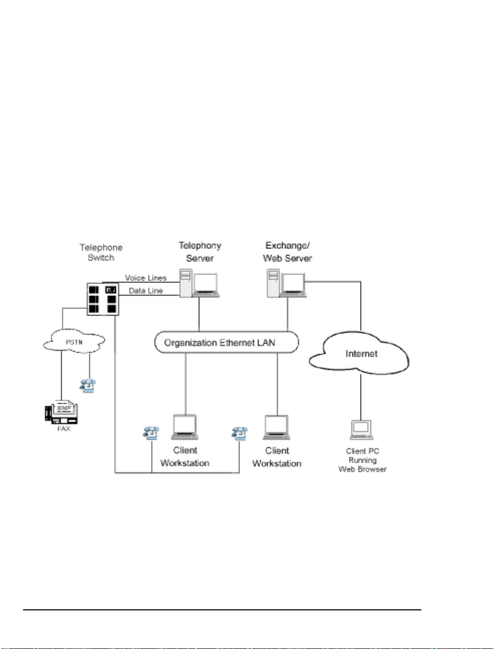
The network diagra m in Figure 1-1 shows the major components that
provide the unified messa ging service, examples of the clients, and
the relationship between the components.
Figure 1-1 Network Diagram
See Chapter 1 in the OnePoint Messenger Administrator Guide for a
detailed system overvie w, a summary of each of the hardware and
software components, and an overview list of tasks. Chapter 1 in the
OnePoint Messenger User Guide also has a basic system overview
and a summary of what you can do with OnePoint Messenger.
10 Chapter 1, OnePoint Messenger/SX-2000 Integra tion Overview
Page 11

Telephony Server
In these guides, “Telephony Server” is used to refer to the collection
of OnePoint Messenger telephony applications that reside on “the
Telephony Server” (the computer), while “the Telephony Server”
refers to the computer running the Windows NT Server 4.0 operating
system. The backplane of the Telephony Server contains the telephony “line cards” that provide the connection to the PBX. To provide the ability to edit syst em gree tings and the T e xt-to-Speech
dictionary, you can add a multimedia setup to the Telephony Server,
but, administrators typically use a separate system on the LAN for
multimedia editing.
The OnePoint Messenger software on the Telephony Server is comprised of a group of Wi ndows NT Server applications that, among
other tasks, provide the information conduit between the PBX and
Microsoft Exchange. Those telephone call routing and messaging
services include:
• Controlling what happens to calls that are not answered and providing the caller the ability to leave and retrieve voice messages
• Providing digitization and compression of telephone messages
for storage on Exchange or forwarding to VPIM accounts, and
also reverse transcoding of messages saved on Exchange back to
callers and VPIM accounts
• Enabling OnePoint Messenger subscribers (“users”) to retrieve
and reply to e-mail messages that are read to them using the textto-speech (TTS) capabilities of Telephony Server
• Providing advanced fax handling features, including routing email to fax machi nes an d a Fax on Demand se rvice; see Chapte r 4
of the OnePoint Mess eng er Administrator Guide for a discussion
of OnePoint Messenger fax features.
Also included on the Telephony Server is a group of OnePoint Messenger suppor t programs. F or an overview on them and rela ted tasks,
see Chapter 1 in the OnePoint Me ssenger Admi nistr ator Gui de. Then
see Chapter 5 in that guide for operational details.
Telephony Server Peripherals
Cards: The Telephony Server requires a network interface card to
communicate with the Exchange Server and with user computers that
request Call-Me sessions. To provide the PBX interface, the Telephony Server requires at lea st one line card that provides call control
What Is OnePoint Messenger and Unified Messaging? 11
Page 12

and voice processing resources. Those services can be provided by
several possible combinations of analog line cards from Mitel and
Natural MicroSystems (NMS) connecting to a FIM card on the SX-
2000. Use an ISA- bus Br ooktrout fax card connected to th e othe r line
cards through an MVIP cabl e to provide fax resource s. Details on t he
supported cards appear in Chapte r 3 (page 45). Appendix B in the
OnePoint Messenge r Installation Guide also provides line card installation notes. See also the manufactur ers’ documentation.
Modem: To provide remote technic a l support, connect a modem to
the Telephony Server and to an out side telephone line, then configure
the program pcAnywhere, which is included on the OnePoint Messenger CD- ROM, to commun icat e ov er tha t mod em .
What is PBX Integration?
Providing complete PBX integration to the Telephony Server means
that you dedicate at least one extension in a hunt group on the PBX to
the Telephony Server Message Center, another for the Automated
Attendant, and another for the Fax on Demand service , r oute
OnePoint Messenger subscribe r extensions to the OnePoint Messenger Telephony Server for voice mail with Message Waiting services
enabled, set up software on the Telephony Server that can interpret
calling line information (CLI) sent by the PBX, and set up the Message Center to use that CLI to respond appropriately to the caller.
T ypically, CLI includes the caller’s phone number (and name if
Caller ID is set up), the called part y’s (OnePoint Messenger user/subscriber) extension, and the reason why the caller has been routed to
the Message Center. Those reasons include:
• The OnePoint Messeng er user ( subscr iber) do es not answe r his or
her phone.
• The OnePoint Messenger user’s phone is already in use when the
call arrives.
• The OnePoint Messenger user sets up a request to the PBX that
incoming calls be automatically routed to voice mail.
• The OnePoint Messenger user receives the call and transfers it to
voice mail, for example, so the c aller can leave a fax in the user’s
mailbox.
• A OnePoint Messenger user calls the Message Center directly to
retrieve messages.
12 Chapter 1, OnePoint Messenger/SX-2000 Integra tion Overview
Page 13

The Message Center uses CLI to associate the called telephone number with a particular mailbox, retrieve the appropriate user’s greeting
from that mailbox, play it to the caller, then either commence a mailbox login sequence or a message recording sequence.
For example, the most common kind of call routed to the Message
Center is typically from a caller r outed to a mailbox when the associated telephone is not answered. The Message Center would play the
user’s gr eeting created for that condition. Consider Joe User. He has
recorded a general greeting for that condition:
“This is the mailbox of Joe User. I’m sorry he was too
lazy to pick up the phone, but, if you wait for the
beep after this long-winded greeting finishes, you can
record a message for him that I’ll be happy to play
when he calls in to retrieve his messages.”
If the inte gration software fails to detect the CLI, the Message Center
does not know why the caller has been routed there or for what mailbox the call is intended, so the Message Center answers generically:
“Welc ome to the Me ssage Cente r. Please en ter a mailb ox
number.”
Integration Benefits
The integration between the PBX and the Telephony Server provides
these benefits:
• Forward to Pers o nal Greet in g : Provides the ability to play a
user’s personal greeting to a caller who has been forwarded to
voice mail.
• Auto Logon: The Telephony Server can rec ognize a caller as a
OnePoint Messenger subsc riber (“user”) , rather than as a n outside
caller , when calling directly from the user’s phone. The Telephony Server greets users by name and asks for their passcodes.
• Multiple Use Ports: Allows use of the same port for dynamic
allocation of ports fo r the Automate d Attendant, the Message
Center , including Text-to-Sp eech e-mail access, or fax services.
• Direct Answer to Internal Message: Allows a message recipient
to record an answer to a message from another user witho ut having to first dial the user’s extension.
• Message Notification: Allo ws the Telephony Server to send a
message waiting notifi cation to a user through the PBX. The
What is PBX Integr a tion? 13
Page 14

PBX then activates the message wait ing indicator, such as a light
or a stutter dial tone, on the user’s extension.
Call Processing Overview
This is a basic overview of the processing sequence of calls routed
from the SX-2000 PBX to the Telephony Server:
1. The PBX receives a call intended for an extension managed by
the PBX.
2. If the call is to a OnePoint Messenger user whose phone is busy
or is not answered, the PBX redirects the call to the T elephony
Server. The PBX also routes calls to the Telephony Server that
are forwarded by user s to their voice mail accounts, or users who
make a direct call to the Message Center (the mailb ox access
pilot number) on the Telephony Server.
3. Other Telephony Server services can be associated with particular phone number s, such as the Automated Attendant and the Fax
on Demand service. For details on those services, see Chapter 3
in the One Point Messenger Administrator Guide.
4. The call arrives at the Telephony Server in two streams of data—
the voice from the call itsel f and info rmat ion about the call,
including the caller’s phone number, the called party’s phone
number, and the reason code why the call was sent to the Telephony Server; this calling information is known as CLI—calling
line identification.
The two streams go to a port on a line c ard. Then, if you install a
Mitel AFC card, the AF C routes the c all stream to a DSP resource
card (NMS AG-0 or AG-24 for voice; Brooktrout fax card for
fax) while processing the CLI and managing th e call. If you only
install one or more NMS AG-8s, both streams stay on the AG-8.
5. The line card detects the cal l and p as ses the CL I dat a to Telephony Server so ftw are t ha t uses the call ed num b er to det erm i ne
whether to play a system greeting or a user’s greeting.
6. T elephony Server plays the appro priate greeting. The NMS card
converts it to analog and the AFC card plays it to the caller .
7. The Telephone User Interface (TUI) on the Telephony Ser ver
sends the appropriate digitized prompts to the NMS card for conversion and playing to the calle r. For example, if the call is for a
user , the TUI prompts the caller with the messaging options
14 Chapter 1, OnePoint Messenger/SX-2000 Integra tion Overview
Page 15

Task Overview
available, such as to record or re-record a voice message, or to
leave a fax.
8. The caller responds with a voice message or keypad input.
9. The NMS card converts the analog input from the caller ( the
voice message and keyed response s to prompts) into digital
strings for Telephony Server.
10. Telephony Server packages the c a ller’s messa ge into a digital file
and routes it to the recipient’s mailbox on the Exchange Server
and sends an MWI to the user through the PBX.
Reciprocally, when users retrieve voice messages from a telephone,
the NMS card converts the stored digitized voice messages back into
analog voice for delivery to the user.
The following is a brief sequence of the groups of tasks required to
integrate OnePoint Messenger and the Mitel SX-2000.
1. Complete the PBX Integration Worksheet that appears at the end
of Appendix A (see “PBX Integration Worksheet” on page 91).
2. Install Fi ber In t erfa ce M odule (FIM) carrier and daughter digital
line cards in the SX-2000 PBX, then configur e the PBX to support the Telephony Server fu nctions. See Chapter 2 (page 25).
3. Install the line card(s) on the Telephony Server. Use NMS AG-8
DSP (AG-0) cards and/or AG-24 cards with the Mitel AFC card,
and (optionally) a Brooktrout fax card. See Chapter 3 (page 45).
4. Install Microsof t soft ware on the Telephony Server. See
Chapter 4 in the OnePoint Messenger Installation Guide.
5. Install and configure the Mitel MiTAI 7.5.3 software on the Telephony Serv er. See Chapter 4 (pa g e 61).
6. Install OnePoint Messenger on the Telephony Server. Microsoft,
Show N Te l, Brooktr out fax, NMS and other vendor s’ software is
installed with OnePoin t Messenger. See Chapters 1 through 3 in
the OnePoint Messenger Insta llation Guide.
7. Configure the line card( s) on the Telephony Server. See
Chapter 3 (page 45).
8. Configure Show N Tel and the other telephony settings in
OnePoint Messenger. See Chapter 5 (page 67).
Task Overview 15
Page 16

Message Waiting
The procedures in Chapter 5 for step 7 above include setting up the
Notifications ap plication in Show N Tel to provide message waiting
indications. The OnePoint Messenger Administrator Guide has a
procedure in Chapter 2 for enabling message notification by paging
for individual users and a general section in Chapter 3 on message
waiting notification.
Integration Strategy
OnePoint Messenger provid es three services that callers can access
directly by dialing unique pilot numbers. They are Automated Atten-
dant (automated receptionist), Message Center (subscriber access to
their own mailbo xes), and Fax on Demand (faxback). It is also possible to access the Automat ed Att endant from the Message Center, and
Fax on Demand from the Automated Attendant, so, if resources are
limited, you do not need to dedicate pilot numbers to them.
There are several ways to allocate resources to each service:
• On the PBX:
• Create an extension that callers can dial to reach the service.
• Create a hunt group for the service . A larger hunt group provides more access to the service. You can also overlap hunt
groups. What hunt groups are overlapped inf luences how
available those double -duty lines are.
• In OnePoint Messenger:
• You can assign the general purpose Telephony Server te le ph-
ony application to a line, which will support each of the three
services, and provide the desired service based upon the
dialed extension.
Or
• T o provide dedicated access to Automate d Attendant, you
can assign the AutoRecep telephony application to one or
more lines. To provide dedicated access to Fax on Demand,
you can assign the FaxonDemand telephony application to
one or more lines.
Or
• If there is no pilot (extension) dedicated to Automated Attendant, you would not assign the AutoRecep telephony applica-
16 Chapter 1, OnePoint Messenger/SX-2000 Integra tion Overview
Page 17

tion. If there is no pilot (extension) dedicated to Fax on
Demand, you would not assign the FaxonDemand.
For example, to ensure connectivity for messaging while still providing some direct dial access to Automated Receptionist and Fax on
Demand, you could create one hunt group, with its pilot assigned to
the Message Center, then assign single published phone extensions
within the hunt group to Automated Receptionist and/or Fax on
Demand, each set up with all calls forwarded to voice mail.
If you do set up hunt groups for all three services, of course the number of lines in those hunt groups af fects availability. How the hunt
groups are mapped to Telephony Server lines also influences how
available ser vices are . Hunt gr oups can overla p, so a line t hat a ppears
in two or more hunt groups is more likely to be busy than a line
appearing in only one of those groups.
For example, consider the Fax on Demand service. If the Fax on
Demand hunt group is simply a subset of the Messaging hunt group,
someone calling the Fax on Demand service may not get through
immediately if all lines are in use servicing callers accessing mailboxes. To ensure that callers to the Fax on Demand se rvice get bette r
access to it, you can create a hunt group for the service that does not
use lines included in other hunt groups.
The other half of the provisioning decision process is the assignment
of telephony applicat ions to the available Telephony Server ports. A
port that is assigned to a dedica ted application, such as Fax on
Demand, is not available to call ers seeking a different application. If
the line from the PBX that is mapped to that port is only in a hunt
group for a different application, a caller route d to that line through
the hunt group will not get the desired service.
One way to avoid such conflicts is to assign the “Telephony Server”
application to all inbound por ts, because it is a general purpose application that provides the three dialed services (Automated Attenda nt,
Message Center/mailb oxes, Fax on Demand). However, using that
simplistic stra tegy might result in events such as important sales literature on your Fax on Demand se rvice not being ac cessible if all ports
are busy with users’ calls to their mailboxes.
The diagram in Figure 1-2 shows an example of PBX hunt groups
mapped to Telephony Server ports an d thei r associated telephony
applications. The assignme nt of applic ations is not the rec ommended
allocation of applic at ions. It is a simplified assignment whose purpose is to illustrate the assoc iation of applications with hunt groups.
Task Overview 17
Page 18
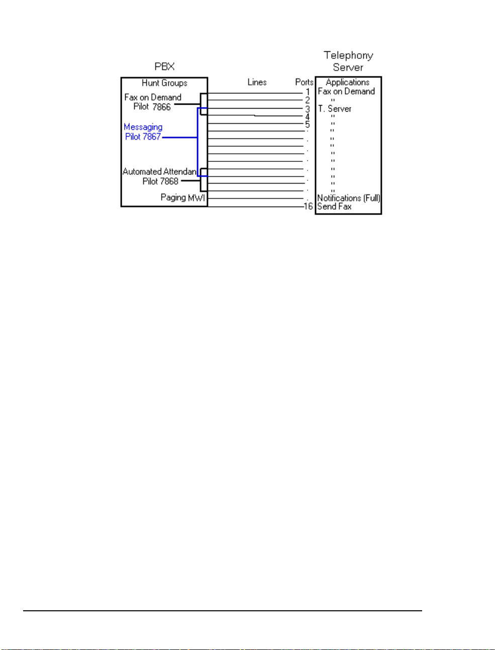
Figure 1-2 Hunt Group Mapping to Telephony Server Ports
Figure 1-2 shows three overla pping hunt groups. Ports 3 and 4 take
calls from both the Fax on Demand hunt group and the Messaging
hunt group. Ports 11 and 12 take calls from both the Messaging hunt
group and the Automated Attendant hunt group.
The Fax on Demand hunt group has four lines. Two of those lines
connect to ports 1 and 2, which are assigned the Fax on Demand
application. Any call er reaching t hose two por ts is greet ed by the Fax
on Demand service greeting. On the other hand, because ports 3 and
4 are connected to li nes tha t are in t wo hunt group s, Telephony Server
must interpret the CLI data to det ermine which hunt group has called
to determine which greeting to play. If T elephony Server determine s
that the called number is the Fax on Demand pilot, it ru ns the Fax on
Demand application, and so fort h.
In the example, Automated Attendant operation is similar to Fax on
Demand, with its hunt group overlapping the numbers in the Messaging hunt group.
Notifications a nd SendFax are outbound applications that require outdial ports on the PBX. Their lines are not included in the lines monitored by the call pickup box.
The discussion on programming the PBX in Chapter 2 contains a n
example of creating trunk groups to support dedicated access to the
Automated Attendant and Fax on Demand, in addition to supporting
those services through trunks tha t provide access to the Message C enter . Ta ble 2-1 (page 28) shows a sample assignment of telephony
applications on the Telephony Server. Table 2-12 (page 37) shows a
trunk group set up to provide trunks for the first five lines and the
associated Telephony Server telephony application in Table 2-1.
18 Chapter 1, OnePoint Messenger/SX-2000 Integra tion Overview
Page 19

Required Skills
T able 2-22 (page 43) shows an alternative setup with Trunk 103 dedicated to the Automated Attendant, while Table 2-23 (page 44) shows
Trunk 104 dedicated to Fax on Demand. Both of those services can
also be provided by the Telephony Server application, depending on
how OnePoint Messenger is set up, so your PBX technician needs to
coordinate with the OnePoint Messenger installer to assure that the
trunk allocation s on the PBX match the Telephony Server setup and
the preferences of your organization.
While OnePoint Messenger is designe d to be rel atively simple to
implement and use, and the OnePoint Messenger guides detail the
Windows NT and Exchange tasks needed to configure and manage a
OnePoint Messenger environm ent, installers and administ r ators
should not rely solely on this documentation. Integrating the
OnePoint Messenger Telephony Server with a Mi tel PBX re quire s the
skills of a Mitel-certified PBX technician and certification in the
installation of OnePoint Messenger. Before entering training,
OnePoint Messenger insta llers are expected to have Microsoft Certified Systems Engineer (MCSE) cert if ication in Win dows NT Server
4.0 and Microsoft Exchange.
If you wish to provide user access to mailboxes using a Web browser,
you must install and manage Microsoft’s Internet Information Server
(IIS), which requires training equivalent to completion of the IIS
course in the MCSE course series.
When installing and managing Windows NT and Exchange, you are
required t o perform NT administrator functions—setting u p domains,
creating administ rator accounts, and performing software maintenance and backups. OnePoint Messenger applic ations use standard
Windows interfaces and intero perat e w ith N T system utilities.
How to Use This Guide
This guide contains tasks for integrating a Mitel SX-2000 PBX with
the OnePoint Messenger Telephony Server, including setti ng up hardware and software on the Telephony Server and configuring the PBX
to communicate with the Telephony Server. Use this guide in conjunction with the OnePoint Messenger Installation Guide (for
OnePoint Messenger version 2), using this guide to replace Chapter 4
in that guide. The section “Task Overview” above lists the sequence
of installation and integration tasks with the associated chapters.
Required Skills 19
Page 20

This manual lists t he criti cal P BX featur es that mus t be en abled, but it
does not detail the use of the PBX user interface. Also, this manual
does not discuss the comple te array of monitoring, programming, and
troubleshooting options available to the installers and administrators
of the Mitel PBX and of OnePoint Messenger. Becoming familiar
with those options requires classroom training offered for both of
those products.
For installing cards in the Telephony Server, refer to Chapter 3 as a
summary, but to be sure you have all current information and details
on options, see the manufacturers’ documentation, as listed in
Appendix A of the OnePoint Messenger Installation Guide.
Sources of information on other supporting hardware and software
are listed below in “Other Documentation ”.
Organization of this Manual
This manual contains six chapters, an appendix, and an index:
• Chapter 1 introduces you to OnePoint Messenger and its documentation.
®
• Chapter 2 (page 2 5) explains how to config ure the SX-2000
LIGHT PBX to recognize the OnePoint Messenger Telephony
Server.
• Chapter 3 (page 4 5) lists the hardwa re necessary to install on the
Telephony Server to integrate with the SX-2000, and it summarizes the installa tion process.
• Chapter 4 (page 6 1) covers the installation of Mitel’s
MiTAI 7.5.3 software on the Telephony S erve r.
• Chapter 5 (page 6 7) explains how to config ure the OnePoint
Messenger software on the Telephony Server that supports the
PBX integration and telephony applications, such as Message
Waiting, paging notification, and fax servic es.
• Chapter 6 (page 8 5) provides trouble shooting advice, including
system validation tests. For more, see the OnePoint Messenger
Installation Guide and the OnePoint Messenger Administrator
Guide.
• Appendix A (page 87) provides a PBX Integration Worksheet,
with explanation, for planning and recording pilot numbers, associated hunt groups, and telephony application line assignm ents.
20 Chapter 1, OnePoint Messenger/SX-2000 Integra tion Overview
Page 21

Other Documentation
The OnePoint Messenger documentation set includes:
• OnePoint Messenger Administrator Guide
• OnePoint Messenger Getting Started Guide
• OnePoint Messenger Installation Guide
• OnePoint Messenger User Guide
• OnePoint Messenger Quick Reference Card for the telephone
• Integration guides for PBXs: Fujit su 9600, Lucent Definity , Mite l
SX-200 and SX-2000, NEC 2400, and Nortel Meridian
The OnePoint Messenger Administrator Guide contains a system
overview and administra tion details that can help you, the inst aller,
understand the purposes and use of the components. It contains procedures for creating user mailboxes (Chapter 2), configuring the Telephony User Interface (Chapter 3), managing fax services (Chapter 4),
and operating and maintaining the Telephony Server (Chapter 5), as
well as details on each OnePoint Messenger utility.
The OnePoint Messenger User Guide describes the use of OnePoint
Messenger features —on Outlook , a Web browser, and the telephone—including the many fax features.
Other useful documentation includes Wi ndows NT and Exchange
manuals, as well as manuals covering the other Micr osoft software
that supports OnePoint Messenger. Contact information for
Microsoft and for other vendors whose products complete your
OnePoint Messenger unified messaging environment appears in
Appendix B of the OnePoint Messenger Administrator Guide.
Using Electronic and Printed Versions
This guide use s a form at that acco m modates both o n-s cree n viewing
and printing. The text is aligned to 7" by 9" borders, so tha t, when
printed on normal letter stock , the re is a lot of room for you to make
notes. Use Acrobat Reader version 3.0 or better to view and print
PDF versions of the document.
Electronic lin ks: Blue text indicates hyperlinks, as exemplified by
the blue links in this chapter, including the table at the beginning of
each chapter containing e le ctronic links to the major topic headings.
Other links t hat appear in the electronic Ac rob at version are the bookmark list and thumbnail page image views displayed by Acrobat.
Other Documentation 21
Page 22

Conventions Used in This Guide
Formatting convent ions used in OnePoi nt Messenge r guides give you
extra cues about the action that you are to take.
Terms Used for Keys, Commands, and Buttons
The commands “select” , “ c lear”, “click”, and “choose” all mean basically the same thing—to make a choice—but the terms are used in
specific situations:
• “Choose” is used in menus, such as the Windows Star t menu and
program menus, to indicate menu items.
• “Click” is used for obvious buttons, up and down arrows, in edit
boxes, spin controls, and for the Windows Start button.
• “Double-click” is used in a ny situation where pressing the mouse
button twice is the most appropriate action, although other
options may be available.
• “Press” is used when indicating a compute r keyboard or telephone keypad key. There are brackets around the keyboard key,
as in “Press [Tab].”
• “Select” is used on property pages (tabs) and dialogs, such as to
indicate items in a field or group of options. “Clear” is used to
deselect a check in a check box or an entry in a field.
This guide generally does not include the keyboard shortcuts for
menus and commands. To use the keyboard shortcuts, you should:
• Display menus by pr essing [Alt] a nd the underlined character displayed on the screen (for example, pr ess [Alt+F] for the File
menu).
• Choose commands by typing the underlined character displayed
on the screen (for ex am p le, p ress [S] fo r the Sa v e command).
An instruction that involve s making a choice from a menu is structured: “From the XXX menu, choose YYY”. This style is also used
for dialog boxes. As you become familiar with the style , you can
focus on the words in bold as the critical operative phrases.
Images and Tables
Tables and inline graphics in this guide contain captions with numbers based on the chapter number. References to a figure or table are
linked and highlighted in blue to indicate the link. In the PDF file,
you can also find and access them from the Acrobat bookmark li st.
22 Chapter 1, OnePoint Messenger/SX-2000 Integra tion Overview
Page 23

When presenting information about buttons, such as “Click the XXX
button to open the YYY dialog box,” this guide might present the button to the left of the instruction, as shown here. In that case, the
graphic is not labelle d.
Type Used in Commands and Screen Output
For statements in command syntax format,
type like this
indicates the charac ters you should type. Brac kets
small mono-spaced
like these < > designate the variables that you are to replace with
other information . For example, in the foll owing command, you type
the word INSTALL but replace “drive” and “directory” with the
names of the drive and directory you are using:
<drive>\<directory>\INSTALL
The same font is used for presenting screen output.
List Styles
Numbered lists present the steps of procedures that you must follow
in the order given.
Bulleted lists present options for which the order is not important.
Note and Caution Styles
A “NOTE:” presents information that is of specia l importance or is
relevant only to some users or in some situations.
A “CAUTION!” alerts you to choices with potentially problematic
results.
A “WARNING!” is more serious than a caution, alerting you to a
choice that could cause a failure of the system.
Other Text Styles
Italic type is used to introduce terms and for the titles of publications.
In this guide, boldface type is used to emphasize tasks and key
words, such as buttons, tab, and menu items, to make them easier for
you to spot. For example, a task is presented with the purpose in a
separate bold line, followed by the steps, with key words in bold.
Other Documentation 23
Page 24

Contacting Technical Publications
The Mitel Technical Publications and Media Development Group
maintains this document . We welcome your questions and suggestions—notes on spelling and grammatical errors, comments on readability, and suggestions for improvements. Please reference the
document number that appears on the back of the cover page .
Address your comments to:
techpubs@mitel.com
To check for the most current documentation:
1. Access the Mitel website:
2. Log on to Mitel Online.
3. Click Tech Support (in the top navigation bar).
4. Click T echnical Practices.
http://ww w.mit el.com
24 Chapter 1, OnePoint Messenger/SX-2000 Integra tion Overview
Page 25

2. Configuring the SX-2000 LIGHT
This chapter explains how to configure the SX-2000 LIGHT PBX to
support the featur es of the OnePoint Messenger Telephony Server. It
is divided into the following sections:
Section
OnePoint M ess en g er R eq ui rements of the PBX 25
PBX Programming Overview and Assumptions 27
Class of Service Options 31
System Options Assignment 32
Setting Up the AFC Card Connection 32
Trunk Programming 36
Programming Voice Mail Ports 39
Programming the Automated Attendant (Receptionist) 43
Programming Fax on Demand 44
See also “Forms Checklist” on page 29, which provides links to most
of the sections in the chapter.
NOTE: For configuring OnePoint Messenger with a Mitel SX-200,
see the OnePoint Messenger/SX-200 Inte gration Guide.
Page
OnePoint Messenger Requirements of the PBX
The OnePoint Messenger unified messaging system provides two
general categori es of fea tures that need PBX support:
• Dialed services: M essage Center, Automated Attendant, and Fax
on Demand
• User services: c all forwarding to vo ic e mail, CLI, Call-M e/Meet-
Me, DID fax, fax forwarding, and message notifications
OnePoint Messenger/SX-2000 Integration Guide
, Issue 2, 12/14/00 25
Page 26

Dialed Services
The Message Center, Automated Attendant, and Fax on Demand
can use the same or separate incoming lines and trunks. While the
Message Center and Automated Attendant menus can route t he caller
to the other two dialed services, ideally, each should have its own
pilot number and hunt group. You can also program dedicated extensions for the Automated Attenda nt and Fax on Demand that are permanently routed to the Message Center pilot.
NOTE: The SX-2000 also pr ovides an Automated Attendant as an
optional feature .
User Services
Call Forwarding: Set up OnePoint Messenger user extensions to
redirect calls to the Telephony Server that were intended for a
OnePoint Messenger user station, but encounter ed one of these conditions: forward busy (use r is already using the telephone), forwa rd no
answer (user does not answer the telephone), and forward all calls
(user has forwarded an incoming call to voice mail, or has set the telephone to automaticall y forward a ll calls to voice mail).
Calling Line Information (CLI): The PBX must have a digital port
set up and connected to the Telephony Server to carry the cal l inf ormation associated with the forwarded call. This enables the Telephony Server to invoke the appropriate call interface.
Call-Me/Meet-Me is a service that enables users to control message
recording and playback from their desktops, while using their telephone as the microphone and speaker. To provide long distance CallMe/Meet-Me, the line assigned to the Telephony Server port that supports Call-Me/Meet-Me must have long distance outdialing privileges. That line can be shared by the line that supports paging.
Fax support:
• Incoming faxes: OnePoint Messenger enables a user to receive
faxes in his or her mailbox in two ways:
• The standard method i s that fax sende rs sim ply call the user’ s
extension, then press 5 to deposit the fax in the mailbox.
• DID fax: Y ou can give a user a second extension not con-
nected to a physica l set. The user would adverti se t he line as
a dedicated fax line that callers could dial to send a f ax to the
user without the risk of having the user answer the fax call.
• Outgoing faxes: At le ast one line that provides long distance out-
dialing must be dedicated to outgoing faxes.
26 Chapter 2, Configuring the SX-2000 LIGHT
Page 27

Message notification s: Notifications of incoming messages c an be
provided by Message Waiting Indicators (MWI) on users’ sets and by
paging users’ pagers and offsite telephones. MWI lets users know
when they have unplayed messages usually with a light, stutter tone,
or display on the user’ s phone .
T o support MWI indicators, those user extensions must be enabled to
receive MWI, including turning off MWI afte r the user plays the message. To support paging, an outdial line is required to the Telephony
Server that allows long distance outdialing.
For the OnePoint Messenger installer, make a written rec ord of the
line numbers that you enable for OnePoint Messenger, their functions
(Message Center, Message Waiting Indicator , e tc.) and pilot numbers.
PBX Programming Overview and Assumptions
The examples shown in this chapter are intended to show the programming of each stage individu al ly. For example, voice mail programming is shown, followed by programming for the Automated
Attendant, and so on. In reality, the Digit Modification and Class of
Restriction (C OR) groups, for exampl e, could be th e same. The tr unk
group used for voice mail, the Automated Atte ndant, and Fax on
Demand could be the same if you do not want to separate the traffic.
It is important to note, however, that, if the system is configured in
this way, the link may be taken up with Fax on Demand, leaving no
resources for voice mail, etc.
Not all of the values in the tables in this chapter are required exactly
as shown to enable OnePoint Messenger. For example, as shown
below in Table 2-1where the Trunk Group number matches its Trunk
Service number to show the assoc iati on between the two, whi ch is n ot
required.
Each of the digital trunks will be associ ated with a DSP resource on
the NMS card. In our simple 8-port example, trunks T101 to T108
will be associated with Line 1 to Line 8 in the Show N Tel Setup program. Each Show N Tel line is a DSP resource that can be configured
to perform a set task, such as Telephony Server, Send Fax, or Notification (the Full, MWI, CM, or Paging versions—see page 74). For
our 8-port example, we show the programming sequence to create
three pilot numbers—for the Message Cente r, Automated Attendant,
and Fax on Demand. All three pilot numbers access the same hu nt
group, so we rely on the integration dat a to tell OnePoint Messenger
PBX Programming Overview and Assumptions 27
Page 28
how to answer the call. The following table shows how Show N Tel
g
lines and assigned applic at ions map to their attached PBX trunks:
Table 2-1 PBX Trunks Mapped to SNT Lines and Applications
T runk
Service
21 21 101 1 Telephony Server
21 21 102 2 Telephony Server
21 21 103 3 Telephony Server
21 21 104 4 Telephony Server
21 21 105 5 Telephony Server
22 22 106 6 Notifi cation (Full)
22 22 107 7 Notifi cation (Full)
23 23 108 8 Send Fax
T runk
Group
T runk
SNT
Line
SNT
Application
Using Table 2-1, Show N Tel Line 1 through Line 5 (Trunks 101
through 105) will be accessed by calls to voic e mail (the Message
Center), the Automated Attendant, or Fax on Demand. Show N Tel
Lines 6 and 7 will be used to send paging notifications, Call-Me sessions, and MWI. Show N Te l Line 8 will be used only for sending
fax information to a line connected to the PSTN. For more on setup
alternatives, see “Integration Strategy” on page 16 in Chapter 1.
Figure 2-1 Trunk and Extension Topology
Auto Attendant
8902
Trunk Group 21
Trunks 101 -105
Fax On Demand
8903
Trunk Grou p 21
Trunks 101-105
Messa
ARS Route 21
Trunk Group 21
Tru nks 101-105
e
Center
8900
8800
8700
HCI Reroute
(CR Always)
Pilot Number
Speed Call
Actual Number
ARS
28 Chapter 2, Configuring the SX-2000 LIGHT
Page 29

*CR Always : call rerouted always
Figure 2-1 shows how calls to the three pilot numbers are routed:
• The Message Center pilot is set up as an HCI Reroute—an auto-
matic routing of the call through a speed dial number to an Auto-
matic Route Selection (ARS) R oute number and then to the trunk
group (Trunk Gr oup 21 in this example) set up to connect the
Message Center lines to the Telephony Server.
• In this example, the Automated Attendant and Fax on Demand
pilots are in the Message Center hunt group and use the same
trunk group. They access the trunk group dir ect ly, and do not use
the HCI Reroute facility.
This chapter d etails the entries you must make on t he forms to enable
the topology shown above, using the setu p sequence shown in “Forms
Checklist” on page 29.
An alternative topology, as described in “Integration Strategy” on
page 16 in Chapter 1, is to dedicate lin es to Automat ed Attendant
and/or Fax on Demand. In that case, you would create s eparate trunk
groups for those services. See “Programming the Automated Attendant (Reception ist)” on page 43 and “Programming Fax on Demand”
on page 44. You might do this when you have more lines connected
to the Telephony Server, or when you want to provide more assured
access to one of those services.
You must also create trunk groups to provide outdial functionality,
such as new-message notifica tions by pag i ng and fax.
Directory Number 7999
Directory Number 7999 (DN 7999) provides a backup route for
MWI, because the default timer turns of f MWI lights after eight
hours. You will create Class of Service 64 to be assigned to DN 7999
(see “Class of Serv ice for Stations” on page 31), allocate DN 7999 in
the Single Line Assignment Form (see “Creating Directory Number
7999” on page 39), then ass ign DN 7999 to the Message Center hunt
group (see “Assigning a Hunt Group to the Message Center” on
page 39). DN 7999 appears automatically on the Call Rerouting
Assignment form.
Forms Checklist
The following checklist de tails the PBX forms that you must use
(unless labelled "Optional") to enable the integration with the
PBX Programming Overview and Assumptions 29
Page 30

OnePoint Messenger Telephony Server. The table sequen ce represents a typical sequence in which you would edit the forms. This
chapter follows that sequence, with a few excep tions, such as presenting the Class of Service setup first.
Table 2-2 SX-2000 Forms Checklist
Forms See Page
PBX System Level Programming
• Dimension and Feature Select ion
• Systems Options Assignment
• Cabinet Assignment
• System Configuration
Digital Link Programming
• Digital Link Descript or Assignment
• Digital Link Assignment
Trunk Progr amming
• MSDN-DPNN-DASS-II Trunk Ci rcuit Descriptor Assignment
• Trunk Serv ice Assignment
• Trunk Assignm ent
• Trunk Group Assignment
• Class of Service Assignment
32
32
33
33
34
36
36
37
37
38
31
Hunt Group Programming
• Hunt Group Assignment
39
HCI Reroute Programming
• System Speed Call Assignment
• Call Reroute Assignment
• Call Reroute Always Alternative
• Route Assignment
• Automatic Route Selection Assignment
• Digit Modificatio n Assignment (Optional)
• Class of Restriction Assignm ent (Optional)
40
41
41
42
42
not shown
43
Station Programming
• DNI Assignment
• Single Line Assignment
• Class of Service Assignment
• Call Rerouting First Alternative
• Call Rerouting Second Alter nat ive (Optional)
30 Chapter 2, Configuring the SX-2000 LIGHT
not shown
not shown
not shown
31
not shown
not shown
Page 31

Class of Service Options
Class of Service for Stations
Program the following Class of Service to be used for any client station using OnePoint Messenger.
Table 2-3 Class of Service Options Assignment, COS 10
Class of S ervice nu m ber: 10
Option Selec t
HCI/CTI/TAPI Call Control Allowed Yes
HCI/CTI/TAPI Monitor Allowed Yes
Public Network Access via DPNSS Ye s
Directory Number 7999: Create COS 64 with COV/ONS/E&M
Voice Mail Port = Yes. You will later assi gn COS 64 to the Director y
Number 7999.
Class of Service for Trunks
Class of Service Options Assignment
Program the Class of Service options shown in Table 2-4 for the digital trunks on the CEPT card used to link the PBX with the Telephony
Server.
Table 2-4 Class of Service Options Assignment, COS 21
Class of Service Options Assignment
Class of S ervice nu m ber: 21
Option Selec t
* ANI/DNIS/ISDN Number Delivery Trunk Yes
HCI/CTI/TAPI Call Control Allowed Yes
HCI/CTI/TAPI Monitor Allowed Yes
Public Network To Public Network Connection Allowed Yes
* ANI/DNIS/ISDN Number Delivery Trunk can only be set to "Yes"
if the option was purchased. If Dim and Feature are set to "No", the
COS option cannot be "Yes" in the Trunks COS.
Class of Service Options 31
Page 32

System Options Assignment
On the System Options Assignment form, set the value s shown here.
Table 2-5 System Options Assignment
DTRX Herald Message (Enter Line Below, 0-77 chars.)
Maximum Parties In A Conference (3-8, max. 5 on the MCS)
Maximum Trunks In A Conference (0-8) 8
Music On Hold (Yes /No ) Y es
Option Va lue
SUPERSET Callback Message Cancel
Timer (1-2 55 hrs) (see next)
For SUPERSET Callback Message Cancel Timer, enter a n um ber
in the range of “1” to “255” hours, in increments of 1 hour. This
value defines the length of time for which a callback message will be
displayed on a telephone's LCD display. If this field is left blank the
message will not be cancelled.
NOTE: If the “SUPERSET” option has any value, it cancels all callback messages on the system that were set by the Telephony Server.
Setting Up the AFC Card Connection
Dimension and Feature Selection
Set the optional featur es as shown in Table 2-6. Ensure that the Manufacturer’s Feature Resource Dimension (MFRD) is large enough to
support the extra 60 digita l tru nks and two digital links that will be
needed for AFC card support (i.e. , the addition of a CEPT c ard) .
Table 2-6 Dimension and Feature Selection
Optional Features Settings
HCI/CTI Advanced Telephony Control Yes
HCI/CTI Basic Telephony Control Yes
MSDN/DPNSS Public Network Access Yes
MSDN/DPNSS Voice I Yes
*MSDN/DPNSS Voice III Yes
*MSDN/DPNSS Voice V Yes
System Configuration Selection
*HCI/CTI/TAPI Large Traffic Level 1
Blank recommended
*see note
32 Chapter 2, Configuring the SX-2000 LIGHT
Page 33

* Voice III and V are optional ONLY if using networked voice mail.
The HCI Large T raffic Level must be a minimum of 1 (100 monitors). This field determines the HCI monitors allowed in the PBX.
Cabinet Assignment
WARNING!
Adding a cabinet to an operating PBX will cause
periphera ls to reset .
The Cabinet Assignment fo rm applies to fiber distributed systems. It
tells the main control cabinet what types of cabinets a r e at the ends of
the fiber links. The form identifies each fiber link by the FIM to
which it connect s at each e nd. It s pecifies e ach FI M by cabinet, shelf ,
and slot (PLID).
The OnePoint Messenger Telephony Server registers as a fiber distributed digital service unit (FD_DSU) cabinet type. Add the Telephony Server in cabinet "X", shelf 1, slot 1 (where "X" is a free
cabinet number within you r PBX). In this sample table , fi ber going t o
the Telephony Server conne cts to the FIM in cabinet 1, shelf 2, slot 3
(1/2/3) in the control cabine t, and to the AFC Card in the Telephony
Server in cabinet 4, shelf 1, slot 1 (4/1/1).
Table 2-7 Cabinet Assignment
Cabinet Assignment
Main Control Fiber
Interface
Cabinet Shelf Slot Type Cabinet Shelf Slot Comments
1 2 1 FD_Per 2 1 17 Internal Per
1 2 2 FD_DSU 3 1 1 Internal
1 2 3 FD_DSU 4 1 1 Te le pho ny
124
Peripheral/DS U F iber Int erface
DSU
Server
System Configu ra tion
The System Configu ration form records the position of all printed circuit cards in the system. The Cabinet, Shelf, Slot, and Installed Card
T ype fields are read-only. Refer to T able 2-8.
1. Verify that the FIM card is programmed and installed in the PBX
system. If the FIM is not installed, refer to SX-2000 LIGHT PBX
documentation for inst ru ctions on how to install it.
Setting Up the AFC Card Connection 33
Page 34

2. Enter “CEP T Format ter” in the Pr ogrammed Card Type field in
Shelf 1 in slot 2 or 3.
NOTE: The card loc ation in the tabl e is an exa mp le o n ly. Actual
locations in the customer installation may vary.
The CEPT F ormatter will not show as installed until the AFC card in
the Telephony Server is loade d.
Table 2-8 System Configuration
System Configuration
Cabinet Shelf Slot Programmed
Card Type
4 1 1 Fiber In te rface Fiber Int er fa ce
4 1 2 CEPT Formatter CEPT Formatter
4 1 3 No Card Present No Card Present
4 1 4 No Card Present No Card Present
4 1 5 No Card Present No Card Present
4 1 6 No Card Present No Card Present
4 2 1 Peripheral Resource Peripheral Resource
4 2 2 No Card Present No Card Present
4 2 3 No Card Present No Card Present
4 2 4 No Card Present No Card Present
4 2 5 No Card Present No Card Present
4 2 6 Peripheral Resource Peripheral Resource
Installed
Card Type
Digit al Link Descriptor Assignment
Link descriptor progr amming is required for digital link emula tion for
the AFC B-channels. As shown in Table 2-9, use default parameters
for all fields except:
• Address for Message Control (A/B) = A
• Integrated Digital Access = CTI Server
34 Chapter 2, Configuring the SX-2000 LIGHT
Page 35

Table 2-9 Link Descriptor Assignment
Link Descriptor Assignment
Digital Link Descriptor Number: 11
Description Value
Address for Message Control (A/B)
BER - Maintenance Limit, 10* *-n, n=(3,4,5,6) 4
BER - Service Limit, 10**-n, n=(3,4,5,6) 3
Data Call Alternate Digit Inversion (Yes/No) Yes
Framing Losses in 24 hrs - M aintenance Limit (0-9000) 255
Framing Losses in 24 hrs - Service Limit (0-9000) 9000
Integrated Digital Access
Satellite Link re la y (Yes/No) No
Slip Rate - Maintenance limit (0-9000) 255
Slip Rate - Service Lim it (0-90 00) 7000
DS1 Parameters
Alarm Debounce Timer - Service Limit (300-3200) 500
B8ZS Zero Code Suppression (Yes/No) Yes
A
CTI Server
Enhanced Dual T1 Card only:
Operation Mode (CSU/D SX -1) DSX-1
CSU Tx Line Build- O ut (), 7.5, 15, 22.5 db)
DSX-1 line Length (0-133, 134-266, 267-399, 400- 533, 534-6 55 ft.) 0-133
Inverted D -channel (DPNSS only) (Yes/No) No
El Parameters
CRC-4 enabled (Ye s/No) No
E1 Line Length (0-133, 134-266, 267-399, 400-533, 534-655 ft). 0-133
Italian Parameters
Digital Link Fault Delay Timer (0-360 sec) 240
(Enhanced Dual E1 Card only):
Setting Up the AFC Card Connection 35
Page 36

Digital Link Assignment
Use the Digital Link Assignment form to identify the digital link
descriptor that is ass ociated with the CEPT card programmed in the
previous section.
Table 2-10 Digital Link Assignment
Digital Link Assignment
Cab Shelf Slot Link Card Type Digital Link
4 1 2 1 CEPT Formatter 11 Te lephony Serv
4 1 2 2 CEPT Formatter 11 Te lephony Serv
Trunk Programming
MSDN/DPNSS/DASSII Trunk Circuit Descriptor
Assignment
With a CEPT card programmed in the PBX, 60 digital trunks will be
available in the Trunk Assignment form. A circuit descriptor must
now be programmed for the digital trunks before the Trunk Assignment form can be completed. Choose a free circuit descriptor . Leave
the default settings, except for changing Far End Connection (Main
PBX/Satellite PBX/Toll/Local) to Local Offi ce.
Table 2-11 MSDN-DPNSS-DASSII Trunk Circuit Descriptor
Assignment
Text
Description
Number
MSDN/DPNSS/DASSII Trunk Circuit Descriptor
Assignment
Trunk Circuit Descriptor Number: 11
Description Value
Signalling Protocol f(MSDN-DPNSS/DASSII) MSDN-DPNSS
Card Type (CEPT/DS1/PR1/E1/PRI T1) CEPT
Dual Seizur e Priority (Incoming/Outgoing) Incoming
ISDN BRI Mode (blank/NT/LT)
Transmission Parameters
Far End Connection (Main PBX/ Satellite PB X /Toll/Local)
36 Chapter 2, Configuring the SX-2000 LIGHT
Local Office
Page 37

Trunk Service Assignment
In the Trunk Ser vice Assignment form, create Trunk Service Assignment entries f or the digital trunks conne cting the Telephony Server to
the PBX—"Tel Serv" (se rves Message Center, Automated Att endant,
and Fax on Demand), MWI (serves both notifications and Call-Me),
and Fax Send. Enter the trunk Class of Service (COS) (see “Cla ss of
Service for Tr unks” on page 31) and Class of Restriction (COR).
Absorb “0” digits.
Table 2-12 Trunk Service Assignment
T runk Service Assignment
Trunk
Service
No
1 No 1 1 300 1
2 No 1 1 300 1
3 No 1 1 300 1
4 No 1 1 300 1
21 No 21 1 300 1 0 T el
22 No 21 1 300 1 0 MWI
23 No 21 1 300 1 0 Fax
RL T COS COR Baud
Rate
Non Dial In Trunks Answ er
Inter
Points
cept
No
Day Night1 Night2 Absorb Insert
Dial In Trunks
Incoming Digit
Modification
Trunk
Label
Serv
Send
Trunk Assignment
The Trunk Assignment form assigns trunk numbers to the trunk circuits of the AFC’s digital links. Enter the Trunk Circuit Descriptor
number and the Trunk Service number obtained from the Trunk Service Assignment form. Leave the DTS Service Number field blank.
The Circuit Descriptor Number is obtained from the MSDN-DPNSSDASSII Trunk Circ uit Descriptor Assignment form (Table 2-11).
Trunk Programming 37
Page 38

.
p
p
g
g
g
p
g
g
p
g
y
Table 2-13 Trunk Assignment
T runk Assignment
Cab Shlf Slot Circ Card Type Trunk
Number
4 1 2 1 CEPT Formatter 101 21 11 1
4 1 2 2 CEPT Formatter 102 21 11 1
4 1 2 3 CEPT Formatter 103 21 11 1
4 1 2 4 CEPT Formatter 104 21 11 1
4 1 2 5 CEPT Formatter 105 21
4 1 2 61 CEPT Formatter 106 22
4 1 2 7 CEPT Formatter 107 22
4 1 2 8 CEPT Formatter 108 23
NOTE:
This exam
le shows only eight trunks. The HCI link sup-
Trun k
Service
Number
DTS
Service
Number
Circuit
Desc
Number
11
11
11
11
orts up to 60 such trunks, but the number of trunks required depends
on the number of channels available on the NMS cards on the
OnePoint Messen
er Telephony Server. For example, if an 8-port
NMS card is used on the Telephony Server, eight trunks must be pro-
rammed on the PBX. These eight trunks will be allocated to a DSP
on the NMS Card. For 16 ports, 16 trunks are required, and so on.
InterConnect
Number
1
1
1
1
Give the trunk numbers to the OnePoint Messen
must be entered in the Devi ce Ma
tab of Show N T el, a s described in
er installer. They
“Configuring Show N Tel with a PBX” on page 68 in Chapter 5.
Assigning Trunk Groups to the Message Center
As shown in T able 2-14, set up a trunk group containing the trunks
that will be allocated to the OnePoint Messenger Telephony Server
application, used primarily for the Mess age Center, but also, in this
example, Automated Attendant and Fax on Demand. See also “Pro-
ramming the Automated Attendant (Receptionist)” on page 43 and
“Programming Fax on Demand” on page 44. For details, see “PBX
Pro
ramming Overview and Assumptions” on page 27.
NOTE:
trunk unless it is busy), or Circula r (use the first trunk, then the sec-
38 Chapter 2, Configuring the SX-2000 LIGHT
Hunt mode can be set u
as Terminal (always take the first
Page 39

ond, and so on); Circular is best, but not necessary, for OnePoint
Messenger.
Table 2-14 Trunk Group Assignment
Trunk Group Assignment
Trunk Group Number : 21
Hunt Mode (Circula r or Terminal): Circular
Trun k G roup Busy RAD:
Maximum Network Hops:
Number Trunk Number
1101
2102
3103
4104
5105
Creating Directory Number 7999
Using the same Circuit Descript or (11 in this example) that you use to
provide the trunks for OnePoin t Messen ger, create another line item
in the Si ngle Line Assignment Form to create Dir ecto ry Num ber
7999 (enter 7999 in the Directory Number column) .
In the Station Service Assignment For m, for 7999, enter 64 in the
three COS fields, Day, Night 1, and Night 2.
Programming Voice Mail Ports
Assigning a Hunt Group to the Message Center
Set up a hunt group with a pilot number for the Message Center.
Select the group type as HCI Reroute. This hunt group contains no
members and will be rerouted to a speed call and then to an ARS
route. This is necessary, because it is not possible to route unanswered calls directly to the pilot number of the OnePoint Messenger
Message Center.
The OnePoint Messenger installer must enter this pilot number in:
• The MWIPilotNumber field in TelSrvr .ini, locate d in the
c:\SNT\TelSrvr directory (see “Editing the Telsrvr.ini File” on
page 80 in Chapter 5).
Programm ing Voice M ail P o r ts 39
Page 40

• The Pilot Number field of the Message Center page in the Uni-
fied Messaging Snap-in to Microsof t Management Console (see
“Setting Telephone User Interface Parameters” on page 78 in
Chapter 5; for details, see Chapter 3 in the OnePoint Messenger
Administrator Guide.)
Table 2-15 Hunt Group Assignment
Hunt Group Assignment
Pilot Number: 8900
Hunt Mode: Terminal
Group Type: HCIReroute
RAD1:
RAD2:
NIGHT RAD:
Member Directory
Number
7999
Name: ONEPOINT PILOT
Priority: 64
1st Thres hold (%):
2nd Thresh old (%):
Alert Device:
Phase Ti mer:
Name
System Speed Call Assignment
Configure a System Speed Call, as shown on Table 2-16, that will
dial the exte rnal ARS route that you have just set up t o the Telephony
Server. The Speed Call will be referenced as the answer point for a
Call Reroute Always from the HCI Reroute Number.
OnePoint Messenger use rs will call-forward their phones to this number so that callers will access those users’ mailboxes.
• Overrides Toll Control = Yes
•Type = Int
Table 2-16 System Speed Call Assignment
System Speed Call Assignment
Speed Call
Number
8800 8700
40 Chapter 2, Configuring the SX-2000 LIGHT
Actual Number Overrides Tol l
Control
Yes Int
Type
Page 41

Call Reroute Assignment
Configure the entry for the HCI Reroute Hunt Group number to an
Always Alternative number that is not being used.
In this form we are telling the PBX to always reroute any call that
goes to the Directory Number 8900 (Message Center pilot) to an
Always Alternative Number (an index number) .
NOTE: Do not use Reroute 1.
Table 2-17 Call Rerouting Assignment
Call Rerouting Assignment
Always Alternative
Number
Number Day Number
Night 1
8900 21 21 21 All 1 1
Number
Night 2
Do Not
Disturb
Type
First
Alternative
Number
Second
Alternative
Number
Call Reroute Always Alternative Assignment
Using the Always Alternative number configured for the HCI Route
Hunt Group, reroute cal ls from every typ e of or iginati ng devic e to the
Speed Call number that you have set up.
Table 2-18 Call Rerouting Always Alternative Assignment
Call Rerouting Always Alternative Assignment
Always Originating Device
Always
Alternative
Number
21
Programm ing Voice M ail P o r ts 41
DID TIE CO Internal Directory
Number
Routed To
Reroute Reroute Reroute Reroute 8800
Page 42

Automatic Route Selection (ARS) Assignment
Set up an ARS route with the following values (as per the example):
• Leading Digits = 8
• Digits Dialed = 700
• Number of Digits to Follow = 0
•Type = Route
• Number = <X> (where X is the Route number set up in the previ-
ous step).
This sets up an ARS route to the Telephony Server via the digital
trunks. The route is referenced in a System Speed Call Assignment.
Table 2-19 Automatic Route Selection Assignment
Automatic Route Selection Assignment
Leading Digits: 8
Second Dia l Tone (Y es/No/Alternate): No COR Group Number:
Termin ation
Digits Dialed Number of
Digits to Fo llow
700 0 Route 21
Type Number
Route Assignment
Set up a route that references the trunk group containing the trunks
that will be allocated to voice mail resources on the NMS card. Reference the default COR Group and Digit Modification number.
Table 2-20 Route Assignment
Route Assignment
Route
Number
21 21 1 1
Trun k G roup
Number
COR Group Digit
Modification
Number
Digits Before
Outpulsing
42 Chapter 2, Configuring the SX-2000 LIGHT
Page 43

Class of Restriction (COR) Group Assignment
Set up a COR group that contains no CORs.
Table 2-21 Class of Restriction Group Assignment
Class of Restriction Group Assignment
COR Group
Number
1
Classes of Restriction for Group
Programming the Automated Attendant (Receptionist)
In the example t opology detailed above, Automated Attendant has its
own pilot numbe r, 8902, which uses the sa me trunk group as the Message Center , Trunk Group 21. If you want to dedicate one or more
lines to Automated Attendan t, you would follow the same sequence
as used above to provision the trunk group and hunt group. Do not
create and HCI Reroute. In the example in Table 2-22, a new Trunk
Group 24 has one member, Trunk 103, which you would remove
from Trunk Group 21.
Table 2-22 Trunk Group Assignment for Automated Attendant
Trunk Group Assignment
Trunk Group Number : 24
Hunt Mode (Circula r or Terminal): Circular
Trun k G roup Busy RAD:
Maximum Network Hops:
Member Trunk Number
1103
Programming the Automated Attendant (Re ceptionist ) 43
Page 44

Programming Fa x on Demand
In our original example, Fax on Demand has its own pilot number,
8903, but it uses the same T runk Group 21 as the Message Cente r and
the Automated Attendant. To associate that pilot its own hunt group
and trunk group, you would follow the same sequence as described
above for the dedi cated Automated Attendant line. In the example in
Table 2-23, a new Trunk Group 25 has one member, Trunk 104,
which you would remove from Trunk Gr oup 21.
Table 2-23 Trunk Group Assignment for Fax on Demand
Trunk Group Number : 25
Hunt Mode (Circula r or Terminal): Circular
Trun k G roup Busy RAD:
Maximum Netw ork Hops:
Member Trunk Number
1104
Trunk Group Assignment
44 Chapter 2, Configuring the SX-2000 LIGHT
Page 45

3. Installing Line Cards in the
Telephony Server
This chapter discusse s the Telephony Server line cards necessary to
integrate OnePoint Messenger with the Mitel SX-2000, and it summarizes the installa tion process. For the turnkey TS800, the cards
should have all been installed at the factory, but you can refer to this
chapter if you need to change the configur a tion, such as when you
add a card or upgrade to a new server. This chapter contains ins tallation summaries; for details, see Appendix B in the OnePoint Messen-
ger Installatio n Guide, then see the manufacturers’ documentation.
This chapter contains these sections:
Section Page
What Hardware Do You Need on the Telephony
Server?
Preparing the Installation Site 47
Setting Up MVIP Arrays 48
Setting Interrupts and Ba se A dd resses 49
Installing Brooktrout Fax Cards 51
Installing and Configuring an NMS Card 52
Enabling the Mitel AFC Card with MiTAI 57
Making and Verifying Connections 59
What Hardware Do You Need on the Telephony Server?
The cards that have been validated for the SX-2000 integration are:
• Mitel: Application Fiber Controller (AFC) TAPI card: The AFC
provides call processing through a fiber connection to the Fiber
Interface M odule (FIM) on the SX-2000. Use an MVIP cable to
connect the AFC with either NMS AG-0 or AG-24 cards to
45
OnePoint Messenger/SX-2000 Integration Guide
, Issue 2, 12/14/00 45
Page 46

provide DSP resources. You can also connect one or more
Brooktrout fax cards through the MVIP cable.
• Natura l MicroS y stem (N MS) Alliance Generation (AG) ISA
AG-0 (8 ports) and AG-24 (24 ports) DSP resource cards: Use
these cards as DSP voi ce processing resources f or the Mitel AFC
card. The AG-0 is an AG-8 with the SIPPs removed (used for
line control).
• Brooktrout: The following Brooktrout Technology fax boards:
• TR114+ I4V/I8V (4- and 8-port MVIP)
• TR114+ I4L (4-port)
Connect one or more of these boards with the line cards thr ough
an MVIP cable, as described below.
Fiber Optic Cable Specifi cati ons
If you use a Mitel AFC card in the Telephony Server, you will need
fiber link cables for the link be tween the Telephony Server and the
SX-2000. Two cables are required for a link, one for transmitting
(connect to t he TX connection on the PBX and the RX connection on
the AFC card) and the other for receiving (lights on the AFC c ard will
flash if you have the wires crossed.)
• Fiber Cable Type: Glass Multi-mode
• Fiber Diam et er: 62.5/125 mm
• Connector Type: ST
• Maximum Distance (Cable Length): 1 km
• Maximum Optical Loss: 6 dB (including spli ces and connections)
• The grade or type of cable used must be suitable for the insta llation (i.e., light or heavy duty, plenum, outdoor). Consult local
building codes and your fiber cable supplier.
NOTE:
distance.
46 Chapter 3, Installing Line Cards in the Telephony Server
Optical repeaters cannot be used to increase the maximum
Page 47

Preparing the Installation Site
The Telephony Server must be situate d where it can connect to a
power source, your SX-2000 PBX (via fiber opti c cables if using the
AFC card), and to your LAN—to t he Exchange Server at a minimum,
and to client PCs to provide Call-Me service, if desired. To manage
the Telephony Server fro m another compute r, you will need to
accommodate the connection to tha t other computer, through the
LAN, a modem, or otherwise. Similarly, you may want to be able to
use another computer for multimedia support, such as for recording
greetings and editing the TTS dictionary. You also need to consider
providing access to the Telephony Server for remote support.
PcAnywhere is bundled with OnePoint Messenger so that remote
support and management can be provided thr ough a modem attached
to the Telephony Server. There is no access to the Exchange Server
through pcAnywhere, so, to provide comple te remote support for the
unified messaging environment, you must deal separately with the
Exchange Server.
Accommodating the TS-800 Telephony Server Tower
The TS-800 Telephony Server is housed in a PC-type tower cabinet
that requir es a horizontal footprint of 23 cm. wide by 49 cm. deep (9"
X 19.5"). The cabinet height is 48 cm. (19"). Access to the front,
rear , a nd sides of the cabinet is required for mainten ance .
Access to a grounded three-prong power outlet is required (NEMA 515R for 115 Vac, NEMA 6-15R outlet for 230 Vac, or other approved
outlet).
The Telephony Serve r should only be situated in a cle an and dry environment in accordance with the following environmental requirements:
• 10° to 35° C (50° to 95° F) Ambient temperature
• 30% to 80% relative humidity non-conde nsing
• maximum altitude 3048 m (10,000’)
• Isolation from strong electromagnetic fields
• UPS recommended
NOTE:
environment for at least 12 hour s befor e installation.
Preparing the Installation Site 47
The Telephony Server must be acclimatized to the local
Page 48

Setting Up MVIP Arrays
All of the line cards that support OnePoint Messenger 2.0 use the
Multi-Vendor Integration Protocol (MVIP) to provide a high speed
bus across an MVIP cable connected between the card s.
MVIP requires a clock to synchronize data movement. The clock
signal can come from a board or from the PBX. Among the
supported cards—AG-8 DSP (AG-0), AG-24, AFC, and Brooktrout
fax cards—only the AG-0 ha s an oscill ator that c an gene rat e the c lock
signal. However, when you use the AFC card, you pull the clock
signal through the AFC from the PBX, so you do not need to
designate any of the cards as the clock master.
Also, when you use multiple MVIP cards, you generally set up the
clock master card in the middle of the MVIP array to minimiz e signal
propagation err ors. However, with the PBX providing the clock, you
do not need to be concerned with that issue.
Setting MVIP Termination
The one remaining concern is setting MVIP termination on the end
cards in the MVIP array.
• AFC: The MVIP termination block is at the top of the card next
to the end bracket. Put the jumper across 8 and 7, as shown in
Figure 3-4.
• AG-0: You can set MVIP termination on an AG-0 card. To set
MVIP termination, set the J9 and J10 jumpers. The jumpers are
below the I/O DIP switches. A diagram of the card appears in
Appendix B of the OnePoint Messenge r Installation Guide.
• AG-24: Since some AG-24 cards do not have MVIP termination
blocks, they should not be placed at the end of the MVIP array.
• Brooktrout fax cards : The MVIP termination switch is a twoposition DIP switch next to the MVIP connector. To terminate
MVIP, set both switches to On.
CAUTION! Do not set termination on cards that are not at the
ends of the array. If you add or rearrange cards, be sure to
revise the termination so that only the e nd cards are t erm inated.
48 Chapter 3, Installing Line Cards in the Telephony Server
Page 49

Connecting Cards through an MVIP Cable
Before connecting the MVIP cards with the MVIP cable, set MVIP
termination on the end cards in the MVIP array, as described above,
and set physical I/O base addresses and IRQs where necessary, as
described below.
The MVIP cable is a 40-line ribbon with card connectors arrayed
along it. The connectors on the cable attach to connectors on the top
edge of each card, nea r to the rea r pa nel bra cket . The cabl e has one
colored wire that you use to orient the cable to Pin 1 on each connector. Cables have from four to 13 connectors. Each telephony card in
the bus with an MVIP connector must be attached to the cable.
The goal when connect ing MVIP cards an d cables is to prev ent signal
synchron iz ation errors by minimiz ing pro p agat ion d el ay. To do tha t
optimally, use a cable with the exact length and number of connector s
that you need to c onnect the installed MVIP cards. If you use a cable
with more connectors than you need, put the same number of empty
connectors at each end of the cable. Avoid putting empty connectors
between cards. Try to put the telephony cards in adjacent slot s. To
minimize signal propaga tion errors, put the card acting as the clock
master in the middle of the MVIP card array.
Setting Interrupts and Base Addresses
All of the ISA-bus line cards—AFC, Brooktrout, and NMS—used in
the Telephony Server use inte rrupts (IRQs) and base memory
addresses (I/O addresse s). The Mitel AFC card and the Brooktrout
fax cards have IRQ switches and I/O jumper blocks whose settings
must be matched in software (the MiTAI software handles the AFC
card). The NMS cards have physical settings to set the board number
to differentiate mu ltiple installed NMS cards.
If you must edit the settings, for examp le to add another card, use
Windows NT Diagnostics to view currently assigned IRQ and I/O
values. Record w h at valu es are avai lab l e for each o f the car ds.
To check what IRQs and I/O addresses are available on the Telephony Server:
1 From the Windows Start button, choose Programs, then
Administrative Tools, Windows NT Diagnostics, and
Resources, then click the IRQ button.
Figure 3-1 shows the Resources tab appears as it appears on a
TS800 when shipped from the factory.
Setting Interrupts and Base Addresses 49
Page 50

Figure 3-1 Window s NT Di agn o s tics , Res o urces Tab, IRQ List
Note the available IRQs. When shipped from the factory, cards
in the turnkey TS-800 are set to their default IRQ values:
• AG-0 or AG-24: IRQ 5 (shown above as "Aghw")
• Fax: IRQ 10 (shown above as "bfax")
• AFC: IRQ 11
NOTE: Windows NT Diagnostics occasionally does not display
all of the used resourc es . In Figu re 3 -1, the AF C card do es not
appear.
For recommended IRQ usage, see Appendix A in the OnePoint
Messenger Getting Start ed Guide. However, the most importa nt
thing is to not have IRQ confl icts. Multiple NMS cards can shar e
an IRQ. Multiple Brooktrout cards can shar e an IRQ.
2 On the Resources tab, click I/O Port. Inspect the available I/O
addresses. For the first NMS line card, look for 02C0 and A300
for the AFC card. For Brooktrout fax cards, compare values with
those listed on page 3-4 in the Brooktrout TR114 Digital Hard-
ware Guide. Look for 260, which is the default base I/O address.
50 Chapter 3, Installing Line Cards in the Telephony Server
Page 51

Installing Brooktrout Fax Cards
Several Brooktrout Technology TR-114 fax cards are approved for
use with OnePoint Messenger:
• TR114 I4L (4-port): Use this card with loop-start line cards,
using a T-connector to connect a phone number to a voice
channel or fax channel and allow in-bound and out-bound fax
calls. As loop start is the most common connection mode from
the CO, you can generally connect the T-connector directly to an
RJ-11 telephone wall plug.
• TR114 I2V, I4V/I8V (2-, 4-, and 8-port): Use these MVIP fax
cards with NMS MVIP line cards.
See Brooktrout’s Show N Tel Reference Manual, Appendix F, and
Brooktrout’s TR114 Hardware Guide for details. These cards can all
work in either an 8-bit ISA or 16-bit EISA slot. 16-bi t slots yield
more interrupt and base addre ss options. See Brooktrout’s website:
http://www.brooktrout.com/p_info/produc t_med.html
Setting up the Brooktrout ISA-type fax cards includes setting three
switches on the card, set ting the I RQ and I/O address in W ind ows NT
Diagnostics, and, on the MVIP cards, connecting t he MVIP bus cable
to the line cards.
To install the fax card:
See page 3-3 in Brooktrout’s TR114 Digital Hardware Guide for the
list of I/O addresses, page 3-5 for IRQ jumpers, and page 3-7 for the
MVIP clock termination. Do not set the DMA channel.
1 Set the base I/O address switch to the selected available base
address. The de faul t is 260. The I /O sele ctor is the red 8- position
DIP switch between the MVIP connector and the mounting
bracket.
2 If this card is at either end of the MVIP bus, set the MVIP termi-
nation; otherwise do not. The MVP termination switch is a twoposition DIP switch next to the MVIP connector. To terminate
MVIP, set both switches to On.
3 Set the IRQ jumper. The default is 5. The IRQ jumper block is
next to the MVIP termination block and contains 11 sets of pins.
4 Insert the card in an ISA slot. If MVIP termination is set on the
card, put it in an end slot in the MVIP sequence.
5 Connect the MVIP ribbon connector between all MVIP cards.
Installing Brooktrout Fax Cards 51
Page 52

6 Turn on the computer.
7 Enter the IRQ and I/O address for the Brooktrout card in the
Brooktrout configuration dialog, provided in the OnePoint Messenger installation sequence, as detailed page 49. For recommended slot, IRQ, and I/O address assignments, see Appendix A
in the Get ting Started Guide.
Installing and Configuring an NMS Card
You can install an NMS card before or after you install OnePoint
Messenger. To install NMS before installing OnePoint Messenger,
use the NMS installation CD-ROM. Alternati vely, the OnePoint
Messenger install ati on includes all necessary NMS software.
Here is a summary of the NMS line card installation and
configuration sequence, using the software included with OnePoint
Messenger:
1 As described above (“Setting Interrupts and Base Addresses” on
page 49), check what IRQs and I/O addresses a re available.
a. From the Windows Start button, choose Programs, then
Administrative Tools, Windows NT Diagnostics,
Resources, and IRQ.
b. Note unused IRQs. See the Resources tab in Figure 3-1.
NMS cards can share the same IRQ for multiple cards.
c. While you are in the Windows NT Diagnostics program and
Resources tab, cl ick I/O Port.
d. Note available I/O addresses. A convenient address for the
AG-0 is 02C0, because all DIP switches are up.
2 Use the AG Config GUI utility or Notepad to create the ag.cfg
file. In Notepad, open the appropriate ag.cfg sample file for the
line card that you have. For example, for the AG-0 card, open
ag8.cfg. Save the file as ag.cfg.
3 Set the card number ID for the computer on the line card using
the DIP switches. For example, if there is only one NMS line
card in the computer , all the DIP switches are on. Refer to the
NMS documentation to set the switches .
4 Set the jumper.
5 Insert the card in an ISA slot.
6 Start the computer.
52 Chapter 3, Installing Line Cards in the Telephony Server
Page 53

NOTE: NMS has a default IRQ and I/O address. However, some
computers, such as Dell, preempt those settings, so you may need to
check and set new ones.
NOTE: Until Release 2.0 of OnePoint Messenger, it had been necessary to edit the Ag8dspmask.txt fi le. According to the NMS installation notes in Gettng Started wit h Show N Tel, that file can now be
deleted. Its function, to tell the system about ins talled AG-0 and AG8 boards, is replaced by the AG_DSP_BOARDS setting in the Parameters tab of Show N T e l Manager (see “Editing the SNT Parameters
Tab” on page 71 in Chapter 5.)
Creating the AG Configuration File
For NMS line cards, you must edit the ag.cfg file. You can do so
directly using Notepad, or you can use the NMS AG Configurator
(AG Config) configura tion utility, in cluded with OnePoin t Messenger
and available from the OnePoint Messenger program group. First:
1 Use Windows Explore r to locate the ag.cfg file and sample files
for various kinds of AG cards in th e NMS\AG\CFG folder on
your server’ s hard disk.
3. Copy, or rename, the appropriate AG template file to AG.cfg.
For example, if you are installing an AG-24, copy AG24.cfg to
AG.cfg. If you are installing an AG-0, copy AG8.cfg to AG.cf g.
4. Edit AG.cfg in Notepad, following the di rections in “Using Not e-
pad to Edit AG.cfg” on page 56.
or
Use AG Configurator (AG Config) to edit it, as described next.
Running the NMS AG Configurator Program
As decribed above, you can use NMS AG Configurator (AG Config)
to edit ag.cfg file when you are using th e NMS AG-0, 24, and 30-port
ISA cards. When using AG-8 cards as AG-0 cards (SIPPs removed),
edit the ag.cfg file manually to se t the ClockRef = MVIP.
Before running AG Config for the first time, copy the appropriate
template file in the NMS directory. For example, for a system with
an AG-24 card, copy AG24. cfg. Save the c opy in the same dir ect ory .
Rename the copy as ag.cfg.
Installing and Configuring an NMS Card 53
Page 54

To edit AG.cfg in the AG Config utility:
1 Double-click AG Config in the OnePoint Messenger desktop
program group.
Alternatively, to start the utility from the Windows Start menu:
From the Start menu, choose Programs, then OnePoint Mes-
senger, and AG Config. The main screen appears, as shown in
Figure 3-2, which shows the setup for an AG-8 card.
Figu re 3- 2 NMS AG Configurator M a in Screen
NOTE: The AG Configurator interface has changed from that
used for OnePoint Messenger 1.1, primarily in that the "Board
Section" window has now been split into two windows, one for
DSP-only boards and one for call-manage ment line cards. The
other change is that the codec list appears in a window rather
than as a checklist.
54 Chapter 3, Installing Line Cards in the Telephony Server
Page 55

As shown in Figure 3-2, AG Config displays a window containing a number of user configurable options:
• Interru pt (ISA Bo ards): This is the IRQ. Figure 3-2 shows 5,
the NMS default. Click the down arrow by Interrupt (ISA
boards) and select the open IRQ that you found in Windows NT
Diagnostics (see “Insta lling and Configuring an NMS Card” on
page 52 above). All AG-8 boards can use the same IRQ.
• Line Encoding: Mu_Law in the U.S. or Canada, A-Law else-
where
• Enable MVIP: Yes (unless you have no other line cards in the
system)
• V oice Codecs: Select OKI, PCM, and IMA ADPCM.
2 Click Add to open the Board Configuration screen, a s shown in
Figure 3-3.
Figure 3-3 NMS Board Configuration Screen
• On the Board Configuration screen, these fields appear:
• Board Type: Click the down arrow and select AG8 for an
AG-0 or select AG24 for AG-24.
• ISA Address: 02C0 is selected in Figur e 3-3, the default.
Click the down arrow and select the unused address you
found in Windows NT Diagno stics
• MVIP Stream: "Stream" is equivalent to "channel". 0 is
shown in Figure 3-3, but you can select any value as long as
you select the same for all the NMS cards.
• Clock Ref : Se lect MVIP for cards that are part of an MVIP
array but are not the clock source.
Installing and Configuring an NMS Card 55
Page 56

• Under User Statem en ts , enter notes, such as type and
slot. The example in Figure 3-3 notes simply that the
board is the second of two AG-8 boards in the T e lephon y
Server.
3 Click OK.
4 On the AG Conf ig ma in s cree n , clic k Add and repeat the
sequence to add a second board. Use a differe nt ISA address for
the second board, matched to the DIP switch settings you make
on the board.
5 On the main AG Co nfig s cree n , sele ct a board listing in the
Boards Section, then click Validate to test its memory settings.
The Validation Status box reports “
download successful
”
for a good configuration.
6 If the test indicates a memory conflict, select the board in the
Boards Section, then click Edit.
5. Click Save and Exit. A warning will appear sta ting that you will
be overwriting the exist ing AG.cfg file.
6. Click Yes to overwrite the file.
Using Notepad to Edit AG.cfg
If you prefer to use Notepad rather than the AG Config utility to edit
AG.cfg, described in “Running the NMS AG Configurator Program”
on page 53, follow the di rectio ns in t he NMS insta llat ion instr uctions .
Here are some typ ical ed its:
1 Modify “Interrupt =” in the COMMON section with the IRQ that
you have chosen for the NMS boards (see “Installing a nd Configuring an NMS Card” on page 52.)
7. Modify “Address = ” in the BOARDS section with the I/O from
step 2 abov e.
8. Set “ClockRef = MVIP” if you have multiple cards (including a
Brooktrout fax card).
9. Uncomment
10. Uncomment
rec.dsp.
56 Chapter 3, Installing Line Cards in the Telephony Server
DspFile = rvoice.dsp
DspFile = okiply.dsp
This enables
the OKI sound file format.
. This enables raw PCM.
and D
spFile = oki-
Page 57

Enabling the Mitel AFC Card with MiTAI
When using a Mitel Application Fiber Controller (AFC) as the
interface to the PBX to do the call processing, use the NMS line card
only as a digital signal proce ssor (DSP) to convert voice from analog
to digital signals (use the AG-0 card and/or the AG-24 card).
Connect the cards with an MVIP cable.
The general installation sequence of hardware and software, starting
with a bare computer , to enable the AFC cards is as follows:
1 Set up the PBX. See Chapter 2 here (page 25).
2 Install the l ine cards on t he Telephony Server. See “Installing and
Configuring an NMS Card” on page 52 and “Installing the AFC
Card” below. Make the connection to the PBX. The connection
must be made for the Mitel Telephony Applica tion Interface
(MiTAI) configuration to work.
3 Install Windows NT 4.0 Server and NT Service Pack 5 or 6a.
4 Install and configure MiTAI 7.5.3 (see Chapter 4, page 61). The
MiTAI CD-ROM now includes th e AFC drivers (they previo usly
were on the AFC B-Channel diskette). Please ref er to Field
Change Instructions (FCI) for OnePoint Messenger and the SX-
2000, as a newer driver could be required. See also Mitel Online :
http://www.mitel. com
5 Install OnePoint Messenger. Show N Tel, Brooktrout fax card,
and NMS line card software install at the same time.
6 Configure the NMS line cards, and edit the NMS ag.cfg file, as
described in “Installing and Configuring an NMS Card” on
page 52.
7 Configure Show N Tel and the other telephony settings in
OnePoint Messenger. See Chapter 5 here (page 67).
Installing the AFC Card
Adjust the switches to set the IRQ and I/O Address on the AFC card
prior to installat ion. Refer to Mitel’s AFC documentation for details
on setting the swit ches. You will need the appropria te fibe r link c able
to att a c h th e AFC ca r d to the Mi tel PB X .
The default settings and locations of the interrupt (IRQ) jumper
block, MVIP termination bloc k, and the I/ O Address block ar e shown
in Figure 3-4:
Enabling the Mitel AFC Card with MiTAI 57
Page 58

Figure 3-4 AFC Card
S1: I/O Address, default = A300
P10: IRQ, default = 11
P15: MVIP Termination
Configuring the NMS and CTI Software
Software must be configured for the NMS card. CT Access and
AG Access softwa re are installed as part of the Show N Tel
installati on within the OnePoint Messenger installation, as detai led in
Chapter 3 of the OnePoint Messenger Installation Guide.
58 Chapter 3, Installing Line Cards in the Telephony Server
Page 59

Making and Verifying Connections
Before closing the case, verify that all cards and the MVIP cable are
seated tightly. After closing the case, and before starting the computer , attach an external gro und strap to the computer and to a ground
connection, as described in "Important Safety Informat ion—Grounding" in either Appendix B of the OnePoint Messenge r Installation
Guide or Chapter 4 of the OnePoint Messenger Getting Started
Guide.
Verifying Fiber Link Synchroniza tion between the
AFC and PBX
The fiber link has two connection s, one for tr ansmitting and another
for receiving. The AFC card has a green LED associated with each
fiber optic port (visi ble from the r ear of t he Telephony Server). When
the T ele phony Serve r is running, these LEDs indicate the stat us of the
fiber connection. When the connect ion is faulty, or transmit/receive
is reversed, the LEDs flash. When the fib er link is correctly installed
and functional, the LEDs stay solid ( lit). After powering up the
server, check the LEDs and reverse them if necessary. Accidentally
reversing tran smit and receive will not damage the AFC or the PBX.
Retain the dust covers until ready to use again.
Making and Verifying Connections 59
Page 60

60 Chapter 3, Installing Line Cards in the Telephony Server
Page 61

4. Installing Mitel Telephony
Application Interface (MiTAI)
This chapter covers the installation of Mitel Telephony Application
Interface 7.5. 3 (M i TAI 7.5.3) software on the O neP oint Messenger
Telephony Server and the use of MTAIX. MiTAI helps establish
communications between the Telephony Server and the SX-2000
through an Application Fiber Controller (AFC) card.
Section Page
What You Need to Complete this Chapter 61
MiTAI Installation 61
Checkin g the Operation of the M i TAI Link to the PBX 65
Where Now? 66
What You Need to Complete this Chapter
T o complete the installa tion detaile d in this chapter, you will need the
following:
• The Mitel AFC card installed in the Telephony Server
• The PBX running and configured for OnePoint Messenger,
including running MiTAI 7.5.3
• The fiber connection between the AFC card and the PBX
• Mitel MiTAI 7.5.3 CD-ROM
MiTAI Installation
Installing MiTAI on the Telephony Server
1. If you are installing MiTAI 7.5.3 in a system that has a version of
MiTAI installed , fi rst uninstall that existing version. Use the
Uninstall MiTAI program if there is one in the MiTAI program
OnePoint Messenger/SX-2000 Integration Guide
, Issue 2, 12/14/00 61
Page 62

group. If Uninstall MiTAI is not available, use the Add/
Remove Programs applet in the Windows Control Panel.
2. Insert the Mitel MiTAI Toolkit CD-ROM into the CD-ROM
drive of the Telephony Server ( alternatively, download the software to your hard drive from the Mitel website.) If the CD-ROM
auto-run is enabled on your Telephony Server, the software
installation routine will start when you insert the CD-ROM.
If auto-run is not enabled, use the Run dialog in your Windows
Start menu or use Windows Explorer to locate the
\run loca l\ W i n dows NT directory on the CD-ROM. In this
directory, invoke Setup.exe.
3. On the Select the MiTAI Runtime required for your PC dialog, click OK to accept the MiTAI Local Runtime default.
If you used Windows Explorer to launch Setup, you do not see
this screen.
4. Read and accept the defaults for the next three screens:
• Welcome
• MiTAI Runtime Software Licen se Agreement
• System Information (The screen should note that Windows
NT 4.0 with Service Pack 5 or 6a is installed.)
5. On the Initialize th e M iTAI Settings screen, click the Default
Settings radio button, then click Next.
6. On the Destination Location screen, click Next to accept the
default of Program Files/Mitel/MiTAI)
7. On the Initialize Settings scree n, sele ct Application Fiber Con-
troller, then click Next.
8. On the Program Folder screen, clic k Next to accept the default
program group name of Mitel Telephony Application Interface.
9. On the Start Copying Files screen, click Next. Progress bars
appear to monitor the status of the installation as the software
loads.
10. If you selected Application Fiber Controller on the Initialize Settings screen, the Mitel Application Fiber Controller (AFC)
Settings dialog appears, as shown in Figure 4-1.
The Versions tab is read-only.
62 Chapter 4, Installing Mitel Tele phony App lication Interface (MiTAI)
Page 63

11. On the Hardware tab:
• Click the Interrupt drop-down arrow to select the IRQ that
you set on the AFC card.
In the example in Figure 4-1, the default of 9 appears, along
with a note in the Hardware Conflict Report area that 9 is
used by another card. When you set the value, check that no
conflict is report ed.
• Click the I/O Address drop-down arrow to select the I/ O
base memory address that you set on the AFC card. The
default of A300 appears in Figure 4-1.
• For information on setting the IRQ and I/O address on the
AFC card, see “Enabling the Mitel AFC Card with MiTAI”
on page 57 in Chapter 3 and Figure 3-4.
• Click Apply.
Figure 4-1 MiTAI Settings Dialog, Hardware Tab
Note conflict
12. Click the Software tab. The tab shown in Figure 4-2 appears.
MiTAI Installation 63
Page 64

Figure 4-2 MiTAI Settings Dialog, Software Tab
13. On the
a. Click the
Software
tab:
AFCPBX Load Status
Q1003000.bch
NOTE:
You must run the same AFC driver on both the PBX
drop-down arrow and select
(bch = B-Channel, nob = No B-Channel).
and Telephony Server. You can acquire the correct driver
online at Mitel Online through:
www.mitel.com
b. Click
Apply
, then
Start
. A progress bar activates at the bottom of the screen, and the red indicators begin to change to
green, starting from the top.
c. The bottom "Telephony Link is Up" indicator can take sev-
eral minutes to turn green. When it turns green, click OK.
14. If the progress bar repeats, make sure the fiber link between the
AFC card and the PBX is connected. If the insta llation sequence
does not complete, click
Cancel
, remove the software, and make
sure that the connection to the PBX is secure, and that the IRQ
and I/O base memory address set in software are the same as set
on the board and are available. Then reboot and rei nstall the
MiTAI software.
64 Chapter 4, Installing Mitel Tele phony App lication Interface (MiTAI)
Page 65

Editing the Server Hosts File
MiTAI runtime, which is used to establish the link between the Telephony Server and the PBX, requires an entry in the Telephony
Server’s Hosts file.
1. Open a text editor such as Windows Notepad.
2. Use the editor to edit the Hosts file , which is contained in
\WINNT\system32\drivers\etc.
3. Read the instructions in the file header, then add an entry for the
MiTAI runtime which is simila r to the following:
<IP address> <HostName> MiTAI
where <IP address> is to your server’s IP address, and
<HostName> is your server’s name.
4. Save the file.
Checking the Operation of the MiTAI Link to the PBX
As described above, the MiTAI Settings dialog reports the status of
the MiTAI link. The link is set to be established automatically when
the Telephony Server boots .
To monitor the link setup process and status:
1. Double click the MiTAI icon in the Windows Control Panel to
launch the MiTAI Settings dialog. You can also put a shortcut
icon on the desktop.
2. Click the Software tab of the MiTAI Settings dialog, as shown in
Figure 4-2.
3. The progress bar at the bottom of the tab shows the progress of
the link as it loads. When the link is up, the box next to The
Telephony Link Is Up turns to g r e en.
You can also use MTAIX:
1. From the Windows Start menu, choose Programs\MITAI
Runtime\MTAIX program. A MTAIX program is displayed in
a DOS window.
2. For the “
phoneset to monitor
” prompt, enter the extension
of any valid phone in the system that has Cl ass of Service options
set for HCI monitor (see “Class of Ser vice Opt ions” on page 31).
Press Return.
Checking the Operation of the MiTAI Link to the PBX 65
Page 66

Where Now?
3. A “
connect
:” prompt is displayed if the phone is valid. Type
the following:
makecall <extension number>
Press Return.
4. If the phone at the selected extension rings, the MITAI link to the
PBX is working properly.
This guide presumes that you have followe d Chapte rs 1–3 in the
OnePoint Messenger Installation Guide, installing Exchange and
OnePoint Messenger. In this guide, you have followed Chapters 1–4
to set up your PBX, to install and configure the line car ds on the Telephony Server, and to install and configure MiTAI 7.5.3.
You are now ready to configure the PBX integration settings on the
Telephony Server, following Chapter 5 in this guide.
66
Page 67

5. Configuring OnePoint
Messenger PBX Integration
Software
This chapter introduces you to the configuration of OnePoint
Messenger with a s ample PBX. This e nables you to use t elephone s to
communicate with Exchange through the Telephony Server. Before
you perform the procedures in this chapter, you must have installed
and configured your line and fa x cards on the Telephony Server. You
can defer the installation of Microsoft Exchange.
Section Page
Integrating the Telephony Server with the SX-2000
PBX
Configuring Show N Tel with a PBX 68
Editing the SNT Parameters T ab 71
Assigning Progra ms to Lines 72
Setting Telephone User Interf a ce P ara m ete rs 78
Testing Telephony Server Start and Stop 80
Configuring OnePoint Messenger to Auto-start 81
Running the Telephony Applications 81
Integrating the Telephony Server with the SX-2000 PBX
The PBX integration process with the Telephony Server uses the
Show N Tel Manager program, which is insta lled during the installation of OnePoint Messe nger in the Show N Tel progra m group on the
T elephony Server. Show N Tel Manager interfa ces the telephony services of the Telephony Server with the PBX by configuring each port
on the Telephony Server line car d(s) with PBX lines and protocols.
67
OnePoint Messenger/SX-2000 Integration Guide
, Issue 2, 12/14/00 67
Page 68

To accomplish this integration, perform the procedures detailed in
this chapter. For more details on Show N Tel Manager, see the Show
N Tel Manager System Administrator Guide, included on the
OnePoint Messenger CD-ROM as sntmgr guide.pdf.
T elephony Server Administrator is the configuration interface for the
Telephony Server Telephone User Interface (TUI). During installation, it is installed with a set of defaults that allow the Telephony
Server to provide basic services to telephone callers after you have
completed the application assignment procedures. When you have
successfully established communic ation from te lephones to Exchange
and communication between Exchange and desktop clients, you can
tune the Telephony Server con fi guration using the Telephony Server
Administrator progr am. See the OnePoint Messenger Admini strator
Guide for more details.
Show N Tel Setup Procedures
OnePoint Messenger Telephony Server provides telephony applications that run through Show N Tel Manager to provide line card services. Among the applications are:
• Automated Receptionist
• Fax on Demand
• SendFax—Used by both Fax on Demand and by users downloading e-mail to fax machines
• Telephony Server—Mailbox access
• Notification Ser ver—Used for paging notification of urgent
e-mail and for the message waiting indicator (MWI) on the telephone.
Configuring Show N Tel with a PBX
1. Start Show N Tel Manager from the Show N Tel program
group.
2. From the Tools m enu, choose Configure CTI.
3. Select the Switch/CTI Link tab, shown in Figure 5-1.
68 Chapter 7, Configuring OnePoint Messenger PBX Integration So ftw a re
Page 69
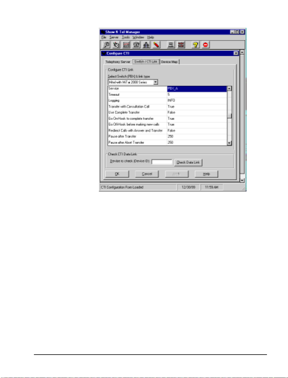
Figure 5-1 Show N Tel Manager, Switch/CTI Tab
4. From the “Select Switch (PBX) & link type” list, se lect
with MiTAI 2000 Series
• Service:
• Timeout:
• Logging:
PBX_A
5
INFO
• Transfer with Consultation Call:
• Use Complete Transfer:
• Go Onhook to Complete Tran sfer:
• Go Offhook before Making New Calls:
• Redirect Calls with Answer Transfer:
• Set the
• Set the
Pause after Transfer
Pause after Abort Transfer
.
FALSE
field to
TRUE
TRUE
FALSE
250
field to
TRUE
.
250
Mitel
.
5. Obtain a list of the trunks and lines that are configured in your
PBX.
6. Select the
Configuring Show N Tel with a PBX 69
Device Map
tab, as shown in Figure 5-2.
Page 70

Figure 5-2 Show N Tel Manager, Configure CTI, Device Map Tab
70
7. For each line you plan to run:
a. In the
Device ID
column, select an empty row and enter the
Device ID of the line or trunk from your PBX to the Telephony Server. Now, in Show N Te l version 4.4, you enter a
trunk number only as a number in the form “xxx”, where
“xxx” stands for the B-Channel trunk number you set up in
the switch (e.g., where previously you entered “T501”, it now
becomes simply “501”.)
b. Click the
Device Type
column, then select
drop-down list.
c. In the
Show N Tel Line Number
number to which you want to map.
d. Click
Apply
to accept your changes and close the Configure
CTI window.
NOTE:
a range of devices. To use the
Clone Entry
The
button lets you quickly and easily program
Clone Entry
trunk
from the
column, enter the line
button, place the cursor
Page 71

in a blank Device ID cell and click Clone Entry. When prompted,
enter the beginning and ending Device ID number.
8. To verify a trunk, enter a trunk device ID in the Device to check
(Device ID*) edit box, then click Check Data Link. A message
box should appear verifying the link. For example, a trunk is
identified in your PBX as T100. Type
then click Check Data Link. If the test passes, the PBX link and
both the AFC and MiTAI runtime software are all working.
NOTE: You do not need to edit the Telephony Server tab.
Editing the SNT Parameters Tab
1. From the Tools m enu of Show N Tel Manager, choose ShowN-
Tel Set up. The Show N Tel Setup dialog app ears.
2. Select the Parameters tab, shown in Figur e 5-3.
Figure 5-3 Show N Tel Ma nager, Parameters Tab
in Device to check,
T100
3. In the T ypes drop-down list, sele ct Voice channel parameters.
4. Set the value for VCE_Record_Gain to 75 for all voice ports.
Editing t h e SNT Para me ters Tab 71
Page 72

You al so need to ed it the Param et er s t ab if yo u us e the NMS AG-0
card (AG-8 DSP—no SIPPs; see Chapter 3 in this guide).
To edi t the Para meters tab to note the presence of an AG-0 card:
1 In the Types drop-down list, select Voice Board parameters.
The System window displays a list of SNT line numbers.
2 In the System window , select the top line supporte d by voice
ports on your line c ard(s), then, with the left mouse button down,
drag the mouse to highlight all lines supported by voice ports on
your line card(s). For example, if you have two AG-0 cards , a
total of 16 lines, highlight 1 through 16.
3 In the Value field, set the value to 1, then click Set Value. All of
the values for the highlighted lines change to 1.
4 Click Done.
NOTE: Do not use the Languages tab to choose languages (U.S.
English, U.K. English, or Spanish) for phone prompts. OnePoint
Messenger gets that information from the Syst e m Informat io n and
Mailbox Defaults pages of the Unifie d Messaging Snap-in to MMC.
See Chapter 3 in the OnePoint Messenger Administrator Guide .
Assign i ng Prog rams to Lines
OnePoint Messenger pr ovides telephon y applications t hat run through
Show N Te l Manager to provide line card services. They are:
• Active Call Handler: Supports the Active Call CTI system,
which detects port hang-ups
• AutoRecep (Automated Attendant, also called Automated
Receptionist): The general purpose “Telephony Server” application will route calls to the Automated Attendant, but you c an dedicate a li ne to AutoRecep if you want to be mo re sure that calls to
the Automated Attendant do not need to wait for a port.
• Fax on Demand: As with AutoRecep, the “T elephony Server”
application handles Fax on Demand calls, but you can assign the
Fax on Demand application to a port to provide more dedicated
service to those calle rs . Faxes sent to those calle rs who are not
receiving the requested fax at the online number must be delivered from a port running the SendFax application.
• Message Delivery: To support Quickfax, assign this to Line 50 in
Show N Tel Setup. Assigning Message Delivery to a line other
72 Chapter 7, Configuring OnePoint Messenger PBX Integration So ftw a re
Page 73

than Line 50 will work, but Line 50 is recommended for
consistency in providing remote technical support. In fact, some
turnkey systems have been shipped with Message Delivery
assigned to Line 512. Please move Message Delivery to Line 50.
NOTE: Message Delivery is also intended to support messaging
fault-tolerance ("Post Office Resiliency") in a future release.
• Notification Server: There are four versions of Notification
Server, detailed below, supporting the Call-Me service or some
form of notification of incoming unified messages.
• SendFax: Sends faxes to Fax on Demand recipients and to a user
who downloads e-mail to a fax machine that is not “online”, i.e.,
not at the number from which the caller is requesting the fax.
• Telephony Server: General purpose application that supports
messaging into and from mailboxes, Autom ated Attendant, Fax
on Demand, Meet-Me, TTS, and sending faxes.
Functions supported by the “Telephony Server” application request
and release po rts dy n amically. For example, when a fax arrives, the
Receive Fax function within Telephony Server uses a port f rom those
assigned the Telephony Server application and then releases the port
when the fax operation is done. TTS and Meet-Me sessions also
work this way.
You do not need to assign an application to a port to receive faxes, to
support Automated Attendant, TTS, or Fax on Demand. The “Te lephony Server” tele phony applica tion handles those functions, but you
can dedicate a port to one of those functions by assigning an application dedicated to the function to a port.
If you encount er straine d re sources using the port a nd line assign ment
that you configure, you can easily reassign applications (see “Reassigning Lines to Other Applications” on page 82) and revise the port
and hunt group setup on the PBX.
Assigning Programs to Lines 73
Page 74

Configuring and Testing the Notification Server
Notification Server, as noted above, is a telephony application that
provides the followin g three services through four variations in its
implementation. The three services are:
• Message Wai ting Indicators (MWI): If your PBX is set up to
send MWI to the telephones that it manages, the Notification
Server telephony application can send MWI requests to the user
for whom a telephone message arrives. It can also turn off the
MWI when the user has retrieved the message.
• Paging: If you set up some or all users to be notified, on their
pagers or remote telephones, of the arrival of all or urgent unified
messages (which are telephone calls or e-mail created in a Unified Message form), Notification Server processes those alerts.
• Call-Me: Users creating a combined telephone-computer mail-
box session using Call-Me requi re a Notification Server port.
The four versions of Notific at ion Server are:
• Notification Server (Full): Provi des the three services above
• Notification Server (CM): Dedicates a port to Call-Me
• Notification Server (Paging): Dedicate s a port to paging users
when they receive unified messa ges
• Notification Server (MWI): Dedicates a port to MWI
In summary, to invoke Notification Server:
1. In the Runtime tab of Show N Tel Manager, as described in
“Using the SNT Manager Runtime Tab to Assign Telephony
Applications” on page 76, if you are using Notification Server
(Full), Notification Server (CM), or Notification Server (Paging), assign them to Show N Tel line s that are associated with
physical ports on your line car d. The lines must have a servi ce
level that allows turning MWI on and off . If you are using Noti-
fication Ser ver (M W I ), assign it to “virtual” Show N Tel lines,
in other words, lines not associa ted with physical line card ports.
2. On the PBX, assign a line that has a service level allowing long
distance pager dialing and messa ge delive ry connecte d to the port
to which you assign Notification Server .
3. On the PBX, assign a hunt group number with a group type of
HCI Reroute to the line supporting the Message Cente r, then
enter that number in the TelSrvr.ini file under MWIPilotNum-
ber. See “Editing the Telsrvr.ini File” on page 80.
74 Chapter 7, Configuring OnePoint Messenger PBX Integration So ftw a re
Page 75

4. Reboot the system.
5. Finally, to support unified message notification through pag ers,
the Telephony Server admini strator must configure, in TSAdmin
(the Unified Messaging Snap- in to Micr osoft Management Console) the Pager Settin gs page, and set pa gin g permissi ons i n each
Class of Service on the Class of Service node. The Exchange
administrator must assign paging permissions to individual users
by selecting for the user one of the 10 Classes of Service, and by
setting pager settings. For details on those permissions, see
Chapters 2 and 3 of the OnePoint Messenger Administrator
Guide.
Notification Ser ver has a testing utility called cvNoti fy that tests
whether Notificat ion Server gene rates pa ges to a partic ular user when
a message arrives for that user and tests whe ther a Message Waiting
signal is sent to a user’s telephone when a message arrives. See
“Testing the Operation of Notification Server” in Chapter 6 of the
OnePoint Messenger Administrator Guide.
As described above, s ome appli cati ons re quire a ssig nment to ph ysic al
(real) ports, while others can be assigned to virtual ports (SNT line
numbers above those linke d to physical por t s). Table 5-1 shows those
options. Also, the functions that can only be done by an application
dedicated to that function are noted under Dedicated, while other
functions, noted under Optional, can be supported either by a dedicated application or a more general purpose application.
Table 5-1 Telephony Applications
Real
Application
Telephony Server
Speech, Automated Attendant, Receive Fax)
SendFax
downloadi ng e-mail to rem ote fax mach ines
Fax on Demand
Message Delivery
caches te lephone messages when Exchange is down )
Notification Server (CM
Chapter 3 in the
Notification Server (MWI)
to users’ extensions
Notification Server (Page)
Notification Server (Full)
: Send faxes to Fax on Demand recipients and to users
(Message Center, Fax on Demand, Text to
: Receive calls from Fax on Demand callers X X
: Supports QuickFax (will also ultimately
): Connection for Call-Me sessions (see
User Guide
)
: Send message waiting indications
: Send MWI to pagers X X
: Includes CM, MWI, and Page X X
XX
XX
XX
Virtual
Port
Port
XX
XX
Dedicated Optional
Assigning Programs to Lines 75
Page 76

Table 5-1 Telephony Applications
Application
Real
Port
Virtual
Port
Dedicated Optional
Active Call Handler
: notes call hang-ups X
Using the SNT Manager Runtime Tab to Assign
Telephony Applications
In this procedure, you use the Runtime tab, shown in Figu re 5-5, of
Show N T el Manager (SNT) t o assign On ePoint Messenger telep hony
applications to individual li nes. All of the existing OnePoint Messenger telephony applications are automatically installed and added to
the Program Information area of the tab.
1. Run Show N Tel Manager from the S how N Tel progra m group.
2. From the Tools m enu, choose ShowNTel Setup.
3. Select the Runtime tab, as shown in Figure 5-4, which shows
how the Runtime tab appears after OnePoint Messenger is
installed, with all of the OnePoint Messenger telephony applications appearing in the Program Information list, and the general
purpose “Telephony Server” application assigned to SNT Line 1.
76 Chapter 7, Configuring OnePoint Messenger PBX Integration So ftw a re
Page 77

Figure 5-4 Show N Tel Manager, Runtime T ab
4. In the
Program Information
area, select an applicati on that you
want to assign (in Figure 5-4, Telephony Server is selected.)
5. In the
Lines Information
area, select the line(s) to which you
want to assig n that application. For example, Line # 1 is selected
in Figure 5-4. You can select only contiguous lines.
6. Repeat the st eps to a ssign a n appli cati on to e ach line supporte d by
a physical port.
7. Assign
Active Call Handler
to a line not associated with a phys-
ical port.
8. Assign
Message Delivery
to Show N Tel Line 50. On some turnkey systems, it is assigned to Line 512 or another line. Please
move it to Line 50.
9. Select all of the assigned line s in the
Set Phone Sys
click
, then select
Lines Information
MiTAI AFC
, as shown in Fig-
area,
ure 5-5.
Assigning Programs to Lines 77
Page 78

Figure 5-5 Show N Tel Runtime Tab, Assign Phone System
A line is enabled as soon as you assign an application to it. An
enab l e d li ne is id entif i e d by a n “ X ” in it s
Informa tion
area.
Enabled
field in the
To deactivate one or more lines:
Lines
Select the line(s) in the
Lines
. Make sure that the “X” is gone from the
Lines Info rma t ion
area, then click
Enabled
Disable
field.
To reactivate one or more lines:
Select the line(s) in the
Lines
.
Lines Info rma t ion
area. Click
Enable
To remove an application assignment from one or more lines:
Select the line(s) in the
Lines Info rma t ion
area. Click
Clear Lines
Setting Telephone User Interface Parameters
OnePoint Messenger is insta lled with a set of default telephone interface settings that m inimiz e your ne ed to amend th em for the sy stem t o
be operational. Read Chapter 1 in the OnePoint Messenger Adminis-
trator Guide for an overview of tasks and applications and Chapter 3
in that guide for details on using the Unified Messaging Snap-in to
Microsoft Management Console (MMC) to edit the settings.
78 Chapter 7, Configuring OnePoint Messenger PBX Integration So ftw a re
.
Page 79

To access the Unified Messaging Snap-in to MMC:
1. One the Telephony Server, double-click the TSAdmin icon on
the desktop, or start Microsoft Management Console from the
Windows Start menu.
2. Select the appropriate page or node, as listed below with the
affected setting.
The following settings are those which you need to set or are most
likely to want to revise:
• Messaging Pilot Number—This is the Message Center exten-
sion which users dial to access voice mail. Use the Message
Center page of the Applications node.
• Default Fax Number—This is the phone number of a fax
machine that acts as the default destination of faxes and e-mail
that users download to a "Personal F ax Number" when they
retrieve messages. Use the System Information property page in
the System Configuration node to set the number.
The Exchange Administrator can change the phone number on a
per-user basis in each user’s Exchange profile. Each user can do
so via the TUI.
• Enable Operator—Enter your operator’s extension number in
the Attendant Extension field on the Attendant Configuration
page. Users will dial 0 and be routed to this extensi on.
• Autom at ed Attendant— Enter the Automated Attendant extension number in the associated Pilot Number field that you
assigned in “Programming the Automated Attendant (Receptionist)” on page 43 in Chapter 3 here. Use the Automated Atten-
dant page of the Applications node. On that page you can
specify whether to invoke a menu or invoke the Simple Attendant, and you can set Automated Attendant greetings.
• Attend ant M a ilb ox number—Use the S y s tem I nfo rmation
property page in the System Configuration node to assign a
mailbox that collect s voice messa ges from callers who do not
enter a specific conta ct exte nsion when prompted. You can use
the mailbox number of the Telephony Server administrator or
another mailbox. If you enter another mailbox number, you must
also create the mailbox in Exchange. See Chapt er 2 in the
OnePoint Messenger Administrator Guide for details
Setting Telephone User Interface Parameters 79
Page 80

• Fax on Demand—Enter the Fax on Demand pilot number in the
Fax on Demand page of the Applications node.
• TUI prompt lan g ua ge—T o change the default prompt language
(U.S. English) used by the Telephone User Interface outside of
mailboxes, use the Syste m Information page. To change the
default prompt language (U. S. English) used by the Telephone
User Interfa ce inside of mailboxes, use the Mailbox Defaults
page under the System Configuration node.
Editing the Telsrvr.ini File
T o enable Message Waiting signals to be sent from OnePoint Messenger to users’ extensions and pagers, the MWIPilotNumber entry
in the telsrvr.ini file must be associa ted with the Message Center
pilot number of OnePoint Messenger, as created on the PBX.
To enter the Message Center pilot number in the telsrvr.ini file:
1. Open a text editor such as Windows Notepad.
2. Use the editor to edit the telsrvr.ini file that is in the directory
C:\SNT\Telsrvr.
3. Scroll through the file until you find the following entry:
MWIPil ot Num be r =
4. To the right of the equals sign, enter the pilot number of the Telephony Server Message Center, as programmed on the PBX.
This is the number of the HCI Reroute that you entered in Hunt
Group Assignment (see “Assi gning a Hunt Group to the Message Center” on page 39 in Chapter 2 for more information.)
5. Click Save, then exit.
Testing Telephony Server Start and Stop
1. Reboot the Telephony Server.
2. Click the Windows Start button, then choose Programs, then
OnePoint M ess en g er, then Telephony Server Monitor
(TSMon). For de tails on TSMon, se e the online help or C hapter 5
in the One Point Messenger Administrator Guide.
3. In Telephony Server Monitor (TSMon), c lick the Start button.
Alternativel y, choose Start from the File menu (or Ctrl+F7 ).
80 Chapter 7, Configuring OnePoint Messenger PBX Integration So ftw a re
Page 81

4. Observe that the Telephony Server services are listed in the task
monitor window, and their operational mode changes from
Stopped to Running.
5. To stop services, click either Stop or Stop Immediately.
Observe that the Telephony Server services change to Stopped.
Configuring OnePoint Messenger to Auto-start
OnePoint Messenger insta lls with Telephony Server configured for
manual starting and stoppi ng. After you have tested operation in a
manual mode, you can set services to start automatically on a reboot.
NOTE: If your AFC card has the synch ron ization daughterboard, the
Telephony Server can continue running through an SX-2000 redundancy switchover. However, if the SX-2000 is shut down and
restarted, you must reboot the Telephony Server.
1. Double-click the OnePoint Messenger folder located on the
desktop of the Telephony Server.
2. Double-click the Telephony Server Monitor icon.
3. From the File menu of Telephony Server Monitor , choos e Set the
Tserver to Start Mode Automatic.
4. From the File menu, choose Exit.
5. Click the Windows Start button, then choose Run, then enter:
C:\NMS\AG\Demos\AGMSVC\AGCFG.EXE -install
6. From Windows NT Explorer, delete NMS Star t from the star-
tup folder. The path is typically:
C:\WINNT\Profiles\All Users\Start Menu\Programs\
Startup\ NM S Sta r t
7. Restart your Telephony Server.
NOTE: You should run NMS Start once for each new hardware configuration before setting the system to auto-start.
Running the Telephony Applications
If, in Telephony Serve r Monitor, you have set Telephony Server services to start automatically when the computer boots, services will
Running the Telephony Applications 81
Page 82

start without requiring you to log in. If you have not set services to
auto-start, use Telephony Server Monitor to start them manually.
If services are alre ad y started , you can stop and start individual telephony applications by selecti ng the line in the Operate and Monitor
window of Show N Te l Manager, then using the Start and Stop commands, for tasks such as realloc ating resources. Do not stop Show N
T el through Operate and Monitor, because Operate and Monitor does
not control all Telephony Server services.
Reassigning Lines to Other Applications
You can quickly reallocate telephony applicati on resour ces. For
example, if you are running a faxback syste m and tempor arily need
more lines for Fax on Demand, you can replace some Telephony
Server line assig nments wi th Fax o n Demand. If you a dd anothe r line
card, you can easily append the new line assignments to the current
assignments.
1. Start Show N Tel Manager.
2. From the Tools m enu, choose Operate and Monito r. The Oper-
ate and Monitor Show N T el window appears, as in Figure 5-6.
82 Chapter 7, Configuring OnePoint Messenger PBX Integration So ftw a re
Page 83
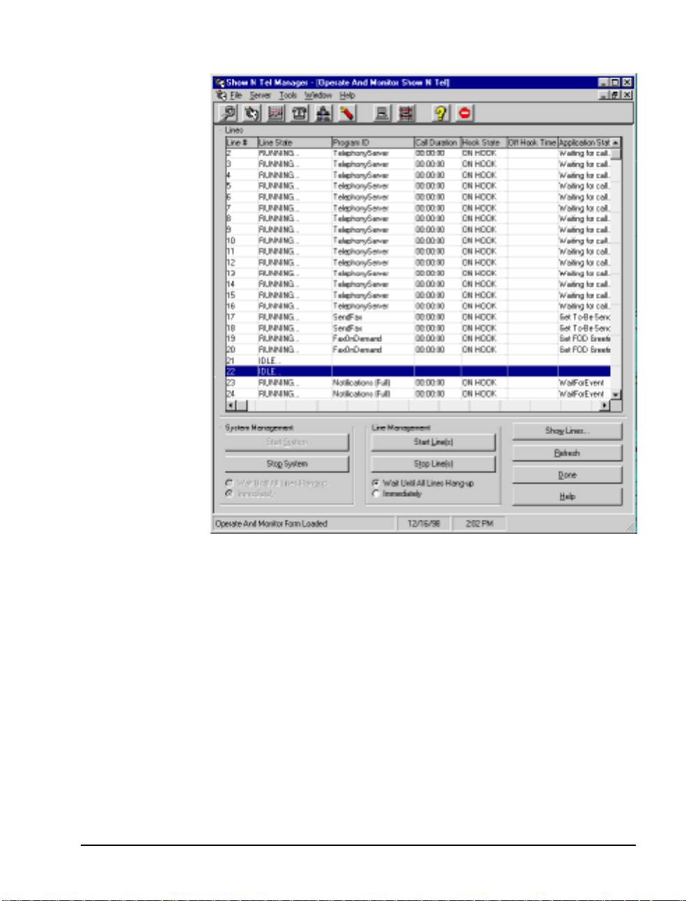
Figure 5-6 Show N Tel Mgr, Operate and Mo nitor Show N Tel Window
g
y
CAUTION!
Operate and Monitor
in the
Use the
Start System
dialog of Show N Te l only in
Stop System
and
buttons
testing mode and under direction from Product Technical Support. Other OnePoint Messenger se rvices are not controlled by
those buttons. Instead, use TSMon, as described on page 80.
3. Select the lines that you want to reassign, then click
4. From the
5. Select the
Tools
menu, choose
Runtime
tab, as shown in Figure 5-4.
6. Select the line(s) to reass ign in the
select the application to assign in the
area, then click
Running the Telephony Applications 83
Assign Program
ShowNTe l Setup
Lines Information
Program Information
.
Stop Line(s)
.
area,
.
Page 84

7. If your new applic ation re quire s a change in t he set up on the P BX
of the line connecting to the associated port, make the change on
PBX before restarting the line .
8. Switch to the Operate and Monitor Show N Te l window, as
shown in Figure 5-6.
9. Select the lines that you reassigned, then click Star t Lines.
84 Chapter 7, Configuring OnePoint Messenger PBX Integration So ftw a re
Page 85

6. Troubleshooting the
Integration
This chapter covers system validation tests and troubleshooting. It
contains these sections]
Section Page
System Validation Tests 85
Testing the Network Connection 86
System Validation Tests
The rigorous way to ensure a successful installation is to continually
validate as you install components. Validation is the process of
inspecting and te sting to make sure that components are installed and
operating corr ectly when there is no evidence of a problem. Performing timely validation reduces the set of possible problems that must
be considered when a problem occurs.
For that reason, the OnePoint Messenger Installation Guide and this
integration guide contain valida tion tests in each chapter that validate
the successful installation of the components covered in that chapter.
In addition, the OnePoint Messenger software suite include s the Version Reader validation utility for checking build levels, and the
OnePoint Messenger components fully utilize native Windows NT
diagnostic capabilities, augmented by MiTAI logs, NMS logs, the
Operate and Monitor window in Show N Tel, and SNT Trace and
OnePoint Messenger Trace Manager. See Chapter 5 in the OnePoint
Messenger Administrator Guide for a survey of those uti lities and
logs.
Running Validation Tests
The Event V iewer of both the Exchange and Telephony Server computers can be checked to see what messages were generated by the
installati on process. On startup, the Show N Te l Error Log is also a
OnePoint Messenger/SX-2000 Integration Guide
, Issue 2, 12/14/00 85
Page 86

useful place to check to see that hardware is communicating. Error
messages in that log sugge st hardwa re configur ation c onflicts. Errors
in the NT Event Log on inst allation indicate that you should consider
reinstalling or at least getting outside help.
Te st ing the Network Connection
The following sequence pres ent s a basic network “ping” test.
1. Log on to the Telephony Server as TSAdmin.
2. Select your domain name from the Domain drop-down list, then
click OK.
3. From the Windows Start menu, choose Programs, then Com-
mand Prompt.
4. In the Command Prompt window type:
ping <IP address>
<IP address> is the IP address of the Telephony Server
5. The screen should display:
C:\>ping <server name>
Pinging <servername>.<domain Name> [IP Address] with
32 bytes of data:
Reply from <IP Address>: bytes=32 time=20ms TTL=128
Reply fr om <I P Ad dr ess>: bytes =32 time=1ms TTL=12 8
Reply from <IP Address>: bytes=32 time=44ms TTL=128
Reply fr om <I P Ad dr ess>: bytes =32 time=2ms TTL=12 8
6. Carry out the same test, pinging the Network Gat eway and the
Exchange Server by name.
86 Chapter 6, Troubleshooting the Integration
Page 87

A. PBX Inte gration W orks heet
This appendix provides a workshee t fo r mapping PBX lines to Telephony Server lines. It contains these sections:
Section Page
Wor kflow Overview 87
PBX Integration W orksheet (Sample of a completed
worksheet)
• Numbe ring Po rt s
• Creating Hunt Groups
PBX Integration W orksheet 91
Workflow Overview
Use the PBX Integration Worksheet provided at the end of this
appendix to list the PBX trunks that are to be connecte d to the Telephony Server and their associated Show N Tel lines and telephony
applications. The wor ksheet c an be used to pl an the line assi gnments,
edited to note changes from the plan, and archived to maintain a
record of those mappings and the installed cards.
Edit the worksheet in this sequence:
1 Enter the computer name and IP of the Telephony Server.
2 Complete the last four columns—Line Card Type and Slot,
87
89
89
Line Card Port, SNT Line, and Telephony Applicatio ns—
while making notes by the pilot numbers on which to create and
how to provide their hunt groups, whether discrete or overlapping.
3 The PBX technician completes these parts of the works heet:
• The pilot numbers and hunt groups
• The first column—Ext./Trunk
4 The OnePoint Messenger installer uses the completed worksheet
to install the cards in their assigned slots, configure the software,
and validate the correct operation of each port, then note on the
OnePoint Messenger/SX-2000 Integration Guide
Issue 2, 12/14/00
,
87
Page 88

worksheet any changes from the plan. For details on mapping
Show N Te l lines to trunks and assigning telephony applications,
see “Show N Tel Setup Procedures” on page 68 in Chapter 5.
5 After checking the work, the project manager should enter the
completion date, then copy the works heet for the use of the Telephony Server administrator before archiving it in the project file.
A sample of a completed worksheet on page 90 shows a Telephony
Server with three AG-8 cards and a fax card. The three dialed services have been given pilot numbers and overlapping hunt groups.
T ypically, an SX-2000 integration uses a Mitel AFC card, which has
a fiber connection, to handle all calls, so there is no need to fil l in the
Slot and Line Card Type Column, other than noting
PBX Integration Worksheet Fields
The fields in the works h eet are:
• Configuration Completion Date: The date when the full
configuration was complete and validated
• Telephony Server Name and IP: The Windows NT domain
computer name and TCP/IP address; the IP can correlate the
archived worksheet with the Te lephony Server if the server is
renamed after the worksheet is archived.
• Pilot Number: The phone numbers to di al to access e ach service.
Enter these numbers in t he Messaging, Au tomated At tenda nt, a nd
Fax on Demand pages of TS Admin. See “Setting Telephone
User Interfa ce Pa ram et ers ” on page 78 in Chap t er 5 for det ail s.
• Hunt Group: The extensions accessed by the associated pilot
• Ext./Trunk#: The telephone extension numbers or trunk
numbers assigned on the PBX. The service level of a line must
support the associated Telephony Server function.
• Slot and Line Card Type: The line card model and the
Telephony Server slot in which it is inserted, counted from the
left edge of the backplane, as viewe d from the back of the
Telephony Server
• Line Card Port: The number of the Telephony Server line card
port to which the associated PBX line is attac hed. In the case of
the AG-8, each connector on the card hosts two ports. The
connector close st to the LED on the bracket of the line card hosts
Port 1A and 1B, the next hosts 2A and 2B, and so forth.
88 Appendix A, PBX Integration Worksheet
Page 89

• SNT Line: The Show N Tel line associated with the line card
port. Enter these lines on the Device Map tab of Show N Tel.
See Chapter 5 (“Configuring Show N Tel with a PBX” on
page 68) for details .
• Telephony Application: The application that runs on the
associated line. Assign these applications in Show N Tel
Manager Runtime. See “Assigning Programs to Lines” on
page 72 in Chapter 5 for details.
NOTE: Use this worksheet with the directions in Chapter 2 (see
page 25) to program the PBX, Chapter 3 (see page 45) to connect the
lines between the PBX and the Telephony Server, and Chapter 5
(page 67) to configure Telephony Server software.
Numb ering Port s
For the SX-2000 integration usin g an AFC card, the job of physically
matching lines to ports is obviated, because the AFC card gangs the
ports into a single fiber connect ion, simplifying setup. In the sample
of a completed worksheet on page 90, the Slot and Line Card Type
column shows only the AFC card. The next page of the worksheet
would show the other three ports supported by the AFC card, and the
slots that the DSP card(s) and fax card(s) occupy.
The Line Card Port column does not contain entries in this case,
because the AFC card has only one connection. Actually, it has two
connections—a TX (send) and an RX (receive).
Creating Hunt Groups
In the example, the Message Center hunt group is compri sed of extensions using two number sequences. This can occur when there is not
a large enoug h group of seque ntial extensions a vaila ble t o provide the
desired hunt group size.
In the example , the Automated Attendant ha s a pilot number th at call s
the same hunt group as that assigned to the Message Center, giving
callers to each service the same priority for accessing connections to
the two services. The Fax on Demand pilot number, in addition to
having access to the Message Center hunt group, has access to two
lines dedicated to i t, giving it the highest priority of the three services.
For a discussion of options in setting up pilot numbers and hunt
groups, see “Integration Strategy” on page 16 in Chapte r 1.
Workflow Overview 89
Page 90

PBX Integration Worksheet
(
Sample of a completed
worksheet)
Configuration Completion Date: 6/1/00
Telephony Server Name: AllwaysUp IP: 128.52.12.1
Service Pilot Number Hunt Grou p
Automated Atten da n t
Fax on Demand
Message Center
Ext./Trunk#
Trunk 100 Slot 1: AFC 1 Telephon y Server
Trunk 101 “ 2 “
Trunk 102 “ 3 “
Trunk 103 “ 4 “
Trunk 104 “ 5 “
Trunk 105 “ 6 “
Trunk 106 “ 7 “
Trunk 107 “ 8 “
Trunk 108 " 1A 9 “
Trunk 109 “ 1B 10 “
Tr unk 11 0 “ 2A 11 “
Slot and
Line Card Type
5001 use Message Center hunt group
5002 Extensions 5102, 5103 + Message Center hunt group
5000
Extensions
Line
Card
Port
5103–5108, 5201–5210
SNT
Line
Telephony
Application
Trunk 111 “ 2B 12 “
Trunk 112 “ 3A 13 “
Trunk 113 “ 3B 14 “
Trunk 114 “ 4A 15 Notification (Full)
Trunk 115 “ 4B 16 “
Trunk 116 " 1A 17 SendFax
Trunk 117 “ 1B 18 “
Trunk 118 “ 2A 19 “
Trunk 119 “ 2B 20 “
Trunk 120 “ 3A 21 Fax on Demand
90 Appendix A, PBX Integration Worksheet
Page 91

PBX Integration Worksheet
Configuration Completion Date:
Telephony Server Name: IP:
Service Pilot Number Hunt Grou p
Automated Atten da n t
Fax on Demand
Message Center
Ext./T runk#
Slot and
Line Card Type
Line Card
Port
SNT
Line
Telephony
Application
PBX Integration Worksheet 91
Page 92

92
Page 93

Index
A
Active Call CTI
Active Call Han dler telephony app lication
Address for Message Control
AFC
45, 57
AFC card
installing
synchroniz ation daughterboard
AFC driver
AFC drivers
AG-0
46, 57, 72
AG-24
46, 57
AG-8
46
Alarm Debounce Timer
Alert Device
Always Alternative number
Applicat ions node of TS Admin
ARS
39
Assigning Progra ms to Lines
Attendant Configuration pa ge of TS Admin
Attendant Mailbox number
Auto Logon
Automated Attendant
hunt group and pilot
Programming the
setting greeting for
Automated Rece pt ionis t (se e Automate d Att en-
Automatic Route Selection (ARS)
AutoRecep telephony application
64
dant)
72
72
34
57
81
57
35
40
41
80
72
79
79
13
16, 26, 27, 79
89
43
79
27
29
72
B
B8ZS Zero Code Suppression
BER
35
Board Type
British English
Brooktrout fax card
Brooktrout Tec hnology TR-114 fax cards
55
72
12
35
51
C
Cabinet Assignment form
Call flow overview
Calling Line Informati on (CLI)
Call-Me
Call-Me/Meet-Me
CEPT card
Circular hunt group
Circular hunt mode
Class of Restr iction
Class of Restriction (COR)
Class of Service
Class of Service node of MMC
Clock Ref
COS 64
CR Always
CRC
CSU
CTI
CTI Server
CvNotify (Notifications validation tool)
28
31, 36
31, 37
55
39
29
35
35
31
34
33
14
26
26
38
39
27, 43
37
75
D
DASSII
Data Call Alternate Digit Inversion
Default Fax Number
Dialed ser v i ce s
DID fax
Digital Link Assignment
Digital Link Assignment form
Digital link des criptor
Digital Link Fault Delay Timer
Digital Trunks
Direct Answer to Int ernal Messa g e
Directory Number
Directory Number 7999
Documentation
36
79
25
26
35, 36
27
41
16, 21
OnePoint Messenger
PDF versions of
35
36, 41
36
35
13
29, 39
19–24
21
75
OnePoint Messenger/SX-2000 Integration Guide
, Issue 2, 12/14/00 93
Page 94

text conventions used in
other
21
thir d p ar ty
DPNSS
Driver, AFC
DSP
57
DSX
35
DTRX Herald Message
Dual Seizure Priority
19
31, 36
64
36
32
22–23
E
E1 Line
Enable MVI P
Exchange
35
55
Extension defined
10
F
Fax card
installing on Telephony Server
compatible Brooktrout products
products supported by OnePoint Messe n-
ger
46
Fax DID
Fax on Demand
Fax on Demand page of TS Admin
Fax on Demand telephony application
Fax services, managing
Fiber distributed digital service unit
Fiber distributed systems
Fiber Link Synchronization
Fiber links
Field Change Instructions (FCI)
Forms ch ec k li st
Forms, SX-2000
Forward to Personal Greet ing
Framing Losses
26
11, 16, 27
hunt group and pilot
33
29
33
35
89
21
33
59
57
13
51
80
72
33
G
Go Offhook before Making New Calls field
Go Onhook to Complete Transfer field
Greetings, edit
Grounding strap (Earth)
11
59
69
69
H
Hardware, switch integration
HCI link
HCI Reroute
HCI Traffic Level
HCIReroute
Hosts file, editing
Hunt group
Hunt groups
Hunt Mode
38
29, 41
33
40
65
41
assignment
Message Center
39
89
38, 40
circular
Fax on Demand
39
39
44
68–72
I
I/O Base Address
Inst allation
OnePoint Messenge r sources of instruc tion
requisit e skills of installer
Installation Guide, organization of
Integ r at ed Digi ta l A ccess
Integration benefits
Interrupt (IRQ), setting the
ISDN BRI Mode
49, 55
9
19
20
34
12
55
36
L
Languages tab
Latin American Spanish
Line ca rds
installing on Telephony Server computer
Line Encoding
Link Descriptor Assignment
72
72
compatible NMS products
enabling Mitai/AFC
setting up and configuring NMS p rod-
ucts
53–56
53
57–59
55
34
M
Mailbox Defaults pag e of TS Admin
Mailboxes, creating
Manuals
OnePoint Messenger
16, 21
20–24
80
94
OnePoint Messenger/SX-2000 Int egr ation Guide
Page 95

PDF versions of
text conventions used in
thir d p ar ty
Manufacturer’s Feature Resource Dimension
19
21
22–23
32
Maximum Network Hops, Fax on Demand
Messag e C en t er
defined
hunt group and pilot num ber
Message Center hunt group
Message Delivery telephony application
Messag e N o tificat i on
message URL
http
Message Wait in g
Message Waiting Indicator
Messaging fa ult-tolerance
Messaging Pilot Number
Microsoft Certified Systems Engineer techni-
Microsoft Management Console
MiTAI
57
checking the PBX link
installation
installing Telephony Server to enable
MiTAI 7.5.3
MiTAI CD-ROM
Mitel Applica tion Fiber Controller (AFC)
14, 26
16
13
//www.mitel.com
16, 75
cian cert i fi c at io n
61
57
57
89
39
24
27
73
79
19
75
65
44
72
57
45,
57
Mitel SX-200
Mitel SX-2000
Mitel Telephony Application Interface (Mi-
MSDN-DPNSS-DASSII Trunk Circui t De-
MTAIX
Multip le Use Po r ts
Multi-Vendor Integration Protocol (MVIP)
Music On Hold
MVIP Stream
MWI
28
MWIPilotNumber
TAI)
scriptor
65
25
25
57
36
13
48
32
55
39
N
Natural MicroSystems (NMS) line cards
12
NIGHT RAD
NMS
46
NMS card
NMS Configuration
NMS line cards
Notification Server
modifying phone system definition for
Notification Server telephony application
NT (See Windows NT Server)
40
38
53
57
27, 74
O
OnePoint Messenger
Administrator Guide
configuring auto-start
described
documentation for
requisit e skills for installation of
User Guide
utilities
21
OnePoint Messenger/SX-200 Integration
Guide, conventions
Operator, Enable
Other documentation
Outdial lines
Out d ial port s
Outgoing faxes
27
27, 28
9
16, 21
9–10
20–21
21
79
21
26
P
Pager Settings page of MMC
Paging
27, 28
assigning permissi ons for
Pause af t er A bo r t Tra n sf er
Pause aft er Tr an sf e r
PBX forms checklist
PBX Integration Worksheet
PDF versions of manuals
Phase Timer
Pilot numbers
Ping
86
Port Numbering
Post Office Resiliency
Programming the SX-2000 LIGHT
Public Network Access via DPNSS
40
69
29
21
89
89
73
75
73
81
19
22
75
75
69
87–91
25
31
Index 95
Page 96

Q
QuickFax
72, 75
R
RAD1, RAD2
Redirect Calls with Answer Transfer field
Route Assignment
40
69
41, 42
S
Satellite Link
Satellite PBX
Send Fax
SendFax telephony applicat ion
Server Hosts file
editing
Show N Tel
setup
Show N Tel Runtime
Show N Tel Manager
Single Line Assignment Form
Slip Rate
Spanish, Latin America n
Speed Call Assignment form
Station Service Assignment Form
Stations, client
SUPERSET Callback Message Cancel Timer
Supporting pag ing
Switch integration
SX-000 forms checklist
SX-200
SX-2000
programming
redundancy switchover
System Configuration Form
System Configur ation node of TS Admin
System Informati on property pa ge of TS Admin
System Options Assignment form
System S p ee d Cal l As si g n men t fo r m
System validation tests
35
36
28
65
28
tab illust rations
using to integrate PBX
69
35
72
31
32
27
67–72
29
25
25
25
80
79
85
73
67–72
39
40
39
81
33
79,
32
40
T
TAPI
45
Call Control
Monitor Allowed
Technical Publications, Contacting Mitel
Telephony Applications
Telephony Server
application in Show N Tel Manager
described
editing the Telsrvr file
inte g ra t io n wi th a s w it ch ( P BX)
operating and maint aining
telephony applications provided by
Telephony Server computer
defined
Telephony Server telephony application
Telephony User Interface, configuring
Telsrvr.ini
Terminal hunt group
Text-to-Speech (TTS) dictionary, editing
Threshold
TR114 fax card
Transfer with Consultation Cal l field
Troubleshooting
Trunk Assignment
Trunk Assignment form
Trunk circuit desc riptor
Trunk Circuit Descriptor Number
Trunk Group Assignment
Trunk Group Busy, Fax on Demand
Trunk Service Assignment
Trunk Service Assignment form
Trunks
28, 31
TS Admin (Unified Messaging Snap-in)
TUI prompt language
Tx Line
35
31
31
72
11
10
39, 80
38
40
51
85
38
37
37
38
80
U
U.K. English
U.S. English
Unified Messaging
Unified Messaging Snap-in
Use Complete Transfer field
User mailboxes, creating
Utilities, OnePoint Messenger
72
72
9
16, 21
24
73
80
67
21
72
73
21
11
69
36
44
37
37
75
75
69
21
96
OnePoint Messenger/SX-2000 Int egr ation Guide
Page 97

V
Voice Board parameters, Show N Tel
Voice Co d ecs
55
W
Windows NT
service pack
Windows NT 4.0 Server
Windows NT Server
applications used in Telephony Server
Worksheet, PBX Integration
57
57
87–91
72
11
Index 97
 Loading...