

Page 1

OnePoint Messenger/SX-200 Guide
Page 2

NOTICE
The information contained in this document is believed to be accurate in
all respects but is not warranted by Mitel Corporation (MITEL). The
information is subject to change without notice and should not be
construed in any way as a co mmit ment by MI TEL or any of it s af fi liates or
subsidiaries. MITEL and its affiliates and subsidiaries assume no
responsibility for any error or omissions in this document. Revisions of
this document or new editions of it may be issued to incorporate any
such changes.
Nothing in this document may be reproduced in any manner, either
wholly or in part for any use whatsoever, without written permission from
Mitel Corporation.
Host Command Interface, HCI, MITEL, MiTAI, NuPoint Messenger,
NuPoint Voice, NuPoint Fax, NuPoint Agent, OnePoint Messenger,
SUPERSET, SX-200 and SX-2000 are trademarks of Mitel Corporation.
Windows 95 and Windows NT are trademarks of Microsoft Corporation.
INTEL and Pentium are trademarks of Intel Corporation.
All other product names specified in this document are trademarks of
their corresponding owners.
OnePoint Messenger/SX-200 Guide
OnePoint Messenger Release 2.0
Part number: 9164-120-115-NA, Rev. A
August 9, 2000
â, ä
, Trademark of MITEL Corporation.
Ó Copyright 2000, MITEL Corporation.
All rights reserved.
Printed in Canada.
Page 3

OnePoint Messenger/SX-200 Integration Guide
Table of Contents
About This Guide ............................................................................9
How to Use This G u id e ............... ............. .. .. .............. .. ............. .. .. .............. .. 9
Book Organization ................................................................................................ 10
Chapter Organization.................... ....... ...... ....... ...... ....... ...... ...... ....... ...... ....... ...... . 10
Using Electronic and Printed Versions............................................................... 10
Conventions U s e d in Th is G u id e ............ ............. .. ... ............. .. ............. ... .. 10
Keys, Commands, and Buttons........................................................................... 11
Images and Tables................................................................................................ 11
Type in Commands and Screen Output.............................................................. 12
Lists........................................................................................................................ 12
Notes and Cautions .............................................................................................. 12
Other Text Styles................................................................................................... 12
Other Documentation.................................................................................. 12
Contacting Technical Publications ..................................................................... 14
1. OnePoint Messenger/SX-200 Integration Overview...............15
What Is OnePoint Messenger and Unified Messaging? .......................... 15
Telephony Server.................................................................................................. 16
Telephony Server Peripherals................................................................................................17
Benefits of the Integration.......................................................................... 18
Call Flow Overview...................................................................................... 18
Task Overvie w .. ............. ... ............. .. ............. ... .. ............. .. ............. ... ........... 20
Integration Strategy .................................................................................... 20
2. Configuring the SX-200 PBX....................... ...... ....... ...... ....... ...2 3
Overview of OnePoint Messenger Requirements.................................... 24
Required Forms and Settings .................................................................... 25
Form 1, System Configuration............................................................................. 26
OnePoint Messenger/SX-200 Integration Guide, Rev. A, 8/9/00 iii
Page 4

Form 2, Feature Access Codes ........................................................................... 26
Form 3, COS Definitions....................................................................................... 26
Form 4, System Options....................................................................................... 29
Form 9, Desktop Device Assignments................................................................ 30
Form 11, Data Circuit Descriptors....................................................................... 30
Form 12, Data Assignment................................................................................... 31
Form 17, Hunt Group............................................................................................ 31
Form 31, System Abbreviated Dial Entry............................................................ 31
Form 34, Direct I/O................................................................................................ 33
Check MAI Installation and Programming.................................................33
Show Status Command........................................................................................ 33
Examples of the Customer Data Entry (CDE) Forms................................34
3. Installing the TalkTo Card..................................... ...... ....... ..... 39
About the TalkTo CX Card.............................. .. ...........................................39
SX-200 Support for Peripherals........................................................................... 40
Installing the TalkTo Card ...........................................................................40
TalkTo CX Card Configuration............................................................................. 43
TalkTo CX Card Settings.......................................................................................................43
Troubleshooting the TalkTo Card Installation...........................................43
Changing the IRQ.................................................................................................. 44
Changing the I/O Base Address .......................................................................... 45
4. Installing Mitel Telephony Application Interface (MiTAI)... 47
What You Need to Complete this Chapter.................................................47
Installing MiTAI on the Telephony Server..................................................47
Installing MiTAI on the Telephony Server........................................................... 47
Checking the Operation of the MiTAI Link to the PBX .............................51
Editing the Ser v e r H o s ts Fi le ............ .. ... ............. .. ............. ... ............. .. .......53
5. Configuring OnePoint Messenger PBX Integration Software55
Introduction..................................................................................................56
Integrating the Telephony Server with the SX-200 ...................... .............56
iv
Page 5

Show N Tel Telephony Applications Overview .................................................. 56
Notification Server Configuring and Testing Overview..................................... 57
Configuring Show N Tel with the SX-200 PBX..........................................59
Assigning Pro g r a m s to Li n e s .... ............. .. ............. ... .. ............. .. .............. .. 61
Modifying the Phone System Definition.................................................... 63
Setting Show N Tel Paramete rs ............ .. ............. .. .............. .. .. ............. ... .. 66
Setting OneP o in t S y s tem Parameters........... .. .. ............. .. .............. .. .. ....... 67
Editing Configuration Files for a Mitel PBX Integration .................................... 68
Editing the Server Hosts File.................................................................................................68
Editing the Telsrvr.ini file for a Mitel PBX Integration........................................................69
Starting and Stopping Telephony Server.................................................. 70
Configuring OnePoint Messenger to Auto-start ................................................ 71
Running the Telephony Applications.................................................................. 71
Reassigning Lines to Other Applications........................................................... 71
Index...............................................................................................75
OnePoint Messenger/SX-200 Integration Guide, Rev. A, 8/9/00 v
Page 6

List of Figures
Figure 1-1 Network Diagram ................................................................................................. 16
Figure 2-1 Show Status Command Display ........................................................................... 33
Figure 2-2 Form 1, System Configuration .............................................................................34
Figure 2-3 Form 2, Feature Access Codes ............................................................................. 35
Figure 2-4 Form 3, Class Of Service ......................................................................................35
Figure 2-5 Form 4, System Options/System Timers .............................................................. 36
Figure 2-6 Form 11, Data Circuit Descriptors .......................................................................36
Figure 2-7 Form 12, Data Assignment ...................................................................................37
Figure 2-8 Form 17, Hunt Groups ..........................................................................................37
Figure 2-9 Form 31, System Abbreviated Dial Entry ............................................................ 38
Figure 2-10 Form 34, Direct I/O ..............................................................................................38
Figure 3-1 Windows NT Diagnostics, Resources Tab, IRQ List ..........................................41
Figure 3-2 Windows NT Diagnostics, I/O Port List .............................................................. 42
Figure 3-3 TalkTo Card Diagram ...........................................................................................45
Figure 4-1 MiTAI Settings Dialog, Hardware Tab ................................................................ 49
Figure 4-2 MiTAI Settings Dialog, Software Tab ................................................................. 50
Figure 4-3 MiTAI Settings Dialog, Versions Tab .................................................................. 51
Figure 4-4 MiTAIX Program Window 1 ...............................................................................52
Figure 4-5 MiTAIX Program Window 2 ...............................................................................52
Figure 4-6 MiTAIX Program Window 3 ...............................................................................53
Figure 5-1 SNT Manager, Configure CTI, Device Map Tab ................................................. 60
Figure 5-2 Show N Tel Runtime Tab, Assign Phone System ................................................63
Figure 5-3 Show N Tel Setup, Phone System Tab .................................................................64
Figure 5-4 SNT Setup, Phone Sys Definition, Configure CTI Tab ....................................... 65
Figure 5-5 Show N Tel, Feature Definitions Tab ................................................................... 66
Figure 5-6 Show N Tel Manager, Parameters Tab ................................................................ 67
Figure 5-7 Telsrvr.ini ............................................................................................................. 70
Figure 5-8 SNT Manager, Operate and Monitor Window ..................................................... 72
vi Table of Contents
Page 7

List of Tables
Table 2-1 Form 2, Required Feature Access Codes .............................................. 26
Table 2-3 Form 3, Additional ONS COS Features ................................................ 27
Table 2-2 Form 3, COS Features Common to the Four COS Groups ................... 27
Table 2-4 Form 3, Additional User Set COS Features .......................................... 28
Table 2-5 Form 3, Additional MiTAI link/DNIC 2103 COS Features ................ 28
Table 2-6 Form 3, Additional MWI/Pager Notification COS Features ................. 28
Table 2-7 Form 4, System Options ........................................................................ 29
Table 2-8 Form 11, Data Circuit Descriptor, Select Option .................................. 30
Table 2-9 Form 31, System Abbreviated Dial Entry ............................................. 32
Table 2-10 Form 34, MAI Programming: Direct I/O .............................................. 3 3
Table 3-1 Base Address Locations on the TalkTo Card ........................................ 46
Table 5-1 Telephony Applications ........................................................................ 61
OnePoint Messenger/SX-200 Integration Guide, Rev. A, 8/9/00 vii
Page 8

OnePoint Messenger/SX-200 Integration Guide, Rev. A, 8/9/00 viii
Page 9

About This Guide
Use this guide to integrate a OnePoint Messenger Telephony Server
with a Mitel SX-200 PBX. I f y ou a re i nst al li ng a turnkey TS800 Telephony Server, use this guide with the OnePoint Messenger Getting
Started Guide. If you are installing OnePoint Messenger on a bare
system, use this guide with the OnePoint Messenger Installation
Guide. This integration guide replaces Chapter 4 in that guide.
This chapter contains these sections:
Section Page
How to Use This Guide 9
Conventions Used in This Guide 10
Other Documentation 12
How to Use This Guide
“Task Overview” on page 20 in Chapter 1 lists the sequence of tasks
in the installation and integration process, noting the chapter associated with the task.
OnePoint Messenger is designe d to be r elati vely s imple to impl emen t
and use. However, integrating the OnePoint Messenger Telephony
Server with a Mitel PBX requires the skills of a technic ian with certification in the programming of an SX-200 and the installation of
OnePoint Messenger. While this manual lists the critical PBX features that must be enabled and contains instructions on the use of the
PBX user interface, the instructions are for LIGHTWARE 17 and
may not be current for your system. See the manufacturer’s programming guide that accompanies your PBX software. In addition, this
manual does not discuss the array of monitoring, programming, and
troubleshooting options available to the Mitel SX-200 installer and
administrator.
OnePoint Messenger/SX-200 Integration Guide, Rev. A, 8/9/00 9
Page 10

Book Organization
This guide provides an overview in Chapter 1, followed by chapters
organized by the most appropriate sequence of activities.
• Chapter 1 (page 15): Overview of the components, tasks, and
benefits of the integration
• Chapters 2 (page 23): Configuring the SX-200 PBX
•Chapter 3 (page 39): Installing the TalkTo card on the Tele-
phony Server
• Chapter 4 (page 47): Installing MiTAI on the Telephony Server
• Chapter 5 (page 55): Configuring the Telephony Server, with an
overview of startup and shutdown procedures
• Index: In the electronic form of this guide, the index items are
hyperlinked to the associated contents.
Chapter Organization
Each chapter in this b ook u ses th e same or gani zatio n. Under t he chap ter title is a brief introduction to the chapter content, followed by a list
of the major topic headings, as exemplified above.
Using Electronic and Printed Versions
This guide uses a format that accommodates both on-screen viewing
and printing. The text is aligned to 7" by 9" borders, so that, when
printed on normal letter stock, there is a lot of room for you to make
notes. Use Acrobat Reader version 3.0 or better to view and print
PDF versions of the document.
Links: Blue text indicat es hyperl inks. The Acrobat bookmark li st and
thumbnails also provide hyperlinks. The Table of Contents (page iii)
is hyperlinked to the chapters and sections in chapters. Each chapter
contains its own hyperli nked tabl e of cont ents i n its intro ducti on. References to sections, figures, and tables are hyperlinks.
Conventions Used in This Guide
This section describes the formatting conventions used in this guide
to give you extra cues about the action that you are to take.
10 About This Guide
Page 11

Keys, Commands, and Buttons
The commands “select”, “cl ear”, “click”, and “choose ” al l me an basically the same thing—to make a choice—but the terms are used in
specific situations:
• “Choose” is used in menus, such as the Windows Start menu and
program menus, to indicate menu items.
• “Click” is used for obvious buttons, up and down arrows, in edit
boxes, spin controls, and for the Windows Start button.
• “Double-click” is us ed in any si tuat ion where pr essi ng the mou se
button twice is the most appropriate action, although other
options may be available.
• “Press” is used when indicating a computer keyboard or telephone keypad key. There are brackets around the keyboard key,
as in “Press [Tab].”
• “Select” is used on property pages (tabs) and dialogs, such as to
indicate items in a field or group of options. “Clear” is used to
deselect a check in a check box or an entry in a field.
This guide generally does not include the keyboard shortcuts for
menus and commands. To use the keyboard shortcuts, you should:
• Display menus by pressing [Alt] a nd the underlined charact er d is played on the screen (for example, press [Alt+F] for the File
menu).
• Choose commands by typing the underlined character displayed
on the screen (for example, type S for the Save command).
An instruction that involves making a choice from a menu is structured: “From the XXX menu, choose YYY.” This style is also used
for dialog boxes. As you become familiar with the style, you can
focus on the words in bold as the critical operative phrases.
Images and Tables
Tables and inline graphics in this guide contain captions with numbers based on the chapter number. References to a figure or table
from another page are linked and highlighted in blue to indicate the
link. You can also find and access them from the Acrobat bookmark
list.
When presenting information about buttons, such as “Click the XXX
button to open the YYY dialog box,” this guide may present the but-
Conventions Used in This Guide 11
Page 12

ton to the left of the instruction, as shown here. In that case, the
graphic is not labelled.
Type in Commands and Screen Output
For statements in command syntax format,
bold type like this
Brackets like these < > designate the variables that you are to replace
with other information. For exampl e, in the followi ng command, you
type the word
the names of the drive and directory you are using:
<drive>\<directory>\INSTALL
The same font in reg ular we ight ( not bo ldfac e) pre sen ts scr een out put.
Lists
Numbered lists present the steps of procedures that you must follow
in the order given.
Bulleted lists present options for which the order is not important.
Notes and Cautions
A “NOTE:” presents information that is of special importance or is
relevant only to some users or in some situations.
A “CAUTION!” alerts you to choices with potentially problematic
results.
small mono-spaced
indicates the characters you should type.
INSTALL but replace “drive” and “directory” with
“WARNING!” is more serious than a caution, alerting you to a
choice that could cause a failure of the system.
Other Text Styles
Italic type is used to introduce terms and for the titles of publications.
In this guide, boldface type is used to emphasize tasks and key
words, such as buttons, tab, and menu items, to make them easier for
you to spot. For example, a task is presented with the purpose in a
separate bold line, followed by the steps, with key words in bold.
Other Documentation
The focus of this guide is the installation of th e TalkTo card on the
OnePoint Messenger Telephony Server and the integration of the
12 About This Guide
Page 13

Telephony Server with a Mitel SX-200 PBX. This guide is not
intended to replace the manufacturer documentation for the PBX and
TalkTo card, or, in fact, the other third-party products supporting the
OnePoint Messenger unified messaging environment, such as other
peripheral hardware, Show N Tel, and Microsoft software (Outlook,
Windows, Exchange, and Microsoft Management Console).
Appendix B of the OnePoint Messenger Administrator Guide pro-
vides a list of vendor contact information.
The turnkey TS-800 ships with documentation for hardware and software provided by their respective manufacturers, including the CDROM, computer, line cards, modem, motherboard, pcAnywhere
remote management software, and SCSI adapter card.
In addition to this guide, the documentation on the OnePoint Messenger CD-ROM in Acrobat PDF format includes:
• OnePoint Messenger Administra tor Guide (summarized below)
• OnePoint Messenger Getting Started Guide (for turnke y installa-
tions)
• OnePoint Messenger Installation Guide
• OnePoint Messenger User Guide (summarized below)
• PBX integration guides for:
• Centrex switches
• Fujitsu 9600
• Lucent Definity G3
•Mitel SX-200
• Mitel SX-2000
• NEC NEAX 2400, all versions
• Nortel Meridian
• From Brooktrout Technology:
• Getting Started with Show N Tel (installing and using soft-
ware bundled with Show N Tel)
• Show N Tel System Administrator Guide (using Show N Tel
Manager)
• OnePoint Messenger Quick Reference Card
(Telephone User Interface)
Other Documentation 13
Page 14

Contacting Technical Publications
The Mitel Technical Publications and Media Development Group
maintains this document. We welcome your questions and suggestions—notes on spelling and grammatical errors, comments on readability, and suggestions for improvements. Please reference the
document number that appear s on the back of t he cover page. Add ress
your comments to:
techpubs@mitel.com
14 About This Guide
Page 15

1. OnePoint Messenger/SX-200 Integration Overview
This chapter is an overview of the in tegration between the O nePoint
Messenger™ Telephony Server and the SX-200 PBX to create a unified messaging environment. This chapter includes details on installing the line cards in the Telephony Server and setting up telephony
applications on the Telephony Server. This chapter contains the following sect ions:
Section Page
What Is OnePoint Messenger and Unified Messaging?
Telephony Server
Benefits of the Integration 18
Call Flow Overview 18
Task Overview 20
Integration Strategy 20
What Is OnePoint Messenger and Unified Messaging?
OnePoint Messenger is a software suite that, when combined with
other hardware and software products, provides a unified messaging
environment. “Unified messaging” is the storage of telephone voice
messages, faxes, and e- mail in one ce ntral re pository so that use rs can
use a PC or a telephone to retrieve both e-mail and messages sent
from a telephone.
OnePoint Messenger also provides a single point of user administration on the Exchange Server connected to the Telephony Server
through a LAN. The Telephony Server provides a messaging conduit
between the PBX and the Exchange Server, caching users’ Exchange
profile information, such as telephone passwords and greetings for
faster message access through a telephone.
15
16
OnePoint Messenger/SX-200 Integration Guide, Rev. A, 8/9/00 15
Page 16
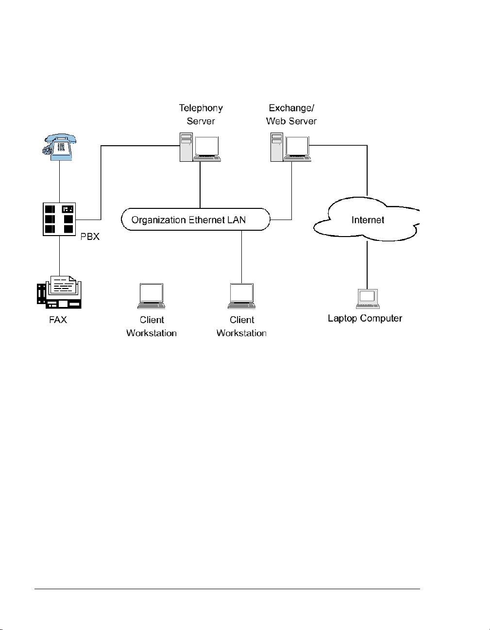
The network diagram in Figure 1-1 shows the major components that
provide the unified messaging service, examples of the clients, and
the relationship between the components.
Figure 1-1 Network Diagram
Telephony Server
In these guides,“Telephony Server” is used to refer to the collection
of OnePoint Messenger telephony applications that reside on “the
Telephony Server” (the computer running the Windows NT Server
4.0 operating system).
The OnePoint Messenger software on the Telephony Server is com-
prised of a group of Windows NT Server applications that, among
other tasks, provide the link between the SX-200 and Microsoft
Exchange.
Those telephone call routing and messaging services include:
• Controlling what happens to calls that are not answered and providing the caller the ability to leave and retrieve voice messages
• Providing digitization, transcoding, and compression of telephone messages for stora ge on Exc hange or forwarding to VPIM
16 OnePoint Messenger/SX-200 Integration
Page 17

accounts, and also reverse transcoding of messages saved on
Exchange back to callers and VPIM accounts
• Enabling OnePoint Messenger subscribers (“users”) to retrieve
and reply to e-mail messages that are read to them using the textto-speech (TTS) capabilities of Telephony Server
• Providing advanced fax handling features, including routing email to fax machines and a Fax on De mand servi ce; see Chapter 4
of the OnePoint Messen ger Admini st rator Guide for a dis cus si on
of OnePoint Messenger fax features.
For more on the RAS (support) programs, see the OnePoint Messen-
ger Administrator Guide, Chapter 1 and Chapters 5 through 9. See
Chapter 5 in that guide for operational details.
Telephony Server Peripherals
The backplane of the Telephony Server contains an Ethernet LAN
card for communication with Exchange and the telephony “line
cards” cards that provide the connection to the switch.
When integrating with an SX-200 switch, the Telephony Server contains a TalkTo CX card and one or more Natural MicroSystems
(NMS) line cards in the ISA bus (also, optionally, a Brooktrout fax
card). The connection to the SX-200 PBX is through both the TalkTo
and NMS cards. A digital line connects the Line port on the TalkTo
card to the DNIC card on the PBX. Analog lines connect the ONS
card on the PBX to four duplexed RJ-61 ports on each NMS AG-8
card.
For details on installing the TalkTo card in the TS80 0 turnkey Telephony Server, see Chapter 3 (page 39). See Appendix A of the OneP-
oint Messenger Getting Started Guide for recommendations on card
arrangement in ISA slots (“slot map”), and IRQ and I/O base address
assignment.
For an overview of installing other line cards, see Appendix B in the
OnePoint Messenger Installation Guide, then see the manufacturer
documentation.
Modem: To provide remote technical support, connect a modem to a
Telephony Server serial port and to an outside telephone line, then
configure the program pcAnywhere, which is included with the turnkey TS-800 system, to communicate over that modem and allow offsite support to control the Telephony Server.
What Is OnePoint Messenger and Unified Messaging? 17
Page 18

Benefits of the Integration
The integration between the PBX and the Telephony Server provides
these benefits:
• Forward to Personal Greeting: Provides the ability to play a
user’s personal greeting to a caller who has been forwarded to
voice mail.
• Auto Logon: The Te lephony Server can recognize a caller as a
OnePoint Messenger subscriber ( “user”), r ather tha n as an out side
caller, when calling directly from the user’s phone. The Telephony Server greets users by name and asks for their passcodes.
• Multiple Use Ports: Allows use of the same port for dynamic
allocation of ports for the Automated Attendant, the Message
Center, including Text-to-Speech e-mail access, or fax services.
• Direct Answer to In ternal Message: Allows a messa ge recipient
to record an answer to a message from another user without having to first dial the user’s extension.
• Message Notification: Allows the Telephony Server to send a
message waiting notifi cation to a use r through the PBX. The PBX
then activates the message waiting indicator, such as a light or a
stutter dial tone, on the user’s extension.
Call Flow Overview
This is a basic overview of the processing sequence of calls routed
from the SX-200 PBX to the Telephony Server:
1. The PBX receives a call intended for an extension managed by
the PBX.
2. If the call is to a OnePoint Messenger user whose phone is busy
or is not answered, the PBX redirects the call to the Telephony
Server. The PBX also directs calls to the Telephony Server that
are forwarded by users to voice mail, or users who make a direct
call to the Message Center (the mailbox access pilot number) on
the Telephony Server.
Other T ele phony Server s ervices can be associat ed with parti cular
phone numbers, such as t he Auto ma te d Att end ant and the Fax on
Demand service. For details, see Chapter 3 in the OnePoint Mes-
senger Administrator Guide.
18 OnePoint Messenger/SX-200 Integration
Page 19

3. The call arrives at the Telephony Server in two streams of data:
• The call itself goes to a port on the NMS card. The card has
four physical ports, each of which handles two loop start
phone lines.
• The calling data goes to the TalkTo card. This includes the
caller’s phone number, called party’s phone number, and the
reason code why the call was sent to the Telephony Server;
this is also known as CLI, or calling line identification.
4. The NMS card detects th e call and al erts Telephony Server. At the
same time, the TalkTo card passes the CLI data to Te lephony
Server software that uses the ca lled n umber to det ermine whether
to play a system greeting or a user’s greeting. The TalkTo card’s
role is complete for this call.
5. Telephony Server maintains a cache of user profile information,
including digitize d greetings. The appropr iate greeting loads from
the Telephony Server onto the NMS card, which converts it to
analog speech and plays it to the caller.
6. The Telephone User Interface (TUI) on the Telephony Server
sends the appropriate digitized prompts to the NMS card for conversion and playing to the caller. For example, if the call is for a
user, the TUI pr ompts t he calle r with t he messa ging op tions avail able, such as to record or re-record a voice message, or to l ea v e a
fax.
7. The caller responds with a voice message or keypad input.
8. The NMS card converts the analog input from the caller (the
voice message and keyed responses to prompts) into digital
strings for Telephony Server. The NMS card routes fax messages
through the Brooktrout card.
9. T el epho ny Server package s the ca ller’s message into a digit al fil e
and routes it to the recipient’s mailbox on the Exchange Server.
Reciprocally, when users retrieve voice messages from a telephone,
the NMS card converts the stored digitized voice messages back into
analog voice for delivery to the user.
Call Flow Overview 19
Page 20

Task Overview
1. Install ONS and DNIC digital line cards on the SX-200 PBX,
2. Install and configure the TalkTo card on the Telephony Server.
3. Install and configure the NMS AG-8 cards and Brooktrout card
4. Install the MiTAI 7.5.3 software on the Telephony Server, then
5. Install the OnePoint Messenger software on the Telephony
6. Configure Show N Tel and the other Telephony Server software
Integration Strategy
then configure the PBX to communicate with the Telephony
Server. See Chapter 2 (page 23).
See Chapter 3 (page 39).
on the Telephony Server. See the manufacturers’ documentation
and Appendix B in the OnePoint Messenger Installation Guide.
configure MiTAI for the TalkTo card and the SX-200. See Chapter 4 (page 47).
Server. See Chapter 6 in the OnePoint Messenger Installation
Guide.
to communicate with the PBX. See Chapter 5 (page 55).
OnePoint Messenger provides three services that you can set up so
that callers can access any one of them by dialing unique pilot numbers. They are Automated Attendant (automated receptionist), Message Center (access to mailboxes), and Fax on Demand (faxback).
Typically, to be able to provide optimum access to each service, you
would create a hunt group for each, the total lines of which would
match the number of lines attached to the Telephony Server assigned
to incoming calls. For the SX-200 integration, however, you must
route calls to the Auto mated Attendant and Fa x on Demand through
the Message Center pilot. Chapter 2 (page 23) here describes creating
subscriber extensions for Automated Attendant and Fax on Demand
(often called phantom extensions), set up to forward all calls to the
Message Center pilot.
On the Telephony Server side, you would normally be able to assign
applications to certain ports that would be dedicated to providing
either the Automated Attendant or Fax on Demand service. For the
SX-200 integration, you must assign the Telephony Server telephony
application to all inbound ports. The Telephony Server telephony
application is a general purpose application that provides all three
20 OnePoint Messenger/SX-200 Integration
Page 21

dialed services (Automated Attendant, Message Center, and Fax on
Demand). The correct se rvi ce ans w er s b ase d on the pilot number t hat
the caller d ials.
Notifications and Se ndFax ar e outbound applications t hat require outdial ports on the PBX.
Integration Strategy 21
Page 22

22 OnePoint Messenger/SX-200 Integration
Page 23

2. Configuring the SX-200 PBX
This chapter contains required PBX settings to enable OnePoint Messenger unified messaging. This chapter contains these sections:
Section
Required Forms and Settings 25
Form 1, System Configuration 26
Form 2, Feature Access Codes 26
Form 3, COS Definitions 26
Form 4, System Options 29
Form 9, Desktop Device Assignments 30
Form 11, Data Circuit Descriptors 30
Form 12, Data Assignment 31
Form 17, Hunt Group 31
Form 31, System Abbreviated Dial Entry 31
Form 34, Direct I/O 33
Check MAI Installation and Programming 33
Examples of the Customer Data Entry (CDE) Forms 34
Page
For details on SX-200 programming proce dures, se e your Mitel documentation:
• For details on data entry, refer to the Mitel Practice, SX-200 PBX
Customer D ata Entry (CDE) (91xx-yyy-210, where xx is the
product designator and yyy is the software release).
• For specific information on ONS voice mail setup, see the document SX-200 EL-ML Technical Documentation–Release 3.1
OnePoint Messenger/SX-200 Integration Guide, Rev. A, 8/9/00 23
.
Page 24

• On the Mitel SX-200 EL/ML LIGHTWARE 17 CD-ROM (P/N
9109-953-081-NA), refer to the section “Voice Mail on ONS
Ports”.
CAUTION! Only a Mitel-certified SX-200 PBX technician
should program the SX-200.
Information exchan ge b etween the Telephony Ser ver and the SX-200
PBX is achieved through the Mitel Application Interface (MAI), of
which MiTAI is a component. To accommodate the MAI link, the
PBX should contain the following hardware:
• DNIC digital line circuit for the TalkTo card connection
• ONS card for analog voice mail ports on the NMS cards
Program the PBX for MAI oper ation. You can program only one MAI
port for the PBX system.
NOTE: You can program the MAI link without removing the PBX
from service.
Overview of OnePoint Messenger Requirements
From the viewpoint of programming the PBX, the OnePoint Messenger unified messaging system provides two general categories of features:
• Message Center, Automated Attendant, and Fax on Demand
• Message Waiting notifications and fax forwarding
Message Center, Automated Attendant, and Fax on Demand are
grouped together, because they can use the same incoming lines and
trunks. Each needs its own pilot number. Note that the SX-200 can
have its own Automated Attendant; it is as an optional feature. There
are several ways t hat y ou can se t up support for Automat ed Att endant
and Fax on Demand on the SX-200. The simplest way is to program
dedicated extensions that are permanently rerouted to the voice mail
access code.
Message waiting notifications by paging and fax forwarding each
need one or more dedicated lines that can sup port lon g distan ce outdi aling. They do not need pilot numbers.
24 Chapter 2, Configuring the SX-200 PBX
Page 25

For the OnePoint Messenger installer, make a written record of the
line numbers that you e nable for One Poin t Messe nger, thei r func tions
(Message Center, Message Waiting Indicator, etc.) and pilot numbers.
Required Forms and Settings
Programming the MAI port consists of entering data in the Customer
Data Entry forms on the PBX that are listed here:
• Form 1, System Configuration (See page 26 and Figure 2-2 on
page 34.)
• Form 2, Feature Access Codes (See page 26 and Figure 2-3 on
page 35.)
• Form 3, Class Of Service (See page 26 and Figure 2-4 on
page 35.)
• Form 4, System Options /System Timer s (See page 29 and Figure
2-5 on page 36.)
• Form 9, Desktop Device Assignments (See page 30 and Figure 2-
5 on page 36)
• Form 11, Dat a Circuit Descr iptors (See page 30 and Figure 2-6 on
page 36.)
• Form 12, Data Assignment (See page 31 and Figure 2-7 on
page 37.)
• Form 17, Hunt Groups (See page 31 and Figure 2-8 on page 37.)
• Form 31, System Abbreviated Dial Entry (See page 31 and Fig-
ure 2-9 on page 38.)
• Form 34, Direct I/O (See page 33 and Figure 2-10 on page 38.)
The followin g sections list the required settings that enable the OnePoint Messenger integration.
Examples of the forms appear in the section “Examples of the Cus-
tomer Data Entry (CDE) Forms” on page 34. You can program the
forms generally in numerical order, except that Mitel recommends
that you program Form 12 befor e Form 11 so that the “# of Data Cir-
cuits Assigned” field in Form 11 will be a utomatically set correctly
and be read-only.
NOTE: Make a list of the stations that you program and their function, so that you can refer to them when you enter them on the Telephony Server (see “Configuring Show N Tel with the SX-200 PBX”
on page 59 in Chapter 5).
Required Forms and Settings 25
Page 26

Form 1, System Configuration
Use Form 1 (see Figure 2-2, page 34 ) to identify the location by bay,
slot, and circuit of the DNIC and ONS cards in the PBX.
NOTE: While you only use one digital line card for the TalkTo connection, you may install more than one digital line card in the PBX
for other purposes.
Form 2, Feature Access Codes
Use Form 2 (see Figure 2-3, page 35) to identify the access codes for
the necessary features, as listed in Table 2-1.
NOTE: The numbers in the Access Code field are examples only.
Table 2-1 Form 2, Required Feature Access Codes
Feature Number Feature Name Access Code
03 Call Forward - All Calls *70
04 Call Forward - Internal Only *71
05 Call Forward - External *72
41 Send Message *4
30 Last Number Redial *50
245 Abbreviated Dialin g Access
Form 3, COS Definitions
Use Form 3 (see Figure 2-4, pag e 35) to create five classes of service:
•User sets
• ONS voice mail ports
•MiTAI link
• Message Waiting/Pager notification
• Trunk (optional): A Trunk COS impacts the forwarding of exter-
nal calls to voice mai l. En abl e COS Option 208 in the trunk COS.
Not all of the COS features listed below are required, but they are
compatible with the integration while providing upgradeability. Refer
to SX-200 Customer Data Entry (91xx-yyy-210-NA) for further
information. On the Mitel SX-200 EL/ML LIGHTWARE 17 CD-
26 Chapter 2, Configuring the SX-200 PBX
Page 27

ROM (P/N 9109-953-081-NA), refer to the section “Voice Mail on
ONS Ports”.
Table 2-2 shows the required features common to all four classes of
service.
Table 2-2 Form 3, COS Features Common to the Four COS Groups
Class of Service Option Name COS Option Number
Call Forwarding - Busy 206
Call Forwarding - Don’t Answer 207
Call Forwarding - External 208
Call Forwarding - Follow Me 209
Message Waiting Setup - Lamp 232
SUPERSET Tel. - Mess a g e Program 605
For the ONS COS, in addition to selecting the features in Table 2-2,
also select the features in Table 2-3:
Table 2-3 Form 3, Additional ONS COS Features
Class of Service Option Name
Can Flash if Talking to an Incoming Trunk 212
Can Flash if Talking to an Outgoing Trunk 213
Data Security 216
Do Not Disturb 220
Call Forward Inhibit on Hold Timeo ut 222
Override Security 238
Line Privacy 240
Abbreviated Dialing Access 245
ONS Voice Mail Por t 261
Camp-On 301
Message Register Applies 703
COS Option Number
For the COS of the user stations, in addition to selecting the features
in Table 2-2, also select t he features in Table 2-4:
Required Forms and Settings 27
Page 28

Table 2-4 Form 3, Additional User Set COS Features
Class of Service Option Name
Abbreviated Dialing Access 245
Message Sending 259
Display ANI/DNIS/CLASS Information 502
Display CLASS Name 503
SS420 Optional CLASS/ANI Display 504
PBX Superset Tel. - Automatic Outgoing Line 604
COS Option Number
For the MiTAI link COS, in addition to selecting th e feat ures i n Table
2-2, also select the features in Table 2-5:
Table 2-5 Form 3, Additional MiTAI link/DNIC 2103 COS Features
Class of Service Option Name
Call Hold and Retrieve Access 211
Can Flash if Talking to an Incoming Trunk 212
Can Flash if Talking to an Outgoing Trunk 213
Line Privacy 240
COS Option Number
Display Prime as Forwarder 258
Camp-On 301
PBX Superset Tel. - Automatic Outgoing Line 604
For the Message Waiting/Pager Notification COS, in addition to
selecting the features in Table 2-2, select the features in Table 2-6:
Table 2-6 Form 3, Additional MWI/Pager Notification COS Features
Class of Service Option Name
Data Security 216
Do Not Disturb 220
Originate Only 235
Override Security 238
Message Sending 259
28 Chapter 2, Configuring the SX-200 PBX
COS Option Number
Page 29

Class of Service Option Name
ONS Voice Mail Por t 261
Voice Mail System Speed Dial Index 0 - 255 265
Camp-On 301
NOTE: Voice Mail System Speed Dial Index (0-255) in Table 2-6:
This option applies to ONS voice mail port hunt groups. When
enabled, this option identifies a set/station that is accessing voice mail
through the message waiting key to retrieve messages. The user listening to messages can al so use the Messag ing - Ca ll Me Bac k featu re
to reply to messages. This COS option is disabled by default. To
enable, assign an index number from 0 to 255. This index number
will point to an abbreviated dial entry in Form 31.
Form 4, System Options
In Form 4 (see Figure 2-5, page 36 for a sample form), specify the
system-wide options and timers. Set the following parameters for the
SX-200/OnePoint Messenger integration:
Table 2-7 Form 4, System Options
COS Option Number
System Options
Message Lamp Test Enable 02
Message Waiting and Message Register Clear Print 04
Incoming to Outgoing Call Forward 21
Maximum BNIC Cards 110
Mitel Application Interface Use 19 for SX-200 EL,
Option Number
105 for ML
Disable option number 22, Last Party Clear - Dial Tone. This will
avoid having a dial tone from a premature hangup be recorded as a
message.
NOTE: If you use Mitel 4000 series telephones, enable option 112,
SS4000 Series Sets.
Required Forms and Settings 29
Page 30

Form 9, Desktop Device Assignments
Use Form 9 to assign the COS that you defined in the COS form for
user sets (see “Form 3, COS Definitions” on page 26") to each exten-
sion served by OnePoint Messenger.
1. In the Extension field of the form, enter an extension for a user
set served by OnePoint Messenger.
2. In the COS field for that extension, enter the number of the COS
defined for user sets to be ONS-enabled.
3. In the COR field for that extension, accept the default of 1.
Form 11, Data Circuit Descriptors
Use Form 11 (see Figure 2-6, page 36 for a sample f orm) to set up a
data circuit descriptor for the MAI port.
NOTE: Mitel recommends that, for the One Poin t Mes senger in tegra tion to the SX-200, you complete this form after Form 12. In that
case, in the Descriptor field equivalent to the descriptor number that
you choose for the MAI port, the number “1” will automatically
appear in the Number of Data Circuits Assigned field. Add “TalkTo/
MiTAI” in its Comment field.
For the new MAI port descr iptor number, choose Sel ect Opt ion, then
set the parameters to the values shown in the table below, or select an
existing descriptor number that has parameters set as shown below.
Table 2-8 Form 11, Data Circuit Descriptor, Select Option
Parameter Name Value
SYNC: Operating Mode SYNCHRONOUS
SYNC: Rate Adaption Scheme X.31
SYNC: Clock Source SYSTEM
MAXIMUM BAUD RATE 19200
Default Baud Rate 19200
MINIMUM BAUD RATE 19200
30 Chapter 2, Configuring the SX-200 PBX
Page 31

Form 12, Data Assignment
Use Form 12 (see Figure 2-7 on page 37 for a sample form) to pro-
gram the MAI po rt (MiTAI link) for the dataset.
1. In the Bay, SLT, and CCT fields, verify the bay, slot, and circuit
numbers of the DNIC card, then enter DS2103 in the Type field
to program a Dataset 2103 dataset unit as the device type for the
MAI circuit on the digital line card that you programmed in
Form 1 (page 26).
2. Assign an extension number (EXT NUM fiel d), MiTAI link class
of service number (COS field, from Form 3, page 26), and class
of restriction number (COR field) for the dataset.
3. Assign the Data Circuit Des criptor Number i n the CDN field. The
Number of Data Circuits Assigned column on Form 11 will then
display a 1 next to the descriptor number that you assign here.
NOTE: The tenant number you put in the TEN field must be the
same in all forms that reference the tenant number.
Form 17, Hunt Group
Use Form 17 (see Figure 2-8 on page 37 for a sample form) to create
a circular hunt group for the extensions accessing the Telephony
Server, with the message center number as the pilot number of the
hunt group.
To set the Message Center pilot number:
Select Access Code (option 7) at the bottom of the form, then enter
the pilot number to be used for the OnePoint Messenger Message
Center.
NOTE: Note the pilot number for entering on the Telephony Server
in the Telsrver.ini file and the System Parameters tab in Telephony
Server Administrator. See the section “Setting OnePoint System
Parameters” on page 67 in Chapter 5 for instructions on entering the
pilot number on the Telephony Server.
Form 31, System Abbreviated Dial Entry
Special codes entered in Form 31 (see Figure 2-9 on page 38 for a
sample form) allow the PBX operation to be customized to suit the
operation of a particul ar voic e mail syst em. These special codes eliminate many of the dialing steps involved in the sending and retrieving
Required Forms and Settings 31
Page 32

of voice mail messages. The integration of the PBX and voice mail
system is based on the abbreviated dial numbers shown below.
Table 2-9 Form 31, System Abbreviated Dial Entry
Code Description
*1 5 second pause
*3 XX Insert manual dialed digits (X X ) 2 digits ex pe c te d
*6 Tone out caller extension number
*9 1 second pause
** DTMF digit
# DTMF digit #
0-9 DTMF digits 0 - 9
NOTE: For an explanation of the timing requirements, see Form 31
on the “SX-200 EL/ML Technical Documentation” Mitel Folio CDROM. On the equivalent Mitel Documentation Web page, use this
path: Program Features, Voice Mail Support, Voice Mail on ONS
Ports
Set up the desired call forwarding for the telephones using this voice
mail feature.
• Place all ONS voic e mail po rts in the same hunt group in Form 17
(see page 31). Assign an access code to the group.
• For trunk calls t o r ea ch the ONS voice mail system vi a a forwarding system abbreviated dial number, enable System Option 21
(Incoming to Outgoing Call Forward ) and COS Option 208 in the
trunk COS.
For Message Forward:
1. Enter an index number for message forward i n the INDEX NUMBER field of Form 31, System Abbreviated Dial Entry.
2. Enter in the DIGIT STR ING field:
• The ONS voice mail hunt group access code
•*6
32 Chapter 2, Configuring the SX-200 PBX
Page 33

Form 34, Direct I/O
Use Form 34 (see Figure 2-10 on page 38 for a sample form) to enter
the extension numbe r of th e MAI por t. Enter the sa me exte nsion n umber that you assigned to the Dataset 2103 dataset unit in Form 12
(page 31).
1. Enter the extension number of the MAI port.
2. Program the Printout, Printout Type, and Guaranteed fields as
shown in Table 2-10.
Table 2-10 Form 34, MAI Programming: Direct I/O
Parameter Name Value
Ext Num 1802 (for example)
Printout MAI
Printout Type AUTOPRINT
Guaranteed NO
Check MAI Installation and Programming
After installing the physical link from the PC to the PBX, check:
• DNIC line card is installed and programmed correctly
• MAI programming is correct
Show Status Command
Use the Show Status command in the SX-2 00 Mai ntenanc e faci lity to
check the status o f the i nstalla ti on and c ommission ing. The Show S ta tus command displays the current call processing or maintenance
state of the devices that are connected to a PBX circuit card. Determine the status of a device by it s bay/s lot/c ircui t numb er or ext ension
number. An example of the display is shown in Figure 2-1.
Figure 2-1 Show Status Command Display
Check MAI Installation and Programming 33
Page 34

If the MAI link is up and running, t he SWSTA T field shows TALKG. If
the link is not operating, the SWSTAT field shows
Examples of the Customer Data Entry (CDE) Forms
Some examples of the forms shown here are from the Mitel SX-200
EL/ML & LIGHT CD-ROM and are shown only for illustrating the
layout of the forms. Those examples, which have a whit e background,
do not necessarily show the values that should be entered to enable
the connection to the Telephony Server.
Figure 2-2 shows Form 1, System Configuration, from an SX-200/
OnePoint Messenger integration, with one ONS card and two digital
line cards (only one is required).
Figure 2-2 Form 1, System Configuration
IDLE.
Figure 2-3 shows Form 2, Feature Access Codes, from an SX-200/
OnePoint Messenger integration. Not all of the options are shown.
See the complete list of neces sary settings in “Form 2, Feature Access
Codes” on page 26.
34 Chapter 2, Configuring the SX-200 PBX
Page 35

Figure 2-3 Form 2, Feature Access Codes
The example of a COS form shown in Figure 2-4 does not show all
the features that must be enabled for the SX-200/OnePoi nt Messenger
integration. Set up thr ee COS groups —for user sets, voi ce mail port s,
and the MiTAI link, as described in “Form 3, COS Definitions” on
page 26.
Figure 2-4 Form 3, Cla ss Of Se rv ic e
Examples of the Customer Data Entry (CDE) Forms 35
Page 36

Figure 2-5 Form 4, System Options/System Timers
Figure 2-6 Form 11, Data Circuit Descriptors
36 Chapter 2, Configuring the SX-200 PBX
Page 37

Figure 2-7 Form 12, Data Assignment
Figure 2-8 Form 17, Hunt Groups
Examples of the Customer Data Entry (CDE) Forms 37
Page 38

Figure 2-9 Form 31, System Abbreviated Dial Entry
Figure 2-10 Form 34, Direct I/O
Figure 2-10 shows Form 34 as it should be completed.
38 Chapter 2, Configuring the SX-200 PBX
Page 39

3. Inst alling the TalkTo Card
This chapter provides information about installing the TalkTo card in
the OnePoint Messenger Telephony Server. If your Telephony Server
already has the TalkTo card installed, you can skip this chapter.
For information on installing other line cards in the Telephony
Server, including Mitel AFC, Natural MicroSystems (NMS), and
Brooktrout fax cards, see Appendix B in the OnePoint Messenger
Installati on Guide. See Appendix A of the OnePoint Messenger Getting Started Guide for recommendations on card arrangement in ISA
slots (“slot map”), and IRQ and I/O base address assignment.
This chapter contains these sections:
Section Page
About the TalkTo CX Card 39
SX-200 Support for Peripherals 40
Installing the TalkTo Card 40
TalkTo CX Card Configuration 43
TalkTo CX Card Settings 43
Troubleshooting the TalkTo Card Installation 43
About the TalkTo CX Card
The TalkTo CX card, shown in Figure 3-3, is a Mitel card that you
install in an ISA slot in the Telephony Server. The TalkTo card
receives the calling line identification data (CLI, or “D-channel”)
from the Mitel SX-200, and passes the data through the ISA bus on
the Telephony Server to the Mitel Telephony Application Interface
(MiTAI). MiTAI associates the CLI with the Telephony Server port
that carries the incoming call. The TalkTo card also transfers Message Waiting alerts from the Telephony Server to message recipi en ts’
extensions through the PBX. The TalkTo card communic ates with the
PBX through RJ-11 twisted pair wires from the 6-lead RJ-14 jack
OnePoint Messenger/SX-200 Integration Guide, Rev. A, 8/9/00 39
Page 40

labelled “Line” at the top of its connecting bracket. The connection
on the PBX is a port on the DNIC digital line ca rd. The cable connection is generally through a patch panel.
SX-200 Support for Peripherals
The SX-200 supports one HCI link and a maximum of 200 monitors.
The DNIC connection to a TalkTo CX card is the only connection
supported on the SX-200. Fiber connectivity is not supported to the
TalkTo card.
The TalkTo card do es not have an MVIP c onne ctor on it and doe s not
connect directly to the other cards on the Telephony Server.
Installing the TalkTo Card
TalkTo CX card installation consists of the followin g tasks in this
suggested order:
1. If required by conflicts with other cards in the Telephony Server,
change the TalkTo CX card IRQ (default = 15) or I/O base
address (default = 0300h) and edit the System.ini file, as
described below in “Changing the IRQ” on page 44. See a diagram of the TalkTo card in Figure 3-3 for alternative IRQ and
address locations.
To check current IRQ and base addresses:
a. From the Windows Start button, choose Programs, then
Administrative Tools, Windows NT Diagnostics, and
Resources
b. Click the IRQ button. The Resources tab appears, as shown
in Figure 3-1.
40 Installing the TalkTo Card
Page 41

Figure 3-1 Windows NT Diagnostics, Resources Tab, IRQ List
Figure 3-1 displays the IRQ table from a TS800 Telephony
Server integrated with an SX-200:
• IRQ 7 (07) in the IRQ resource list is assigned to “Aghw,”
the NMS AG-8 card.
• IRQ 9 is assigned to the TalkTo card.
• IRQ 15 is assigned to the ATAPI interface. Since IRQ 15 is
the T a lkTo card default IRQ, it would be necessary to change
the TalkTo card IRQ.
NOTE: W in dows NT Diagn ostics so metimes does not disp lay all
settings, so, after you shut down and install the TalkTo card, it is
wise to check settings in CMOS at bootup.
c. On the Resources tab, click I/O Port. Note available I/O
addresses. Figure 3-2 shows the I/O Port list from a Tele-
phony Server integrated with an SX-200. Since the TalkTo
card default base address of 300h was not already used, the
TalkTo card was assigned that address, as shown highlighted.
Installing the TalkTo Card 41
Page 42

Figure 3-2 Windows NT Diagnostics, I/O Port List
NOTE: If you are also installing NMS line cards and Brooktrout
fax cards, also note available IRQ and I/O address resources for
those cards while you view the Resources tab. Multiple Brook-
trout cards can share an IRQ, and multiple NMS cards can share
another IRQ.
d. To close Windows NT Diagnostics, click OK.
2. Install the TalkTo CX card in an ISA slot in your PC. If you are
using the TS800 Telephony Server, see Appendix A of the Get-
ting Started Guide for recommended slot, IRQ, and I/O address
assignments.
The TalkTo CX card does not have an MVIP connector, so you
should install the TalkTo card in a slot at either end of the row of
cards NMS and fax cards that are connected together with an
MVIP cable.
Since the TalkTo card does not connect to the other cards, the
ports on the NMS card must be connected through twisted pair
cabling directly to the ONS card on the SX-200 P BX.
NOTE: The NMS ports use RJ-61 connections to duplex two
lines each. Use a T-connector or octopus to gang two ONS ports
to each NMS port. The fax card does not connect directly to the
42 Installing the TalkTo Card
Page 43

PBX. The NMS card uses it as a resource through the MVIP
cable.
3. The PBX to which the PC will be connected must be programmed, as discussed in Chapter 2 (page 23).
4. Install and configure the Mitel Mi TAI software, as discussed in
Chapter 4 (page 47) of this guide. Also use the MiT A I interface to
note IRQ and memory conflicts.
TalkTo CX Card Configuration
Refer to the printed TalkTo CX card installation manual included
with your card for detailed instructions on how to configure and
install your card. Basically, the installation consists of revising the
IRQ and I/O base address, if necessary.
TalkTo CX Card Settings
The TalkTo CX card is factory-configured with these settings:
• IRQ = 15 (the TalkTo factory-installed on the TS800 is set to 9)
• I/O base address = 0300h
Troubleshooting the TalkTo Card Installation
If the TalkTo CX card or another card in the Telephony Server does
not respond, check your current system configuration and the NT
Event Viewer. You can change either the T a lkTo card settings, or you
may be able to change those of another card. Mak e su re that the physical IRQ jumper settings on the TalkTo card correspond to the IRQ
value shown in the System.ini file, as described below in “Changing
the IRQ” on page 44.
You can use any of the following techniques to determine your system configuration:
• System BIOS settings: PC motherboards allow you to configure
parameters relevant to the system. Some systems will use the
BIOS to configure serial (COM) and parallel (LPT) ports.
• Jumper/Switch settings on the cards: Some peripheral cards
(such as the TalkTo CX) have jumpers that set the system parameters such as IRQ, I/O base address, RAM base address, etc. See
Figure 3-3. Refer to the peripheral’s user/installation guide for
Troubleshooting the TalkTo Card Installation 43
Page 44

details on how the parameter values relate to the jumper/switch
settings of the relevant peripheral cards.
• MSD (Microsoft Diagnostic): Microsoft Windows includes
MSD.EXE (usually located in \windows\system directory) that
provides information abo ut IR Q status , i.e., IR Qs that are al ready
in use, I/O base addresses for the COM and LPT ports (note that
not all IRQs in use are necessarily shown with MSD.)
MSD.EXE is best used from DOS (not from a DOS window or
DOS running full screen in Windows, but rather from DOS
before starting Windows).
• Software provided by the peripheral card manufacturer:
Some peripherals have setup/diagnostic software that reports or
tests their setting s.
Changing the IRQ
The possible IRQ level settings for the TalkTo CX are 3 through 7, 9
through 12, 14, and 15. The IRQ jumper block on the TalkTo card,
as shown in Figure 3- 3, has jumpers for e ach of thos e numbers and no
others. There is a label on the card above the jumper block showing
the IRQs above each pin; 15 is at the left end.
44
To configure the system with a new IRQ on the TalkTo card:
1. Find an unused IRQ in Windows Diagnos tics, as desc ribed above
in “Installing the TalkTo Card” on page 40.
NOTE: On the TS800, r eserv e the IRQ in t he BIOS. To do this, press
F2 during system reboot to start the BIOS Setup Utility. On the
Advanced screen, select Resources Configuration. If the IRQ you
want to use is not already reserved, select it, then press Enter, then
select Reserved.
2. Edit the Dnic section of the System.ini file in the Windows
directory to change the entry IRQ = 15 to the new value.
3. Save the new System.ini file.
4. Shut down the system.
5. Set the new value on the TalkTo card IRQ jumper block, as indicated in the TalkTo card installation manual. See the TalkTo card
in Figure 3-3, below.
6. Install the card in an ISA slot outside any MVIP card array.
Page 45

7. Start Windows.
8. In MiTAI (see “Installing MiTAI on the Telephony Server” on
page 47 in Cha pter 4), set th e IRQ to the same value.
Changing the I/O Base Address
The possible I/O base address settings are 200h, 220h, 240h, 260h,
300h, 320h, 340h, 360h.
To change the default of 0300h to another:
1. Remove the appropriate jumper(s) from the base address jumper
block on the Ta lkTo card, as listed in Table 3-1. The letters A
through F appear from left to right above the address jumper
block on the TalkTo card, as shown in Figure 3-3.
2. In MiTAI (see “Installing MiTAI on the Telephony Server” on
page 47 in Chapter 4), set the base address to the same value as
you chose here.
NOTE: The card is auto-detected by the driver at initialization.
Figure 3-3 TalkTo Card Diagram
LINE
End View
ADDR SELECT
ABCDEF
IRQ SELECT
1514121110976543
W1 W2 W3 W4
TERM
IRQ Select Address Select
of Card
VOICE
M5024
Troubleshooting the TalkTo Card Installation 45
Page 46

Table 3-1 Base Address Locations on the TalkTo Card
Base
Address
200h
220h
240h
260h
300h
320h
340h
360h
Pins
ABCDEF
ON ON ON ON ON ON
ON ON ON ON ON
ON ON ON ON
ON ON ON ON
ON ON ON
ON ON ON
ON ON ON
ON ON ON
off
off
off off
off off off
off
off off
ON ON
ON
off
ON
off
ON
46 Installing the TalkTo Card
Page 47

4. I n s tal l i n g Mitel Telephony Application Interface (MiTAI)
This chapter contains instructions for installing and configuring the
Mitel Telephony Application Interface 7.5.3 (MiTAI 7.5.3) software
on the OnePoint Messen ger Telephony Server . MiTAI helps establish
communications between the Telephony Server and the SX-200
through a TalkTo card. This chapter contains the procedures for
installing and configuring MiTAI on the Telephony Server for an SX200/TalkTo integration.
Section Page
Installing MiTAI on the Telephony Server 47
Checking the Operation of the MiTAI Link to the PBX 51
Editing the Server Hosts File 53
What You Need to Complete this Chapter
T o complete the installation detailed in this chapter, you will need the
following:
• The Mitel TalkTo card installed in the Telephony Server and connected to the PBX
• The PBX running and configured for OnePoint Messenger
• Mitel MiTAI 7.5.3 CD-ROM
•MiTAI license
Installing MiTAI on the Telephony Server
Installing MiTAI on the Telephony Server
1. If you are installing MiTAI 7.5.3 in a system that has a version of
MiTAI installed, you must first uninstall that existing version.
Use the Uninstall MiTAI program if there is one in the MiTAI
OnePoint Messenger/SX-200 Integration Guide, Rev. A, 8/9/00 47
Page 48

program group. If not, remove the program by using the Add/
Remove Programs applet in the Windows Control Panel.
2. Insert the Mitel MiTAI Toolkit CD-ROM in to the CD-ROM
drive of the Telephony Server (alternatively, download the software to your hard drive from the Mitel website.) If the CD-ROM
auto-run is enabled on your Telephony Server, the software
installation routine will start when you insert the CD-ROM.
If auto-run is not enabled, use the Run dialog in your Windows
Start menu or use Windows Explorer to locate the
\runlocal\Windows NT directory on the CD-ROM. In this directory, invoke Setup.exe.
3. On the Select the MiTAI Runtime required for your PC dia-
log, click OK to accept the MiTAI Local Runtime default.
If you used Windows Explorer to launch Setup, you do not see
this screen.
4. Accept the defaults for the next three screens:
• Welcome
• MiTAI Runtime Software Li cense Agreement
•System Information (The screen should note that Windows
NT 4.0 with S ervice Pack 5 is installed. )
5. On the Initialize the MiTAI Settings screen, click the Default
Settings radio button, then click Next.
6. On the Destination Location screen, click Next to accept the
default of Program Files/Mitel/MiTAI)
7. On the Initialize Settings screen, select [TBD], then click Next.
8. On the Program Folder screen, click Next to accept the default
program group name of Mitel Telephony Application Interface.
9. On the Start Copying Files screen, click Next. Progress bars
appear to monitor the sta tus of the installation as the softwa re
loads.
10. If you select TalkTo Card on the Initialize Settings screen, the
MiTAI Settings dialog shown in Figure 4-1 appears.
48 Chapter 4, Installing Mitel Telephony Application Interface (MiTAI)
Page 49

Figure 4-1 MiTAI Settings Dialog, Hardware Tab
11. On the Hardware tab:
• IRQ—Click the Interrupt drop-down arrow to select the
IRQ that you set on the TalkTo card, as described in “Chang-
ing the IRQ” on page 44 in Chapter 3. The TalkTo default
IRQ is 15. The TS-800 turnkey system uses 11.
Figure 4-1 shows the MiTAI default IRQ of 9, with a note in
the Hardware Conflict Report area that there are no conflicts
with IRQ = 9. If you change the value, note whether no conflict is reported.
• Base Address—Click the I/O Address drop-down arrow to
select the I/O Address that you set on the board, as described
in “Changing the I/O Bas e Address” on page 45 in Chapter 3.
The default of A300 appears in Figure 4-1.
•Click Apply.
12. Click the Software tab. The tab shown in Figure 4-2 appears,
although this figure shows the tab after the link has successfully
been started.
Installing MiTAI on the Telephony Server 49
Page 50

Figure 4-2 MiTAI Settings Dialog, Software Tab
13. On the Software tab:
a. Click Start. A progress bar activates at the bottom of the
screen, and the red indicators begin to change to green, starting from the top.
b. The bottom “Telephony Link is Up” indicator can take sev-
eral minutes to turn green. When it turns green, click OK.
c. If the progress bar repeats, make sure the link between the
TalkTo card and the PBX is connected. If the installation
sequence does not complete, click Cancel, remove the software, reboot, and reinstal l, making sure tha t the connectio n to
the PBX is secure.
The Versions tab is read-only, as shown in Figure 4-3. The screen
should display that all MiTAI components are at least version 7.5.3.
50 Chapter 4, Installing Mitel Telephony Application Interface (MiTAI)
Page 51

Figure 4-3 MiTAI Settings Dialog, Versions Tab
You can open the MiTAI Settings dialog to view or edit settings on
the tabs above by double-clicking the MiTAI icon in the Windows
Control Panel.
Checking the Operation of the MiTAI Link to the PBX
1. From the Windows Start menu, choose Programs, then MITAI
Runtime, then MITAIX. MITAIX appears in a DOS window
with a “phoneset to monitor” prompt.
2. Type the extension of any valid phone in the system that has
Class of Service options set for HCI monitor (see “Form 3, COS
Definitions” on page 26). Press Return.
3. A “connect:” prompt appears if the phone is valid. At the base of
the window, enter:
makecall <extension number>
Press Enter.
4. If the phone at th e s el ect ed extension rings, the MiTAI link to the
PBX is working properly.
5. Quit the DOS window.
When you start MiTAIX, the window shown in Figure 4-4 appears
displaying instructions on using MiTAIX.
Checking the Operation of the MiTAI Link to the PBX 51
Page 52

In the example in Figure 4-4, the operator entered “trunk 701" at the
Phoneset(s) to monitor prompt.
Figure 4-4 MiTAIX Program Window 1
When you press Enter after entering an extension for “Phoneset to
monitor”, the window shown in Figure 4-5 appears. The data in the
window confirms that the PBX acknowledged the command, recognized the number as valid, and returned status on it.
Figure 4-5 shows that th e opera tor enter ed “make 7895" at the ba se of
the screen to request that the PBX ring the 7895 extension over the
701 trunk. Note that you should not enter the command next to the
“connect” prompt.
Figure 4-5 MiTAIX Program Window 2
Figure 4-6 shows how the data appears that is generated by a test call
to an extension.
52 Chapter 4, Installing Mitel Telephony Application Interface (MiTAI)
Page 53

Figure 4-6 MiTAIX Program Window 3
Editing t he Server Hosts File
Editing the Server Hosts file uses the same procedure as described in
Chapter 4 in the OnePoint Messenger Installation Guide.
MiTAI Runtime, which is used to establish the link bet ween the
Telephony Server and the PBX, requires a listing in the Telephony
Server Hosts file:
1. Open a text editor such as Windows Notepad.
2. Open the Hosts file, in \WINNT\system32\drivers\etc.
3. Read the instructions in the file header, then add an entry for
MiTAI Runtime in the following form:
<IP address> <HostName> MiTAI
where <IP address> corresponds to your Telephony Server’s IP
address, and <HostName> is your Telephony Server’s computer
name.
4. Save the file and close Notepad.
Editing the Server Hosts File 53
Page 54

54 Chapter 4, Installing Mitel Telephony Application Interface (MiTAI)
Page 55

5. Configuring OnePoint Messenger PBX Integration Software
For the SX-200 integra tion, use t his chap ter in re place of Cha pter 4 in
the OnePoint Messenger Installation Guide. This chapter covers
using Show N Tel Manager to identify the SX-200 and trunks
assigned to voic e mail, an d to appl y telepho ny applic ations t o ports. It
also discusses using the Unified Messaging Snap-in to Microsoft
Management Console for assigning pilot numbers to OnePoint Messenger services. The final section is on starting Telephony Server.
Section Page
Introduction
Integrating the Telephony Server with the SX-200
• Show N Tel Telephony Applications Overview
• Notification Ser ver Configuring and Testing Overview
Configuring Show N Tel with the SX-200 PBX
Assigning Programs to Lines
Modifying the Phone System Definition
Setting Show N Tel Parameters
Setting OnePoint System Parameters
• Editing the Server Host s File
• Editing the Telsrvr.ini file for a Mitel PBX Integration
Starting and Stopping Telephony Server
• Configuring OnePoint Messenger to Auto-start
Running the Telephony Applications
56
56
56
57
59
61
63
66
67
68
69
70
71
71
OnePoint Messenger/SX-200 Integration Guide, Rev. A, 8/9/00 55
Page 56

Introduction
This chapter introduces you to the configuration of OnePoint
Messenger with an SX-200 PBX. This enables you to use telephones
to communicate with Exchange through the Telephony Server.
Before you perform the procedures in this chapter, you must have
installed and configured your line and fax cards on the Telephony
Server.
Integrating the Telephony Server with the SX-200
Integrating the PBX with th e Telephony Server requires the use of the
Show N Te l Manager progr am from Brookt rout Soft ware, instal led as
part of the installation of OnePoint Messenger. Show N Tel Manager
interfaces the telephony services of the Telephony Server with the
PBX by configuring each port on the Telephony Server line card(s)
with PBX lines and protocols. Show N Tel Manager is i n t he Show N
Tel program group on the Telephony Server.
To accomplish integration with an SX-200, perform the procedures
detailed in this chapter. For details on Show N Tel Manager, see Get-
ting Started with Show N Tel and Show N Tel System Administrator
Guide, both from Brooktrout and included on the OnePoint Messen-
ger CD-ROM as sntgetstart.pdf and sntmgrguide.pdf, respectively.
The Unified Messaging Snap-in to Microsoft Management Console
(MMC) replaces Telephony Server Administrator in this version of
OnePoint Messenger as the con fi guration interface for the Telephony
Server Telephone User In terface (TUI ). During installation, it is
installed with a set of defaults that allow the Telephony Server to provide basic services to telephone callers after you have completed the
application assignment procedures in Show N Tel. When you have
successfully es tablished communic ation from tel ephones to Exchang e
and communication between Exchange and desktop clients, you can
tune the Telephony Server configuration using MMC. The use of
MMC is detailed in Chapter 3 in the OnePoint Messenger Adminis-
trator Guide.
Show N Tel Telephony Applications Overview
OnePoint Messenger provides telepho ny servi ces thr ough “tel ephony
applications” that run through Show N Tel. The applications are:
• Active Call Handler—Supports the Mitel Active Call CTI sys-
tem for detecting phone hang-ups
56 Chapter 5, Configuring OnePoint Messenger
Page 57

• AutoRecep—Provides dedicated support to Automated Atten-
dant (automated receptionist) dialed service. For details on Automated Attendant, see Chapter 3 in the OnePoint Messenger
Administrator Guide. Automated Attendant support is also provided by Telephony Server application (see below).
• Fax on Demand—Provides dedi cated sup port to Fax o n Demand
(faxback) dialed service. For details on Fax on Demand, see
Chapters 3 and 4 in the OnePoint Messenger Administrator
Guide. Fax on Demand supp ort is als o provided by the Telephony
Server application (see below).
• SendFax—Supports sending faxe s to remote fax machin es. Used
by both Fax on Demand and by users downloading e-mail to
remote fax machines.
• Message Delivery: Messa ge Deli very sup ports the QuickFax f ea-
ture and Post Office Resiliency (caching telephone messages
temporarily on the Telephony Server when Exchange is off-line,
a feature that will be available in a future release). Assign Message Delivery to a Show N Tel line not associated with a physical
port. By default, Message Delivery is assigned to SNT line 50.
• Telephony Server—General purpose application for mailbox
access and messaging including TTS and receiving online faxes,
also Automated Attendant and Fax on Demand.
• Notificati on Server—Several versions and functions, as
described next.
Notification Server Configuring and Testing Overview
Notification Server is a telephony application that provides the following three services through four variations in its implementation.
The three services are :
• Message Waiting Indicator (MWI): If your PBX is set up to
send MWI to the telephones that it manages, Notification Server
can be set up to sen d MWI t o users who re ceive unifi ed me ssages
(unified messages are telephone calls or e-mail created in a Unified Message form). Notification Server can also turn off th e
MWI when the user has retrieved the message.
NOTE: For more on Message Waiting notifications, see “Message Waiting” in Chapter 3 of the OnePoint Messenger Adminis-
trator Guide. For user in formation, see Chap ter 3 in the OnePoint
Messenger User Guide.
Integrating the Telephony Server with the SX-200 57
Page 58

• Paging: If you assign permission to a user to receive notification
via pager or remote telephone of the arrival of unified messages,
Notification Server can be set up to send those alerts.
• Call-Me: Users can create combined telephone-computer mail-
box sessions through a Notif icat ion Serve r port t hat is co nfigur ed
to support Call-Me.
The four versions of Notification Server are:
• Notification Server (Full): Provides the three services above
• Notification Server (C M): Dedicated to Call-Me
• Notification Server (Paging): Dedicated to paging users when
they receive unified messages
• Notification Server (M WI): Dedicated to MWI. Notification
Server (MWI) can be assigned to a virtual port (a Show N Tel
line not associated with a physical port).
To invoke Notification Server (in summary):
1. Assign a PBX line that has a service l eve l al lowi ng lo ng distance
pager dialing and message delivery to the port to which you
assign the Notification Server. The PBX must have the MWI feature code defined. See Feature Number 41 on “Form 2, Feature
Access Codes” on page 26 of Chapter 2.
2. On the PBX, assign a special hunt group number to the line supporting Notification Server, then enter that number in the Tel-
Srvr.ini file under MWIPilotNumber (see “Editing the
Telsrvr.ini file for a Mitel PBX Integration” on page 69 below).
3. In the Runtime tab of Show N Tel Manager, assign Notification
Server (Full), Notification Server (CM), or Notification
Server (Paging) to Show N Tel lines that are associated with
physical ports on your line card. The lines must have a service
level that allows turnin g MWI on and off. S ee “Assigning Pro-
grams to Lines” on page 61 for details. Assign Notification
Server (MWI) to virtual ports, as defined above.
4. Modify the Phone Syste m Defi nition in Show N Tel Manager to
conform with the CTI PBX data integration. See “Modifying the
Phone System Definition” on page 63 for details.
5. Reboot the system.
58 Chapter 5, Configuring OnePoint Messenger
Page 59

6. To support message notification through pagers, the Telephony
Server administrator must confi gure, in TSAdmin (also known as
the Unified Messaging Snap-in to Microsoft Management Console) the Pager Settings page, and set pagi ng permiss ions in each
Class of Service on the Class of Service node.
The Exchange administrator must assign paging permissions to
individual users by sel ecting on the Unified Messaging tab of the
user one of the 10 Classe s of Servi ce, and se t pager option s in th e
Fax & Paging window of the tab. For details on assigni ng permis sions, see Chapters 2 and 3 of the OnePoint Messenger Adminis-
trator Guide.
CvNotify is a utility that tests whether Notification Server generates
pages to a particular user when a message arrives for that user and
whether a Message Waiting signal is sent to the a ppropr iate ext ensio n
when a message arrives for a particular user. See “Testing the Operation of Notification Server” in Chapter 6 of the OnePoint Messenger
Administrator Guide.
Configuring Show N Tel with the SX-200 PBX
1. Start Show N Tel Manager from the Show N Tel program
group.
2. From the Tools menu, choose Configure CTI.
3. Select the Switch/CTI Link tab.
4. From the Select Switch (PBX) & link type list, choose Mitel
with MiTAI 2000 Series.
CAUTION! For this initial release, you must select Mitel
with MiTAI 2000. Do not select the Mitel with SX-200
option.
5. Set the Use Complete Transfer field to False.
6. Set the Pause after Transfer field to 250.
7. Set the Pause after Abort Transfer field to 250.
8. Obtain a list of the trunks and lines that are configured in your
PBX. See Chapter 2 (page 55).
9. Select the Device Map tab, as shown in Figure 5-1.
Configuring Show N Tel with the SX-200 PB X 59
Page 60

Figure 5-1 SNT Manager, Configure CTI, Device Map Tab
10. For each line you plan to run:
a. In the Device ID column, select an em pty row and enter the
Device ID of an extension running from your PBX to the
Telephony Server. Each ID should be an extension number.
b. Click the Device Type colum n, then select Show N Tel Line
from the drop-down list.
c. In the Show N Tel Line Number column, enter the line
number to which you want to map.
d. Click Apply to accept your changes and close the Configure
CTI window.
e. You do not need to edit the Telephony Server tab.
NOTE: The Clone Entry button lets you quickl y and easil y progra m
a range of devices. To use the Clone Entry bu tton, place th e cursor in
a blank Device ID cell and click Clone Entry . When prompte d, enter
the beginning and ending Device ID number.
60 Chapter 5, Configuring OnePoint Messenger
Page 61

11. To verify an extension, enter it in the Device to check (Device
ID) edit box, then click Check Data Link. A message box should
appear verifying the link.
Assigning Programs to Lines
In this procedure, you use the Runtime tab, shown in Figure 5-2, of
Show N T el Manager (SNT) to assi gn OnePoint Messenger telephon y
applications to individual lines. For details on the applications, see
“Show N Tel Telephony Applications Overview” on page 56.
The telephony applications are automatically installed and added to
the Program Information area of the Runtime tab. As shown in
Table 5-1, some applications must b e assigned to physical (r eal) ports ,
while others can be assigned to virtual ports (SNT lines not linked to
physical ports). Some functions can only be done by an application
dedicated to that function, as noted under Dedicated, while other
functions, noted under Optional, can be supported either by a dedicated application or a more general purpose application.
Table 5-1 Telephony Applications
Application
Te le ph on y Se r ve r ( Me s sage Center, Fa x on De ma n d, Text
to Speech, Automated Atte ndant, Receive Fax)
SendFax: Send faxes to Fax on Demand recipients and to
users downloading e-mail to remo te fax machines
Fax on Demand: Receive calls from Fax on Demand callers X X
Message Delivery: Supports QuickFa x and Post Office
Resiliency (caching telephone messages temporarily on the
Telephony Server when Exchange is off-line, a feature that
will be available in a future release)
Notification Server (CM): Co n nectio n fo r Call-Me sessions
(see Chapter 3 in the User Guide)
Notification Server (MWI): Send message waiting indications to users’ extensions
Notification Server (Page): Send MWI to pagers X X
Notification Server (Full): Includes CM, MWI, and Page X X
Active Call Handler X X
Real
Port
XX
XX
XX
Virtual
Port
XX
XX
Dedicated Optional
Assigning Programs to Lines 61
Page 62

You do not need to assign an application to a port to receive faxes.
The Receive Fax application that is part of the general purpose Telephony Server application dynamically requests a fax resource when
needed. The resource gets released when the fax reception operation
is done.
To realign resources, see “Reassigning Lines to Other Applications”
on page 71) and revise the port and hunt group setup on the PBX.
To assign telephony applications:
1. Run Show N Tel Manager from the Show N Tel program group.
2. From the Tools menu, choose ShowNTel Setup.
3. Select the Runtime tab, shown in Figure 5-2.
4. In the Program Information area, select the telephony applica-
tion you wish to assign to a line.
5. In the Lines Information area, select the line(s) to which you
want to assign the application.
6. Click Assign Program.
A line is enabled as soon as you assign an application to it. An
enabled line is identified by an “X” in its Enabled field in the
Lines Information area.
7. Repeat the steps to assign an application to each line that you
have available.
8. If you have a Mitel Active Call CTI system, assign Active Call
Handler to a line number higher than those asso ciated with physical ports.
You can also do the same with Notifications (MWI), or you can
simply assign Notifications (Full) to a line matched with a physical port.
Assign Message Delivery to Show N Tel line 50. On some turnkey systems, it is assigned to line 512 or another line. Move it to
line 50.
9. In the Lines Information area, select the PhoneSys field for all
assigned lines, then click the top PhoneSys field. From the drop-
down list that appears, and select MiTAI ONS, as shown circled
in Figure 5-2.
62 Chapter 5, Configuring OnePoint Messenger
Page 63

Figure 5-2 Show N Tel Runtime Tab, Assign Phone System
10. To deact iva te a line, select it in the Li nes Information area, then
click Disable Lines. As a result, the “X” disappears from the
Enabled field.
11. To reactivate one or more lines, select them in the Lines Infor-
mation area, and click Enable Lines.
12. To remove an application assignment from a line, select the line
in the Lines Information area, then click Clear Lines.
Modifying the Phone System Definition
OnePoint Messenger Notification Server supports three different
ways to send data between the Telephony Server and the PBX—
DTMF, CTI, and SMDI.
To edit the Phone System tab of Show N Tel Manager to use CTI for MWI on an SX-200 switch:
1. From the Tools menu of Show N Tel Manager, choose Show N
Tel Setup.
2. Select the Phone System tab, as shown in Figure 5-3.
3. Double-click MiTAI-ONS, or select it , then click Edit.
Modifying the Phone System Definition 63
Page 64

Figure 5-3 Show N Tel Setup, Phone System Tab
4. In the Phone System Definition window that appears, select the
Configure CTI tab, as shown in Figure 5-4.
64 Chapter 5, Configuring OnePoint Messenger
Page 65

Figure 5-4 SNT Setup, Phone Sys Definition, Configure CTI Tab
5. Set the values for the SX-200/MiTAI/TalkTo integration as
shown in Figure 5-4. Select Enable CTI, Wait for Call, Trans-
fer Call, Complete Transfer, and Abort Transfer, Call Park,
Call Hold, and Call Pickup.
NOTE: Do not select Message Lamp on the Configure CTI tab.
6. Click Apply to accept changes on the Configure CTI tab.
7. Click the Feature Definitions tab, as shown in Figure 5-5.
8. Select the Supported check box for Msg. Li ght On (Message
Waiting).
9. Enter *41 in the Sequence field for Msg. Light On, and *42 in
the Sequence field for Msg. Light Off.
Modifying the Phone System Definition 65
Page 66

Figure 5-5 Show N Tel, Feature Definitions Tab
Setting Show N Tel Parameters
To set the telephone recording volume:
1. Click the Windows Start button, then choose Programs, Show
N Tel, Show N Tel Manager.
2. From the To ols menu, choose Show N Tel Setup.
3. Select the Parameters tab, as shown below in Figure 5-6.
4. From the Types pull-down box, select Voice channel parame-
ters.
5. Set the value for VCE_Record_Gain to 75 for all voice ports.
66 Chapter 5, Configuring OnePoint Messenger
Page 67

Figure 5-6 Show N Tel Manager, Parameters Tab
Setting OnePoint System Parameters
OnePoint Messenger is installed with a set of default settings managed through TS Admin (the Unified Messaging Snap-in interface
described in Chapter 3 of the OnePoint Me ssenger Administrator
Guide). The default settings reduce the need to change them for the
unified messaging system to be operational, but some must be set at
each site.
The following settings are those which you need to set or you are
most likely to want to revise:
• Messaging Pilot Number—This is the Message Center extension which users di al t o access voice ma il . Us e the Message Cen-
ter page of the Applications node to assign the pi lot number that
you created in Form 17 on the SX-200 (see Chapter 2, page 31.)
• Default Fax Number—Use the System Inf ormation property
page in the System Configuration node to enter a number of a
default fax machine to which users can download faxes and email. The Exchange administrator can change the number to
another fax machine in each user’s profile. Users can also change
the number through the Change Personal Fax Number menu of
the TUI.
Setting OnePoint System Parameters 67
Page 68

• Enable Operator—Enter your operator’s extension number in
the Attendant Extension field on the Attendant Configuration
page. Users do not dial this extension; the extension is used by
Telephony Server to ring the Operator when the user selects the
Operator option from the TUI menu.
• Automated Attendant—In the Attendant Pilot Number field
on the Automated At ten dant page of the Applicati ons node, enter
the Automated Attendant extension number that you assigned on
the PBX (see “Overview of OnePoint Messenger Requirements”
on page 24 in Chapter 2 here. On the Automated Attendant page
you can also specify whet her t o invo ke a menu or in voke th e Simple Attendant, and you can set Automated Attendant greetings.
• Attendant Mailbox number—Use the System Information
property page in the System Configuration node to assign a
mailbox that collects voice messages from callers who do not
enter a specific contact extension when prompted. You can use
the mailbox number of the Telephony Server administrator or
another mailbox. If you enter another mailbox number, you must
also create the mailbox in Exchange. See Chapter 2 in the
OnePoint Messenger Administrator Guide for detail s.
• Fax on Demand—Enter the Fax on Demand extension number
in the Fax on Demand page of the Applications node.
• TUI prompt language—To change the default prompt language
(U.S. English) used by the Telephone User Interface outside of
mailboxes, use the System Information page. To change the
default prompt language (U.S. English) used by the Telephone
User Interface inside of mailboxes, use the Mailbox Defaults
page under the System Configuration node.
• Select the Dial By Name node, then map the keypad keys for Q
and Z to keys 7 and 9.
Editing Configuration Files for a Mitel PBX Integration
For integrating the Telephony Server with either a Mitel SX-200 or
SX-2000 PBX, you must edit the Hosts and Telsrvr.ini files on the
Telephony Server, as described next.
Editing the Server Hosts File
For a Mitel PBX integration, MiTAI is used to establish the link
between the Telephony Server and the PBX. It requi res an e ntry in the
Telephony Server’s Hosts file.
68 Chapter 5, Configuring OnePoint Messenger
Page 69

To create an entry in the Hosts file for MiTAI:
1. Use a text editor such as W in dows Notepad to edit t he Hosts file,
located in \WINNT\system32\drivers\etc.
2. Read the instructions in the file header, then add an entry for the
MiTAI runtime which is similar to the following:
<IP addres s> “HostNam e” MiTAI
(where <IP address> corresponds to your server’s address, and
“HostName” is your server ’s name.)
3. Save the file.
Editing the Telsrvr.ini file for a Mitel PBX Integration
For a Mitel PBX integratio n, to enabl e Mess age Waiting signals to be
sent from OnePoint Messenger to users’ extensions and pagers, the
MWIPilotNumber entry in the telsrvr.ini file must b e a ssoci ated with
the Message Center pilot number of OnePoint Messenger, as created
on the PBX.
To enter the Message Center pilot number in the telsrvr.ini file:
1. Open a text editor such as Windows Notepad.
2. Use the editor to edit the telsrvr.ini file that is in the directory
C:\SNT\Telsrvr.
3. Scroll through the file until you find the following entry:
MWIPilotNumber =
4. As shown in Figure 5-7, enter the extension next to MWIPilotNumber th at you ente red for the Mes saging pilot number on the
SX-200 PBX (see “Form 17, Hunt Group” on page 31 in
Chapter 2 for more information.)
5. Save the edited file, th en close Notepad.
Setting OnePoint System Parameters 69
Page 70

Figure 5-7 Telsrvr.ini
Starting and Stopping Telephony Server
1. Reboot the Telephony Server.
2. To start the Telephony Server Monitor (“TSMon”, on the Teleph-
ony Server), click the Windows Start button, then choose Pro-
grams, then OnePoint Messenger, then Telephony Server
Monitor.
or
Open the OnePoint Messenger desktop icon group. Double-click
Telephony Server Monitor.
3. In Telephony Server Monitor (TSMon), click the Start button.
Alternatively, choose Start from the File menu (or press
[Ctrl+F7].)
4. Observe that the Telephony Server services are listed in the task
monitor window, and their operational mode changes from
Stopped to Running.
5. To stop services, click either the Stop or Stop Immediately buttons. They each have equiv alent comma nds in th e File menu, and
accelerator keys (Ctrl+F8 and Ctrl+F9, respectively). The difference between the commands is that Stop waits until current calls
are completed. Observe that the Telephony Server services
change to Stopped in the monitor part of the TSMon window.
70 Chapter 5, Configuring OnePoint Messenger
Page 71

Configuring OnePoint Messenger to Auto-start
OnePoint Messenger installs with Telephony Server configured for
manual starting and stopping. After you have tested operation in a
manual mode, you can set services to start automatically on a reboot.
1. Double-click the OnePoint Messenger folder located on the
desktop of the Telephony Server.
2. Double-click the Telephony Server Monitor button.
3. From the File menu, choose Set the Tserver to Start Mode
Automatic.
4. From the File menu, choose Exit.
5. Click the Windows Start button, then Run, then enter:
C:\NMS\AG\Demos\AGMSVC\AGCFG.EXE -install
6. From Windows NT Explorer, delete NMS Start from the startup
folder. The path is:
C:\WINNT\Profiles\All Users\Start Menu\Programs\
Startup\NMS Start
7. Reboot the Telephony Server.
NOTE: You should run NMS Start once for each new hardware configuration before setting the system to auto-start.
Running the Telephony Applications
If you have used Telephony Server Monitor to have Telephony
Server services sta rt au tomati cally when the compu ter boo ts, se rvice s
start without requiring the administrator to log in. If you have not set
services to auto-start, use Telephony Server Monitor to start them
manually.
If services are already started, you can stop and start individual telephony application s by sel ec ti ng t he a ssociated Show N Tel lin e i n the
Operate and Monitor window of Show N Tel Manager, then use the
Start and Stop commands on that interface. Do not stop Show N Tel
through Operate and Monitor, because Operate and Monitor does not
control all Telephony Server services.
Reassigning Lines to Other Applications
You can quickly reallocate telephony application resources. For
example, if you are running a faxback system and temporarily need
Starting and Stopping Telephony Server 71
Page 72

more lines for Fax on Demand, you can replace some Telephony
Server line assig nment s with Fax on Demand. If you ad d a nother line
card, you can easily append the new line assignments to the current
assignments.
1. Start Show N Tel Manager.
2. From the Tools menu, choose Operate and Monitor. The
Operate and Monitor Show N Tel window appears, as shown in
Figure 5-8.
Figure 5-8 SNT Manager, Operate and Monitor Window
3. Select the lines that you want to reassi gn, then cli ck Stop Line(s).
4. From the Tools menu, choose ShowNTel Setup.
5. Select the Runtime tab, as shown in Figure 5-2.
6. Select the line(s) to reassign in the Lines Information area,
select the a pplication to assign in the Program Information
area, then click Assign Program.
6 If your new applica tion requir es a change in the set up on th e PBX
of the line connecting to the associated port, make the change on
PBX before restarting the line.
7. Switch b ack to the Operate and Monitor Show N Tel window.
8. Select the lines that you reassigned, then click Start Lines.
72 Chapter 5, Configuring OnePoint Messenger
Page 73

Starting and Stopping Telephony Server 73
Page 74

74 Chapter 5, Configuring OnePoint Messenger
Page 75

Index
A
Active Call Handler telephony applica-
tion 56
Assigning Programs to Lines 61
Auto Logon 18
Automated Attendant 20
setting greeting for 68
B
Book organization, OnePoint Messen-
ger/SX-200 Integration Guide 10
Brooktrout fax card 17
C
Call flow overview 18
Calling data (CLI) 19
Circular hunt group 31
Class of Service node of MMC 59
CLI 19, 39
Configure CTI tab of SNT 59
Contacting Technical Publications 14
COS
MiTAI link 28
user sets 27
Customer Data Entry Forms 25–38
CvNotify (Notifications validation
tool) 59
D
D-channel 39
Default Fax Number 67
Device ID column in SNT 60
Device Map tab of SNT 59
Device Type column in SNT 60
Direct Answer to Internal Message 18
DNIC card 17, 31
DNIC digital line card 40
DNIC digital line circuit 24
Documentation
OnePoint Messenger 9–12
PDF versions of 10
text conventions used in 10–12
third party 13
E
Exchange Server 15
F
Fax number, default 67
Fax on Demand 17, 20
Fax on Demand telephony application
57
Faxback (Fax on Demand) 20
Forms, PBX 25–38
Forward to Personal Greeting 18
G
Getting Started Guide 42
Getting Started with Show N Tel 56
H
Hosts file 69
Hosts file, editing 53
I
I/O Base address 43
In-Channel
features 18
Installation
OnePoint Messenger sources of in-
OnePoint Messenger/SX-200 Guide, draft, Rev. A, 8/9/00 75
Page 76

struction 9
Integration benefits 18
IRQ 43
ISA 17
M
MAI installation and programming,
check 33
MAI link 34
MAI port, programming 25
Makecall 51
Manuals
OnePoint Messenger 9–12
PDF versions of 10
text conventions used in 10–12
Message Center 18, 20
Message Delivery telephony applica-
tion 57
Message Notification 18
Messaging
fault tolerance 57
Microsoft Management Console 59
MiTAI 24, 47
checking the PBX link 51
link 26
link COS 28
MITAIX 51
Mitel 4000 series telephones 29
Mitel Application Interface (MAI) 24
Mitel Telephony Application Interface
7.5.3--see MiTAI 47
Modem 17
Multiple Use Ports 18
MVIP connector 42
N
Natural MicroSystems (NMS) line
cards 17
Notification Server 57
modifying phone system definition
for 59
Notification Server telephony applica-
tion 57
NT (See Windows NT Server)
O
OnePoint Messenger
configuring AutoStart 71
documentation for ??–13
overview of 15–17
OnePoint Messenger Administrator
Guide, book organization 10
OnePoint Messenger/SX-200 Integra-
tion Guide, conventions 10
ONS
COS 26
voice mail ports 26
ONS card 17, 24
Operator 68
Outdial ports 24
P
Pager Settings page of MMC 59
Paging 24
assigning permissions for 59
Pause after Abort Transfer field 59
Pause after Transfer field 59
PBX
forms 25–38
pcAnywhere 17
PDF versions of manuals 10
Phoneset to monitor prompt 51
Post Office Resiliency 57, 61
Program Information area in SNT 61
Programming the SX-2000 LIGHT 23
Q
QuickFax 57, 61
76 OnePoint Messenger /SX- 200 Guid e
Page 77

R
Remote technical support 17
RJ-11 39
RJ-14 jack 39
RJ-61 ports 17
Runtime tab in SNT 61
S
Select Switch (PBX) & li nk t ype list in
SNT 59
SendFax telephony application 57
Server Hosts File
editing 68
Server Hosts file 53
editing 53
Show N Tel Line Number column in
SNT 60
Show N Tel Runtime
Show N Tel Manager
tab illustrations 59
Show N Tel System Administrator
Guide 56
SS4000 Series Sets 29
Switch/CTI Link tab of SNT 59
SX-200
configuring hunt group 31
forms 25–38
T
Talk To CX 17
TalkTo card
"Line" port 40
connection 39
diagram 40
Installing 39–40
telephony applications 57
Telephony Server
described 16
editing the Telsrvr file 69
integration with a switch (PBX) 56
Telephony Server tab in SNT 60
Telephony Server telephony applica-
tion 57
Telsrvr.ini 69
telsrvr.ini 69
TS Admin (Unified Messaging Snap-
in) 56, 59
Turnkey TS-800 17
U
Unified Messaging Snap-in 56, 59
Use Complete Transfer field 59
User sets COS 27
W
Windows NT Server
applications used in Telephony
Server 16
Index 77
 Loading...