

Page 1
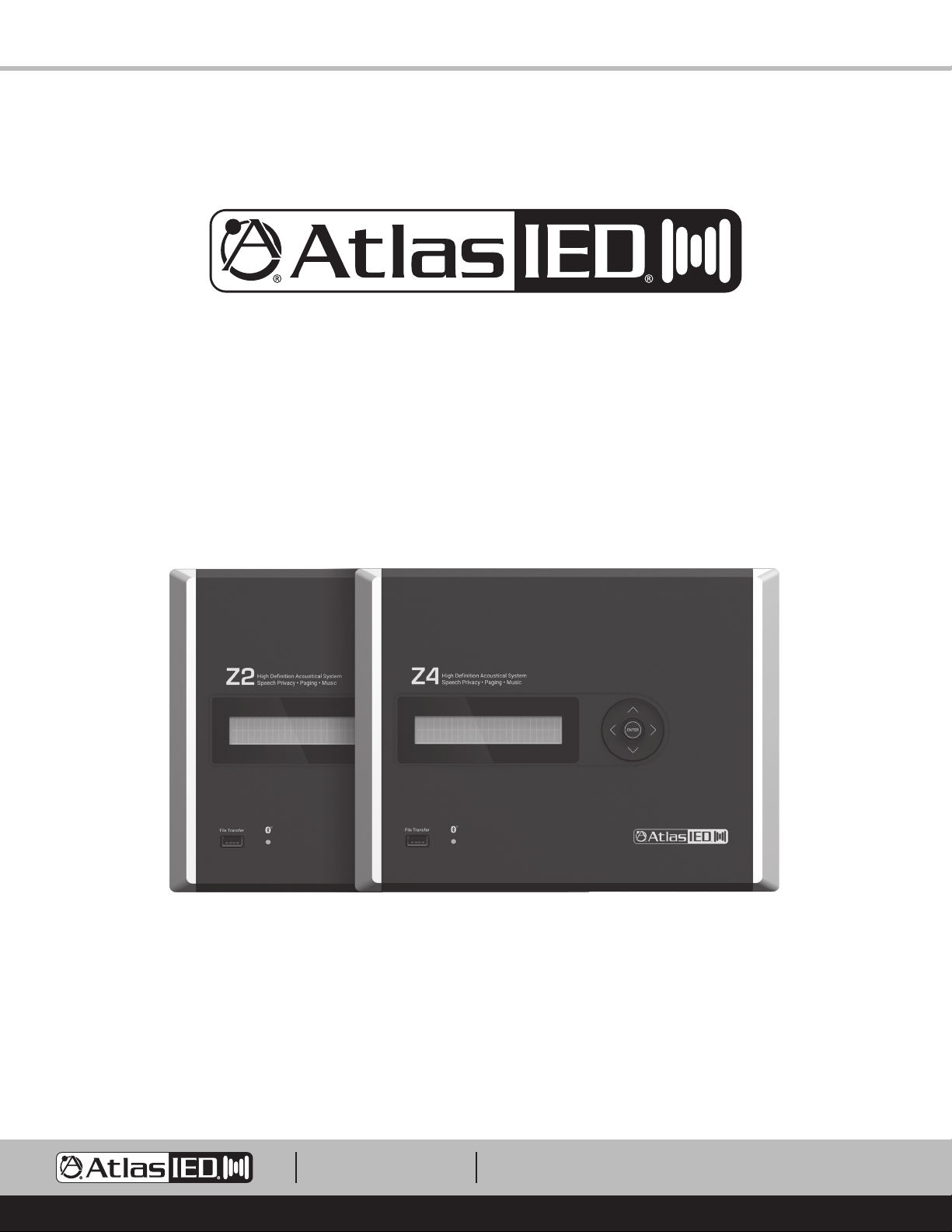
Z Series
High Definition Acoustical System
1601 JACK MCKAY BLVD.
ENNIS, TEXAS 75119 U.S.A.
TELEPHONE: (800) 876-3333
[email protected]
– 1 –
AtlasIED.com
Page 2
Z Series
Owner’s Manual
Table of Contents
Introduction ........................................................................................................................................................................................................... 3
Key Features .......................................................................................................................................................................................................... 3
Applications ............................................................................................................................................................................................................ 3
Package Contents ................................................................................................................................................................................................... 4
Opening the Z Series ............................................................................................................................................................................................. 5
Mounting the Z Series ............................................................................................................................................................................................ 5
Wiring the Z Series I/O Backbox ............................................................................................................................................................................ 9
• Mic / Line Balanced Input
• 3.5mm AUX Input
• Speech Enhancement Control Port
• Fault Control Port
• Speaker Terminals
Z Series Front Panel, Menu Display, and Navigation Controls ..............................................................................................................................10
Navigation Menu Tree ............................................................................................................................................................................................11
Understanding Unique Menu Tree Features ......................................................................................................................................................... 13
Default Ship Mode, Factory Presets, and SHS EQ .............................................................................................................................................. 14
Creating Custom Project Files .............................................................................................................................................................................. 15
Optional Accessories ............................................................................................................................................................................................ 16
• Z-SIGN - Wireless Enhanced Speech Privacy Activation Switch & Visual Indicator
• Z Series App - Enhanced Speech Privacy Activation Switch & System Tuning
• ASP-MG2240S - Wired Enhanced Speech Privacy Visual Indicator
• WPD-SWCC - Wired Enhanced Speech Privacy Activation Switch
Updating the Firmware ..........................................................................................................................................................................................17
Turning On the Z Series ....................................................................................................................................................................................... 18
®
Streaming Audio and Bluetooth
Specifications ....................................................................................................................................................................................................... 19
Dimensional Drawings ......................................................................................................................................................................................... 22
FCC Compliance ................................................................................................................................................................................................... 23
Warranty ............................................................................................................................................................................................................... 24
Paring ............................................................................................................................................................... 18
1601 JACK MCKAY BLVD.
ENNIS, TEXAS 75119 U.S.A.
TELEPHONE: (800) 876-3333
[email protected]
– 2 –
AtlasIED.com
Page 3
Z Series
Owner’s Manual
Introduction
The Z Series is a multi-zone speech privacy system that also supports background music and paging applications. Model Z2-B is a two-zone speech
privacy system providing 40-watts of total amplification and model Z4-B is four-zone speech privacy system delivering up to 80-watts of amplification.
The Z Series is an all-in-one solution that not only supplies high quality speech privacy, but also can deliver high quality background music and paging.
Mic / line and music inputs each have a five-band equalizer and Hi and Lo pass filters to assure maximum performance. Music inputs incorporate either
analog stereo summed inputs or Bluetooth
tailored to the vocal frequency range. Output limiters are in the audio chain to protect against system overdrive.
Advanced features of the Z Series include separate analog masking generators per zone, 14-day system commissioning ramp per zone, and PC project
design software allows system custom project files to meet installation needs.
For conference room applications where secure speech privacy is required, the Z Series features a Speech Privacy Enhancement mode that can be
engaged while a meeting is in progress. Enhanced Privacy mode applies additional acoustical energy to the surrounding environment, increasing the
privacy levels for the conference room occupants. These unique secured speech filters have been approved and implemented in many installations
around the world including military and government facilities. Activation of the Speech Privacy Enhancement feature is accomplished via hardwired
switch, an iOS
visual aid to notify attendees when Enhanced Privacy Mode is active.
®
or Android® application, or using an optional wireless desktop / wall mount switch. An optional wired or wireless sign is available for a
Key Features
• Includes Internal, High Efficiency 70.7V Transformer (Cannot be Bypassed for 8Ω Operation)
• Amplified Masking Controller
• 2 Speech Privacy Zones (Model Z2-B)
• 4 Speech Privacy Zones (Model Z4-B)
• 20-Watt 70V Output per Zone
• Out of Box Operational, Featuring AtlasIED Custom Presets
• Enhanced Privacy Mode with Wired and Wireless Signs Available
• Selectable Mic / Line Input for Paging or Recorded Messaging
• 3.5mm Stereo Summed Auxiliary Input for Background Music
• Bluetooth® Streaming for Background Music
• PC Software to Create and Save Custom Project Files
• System Commissioning Ramp on Each Zone
• iOS® and Android® App for System Tuning and Control
• Wireless Speech Enhancement Activation Switch and Sign
®
streaming. For paging applications, the Z Series incorporates a unique hi-Q feedback filter specifically
Applications
AtlasIED has been developing, manufacturing, assisting and commissioning sound masking systems for over forty years using proprietary Chanaud
masking filters. The Z Series includes a multitude of features enabling it to conform to most design requirements but remains intuitive enough for
simple operation and quick installation. The Z Series is designed to be aesthetically pleasing for office or conference room applications seamlessly
blending in to a variety of decors. Z Series placement is flexible allowing for mounting on a surface, in the wall, or in an equipment rack. The Z2-B
model delivers quality audio and speech privacy in spaces up to 7000 sq ft with two-zones of control flexibility. The Z4-B model features four-zones of
audio with total potential sound masking coverage of up to 14,000 sq ft. This compact integrated solution features out of the box selectable system
configuration presets that are accessible through the front panel display and navigation keys. The combination of these features makes for a simple but
effective speech privacy and audio control solution.
1601 JACK MCKAY BLVD.
ENNIS, TEXAS 75119 U.S.A.
TELEPHONE: (800) 876-3333
[email protected]
AtlasIED.com
– 3 –
Page 4
Z Series
Owner’s Manual
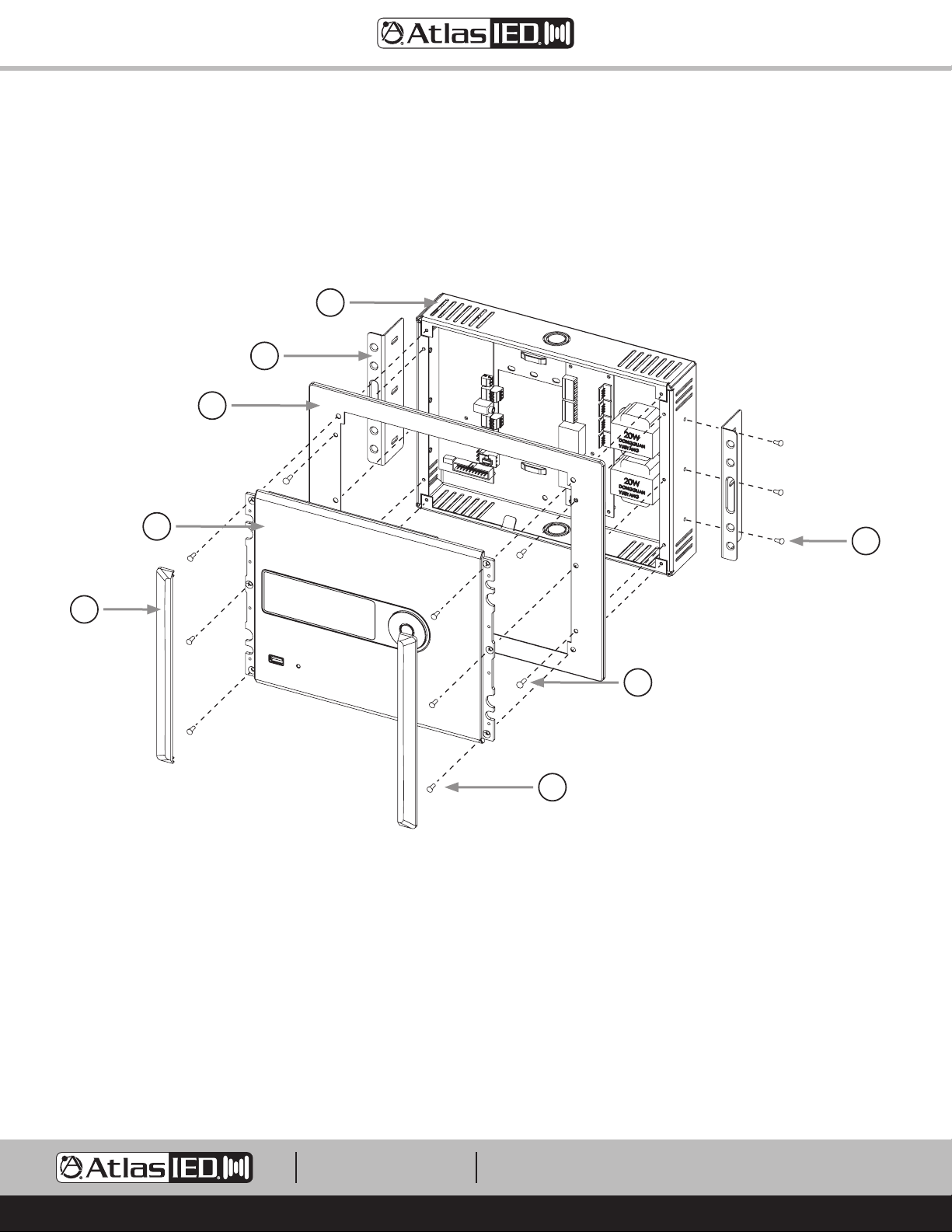
Package Contents
• Z2 or Z4 Unit, Qty 1
• External 100V – 240V to 24DCV UL Power Supply, Qty 1. Z2 = 2.5A, Z4 = 5.0A
• Input Connectors and Speaker Connectors
• Z Series Installation Sheet
F
G
D
A
B
A. Control Panel
B. Control Panel Dress End Caps
C. Control Panel Mounting Screws M3 x 10mm, Qty 6
D. Dress Ring
E. Dress Ring Screws M3 x 5.7mm, Qty 4
F. I/O Backbox
G. In-Wall Support Brackets, Qty 2
H. In-Wall Support Bracket Screws M3 x 5.7mm, Qty 6
H
E
C
Fig 1
1601 JACK MCKAY BLVD.
ENNIS, TEXAS 75119 U.S.A.
TELEPHONE: (800) 876-3333
[email protected]
– 4 –
AtlasIED.com
Page 5
Z Series
Owner’s Manual
Opening the Z Series
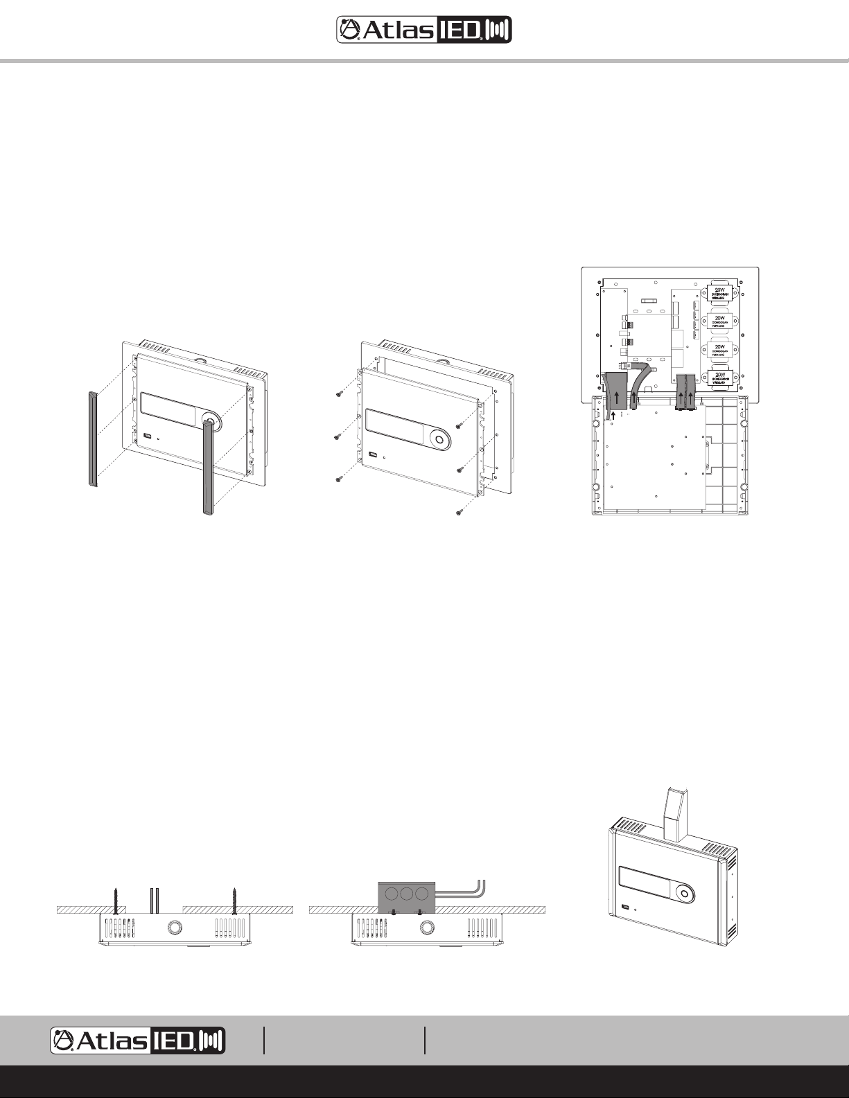
1. Remove the two Control Panel Dress End Caps. These End Caps are held by magnets with guide pins for alignment. They need to be lifted away
from the panel. See Figure 2.
2. Remove the six Control Panel mounting screws.
3. Carefully tilt back the Control Panel to access the I/O Backbox. The Control Panel and I/O Backbox are connected via harness as seen in Figure 4.
Note: Remove the harness connectors from the Control Panel and leave the cables connected to the I/O Backbox.
Fig 2
Fig 3 Fig 4
Mounting the Z Series
The Z Series can be surface mounted, in-wall flush mounted, or rack mounted. Before mounting the Z Series, there are several factors to take into
consideration. Select the best area for wiring infrastructure such as speaker wire, AC mains power, paging cable and background audio source cables.
Placement of the Z Series is also critical when using the Bluetooth® audio streaming feature. The Z Series should be placed within 50ft of the paired
audio source. Powering the Z Series requires use of the included external power supply. It is suggested to place the Z Series within 6ft of a 120V AC
outlet. If this is not possible, the power supply wire for the 24VDC output can be extended up to 50ft. Note: This does not void the warranty as it is
the low voltage wire that is being extended. Note: Pay attention to the DCV polarity when reconnecting the removable Phoenix connector.
Wire Routing
The I/O Backbox wall mounting can be secured by applying screws to a surface, in-wall, or to a 2-gang electrical box. Wiring into the Z Series can be
done via rear 2-gang opening of the I/O Backbox or via electrical conduit
For wiring the Inputs and Outputs see “Wiring the Z Series I/O Backbox”.
3
/4" and 1/2". Knockouts are located on the top and bottom of the I/O Backbox.
Wire Entering From Rear Wire Entering Electrical Box Wire Entering Top Conduit
1601 JACK MCKAY BLVD.
ENNIS, TEXAS 75119 U.S.A.
TELEPHONE: (800) 876-3333
[email protected]
AtlasIED.com
– 5 –
Page 6
Z Series
Owner’s Manual
Surface Mount - Direct to Wall
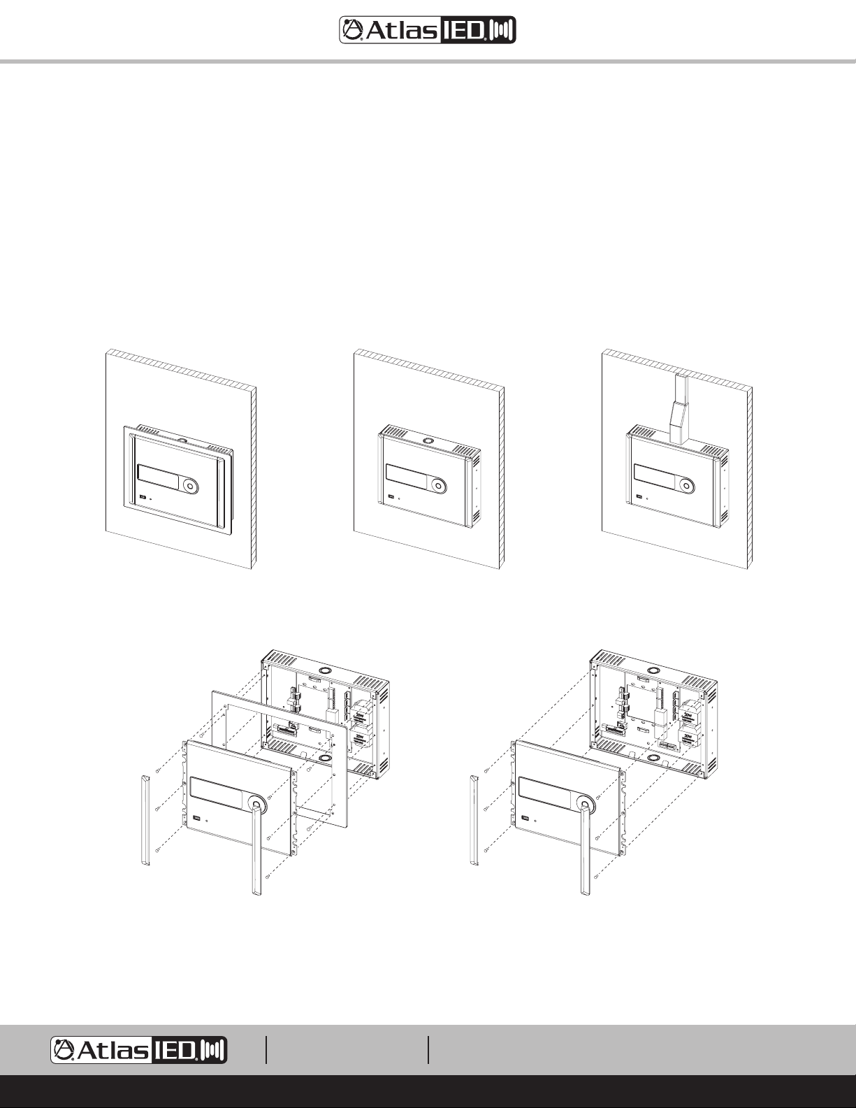
1. Determine the use of the Dress Ring and the wiring routing options. Note: The I/O Backbox Dress Ring and Side Support brackets can be left
assembled or they can be removed.
2. Remove the front Control Panel from the I/O Backbox. The Dress Ring can be left on if preferred. Be careful removing the cables from the Control
Panel PCB.
3. Secure the I/O Backbox to the wall or electrical box.
4. Wire the I/O Backbox. See “Wiring the Z Series I/O Backbox” for details.
5. After the I/O Backbox is wired, re-install the front panel (carefully plug in cable connectors, fold closed, and fasten 6 screws) and apply the two
magnetic end caps. Note: Do not force close or damage may occur. Realign the wires if necessary for smooth panel closure.
Surface Mount
with Dress Ring
Assembly View with Dress Ring
Surface Mount
Surface Mount
without Dress Ring
Surface Mount
without Dress Ring, Top Conduit Wired
Surface Mount
Assembly View without Dress Ring
1601 JACK MCKAY BLVD.
ENNIS, TEXAS 75119 U.S.A.
TELEPHONE: (800) 876-3333
[email protected]
– 6 –
AtlasIED.com
Page 7
Z Series
Owner’s Manual
In-Wall Mount
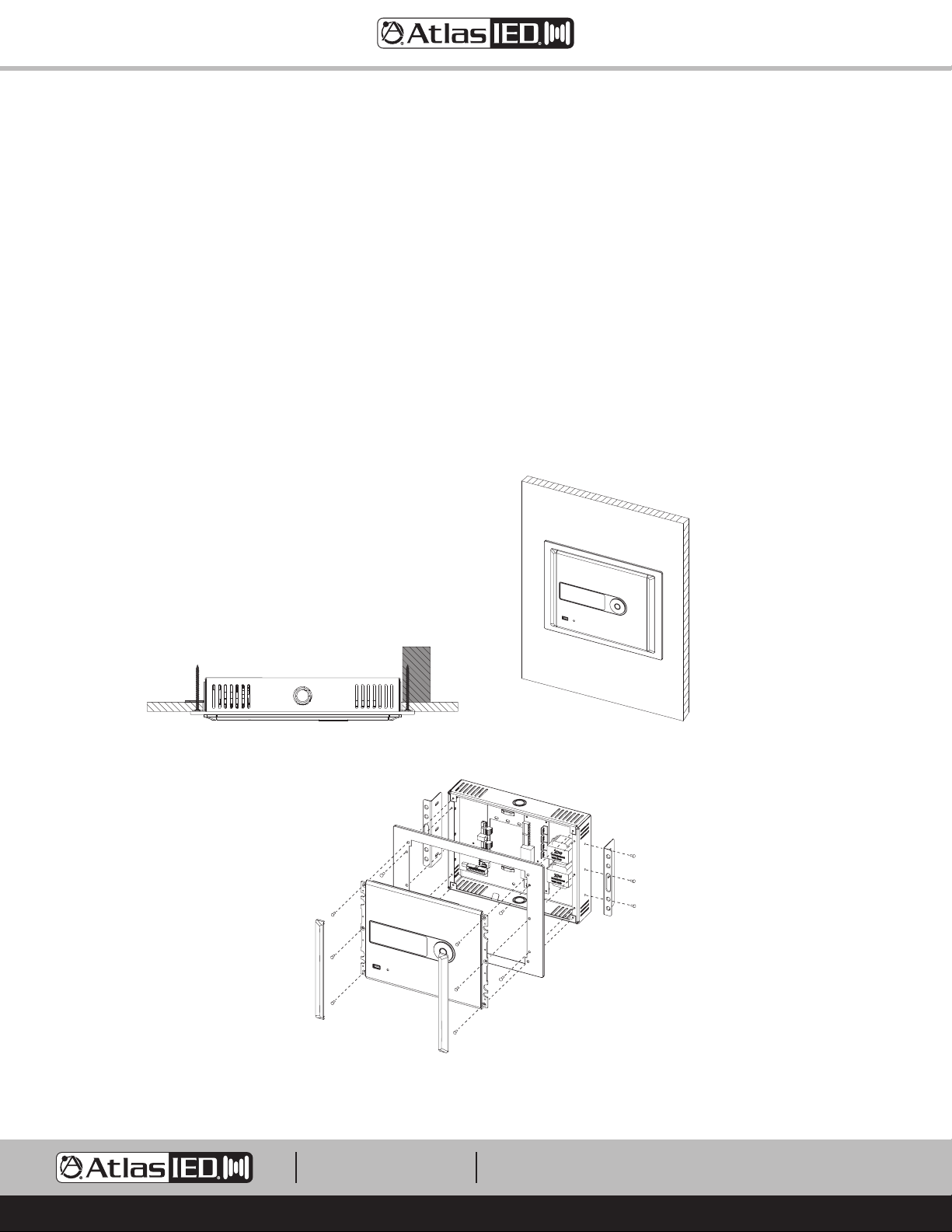
1. Cut a hole in the wall (8.27"H x 10.83" W). Make sure the hole has at least 2" of rear clearance. Note: Aligning one side over a stud is the easiest
and most secure method. See Figure 13.
2. Remove the front Control Panel from the I/O Backbox. Be careful removing the cables from the Control Panel PCB.
3. Remove the Dress Ring from the I/O Backbox to allow access to the side mounted wall mount brackets.
4. Temporarily fit the Z Series into the wall cut-out and adjust the side brackets so the front of the I/O Backbox sits flush to the finished wall.
5. On the opposite side of the stud, use an EZ Anchor or add a small backing block (wood) to screw into. Note: The center of the wall mount bracket
has an opening large enough to allow a drywall screw to hold the wood backing block in place while mounting.
6. After mounting in-wall, re-fasten the Dress Ring to the front of the I/O Backbox.
7. Wire the I/O Backbox. See “Wiring the Z Series I/O Backbox” for details.
8. After the I/O Backbox is wired, re-install the front panel (carefully plug in cable connectors, fold closed, and fasten 6 screws) and apply the two
magnetic end caps. Note: Do not force closed or damage may occur. Realign the wires if necessary for smooth panel closure.
In-Wall Mount
Assembly View with Dress Ring
1601 JACK MCKAY BLVD.
ENNIS, TEXAS 75119 U.S.A.
Fig 14Fig 13
TELEPHONE: (800) 876-3333
[email protected]
AtlasIED.com
– 7 –
Page 8
Z Series
Owner’s Manual
Rack Mount
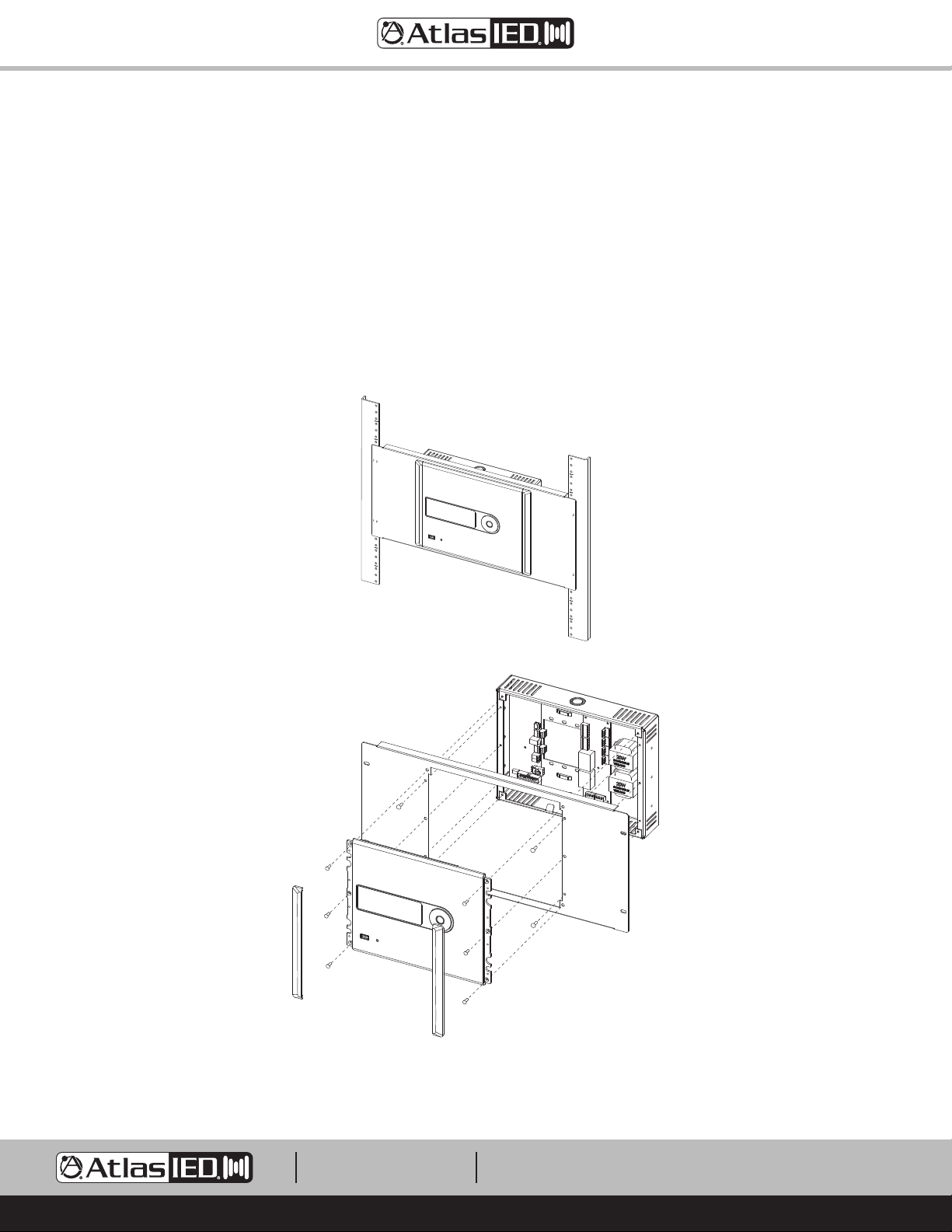
1. The Rack Mount Kit is not supplied with the Z Series. The ZSERIES-RMK can be ordered at atlasied.com.
2. Remove the front Control Panel from the I/O Backbox. Be careful removing the cables from the Control Panel PCB.
3. Remove the Dress Ring and the two side mounted wall mount brackets from the I/O Backbox. The Rack Mount Plate replaces the Dress Ring.
4. Install the Rack Mount Plate onto the I/O Backbox using the same screws and screw locations used with the Dress Ring.
5. Mount the rack panel into a 19" rack.
6. Wire the I/O Backbox. See “Wiring the Z Series I/O Backbox” for details.
7. After the I/O Backbox is wired, re-install the front panel (carefully plug in cable connectors, fold closed, and fasten 6 screws) and apply the two
magnetic end caps. Note: Do not force closed or damage may occur. Realign the wires if necessary for smooth panel closure.
Fig 16
Rack Mount
Assembly View
1601 JACK MCKAY BLVD.
ENNIS, TEXAS 75119 U.S.A.
TELEPHONE: (800) 876-3333
[email protected]
– 8 –
AtlasIED.com
Page 9
Z Series
Owner’s Manual
Wiring the Z Series I/O Backbox
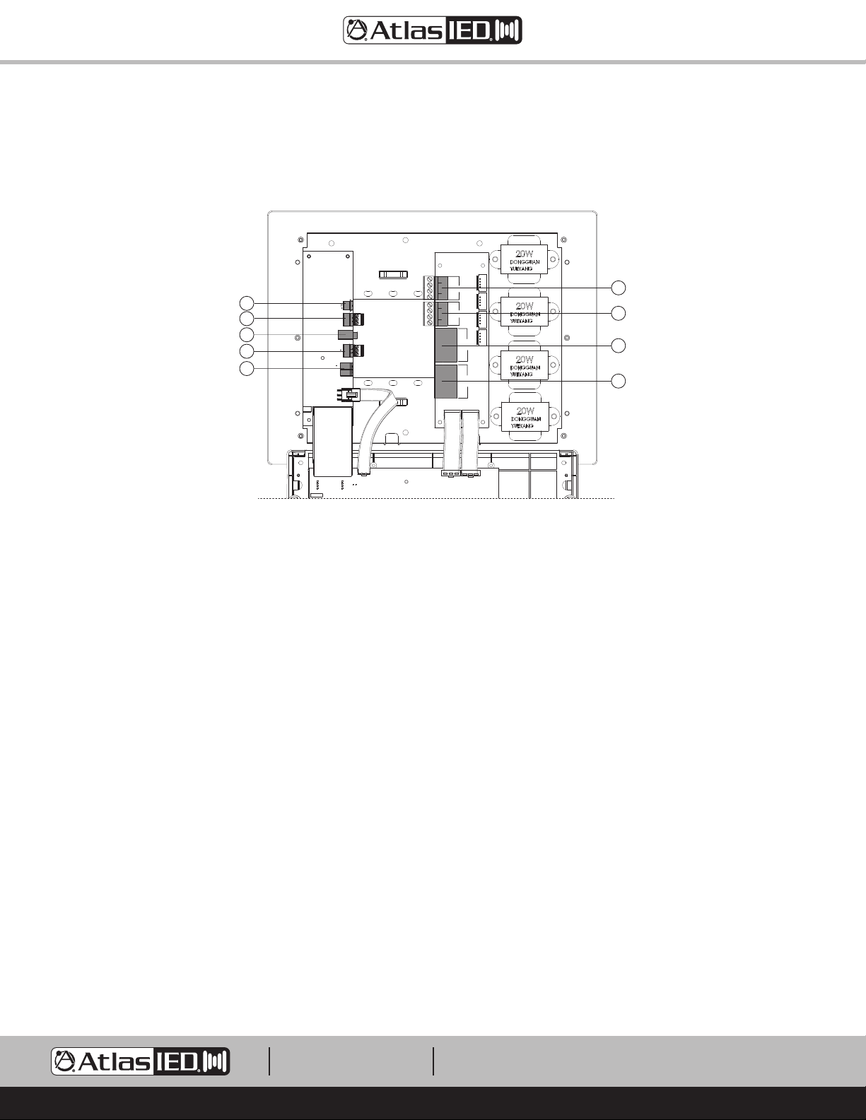
Before wiring the I/O Backbox, decide on the installation application required for the Z Series. There are a variety of application guides available at
atlasied.com. This guide covers the Input and Output connections. Refer to Figure 18 for a visual aid.
MODEL: Z2/Z4-Power
REV:1.3
Fault
E
F
G
H
I
Normally
Closed
Privacy
+10V
GND
Engage
Aux Input
Mic/Line Input
+
GND
Power 24VDC
+
MODEL: Z2/Z4-AMP OUT
REV:1.3
Z4
-
Z4
+
Zone 3&4
Speaker
Out
Z3
-
Z3
+
Z2
-
Z2
+
Zone 1&2
Speaker
Out
Z1
-
Z1
+
A
Zone 3&4
Speaker Out
RJ45 A&B
In Parallel
B
A
Zone 1&2
Speaker Out
RJ45 A&B
In Parallel
B
Z1 Z1 Z2 Z2Z3 Z3 Z4 Z4
+ - + - + - + -
T4
T3
T2
T1
B
A
C
D
Fig 18
A. Zone 1 & 2 Euro Block Speaker Terminals - Connect 70V speakers to this 5.08mm pitch Euro Block terminal. Pay attention to the Zone and the
speaker polarity.
B. Zone 3 & 4 Euro Block Speaker Terminals (Z4 Only) - Connect 70V speakers to this 5.08mm pitch Euro Block terminal. Pay attention to the Zone
and the speaker polarity.
C. These terminals will be used for future products. Do not use.
D. These terminals will be used for future products. Do not use.
E. Fault Reporting Port - This 2 position 3.5mm pitch Euro Block terminal is a relay that is normally closed during normal operation and opens when
the Z Series has a fault condition that requires service.
F. Speech Privacy Enhancement Control Port - This control port is used to remotely activate the Privacy Enhancement feature and to power the
optional wired “Enhanced Privacy In Use” sign. When the “G” & “Engage” are shorted together a series of events happens.
• The front panel display will read “Enhanced Privacy”.
• The Masking Level will change to the user preset Privacy level. Factory default is +6dB. This can be changed in the navigation menu.
• The port named “To LED” will supply a +10V DCV 100mA voltage to power a indicator sign.
Note: See the application guide on how to use the Privacy Enhancement feature.
G. AUX 3.5mm (Music) Input - This receptacle accepts a 3.5mm stereo plug. The Left and Right inputs are actively stereo summed to form a mono
signal. This signal can be routed to any Zone via the front panel navigation controls. The Input sensitivity can be adjusted via the navigation controls
from 316mV – 1V. Factory default is 775mV.
H. Mic / Line (Paging) Input - This 3-position 3.5mm Euro Block connecter is for Balanced Line or Mic level sources. Mic or Line, Gain and Phantom
power can be selected in the Paging section of the navigation controls menu. Unbalanced line inputs can be inserted with proper wire
configuration by connecting the (G) and (-) terminals together.
I. DC Power Input - The Z2 comes with a global 24VDC 2.5A external power supply. The Z4 comes with a global 24VDC 5A external power supply.
The power supply is equipped with a 2-position 5.08mm connector that mates to this DC Power input socket.
1601 JACK MCKAY BLVD.
ENNIS, TEXAS 75119 U.S.A.
TELEPHONE: (800) 876-3333
[email protected]
– 9 –
AtlasIED.com
Page 10
Z Series
Owner’s Manual
Z Series Front Panel, Menu Display and Navigation Controls
F
E
C
D
B
A
Fig 20
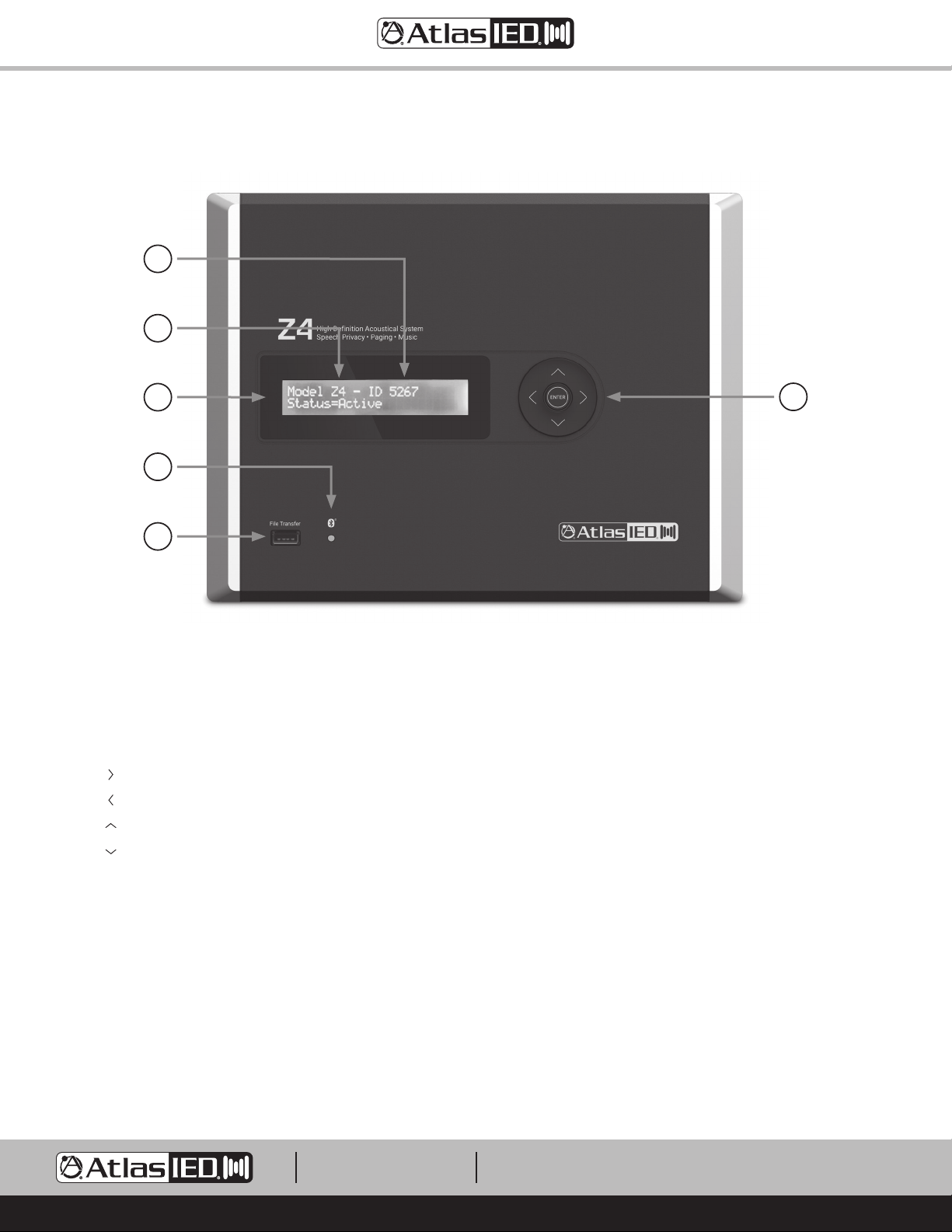
A. USB File Transfer Port - The port is used for uploading or downloading a project file. It is also used for updating firmware. To update the firmware
refer to the “Updating the Firmware” section.
®
B. Bluetooth
C. Display Menu
D. Navigation Keys
• ( ) = Navigate Right direction in the menu
• ( ) = Navigate Left direction in the menu
• ( ) = Navigate Up direction in the menu
• ( ) = Navigate Down direction in the menu
• (Enter) = Power On / Off and Save command
E. Model Number
F. Unit ID Number - This number is unique to each specific unit. It is used to identify the unit if there are more than one of same model types within
the range of the App or Wireless “Enhanced Privacy In Use”. The App will list all devices within range of the BLE
the device you want the App to connect to.
Streaming Music Status Indicator
®
or UHF and will help to identify
1601 JACK MCKAY BLVD.
ENNIS, TEXAS 75119 U.S.A.
TELEPHONE: (800) 876-3333
[email protected]
– 10 –
AtlasIED.com
Page 11
Z Series
Owner’s Manual
Navigation Menu Tree
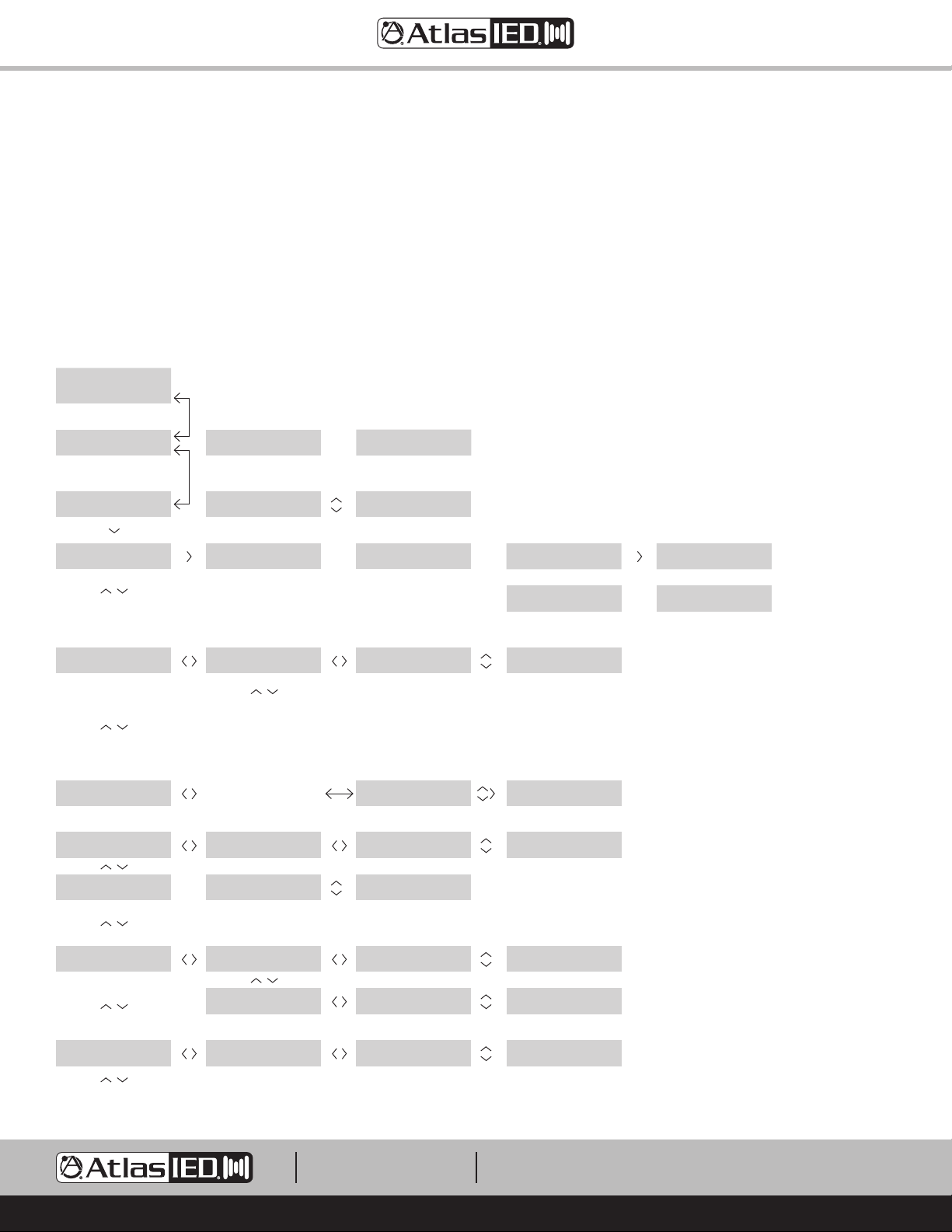
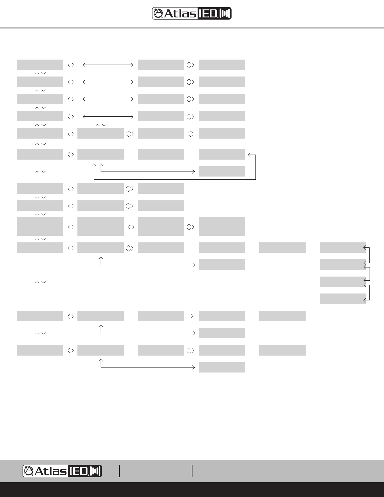
The Z Series menu tree allows access to settings for making adjustments to the Speech Privacy and Sound system. The menu tree is divided into two
sections, User Control Settings and Advanced Settings. Note: The Advanced Settings can be password protected if needed.
• Zones 3 and 4 apply to the Z4 only
• Volume Adjust - 0 = Max level, -40 = Mute
• An asterisk “*” appears in the upper left of the window for each step to the right of the home menu
Press up / down to change selection. Press enter to confirm / save. Press left to go back. Press right-left to move cursor.
From any sub-home menu, hold the Up arrow for 6 seconds to return to boot up Home Screen.
(Off - Blank Screen)
To turn ON, press and hold
Enter for 3 sec
AtlasIED Model - Z4
Booting Up……
Model Z4 - ID XXXX
Status = Active
Bluetooth Music
Pair >
“Mute” blinks while muted;
>> again unmutes
Music Volume
Adjust > or Mute >>
Advanced Settings
Enter PW >
Master Volume
Adjust > or Mute >>
E
Default=Yes ; press Enter to
Power off
To Power Off ? Yes or No
Select Up/Dn/Enter
Press Up/Dn selects No,
Enter for Options
To Power Off ? Yes or No
Select Up/Dn/Enter
Pairing……
“Mute” blinks while muted;
>> again unmutes
*Zone 1 Music Volume = -10
Adjust > or Mute >>
Repeat Steps for Zone 2,3,4
Note: Zone 3 & 4 = Z4 Only
Requires PW past this point
Default = 0000
*Master Volume = -10
Zone 1 Adjust > or Mute >>
(Off - Blank Screen)
E
Press Up/Dn selects options
Exit or Reset to Default
settings -Enter to execute
*Selections:Exit -Reset
E
Select Up/Dn/Enter
Pairing Successful
Screen
Change
RED characters show the
setting that changes with
UP/DN keys
**Music Volume = Mute-0
Set Zone 1 Up/Dn/Enter
Mute= -40 to 0 at top of
fader - match software
GUI scale
PW-blinking character up/dn
to select X number (0000
default); Right to next
character; Enter to Save
Password 0000
Up/Dn/Rt Select/ Enter
Enter PW to go to Advanced
Settings
**Master Volume = Mute-0
Zone 1 Up/Dn/Enter
Replaces Home Screen
while streaming
iPhone Streaming
Screen
Change
Press > to Disconnect BT
or
Pairing Fail
after 30 sec back to Home
*Zone 1 Music Volume = -10
E
Adjust > or Mute >>
returns to home after 1 min
Change Password
E
Enter PW >
After PW returns to home
after 2 min with no changes
*Master Volume = -10
E
Zone 1 Adjust > or Mute >>
Disconnect goes to Home
Screen
iPhone Streaming
Enter to Disconnect BT
Model Z4 - ID XXXX
Screen
Change
Status=Active Menu-Up/Dn
Project-FacDefaultV1.2
Change >
Masking + Privacy Volume
Adjust > or Mute >>
PAGE Volume
Adjust > or Mute >>
FacDefaultV1.2
Change Up/Dn/Enter
Up/Dn scrolls thru the list
of presets, Enter saves and
loads project
*Masking Volume = -10
Zone 1 Adjust > or Mute >>
*Privacy Level = +6dB
Zone 1 Adjust >
Repeat Steps for Zone 2,3,4
Note: Zone 3 & 4 = Z4 Only
*PAGE Volume = -10
Zone 1 Adjust > or Mute >>
Repeat Steps for Zone 2,3,4
Note: Zone 3 & 4 = Z4 Only
Project-FacDefaultV1.2
E
Change >
Enter to Save and return to
view Active Project (position
#10 is reserved for Custom
Project Uploads)
**Masking Volume = Mute-0
Zone 1 Up/Dn/Enter
**Privacy Volume = +6dB
Zone 1 Up/Dn/Enter
**PAGE Volume = Mute-0
Zone 1 Up/Dn/Enter
1601 JACK MCKAY BLVD.
ENNIS, TEXAS 75119 U.S.A.
*Masking Volume = -10
E
Zone 1 Adjust > or Mute >>
*Privacy Level = +6dB
E
Zone 1 Adjust >
*PAGE Volume = -10
E
Zone 1 Adjust > or Mute >>
TELEPHONE: (800) 876-3333
[email protected]
– 11 –
AtlasIED.com
Page 12
Mic + Phantom
Set Mic or Line >
*Mic / Line: MIC
Phantom: ON
Z Series
Owner’s Manual
Mic + Phantom
E
Set Mic or Line >
Mic Feedback Filter
Set >
BT/Aux Input Sensitivity
Set >
SHS EQ
Set/Change >
Change Password
Enter PW >
Pair Z Signs
0 Paired - Pair Signs >
Date=2018-11-07
Set/Change >
Clock=Sun 16:05
Set/Change >
SYS Commissioning Ramp
Set >
Firmware V1.XX
Update >
Password Settings 0000
Up/Dn/Rt Select/ Enter
Repeat Steps for Zone 2,3,4
Note: Zone 3 & 4 = Z4 Only
*To Pair Sign
Press Enter
*Year Month Day
2018 11 07
*Day Time 24hr
Wed 18:35 Up/Dn/Rt/Enter
*SCR=Z1-Off Z2-Off
Set > Z3-14 Z4-14
*Insert USB with Firmware
and Press Enter to Load
*Mic Feedback Filter: ON
Frequency: 200Hz
*Input Sensitivity = 775mv
Adjust Up/Dn/Enter
Paging: OFF
Music: OFF
Password Settings 0000
E
Up/Dn/Rt Select/ Enter
E
Date=2018-11-07
E
Set/Change >
Clock=Sun 16:05
E
Set/Change >
**Zone 1=OFF >
Zone 2=OFF >
Zone 3=ON >
Zone 4=ON >
Loading Firmware...
E
Pairing...
Mic Feedback Filter
E
Set >
BT/Aux Input Sensitivity
E
Set >
Paging: ON / OFF
E
Music: ON / OFF
Change Password
E
Enter PW >
Pairing Successful
Screen
Change
or - after 20 seconds
Pairing Fail
SYS Commissioning Ramp
Set >
E
USB Found
Screen
Change
Press Enter to Upload
or
No Found
Please Check USB
E
Searching...
Screen
Change
File Found!
Screen Change
FW Updating...
Screen Change
Upgrade Successful!
Screen Change
AtlasIED Model -Z4
Booting Up...
Back Up Current
Configuration Settings >
Upload from USB
Configuration Settings >
*Please Insert USB
*Please Insert USB
Ready to Back Up File
Screen
Change
Press Enter to Back Up
Ready to Upload File
Screen
Change
Press Enter to Upload
(File Location = #10) or
1601 JACK MCKAY BLVD.
ENNIS, TEXAS 75119 U.S.A.
Back Up Successful
E
or
Back Up Fail
Please Check USB
Upload Successful
E
Name of File Loaded
Upload Fail
Please Check USB
TELEPHONE: (800) 876-3333
[email protected]
– 12 –
Back Up Current
Screen
Change
Configuration Settings >
Upload from USB
Screen
Change
Configuration Settings >
AtlasIED.com
Page 13
Z Series
Owner’s Manual
Understanding Unique Menu Tree Features
Masking & Privacy Volume Adjust - Each Zone has its own Masking and Speech Privacy Enhancement adjustments. These are separate adjustments
but are relative to each other.
1. Masking Level Zone 1 - This adjusts the Level of Sound Masking only in Zone 1. Note: This adjustment is Pre or Before the Master Zone Level 1.
2. Privacy Level - This feature is designed to temporarily change the masking level. This feature is ideal to use in a medical
office, conference room, or any area that needs a more secure speech environment to prevent conversations from being overheard. When
engaged, the Level at Zone 1 output will increase by the Privacy level entered. In most cases 6dB is common. This Privacy fader level is “relative”
to the Zone fader level and is not active regardless of the position of the fader until the Speech Privacy Enhancement ports “G” and “Engage”
are shorted together or the Z-SIGN or App activate it. Refer to their specific manuals for details. Note: The Privacy Enhancement does not change
the Music (BT / AUX) or Paging (Mic / Line levels). We recommend following the Privacy Enhancement examples listed on the web site to
understand the masking signal flow and gain structure.
Mic & Phantom Adjust (Mic or Line Gain Select) - In this section the Balanced input can be configured to be at Mic or Line Level. If Mic mode is
selected you can also turn on the Phantom 24vDC power if required.
Mic Feedback Filter Adjust - If the Balanced input is selected to Mic mode and you are experiencing feedback while paging, the Z2 / Z4 has a
specialized filter to reduce or eliminate the feedback. Navigate to On / Off, select On, then adjust the frequency Up or Down until the feedback is gone.
This notch filter frequency adjustment range is 200Hz to 6KHz with the level being fixed at -20dB cut with a Q14 (0.1 BW)
System Commissioning Ramp (SCR) - Each Zone has it is own SCR On / Off function and they operate independently from each other. When
turned on, the SCR function last for 14 days with each day representing 1dB of change. When the SCR is turned On, the display will show number 14
representing the numbers of SCR days left. The Masking Level will be down -14dB from the set Masking Level. Note: The SCR is a count down timer
that displays the number of days left. When it gets to 0 days, the SCR will automatically turn Off. At this point the Masking level is where the Masking
fader is set to. The clock must be set for the SCR to function.
Example: If the Masking A Level is -10dB and you select 14 Days for the ramping to take place, then turn ON the SCR, the Masking A Level is -24dB.
The next day the SCR changes to 13 Days and the Masking A output level increases by 1dB making the Masking level -23dB. This will continue until
the SCR days reach 0 Days and the Masking A level reaches -10dB. The SCR will turn OFF automatically.
1601 JACK MCKAY BLVD.
ENNIS, TEXAS 75119 U.S.A.
TELEPHONE: (800) 876-3333
[email protected]
– 13 –
AtlasIED.com
Page 14
Z Series
Owner’s Manual
Default Ship Mode, Factory Presets, and SHS EQ
The Z Series can store 10 different programs that are called Presets. The Z Series is shipped with the Factory Preset active. This preset is designed to
be used in many general applications. For a detailed list of functions of the other presets visit atlasied.com. Note: Presets are subject to change, refer
to atlasied.com for up to date information and detailed application guides.
Factory Default Mode
FacDefaultV1.2 - Good general masking curve applicable to situations where
grids. Note: Zones 3 and 4 apply to the Z4 only.
• Master Levels for Zones 1, 2, 3, 4 are set to -10 (Level adjustment range is 0 to -40 with 0 being the maximin level).
• Masking Levels for Zones 1, 2, 3, 4 are set to -20.
• Enhance Privacy Level is set to +6dB. Refer to Enhanced Privacy Mode for details on this feature.
• Masking EQ is fixed with a general EQ curve to meet many open and above ceiling masking applications. In many installations all that is needed is
level adjustment.
• Paging Set to (Line) Input and the Paging Levels for Zones 1, 2, 3, 4 are set to -10.
• Music Levels for Zones 1, 2, 3, 4 are set to -10. Note: Music Levels apply to both Bluetooth® Streaming and AUX 3.5mm input.
• Music Input Sensitivity is set to 775mV.
Other Presets Shipped with the Z Series
Note: The level settings for the Presets listed below are the same as the Factory Default Preset.
• M1000V1.3 - Use with the M1000 in above ceiling (plenum) masking.
• M1000ROpClngV1.3 - Use with the M1000R-W in open ceilings with no grid.
• UnderFLRV1.2 - Use with the M1000 or M2000-LP for under floor masking applications. A 2W tap required.
• FAP33TABV1.2 - Use in direct field, down firing masking using the FAP33T-W. Wiring of the 2 masking channels must be in an A/B configuration,
consult factory for details.
• FAP40TABV1.2 - Use in direct field, down firing masking using the FAP40T. Wiring of the 2 masking channels must be in an A/B configuration, consult
factory for details.
• FAPSHSABV1.3 - Use in direct field, down firing masking using the SHS-6T2. Wiring of the 2 masking channels must be in an A/B configuration, consult
factory for details.
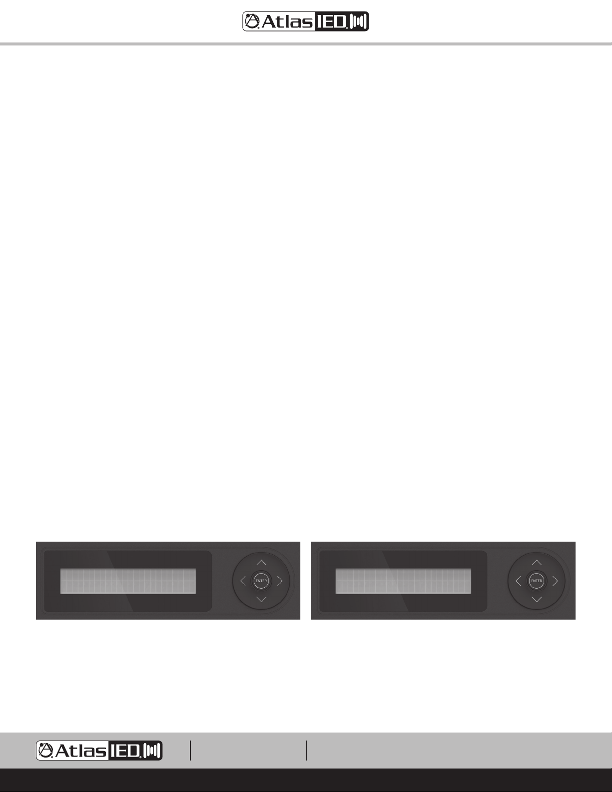
SHS EQ
Some speakers require unique EQ processing to maximize their performance. This does not mean the speaker will not function without the specific
EQ settings. When using an SHS speaker with a Z2 / Z4 for background audio or paging applications, use the custom EQ setting. AtlasIED has made a
simple SHS EQ On or Off setting for Paging or Music. This setting is located in the navigation tree. When On, this SHS EQ will be applied to all zones.
The Music & Paging EQ are still available for room tuning.
Note: This feature only works with firmware v1.64 or higher and software v1.10 or higher.
1
/3 octave tuning will not be done. Use in Open ceilings and above ceiling
SHS EQ
Set/Change >
1601 JACK MCKAY BLVD.
ENNIS, TEXAS 75119 U.S.A.
Paging: OFF
Music: OFF
Navigate to Paging and Music and select On or OffNavigate in the menu tree to SHS EQ and select Enter.
TELEPHONE: (800) 876-3333
[email protected]
– 14 –
AtlasIED.com
Page 15
Z Series
Owner’s Manual
Creating Custom Project Files
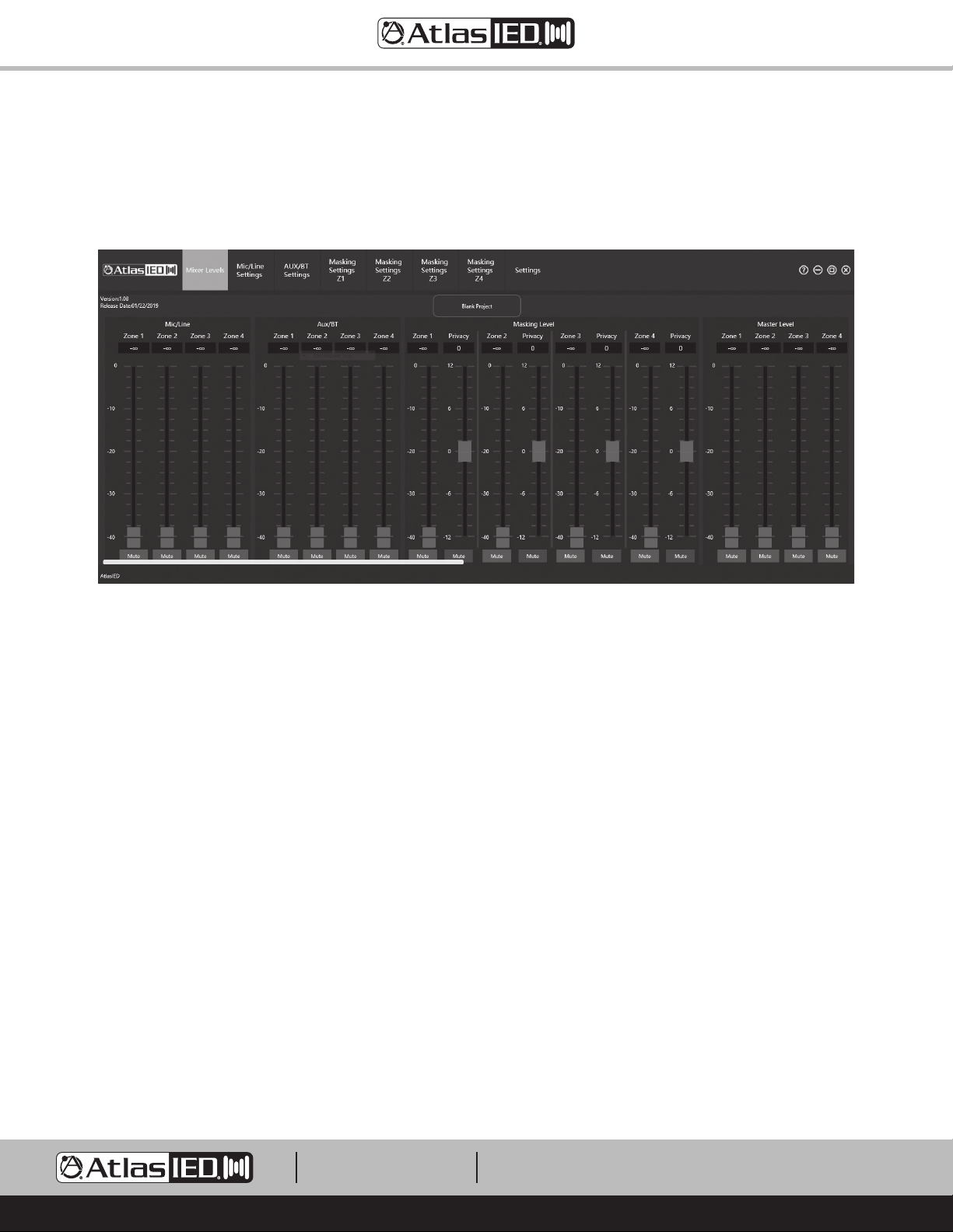
Custom project files can be created by using the Z Series PC design software. This software can be downloaded at atlasied.com. Files can be custom
created or modified to meet your application’s needs. Note: There is separate software for the Z2 and Z4 units. Refer to the Z2 / Z4 Preset Design
software guide for software operation.
Fig 19
Creating a Project File on the PC and Uploading to the Z Series
1. Create a design in the Z2 or Z4 PC software. Note: There is separate software for each model.
2. Save it to a location on the computer.
3. Save the project file to a USB drive. Note: The file needs to be in the root directory. Only one project file with the extention .Z2HDM or .Z4HDM
can be in the USB root directory for the Z Series to load successfully.
4. Insert the USB drive into the Z Series USB File Transfer Port located on the front panel. Navigate through the menu tree and upload it into the
Z2 or Z4. Note: When uploaded, this file automatically becomes the active file.
5. Z Series file preset locations 1-9 have to be loaded via firmware update.
Creating a Project File in the Z Series, Saving it to a Drive, and Uploading it into the Software
1. Modify a design in the Z2 or Z4 PC software. Note: There is separate software for each model.
2. Insert a USB drive into the Z Series.
3. Navigate through the Z Series menu to save a file.
4. Save the file to a USB drive. Note: The Z Series will automatically create a Project Folder on the USB for projects the first time you save a project.
5. Load it into the PC. Upload the file into Z2 or Z4 software. Modify as needed.
6. Save the file to the PC. Place the project file onto the root directory of an external USB drive and upload to the Z Series. Only one project file with
the extention .Z2HDM or .Z4HDM can be in the USB root directory for the Z Series to load successfully.
1601 JACK MCKAY BLVD.
ENNIS, TEXAS 75119 U.S.A.
TELEPHONE: (800) 876-3333
[email protected]
– 15 –
AtlasIED.com
Page 16
Z Series Optional Accessories
Note: All series accessories can be used together.
Z Series
Owner’s Manual
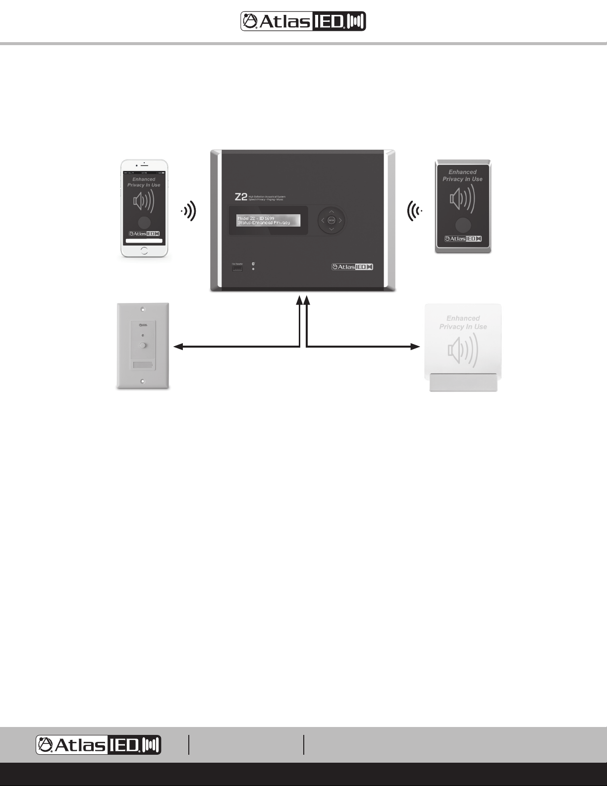
Mobile App to Control
Enhanced Privacy Activation
Start
Settings
®
Z Series iOS
A. ASP-MG2240S - The Enhanced Privacy In Use Wired Sign is used to inform the public that a Sound Masking system is in use for their security
while having a private conversation. This wired privacy sign is designed to be integrated with the Z Series. The ASP-MG2240S is a 10V DC voltage
powered Acrylic LED Diffusion type sign featuring a multi-functional mount with a polished aluminum finish. The ASP-MG2240S can be mounted to
a wall or to a single gang electrical box. The mounting hardware is included to support most installation requirements.
B. WPD-SWCC - A décor style wall plate featuring a push button switch that activates/deactivates a hard latch contact closure. This product is
designed to be used with compatible AtlasIED products that are designed to be remotely activated. The unit is constructed of durable ABS material
and includes a red LED system status indicator as well as a removable label guard for easy and clean designation of switch function. The unit has a
four-conductor interface connection designed to work with the included Phoenix style connector. This unit can function in remote activation
scenarios up to 200 feet from the controlled unit using 22-gauge wire.
C. Z-SIGN - The AtlasIED Z-SIGN Enhanced Privacy Sign is used to inform the public that a Sound Masking system is in use for their security while
having a private conversation. This wireless privacy sign is designed to be integrated with the AtlasIED Z Series High Definition Acoustical
Systems. The Z Series sign works in conjunction with models Z2-B & Z4-B base units. The Z-SIGN is a wireless transceiver that can be used to
activate the System’s Enhanced Speech Privacy Mode and illuminate indicating the room is secure. The Z-SIGN utilizes 915MHz wireless
technology for communication to the Z2 & Z4 base units. This technology assures communication from the sign to the base unit through walls and
up to 100ft apart. The Z-SIGN also utilizes BLE
allows for the customer to engage Speech Privacy Enhancement, plus it allows for the installer to adjust the zone levels remotely during system
setup. If using an App, the Z Series features an Enhanced Speech Privacy switch to allow for the sign to set on a desk. The Z-SIGN utilizes high
quality rechargeable batteries to assure maximum usage between charges. The Z-SIGN can also be powered utilizing the included power supply.
Refer to the Z-SIGN data sheet for more information.
or Android® App
Wired Activation
WPD-SWCC
®
technology for the Z-SIGN to communicate to a phone or tablet via iOS® or Android® App. This App
Wireless Enhanced Privacy
Activation Sign
Z-SIGN
Wired Sign
ASP-MG2240S
1601 JACK MCKAY BLVD.
ENNIS, TEXAS 75119 U.S.A.
TELEPHONE: (800) 876-3333
[email protected]
– 16 –
AtlasIED.com
Page 17
Z Series
Owner’s Manual
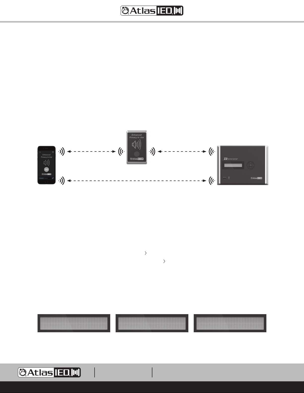
D. Z Series App for iOS® or Android® - The Z Series App can be used to engage the Z2 or Z4 into the Enhanced Speech Privacy Mode. It can also be
used to remotely adjust music, paging and masking levels per zone. Each input can be tuned to meet each zone’s acoustical requirements.
Note: The level and tuning section of the Z Series App is password protected.
®
• The App uses the smartphone Bluetooth
around 100 ft line of site. To avoid dropouts, it is recommended to be in the same room as the Z2 / Z4 base units and stay within 50ft.
• If longer distance is required a Z-SIGN can be used to act as a relay-bridge between the phone App and the Z2 / Z4 base units. The phone
connects to the Z-SIGN via Bluetooth
The UHF allows for much greater transmission distances compared to Bluetooth®. It is common to get command transmission distances over
100 ft but will vary depending on the building construction and number of walls it has to go through.
BLE® technology to connect to the Z2 / Z4 Base unit. The distance of the Bluetooth® transmission is
®
BLE® and the Z-SIGN transmits the commands to and from the Z2 / Z4 Base units via UHF frequency.
Z-SIGN
Z Series App
Bluetooth
Under 50'
®
BLE
®
UHF
100' or More
Bluetooth® BLE
®
Z2 or Z4 Base Unit
Under 50'
Updating the Firmware
1. Compare the firmware loaded on the device to the latest firmware on the AtlasIED web site.
2. If there is a newer firmware available, download the firmware from https://www.AtlasIED.com/Z4-b (or Z2-b)
3. Example: The file will be a compressed folder and look like this: Z4_Series_V1_48.bin (do not Extract it)
4. Save any custom project settings to a USB drive before updating the firmware. Refer to the “Creating Custom Projects Files” section for detailed
instructions.
5. In the Menu Tree, navigate down to the Firmware page and press ( )
6. Insert the USB drive with new Z2 or Z4 FW on the Root directory and press ( ) to update. Follow the prompts:
7. After pressing Enter, the screen will say “searching”; “FW Updating…”; “Successful”; then “Booting….”
8. After the FW update is complete, the Z2 or Z4 will return to the Home Screen. Remove the USB drive.
9. Navigate to the “Clock and Date” Menu and enter the current date and time.
10. To upload a saved Project File, navigate to the “Upload from USB” Menu and follow the prompts. The uploaded file will become the active project.
11. Navigate to the “Pair Z Signs” Menu and re-pair any Z-SIGNs.
Firmware v1.46
Update >
Step 5 Step 6 Step 7
Insert USB with Firmware
and Press Enter to Load
1601 JACK MCKAY BLVD.
ENNIS, TEXAS 75119 U.S.A.
TELEPHONE: (800) 876-3333
[email protected]
– 17 –
USB Found
Press Enter to Upload
AtlasIED.com
Page 18
Z Series
Owner’s Manual
Turning on the Z Series
Press and hold (3 sec) Enter on the Navigation control button and the unit will boot up. Don’t be alarmed if you are hearing masking present at the
speakers. The Masking Level is set low to allow walking the area to see if all the speakers are functioning. Levels can be adjusted via the Navigation
controls. From here select a different preset and change functions. Note: Settings are automatically saved when powering off or if there is a Power
Failure.
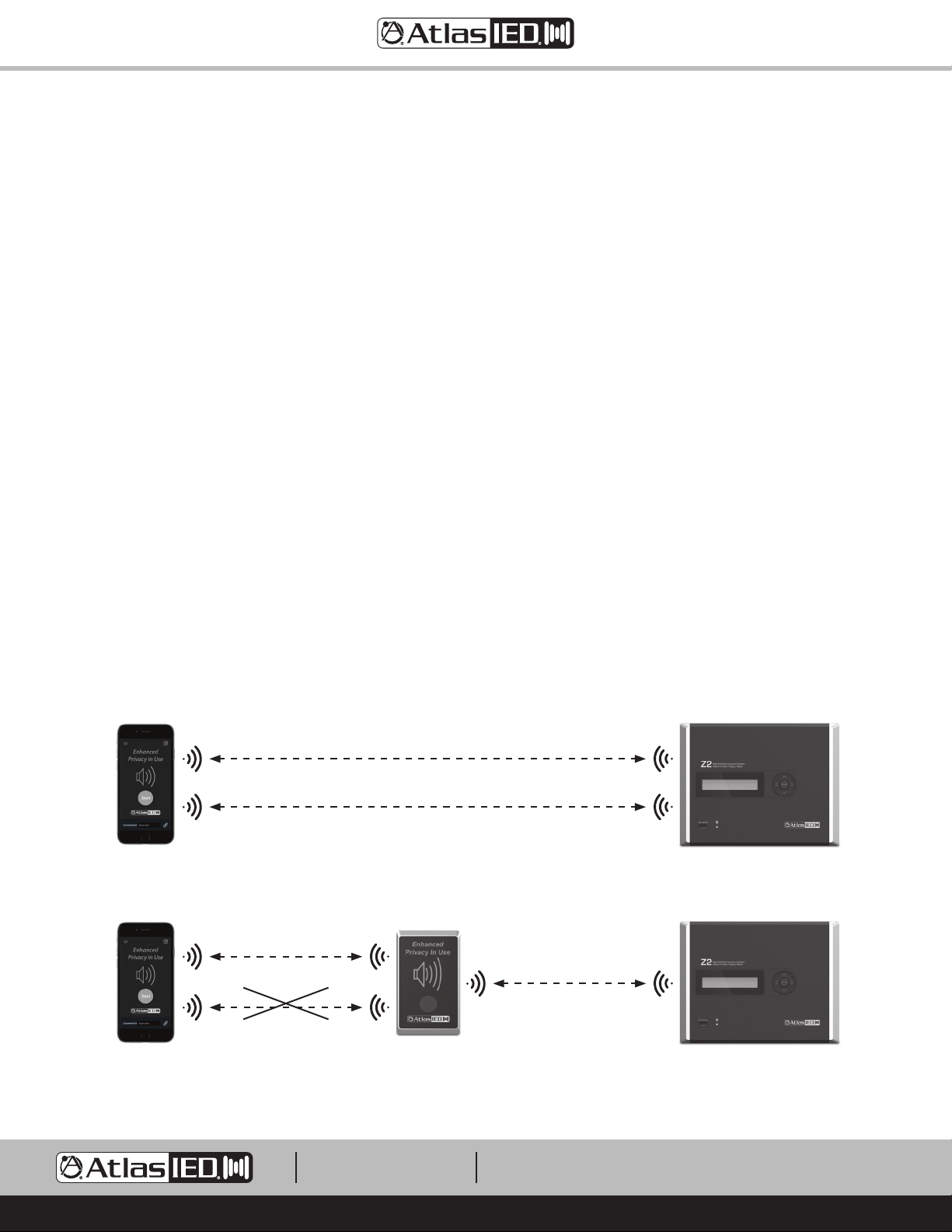
Streaming Audio and Bluetooth® Paring
Streaming music from an audio device using Bluetooth® is a convenient way to run background audio without having wires in the way. However, there
are limitations to Bluetooth® technology. Bluetooth® operates best when the audio device and the Z Series base unit are close to each other. Line of
sight is always best. Bluetooth® can go through a wall as long as the audio device and base unit are very close to each other, but this practice is not
recommended. Note: Bluetooth® streaming music can only be connected to Z Series base unit. See diagram below.
Pairing an Audio Device to the Z Series
®
A. Make sure Bluetooth
B. On the Z Series Home screen the model and identification code of the unit will appear. Remember this because it will appear in the audio device
Bluetooth
C. For illustration purposes we are pairing to a Model Z4 with an ID of 5267. On the Z4, navigate to the Bluetooth
arrow and the window will change to “Pairing...”. Find AtlasIED Z4-5267 on the Bluetooth® discovery section of the audio device. Select it to
connect. Note: Each time a new Z Series unit is used, the audio device will have to be paired to the specific Z Series unit. Use the Model Number
and Unit ID Number of the Z Series unit to determine which unit to pair with.
D. Remember the audio level of the music from the Z Series works in conjunction with the Bluetooth
E. The Z Series Home screen will display the name of the audio device on the display while streaming. The audio device can also be disconnected
from the Home screen.
®
list while pairing.
is active on the audio device. Make sure the Bluetooth® Device and discovery page is open.
®
Music screen. Select the Right
®
level setting in the audio device.
Z Series App Z2 or Z4 Base Unit
Bluetooth® BLE
Bluetooth® Streaming
Z Series App Z-SIGN Z2 or Z4 Base Unit
Bluetooth® BLE
Bluetooth® Streaming
®
®
UHF
1601 JACK MCKAY BLVD.
ENNIS, TEXAS 75119 U.S.A.
TELEPHONE: (800) 876-3333
[email protected]
– 18 –
AtlasIED.com
Page 19
Z Series
Owner’s Manual
System Z2-B Z4-B
Type 40-Watt 2-Zone High Definition Acoustical System 80-Watt 4-Zone High Definition Acoustical System
Power Supply Type 24VDC (2.5A) External Power Supply 24VDC (5A) External Power Supply
Independent Analog Noise Generators 2 4
Independent Zones for Indirect Field Masking,
Paging or Background Audio
Independent Zones for Direct Field Masking 1 2
Output Power (Note 1)
70V per Zone 20-Watts
Factory Default Settings (As Shipped)
Amplifier Configuration 2 Zone (Indirect Field Masking) 4 Zone (Indirect Field Masking)
Level Controls Assignment Masking Level, Mic / Line, AUX & Bluetooth
I/O Matrix Mic / Line, AUX, Bluetooth
Master Levels Set to -10dB
Level Settings
Masking Zone DSP Settings
Music Input DSP Settings
Paging Input DSP Settings
GPIO Control Ports (Rear Panel) Enhanced Speech Privacy Engage, Privacy Sign Output, Fault
Inputs
Input Quantity Speech Privacy Engage, Privacy Sign Output, Fault
Input Type (Line Balanced or Unbalanced)
Input Impedance 40kΩ
Input Sensitivity
Maximum Input Level Vrms Mic 50mV, Line 2V, AUX 2V
Input Connectors Type Mic / Line 3.5mm Euro Block, AUX 3.5mm TRS, Bluetooth
Level Control
Front Panel Navigation Keys Masking Zones 1-4, Paging (Mic / Line), Music, Master Zones 1-4
App Control Masking Zones 1-4, Paging (Mic / Line), Music, Master Zones 1-4
Status Indicators
Power Front Panel Display
Input Signal No
Output Signal No
Output Fault Front Panel Display
®
Bluetooth
Front Panel Features
Power Switch Navigation Enter Button (Press and hold for 3 seconds)
Display 2x 24 Segment, Blue Illumination
USB USB Standard
Music Front Panel LED (Blue)
Masking Set to -20dBU
Mic / Line Set to Mic -10dBu
Aux 3.5mm & Bluetooth® Sensitivity Set to .775mV, Level -10dB TBD, Muted
Zones 1-4 Configured the Same, Masking EQ – Set to Preset #1 Factory Default File 1.xx
Open Ceiling Curve, Level -20dB, Privacy Level +6dB
Input Sensitivity HPF 120Hz, LPF 15kHz, EQ 5 Bands = 0dBU, Limiter = 0dB, Zone Levels -10dB, Paging Mute
Receive OFF
Mic Mode, Phantom Off, VOX Music AUX / BT Mute Setting Off, Paging Feedback Filter Off,
HPF 120Hz, LPF 15KHz, EQ 5 Bands = 0dB, Limiter = 0dB, Zone Levels -10
Mic / Balanced Line selectable, 3 Position Phx 3.5mm pitch.
AUX 3.5mm L & R Summed Unbalanced, Bluetooth
(Note: Bluetooth
Mic 10mV
Line 1V
Music (Bluetooth
®
and AUX 3.5mm Share the same Level control & EQ)
®
& AUX 3.5mm) Selectable, 1V, 775mv, 500mV, 316mV
2 4
®
Adjustable via Front Panel Navigation
®
Routed to Zone 1-2 or 1-4
®
®
1601 JACK MCKAY BLVD.
ENNIS, TEXAS 75119 U.S.A.
TELEPHONE: (800) 876-3333
[email protected]
– 19 –
AtlasIED.com
Page 20
Z Series
Owner’s Manual
Internal Panel Features
Power Input 24V DC, Z4 = 5A , Z2 = 2.5A, 2 Position, 5.08mm Euro Block, (Phoenix)
AUX Input 3.5mm TRS Jack
Paging (Mic / Line) 3 Position, 3.5mm Euro Block, (Phoenix)
Fault GPIO Contact Closure (NC), Opens upon power failure or fault, 2 position Euro block, 3.5mm
Privacy Engage 3 Position, 3.5mm Euro Block, (Phoenix), 10VDC Out, GND, Activation ports
Zone 1-4 Amplifier Outputs (Direct Field Masking) 4 RJ45
Zone 1-4 Amplifier Outputs (Indirect Field Masking) 2 Position, 5.08mm Euro Block, (Phoenix)
DSP Features and Elements
®
Level Control Paging (Mic / Line), Music (AUX & Bluetooth
System Commissioning Ramp Separate Commissioning Ramps for Each Masking Zone Output, Duration Settings 1 -14 Day Selection Made in
Masking Noise Pink and White Noise Analog Generators
Presets
Hi and Low Pass Filters Paging (Mic / Line), Music (AUX / BT), Masking Zone 1,2,3,4, 12db Butterworth, Variable Frequency, Enable / Disable
EQ Music (AUX / BT) - 5 Filters (Q1.4, 1.0 BW) +/-12dB, SHS Filter
Delay N/A
Limiter Music (AUX / BT), Paging (Mic / Line), Threshold 0db to -15dB
DSP Type 24-Bit
Interface Control Ports
USB USB for Fat32 Formatted USB Drive
Wireless Sign Connectivity 915MHz with BLE
Bluetooth
GPIO Ports
Location Internal
GPIO Ports Qty 2 Functions
Connection
Functions
Amplifier Zone Output Terminals (Direct Field Masking)
Output Connectors Type RJ45
Number of Terminals Qty 4 RJ45 (32 Pins)
Output Connectors Fixed or Removable Fixed
Wire Type Required CATe 5,6
Amplifier Zone Output Terminals (Indirect Field Masking)
Output Connectors Type 5.08mm Euro Block, (Phoenix)
Number of Terminals Z2-B: 4 (2 Amplifier Channels), Z4-B: 8 (4 Amplifier Channels)
Output Connectors Fixed or Removable Removable
Wire Size 14 AWG
Terminal Spacing 5.08mm
Current Rating 12A per Terminal
Wire Class Required Class 2
®
Enhanced Privacy Level Masking Zone 1,2,3,4
Preset Software, Front Panel On / Off Selection per Zone,
7 Day Battery Clock Back Up
10 Total, Factory Presets Note: Subject to change. Custom Presets can be Created in Z Series Software and
Uploaded via USB Port
Button
Paging (Mic / Line) - 5 Filters (Q3.25, 0.44 BW), Feedback Filter (Frequency Range 200Hz - 6kHz, Q14,0.10 BW) -20dB
Masking Per Zone - 20 Filters (Q4.3, 0.33 BW, 1/3 Octave)
®
Control
Bluetooth® version 4.1
1. Speech Privacy Enhancement - Euro Block PHX Type 3.5mm, 3 Pins, Ground, +10VDC
(Output After Engaged), C1
2. Fault Reporting – Euro Block PHX Type 3.5mm, 2 Pins Contact Closure (NC) (Open for power failure
or amp Channel fault)
1. Speech Privacy Engage & Privacy Sign Output
2. Fault Reporting
), Masking Zone 1,2,3,4, Master Level Zone 1,2,3,4
1601 JACK MCKAY BLVD.
ENNIS, TEXAS 75119 U.S.A.
TELEPHONE: (800) 876-3333
[email protected]
– 20 –
AtlasIED.com
Page 21
Z Series
Owner’s Manual
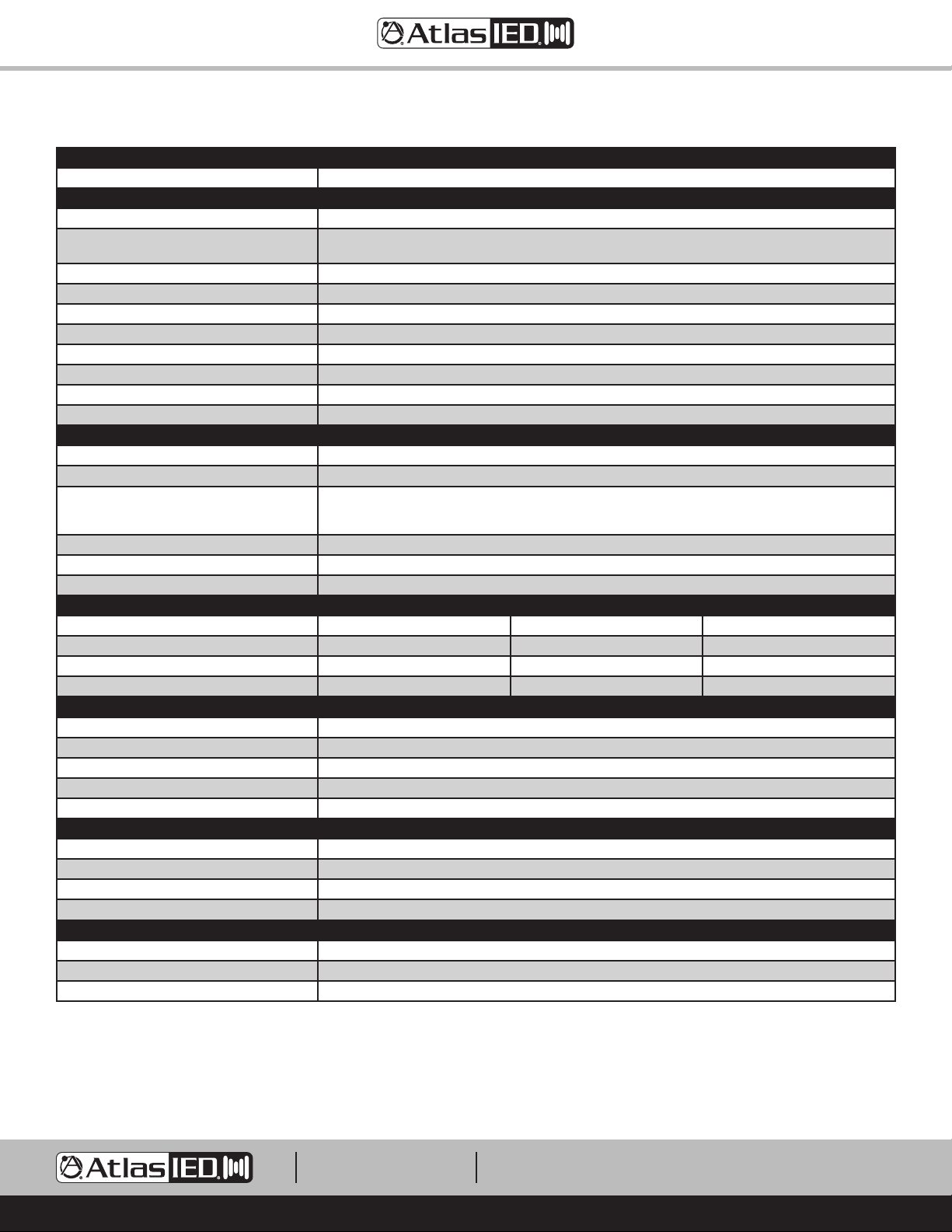
Cooling
Convection Ye s
Electrical Specifications (General)
Masking Generator One Per Amplifier Channel
Total Harmonic Distortion 1kHz and 1dB Below
Rated Power
Frequency Response 50Hz - 15kHz (DSP Filters Set to Flat)
Signal to Noise Ratio >90dB Below Rated Output (A-weighted)
Damping Factor (20Hz to 400Hz) N/A
Slew Rate N/A
Crosstalk 69dB @ 1kHz
Protection Hi / Low Input Voltage, Thermal, Short, Over Current
Max Output Peak Voltage 100V (Meets Class 2 Low Voltage Wire Codes)
File Storage Recall or Save to Device, Recall or Save to USB Drive
AC Power Requirements
Operating Voltage External Supply 110V-230V, 50/60Hz
Mains Interface IEC C7 Receptacle to Inline Power Supply, To Amp - 24V DC Output 2 Position, 5.08mm Euro Block, (Phoenix)
Power Cord (Included) 1.2m, NEMA 1-15P Standard USA 2 Pin Plug to IEC C7 Receptacle with 18/2
Minimum Power-Up Voltage 100 V
Maximum Operating Voltage 240V
Recommended AC Mains Current Requirements 10A
Power Consumption and Current Draw (Note 4) Amps Z2/Z4 Watts Z2/Z4 BTU Z2/Z4
Standby / APD Mode N/A N/A N/A
Idle Active / On 120mA / 160mA 6.7W / 10.2W 22.6 BTU / 34.8 BTU
Average Power, All Channels Driven (Note 2) 280mA / 560mA 21W / 40W 71 BTU / 136 BTU
Max Power, All Channels Driven (Note 3) 1A / 1.9A 73W / 140W 250 BTU / 477 BTU
Dimensions and Weight
Rack Mount Requirements 5RU, 19" ZSERIES-RMK
Dimensions - Unit (without Dress Ring) W 10.7" x H 8.17" x D 2.32" (272mm x 208mm x 59mm)
Dimensions - Shipping W 14" x H 13.5" x D 5" (356mm x 343mm x 127mm)
Weight - Unit Z2 - 7.7lb (2.8kg), Z4 - 10lb (3.77kg)
Weight - Shipping Z2 - 10.7lb (4.2kg), Z4 - 13lb (5.17kg) (Preliminary)
Agency Approvals
North America Agency UL, TUV, GMA (Power Supply)
FCC Class B (Conducted & Radiated Emissions) Part 15 of the FCC Rules
RoHS / WEEE Compliant Ye s
CE Yes, Power Supply
Optional Accessories
ASP-MG2240S Wired Enhanced Speech Privacy Sign
Z-SIGN Wireless Enhanced Speech Privacy Sign
ZSERIES-RMK 5RU Rack Mount Kit
Typical, 0.2%
SPT-2 Black
Rated up to 7A 125V to 240V
NOTES:
1. Power level measurement is define as follows: 1KHz sine AUX, line or mic inputs.
2. Average Power is defined as Pink Noise input signal applied to achieve 1/4 of the power rating.
3. Max Power is defined as 1 KHz input signal applied to achieve the maximum power output before clipping into a specified load.
4. BTU is calculated by the AC Mains Power consumed minus the total power output measured at the specified load and condition, multiplied by 3.412.
Example: 785 Watts from the AC Source - 600 Watts Total Output power = 185 x 3.412 = 631 BTU
1601 JACK MCKAY BLVD.
ENNIS, TEXAS 75119 U.S.A.
TELEPHONE: (800) 876-3333
[email protected]
– 21 –
AtlasIED.com
Page 22
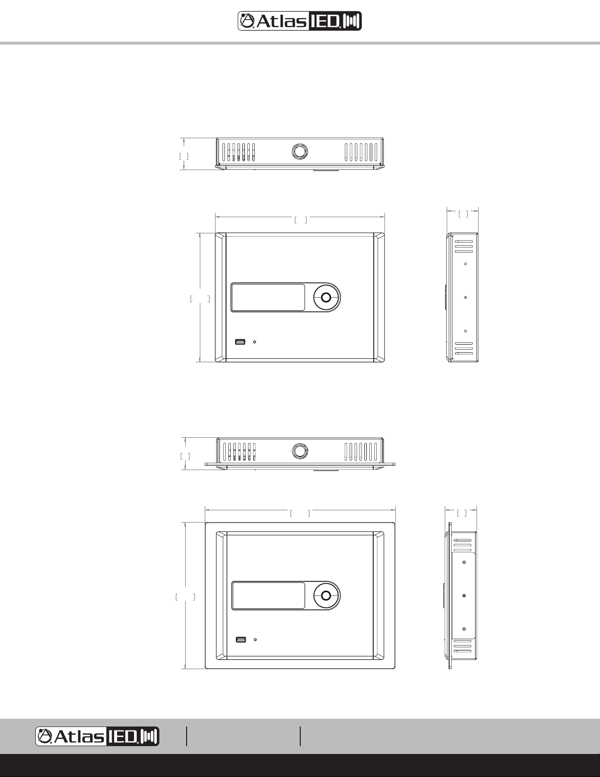
Dimensional Drawings
PRELIMINARY
PRELIMINARY
Surface Mount Configuration
2.32
59
207.50
8.17
Z Series
Owner’s Manual
Top
10.71
272
2.32
59
Flush Mount Configuration
237.50
2.32
9.35
Front
59
Top
12.15
308.50
Side
2.32
59
1601 JACK MCKAY BLVD.
ENNIS, TEXAS 75119 U.S.A.
Front
TELEPHONE: (800) 876-3333
[email protected]
– 22 –
Side
AtlasIED.com
Page 23
Z Series
Owner’s Manual
FCC Statement
1. This device complies with Part 15 of the FCC Rules. Operation is subject to the following two conditions:
(1) This device may not cause harmful interference, and
(2) This device must accept any interference received, including interference that may cause undesired operation.
2. Changes or modifications not expressly approved by the party responsible for compliance could void the user’s authority to operate the equipment.
Note: This equipment has been tested and found to comply with the limits for a Class B digital device, pursuant to Part 15 of the FCC Rules.
These limits are designed to provide reasonable protection against harmful interference in a residential installation. This equipment generates uses
and can radiate radio frequency energy and, if not installed and used in accordance with the instructions, may cause harmful interference to radio
communications. However, there is no guarantee that interference will not occur in a particular installation. If this equipment does cause harmful
interference to radio or television reception, which can be determined by turning the equipment off and on, the user is encouraged to try to correct the
interference by one or more of the following measures:
Reorient or relocate the receiving antenna.
Increase the separation between the equipment and receiver.
Connect the equipment into an outlet on a circuit different from that to which the receiver is connected.
Consult the dealer or an experienced radio/TV technician for help.
FCC Radiation Exposure Statement
This equipment complies with FCC radiation exposure limits set forth for an uncontrolled environment. This equipment should be installed and
operated with minimum distance 20cm between the radiator & your body
1601 JACK MCKAY BLVD.
ENNIS, TEXAS 75119 U.S.A.
TELEPHONE: (800) 876-3333
[email protected]
– 23 –
AtlasIED.com
Page 24

Limited Warranty
All products manufactured by AtlasIED are warranted to the original dealer/installer, industrial or commercial purchaser to be free from defects in
material and workmanship and to be in compliance with our published specifications, if any. This warranty shall extend from the date of purchase for
a period of three years on all AtlasIED products, including SOUNDOLIER brand, and ATLAS SOUND brand products except as follows: one year on
electronics and control systems; one year on replacement parts; and one year on Musician Series stands and related accessories. Additionally, fuses
and lamps carry no warranty. AtlasIED will solely at its discretion, replace at no charge or repair free of charge defective parts or products when the
product has been applied and used in accordance with our published operation and installation instructions. We will not be responsible for defects
caused by improper storage, misuse (including failure to provide reasonable and necessary maintenance), accident, abnormal atmospheres, water
immersion, lightning discharge, or malfunctions when products have been modified or operated in excess of rated power, altered, serviced or installed
in other than a workman like manner. The original sales invoice should be retained as evidence of purchase under the terms of this warranty. All
warranty returns must comply with our returns policy set forth below. When products returned to AtlasIED do not qualify for repair or replacement
under our warranty, repairs may be performed at prevailing costs for material and labor unless there is included with the returned product(s) a written
request for an estimate of repair costs before any nonwarranty work is performed. In the event of replacement or upon completion of repairs, return
shipment will be made with the transportation charges collect.
EXCEPT TO THE EXTENT THAT APPLICABLE LAW PREVENTS THE LIMITATION OF CONSEQUENTIAL DAMAGES FOR PERSONAL INJURY, ATLASIED
SHALL NOT BE LIABLE IN TORT OR CONTRACT FOR ANY DIRECT, CONSEQUENTIAL OR INCIDENTAL LOSS OR DAMAGE ARISING OUT OF THE
INSTALLATION, USE OR INABILITY TO USE THE PRODUCTS. THE ABOVE WARRANTY IS IN LIEU OF ALL OTHER WARRANTIES INCLUDING BUT
NOT LIMITED TO WARRANTIES OF MERCHANTABILITY AND FITNESS FOR A PARTICULAR PURPOSE.
AtlasIED does not assume, or does it authorize any other person to assume or extend on its behalf, any other warranty, obligation, or liability. This
warranty gives you specific legal rights and you may have other rights which vary from state to state.
Service
Should your Z Series High Definition Acoustical System require service, please contact the AtlasIED warranty department at
1-877-689-8055, ext. 277 or www.atlasied.com/support to obtain an RA number.
AtlasIED Tech Support can be reached at 1-800-876-3333 or www.atlasied.com/support.
Visit our website at www.AtlasIED.com to see other AtlasIED products.
©2019 Atlas Sound L.P. The Atlas “Circle A”, Soundolier, and Atlas Sound are trademarks of Atlas Sound L.P. IED is a registered trademark of Innovative Electronic Designs LLC. All Rights Reserved.
All other trademarks are the property of their respective owners. All specs are subject to change without notice. ATS005890 RevE 3/19
1601 JACK MCKAY BLVD.
ENNIS, TEXAS 75119 U.S.A.
TELEPHONE: (800) 876-3333
[email protected]
AtlasIED.com
– 24 –
 Loading...