

Page 1

Mul-ti Mode
www.ponpe.com
Ultrasonic Thickness
Gauge
MT660
User’s Manual
MITECH CO., LTD.
www.mitech-ndt.com
Page 2

mvip@mitech-ndt.com
CONTENTS
sale@ponpe.com
1 Overview...................................................................................................................................................... 4
1.1 Product Features............................................................................................................................... 4
1.2 Measuring Principle...........................................................................................................................4
1.3 Specifications..................................................................................................................................... 4
1.4 Transducer Technical Parameters..................................................................................................5
1.5 Configuration...................................................................................................................................... 6
1.6 Operating Conditions........................................................................................................................ 6
2 Structure Feature.......................................................................................................................................6
2.1 Main Screen....................................................................................................................................... 7
2.2 Keypad Definitions............................................................................................................................ 7
3 Test Preparation.........................................................................................................................................8
3.1 Transducer Selection........................................................................................................................ 8
3.2 Condition and Preparation of Surfaces..........................................................................................9
4 Startup.......................................................................................................................................................... 9
4.1 Power Supply..................................................................................................................................... 9
4.2 Connecting the Probe.....................................................................................................................10
4.3 Starting the Instrument................................................................................................................... 10
4.4 Configuration of the Standby Settings.........................................................................................10
5 Operations.................................................................................................................................................11
5.1 Setting the Work Mode................................................................................................................... 11
5.2 Probe Selection................................................................................................................................11
5.3 Perform Probe Zero........................................................................................................................ 11
5.4 Sound Velocity Calibration.............................................................................................................12
5.5 Making Measurements................................................................................................................... 13
5.6 View Mode Setting.......................................................................................................................... 14
5.7 Nominal Thickness Setting............................................................................................................ 15
5.8 Limit Setting......................................................................................................................................15
5.9 Changing Resolution...................................................................................................................... 16
5.10 Memory Management.................................................................................................................. 16
5.11 Key Sound Setting........................................................................................................................ 17
5.12 Warn Sound Setting......................................................................................................................17
5.13 LCD Brightness Setting................................................................................................................17
5.14 Display Standby Setting...............................................................................................................18
5.15 Auto Poweroff Setting................................................................................................................... 18
5.16 Changing Unit System................................................................................................................. 18
5.17 Date and Time setting.................................................................................................................. 18
5.18 Language Setting.......................................................................................................................... 19
5.19 Product Information...................................................................................................................... 19
5.20 Reset System................................................................................................................................ 19
5.21 Print via Bluetooth.........................................................................................................................19
5.22 USB Communication.................................................................................................................... 20
6. Measuring Technologies......................................................................................................................21
6.1 Measuring Method.......................................................................................................................... 21
Page 3

mvip@mitech-ndt.com
6.2 Wall Measurement.......................................................................................................................... 21
sale@ponpe.com
ponpe.com
7 Servicing....................................................................................................................................................21
8 Transport and Storage...........................................................................................................................21
Appendix A Sound Velocities..................................................................................................................22
Appendix B Applications Notes..............................................................................................................23
User Notes.................................................................................................................................................... 25
Page 4

mvip@mitech-ndt.com
1 Overview
Multi-mode: Pulse-Echo mode (P-E mode) and Echo-Echo mode (E-E mode). In Echo-Echo
Wide measuring range : Pulse-Echo mode: (0.65 ~ 600)mm (in Steel). Echo-Echo mode:
V-Path correction to compensate the nonlinearity of the probe
Color TFT display (320×240 TFT LCD) with adjustable backlight, allow the user to work at
Non-volatile memory can store 100 groups of test thickness. One hundred records max for
Two AA size alkaline batteries as the power source. Continuous operating period of no less
With internal Bluetooth module, it can print test report wirelessly.
USB 2.0 communication port. Online transfer of the measured data to PC via USB.
2
tvH
Multi-mode: Pulse-Echo mode and Echo-Echo mode.
Capable of performing measurements on a wide range of material, including metals, plastic,
Special transducer models are available for special application, including for coarse grain
Probe-Zero function, Sound-Velocity-Calibration function
Two-Point Calibration function.
Three working modes: normal mode, scan mode and diff mode.
Coupling status indicator showing the coupling status.
sale@ponpe.com
The model MT660 is a multi-mode ultrasonic thickness gauge. Based on the same operating
principles as SONAR, the instrument is capable of measuring the thickness of various materials
with accuracy as high as 0.1/0.01 millimeters.
The multi-mode feature of the gauge allows the user to toggle between pulse-echo mode
(flaw and pit detection), and echo-echo mode (eliminate paint or coating thickness).
1.1 Product Features
mode, it can test the wall thickness eliminating paint or coating thickness.
(2.5~100)mm
worksites with low visibility.
each group.
than 100 hours (default brightness setting). Display Standby and Auto Power Off functions to
save power.
1.2 Measuring Principle
The ultrasonic thickness gauge determines the thickness of a part or structure by accurately
measuring the time required for a short ultrasonic pulse generated by a transducer to travel
through the thickness of the material, reflect from the back or inside surface, and be returned to
the transducer. The measured two-way transit time is divided by two to account for the
down-and-back travel path, and then multiplied by the velocity of sound in the material. The result
is expressed in the well-known relationship:
Where: H-Thickness of the test piece.
v-Sound Velocity in the material.
t-The measured round-trip transit time.
1.3 Specifications
ceramics, composites, epoxies, glass and other ultrasonic wave well-conductive materials.
material and high temperature applications.
Page 5
mvip@mitech-ndt.com
Units: Metric and Imperial unit selectable.
Battery information indicates the rest capacity of the battery.
Auto sleep and auto power off function to conserve battery life.
USB2.0 communication port
Bluetooth support.
Size: 120mm×67mm×31mm
Weight: 295g
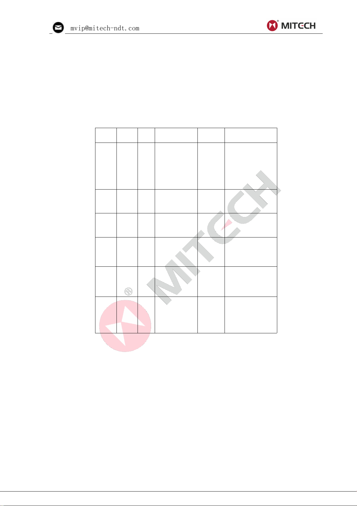
1.4 Transducer Technical Parameters
Model
Freq
MHz
ΦmmMeasuring
Range
Lower
limit
Description
N02
2.5
14
3.0mm~
300.0mm(In
Steel)
40mm (in Gray
Cast Iron
HT200)
20mm
for thick, highly
attenuating, or
highly scattering
materials
N05510
1mm~
600.0mm
(In Steel)
Φ20mm×
3.0mm
Normal
Measurement
N05
/90°
5
10
1mm~
600.0mm
(In Steel)
Φ20mm×
3.0mm
Normal
Measurement
N0776
0.65mm~
200.0mm
(In Steel)
Φ15mm×
2.0mm
For thin pipe wall
or small curvature
pipe wall
measurement
HT5512
1~600mm
(In Steel)
30mm
For high
temperature
(lower than 300℃)
measurement.
P5EE
5
10
P-E: 2~600mm
E-E: 3~100mm
Φ20mm×
3.0mm
Normal
Measurement
and
trough-coating
thickness testing
sale@ponpe.com
ponpe.com
Table 1.1 Transducer Technical Parameters
Page 6

mvip@mitech-ndt.com
1.5 Configuration
No
Item
Qty.
Note
Standar
d Config.
1
Main body
1
2
Probe P5EE(5MHz)
1
3
Couplant
1
4
Instrument Case
1
5
Operating manual
1
6
Alkaline battery
2
AA size
Optional
Config.
7
Probe N02 (2.5MHz)
8
Probe N05/90°(5MHz)
See Table1.1
9
Probe N05 (5MHz)
10
Probe N07(7MHz)
11
Probe HT5(5MHz)
12
Data Pro Software
1
13
USB Cable
1
14
Portable Bluetooth
thermal printer
1
Including
charger,
manual and
other parts.
1. The Main Body 2. Keypad 3. TFT display
sale@ponpe.com
Table 1.2 Instrument Configurations
1.6 Operating Conditions
Operating Temperature: 0℃~+50℃;
Storage Temperature:-20℃~+70℃
Relative Humidity ≤80%;
The surrounding environment should avoid of vibration, strong magnetic field, corrosive medium
and heavy dust.
2 Structure Feature
4. Battery cover 5.P/R socket 6. Probe zero disc 7.Bluetooth status 8.USB interface 9.
Probe
10. Label
Page 7
mvip@mitech-ndt.com
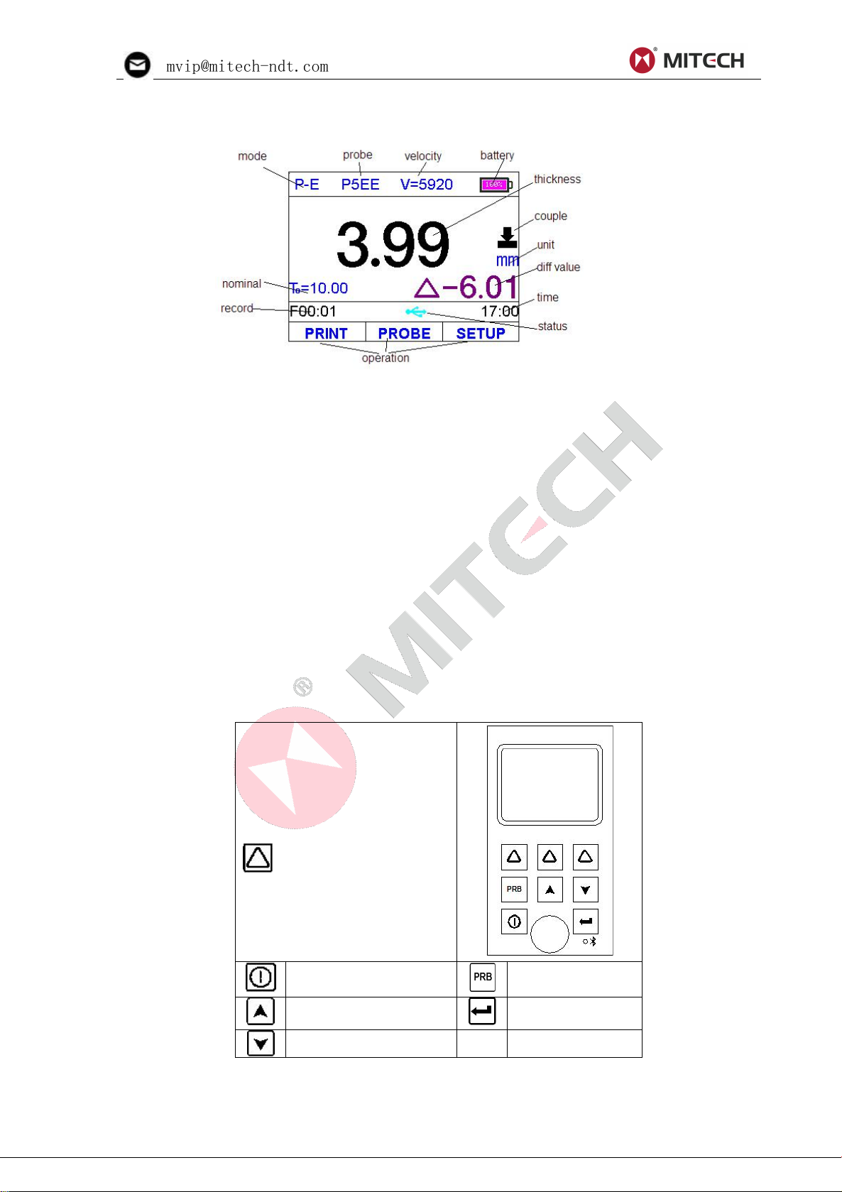
2.1 Main Screen
The instrument is designed to
give the user quick access to
all of the instrument’s
functions. Its easy-to-use menu
system allows any function to
be accessed with several key
presses.
Function keys to select
accordingly the function on the
screen. In the following
sections of this manual, they
are referred to as F1, F2 and
F3 from left to right.
Turn the instrument
on/off , or Cancel
Probe-Zero
operation
Plus or scroll up
Confirm/Enter
Minus or scroll down
sale@ponpe.com
ponpe.com
Mode: "E-E" indicating the instrument work in the Echo-Echo mode; "P–E” indicating it work in the
Pulse-Echo mode;
Probe: Probe selection
Velocity: Sound velocity
Battery: Indicating the rest capacity of the battery.
Thickness: Last test result
Unit: mm or inch
Diff value: Differential result when working in diff mode.
Time: System time
Status: USB and Bluetooth communication status
Operation: Indicate the information about the ongoing operation;
Record: Shows selected data group name and record count.
Couple: Indicate the coupling status
Nominal thickness: the nominal thickness of the test piece
2.2 Keypad Definitions
The red LED on the keyboard is used to indicate the Bluetooth communication status as described
in the following table:
Page 8

mvip@mitech-ndt.com
Bluetooth role
LED status
Bluetooth status
Host mode
Fast glittering (150 ms
on, 150 ms turn off)
Searching and
connecting
Fast glittering 5 times
and then turn off after 2
seconds
connecting
Always on
Connected
Slave mode
Slow glittering (800 ms
on, 800 ms turn off)
connecting
Always on
Connected
sale@ponpe.com
3 Test Preparation
3.1 Transducer Selection
The gauge is inherently capable of performing measurements on a wide range of materials,
from various metals to glass and plastics. Different types of material, however, will require the use
of different transducers. Choosing the correct transducer for a job is critical to being able to easily
perform accurate and reliable measurement. The following paragraphs highlight the important
properties of transducers, which should be considered when selecting a transducer for a specific
job.
Generally speaking, the best transducer for a job is one that sends sufficient ultrasonic energy
into the material being measured such that a strong, stable echo is received by the gauge. Several
factors affect the strength of ultrasound as it travels. These are outlined below:
Initial Signal Strength. The stronger a signal is to begin with, the stronger its return echo will
be. Initial signal strength is largely a factor of the size of the ultrasound emitter in the transducer. A
large emitting area will send more energy into the material being measured than a small emitting
area. Thus, a so-called “1/2 inch” transducer will emit a stronger signal than a “1/4 inch”
transducer.
Absorption and Scattering. As ultrasound travels through any material, it is partly absorbed. If
the material through which the sound travels has any grain structure, the sound waves will
experience scattering. Both of these effects reduce the strength of the waves, and thus, the
gauge’s ability to detect the returning echo. Higher frequency ultrasound is absorbed and
scattered more than ultrasound of a lower frequency. While it may seem that using a lower
frequency transducer might be better in every instance, low frequencies are less directional than
high frequencies. Thus, a higher frequency transducer would be a better choice for detecting the
exact location of small pits or flaws in the material being measured.
Geometry of the transducer. The physical constraints of the measuring environment
sometimes determine a transducer’s suitability for a given job. Some transducers may simply be
too large to be used in tightly confined areas. Also, the surface area available for contacting with
the transducer may be limited, requiring the use of a transducer with a small wearface. Measuring
on a curved surface, such as an engine cylinder wall, may require the use of a transducer with a
matching curved wearface.
Temperature of the material. When it is necessary to measure on surfaces that are
exceedingly hot, high temperature transducers must be used. These transducers are built using
special materials and techniques that allow them to withstand high temperatures without damage.
Additionally, care must be taken when performing a “Probe-Zero” or “Calibration to Known
Thickness” with a high temperature transducer.
Selection of the proper transducer is often a matter of tradeoffs between various
characteristics. It may be necessary to experiment with a variety of transducers in order to find one
that works well for a given job.
Page 9

mvip@mitech-ndt.com
The transducer is the “business end” of the instrument. It transmits and receives ultrasonic
its use.
sale@ponpe.com
ponpe.com
sound waves that the instrument uses to calculate the thickness of the material being measured.
The transducer connects to the instrument via the attached cable, and two coaxial connectors.
When using transducers, the orientation of the dual coaxial connectors is not critical: either plug
may be fitted to either socket in the instrument.
The transducer must be used correctly in order for the instrument to produce accurate,
reliable measurements. Below is a short description of the transducer, followed by instructions for
Left figure is a bottom view of a typical transducer. The two semicircles of the wearface are
visible, as is the barrier separating them. One of the semicircles is responsible for conducting
ultrasonic sound into the material being measured, and the other semicircle is responsible for
conducting the echoed sound back into the transducer. When the transducer is placed against the
material being measured, it is the area directly beneath the center of the wearface that is being
measured.
Right figure is a top view of a typical transducer. Press against the top with the thumb or index
finger to hold the transducer in place. Moderate pressure is sufficient, as it is only necessary to
keep the transducer stationary, and the wearface seated flat against the surface of the material
being measured.
3.2 Condition and Preparation of Surfaces
In any ultrasonic measurement scenario, the shape and roughness of the test surface are of
paramount importance. Rough, uneven surfaces may limit the penetration of ultrasound through
the material, and result in unstable, and therefore unreliable, measurements. The surface being
measured should be clean, and free of any small particulate matter, rust, or scale. The presence of
such obstructions will prevent the transducer from seating properly against the surface. Often, a
wire brush or scraper will be helpful in cleaning surfaces. In more extreme cases, rotary sanders or
grinding wheels may be used, though care must be taken to prevent surface gouging, which will
inhibit proper transducer coupling.
Extremely rough surfaces, such as the pebble-like finish of some cast iron, will prove
most difficult to measure. These kinds of surfaces act on the sound beam like frosted
glass on light, the beam becomes diffused and scattered in all directions.
In addition to posing obstacles to measurement, rough surfaces contribute to excessive wear
of the transducer, particularly in situations where the transducer is “scrubbed” along the surface.
Transducers should be inspected on a regular basis, for signs of uneven wear of the wearface. If
the wearface is worn on one side more than another, the sound beam penetrating the test material
may no longer be perpendicular to the material surface. In this case, it will be difficult to exactly
locate tiny irregularities in the material being measured, as the focus of the sound beam no longer
lies directly beneath the transducer.
4 Startup
4.1 Power Supply
Two AA size alkaline batteries are needed as the power supply.
The battery compartment is situated at the instrument back. The cover is fastened with two
Page 10

mvip@mitech-ndt.com
screws. To insert the batteries:
1. Loosen the two screws of the battery cover.
2. Lift the cover off upward.
3. Insert the batteries into the battery compartment.
4. Close the battery compartment and fasten the screws.
5. Turn on the instrument to make sure the battery is installed correctly and firmly.
The start display of the
instrument appears as right
figure.
Press F1 key to change to
a different language.
Press F3 key to skip the
booting check process and
enter the measure mode
immediately.
The instrument carries out
a self-check and then
switches over to the measure
mode automatically if there is
no key operation.
The instrument is now
ready for the first
measurement.
sale@ponpe.com
4.2 Connecting the Probe
To prepare the instrument for operation, you have to connect a probe to it. The instrument is
available with the Lemo socket connectors.
When connecting a probe to the instrument, it’s not only important that the physical connection
be properly made. It’s also important that the instrument is properly configured to work with the
installed probe.
4.3 Starting the Instrument
To start the instrument, press down until display activates. While the device is booting a
splash screen, the serial number of the unit, the installed software version, the date and time of the
system appear on the display.
The instrument will automatically reload last settings. It has a special memory that retains all of
its settings even when the power is off.
To shut off the instrument, keep pressing down key until shutting down message appears.
The gauge also has auto power off function to save battery capacity. If there is no operation
during a specified period of time (setting as the Auto Poweroff delay), the gauge will be powered
off automatically.
Note: The instrument will shut off automatically if the battery capacity level is too low.
4.4 Configuration of the Standby Settings
To save battery power, the device supports the following power states:
Run state – The main unit is running at full frequency
Standby state – After 5 seconds (default setting) the brightness of the LCD display is tuned to a
low level and the CPU is running at reduced frequency. This has no effects on the data or the
memories. Pressing any key or performing a measurement sets the unit back to run state and the
brightness is tuned back.
Power off state – After 2 minutes (default setting) the instrument changes from standby state to
Page 11

mvip@mitech-ndt.com
power off state. The main unit and the display is switched off and consumes almost no energy.
To switch between P-E mode
and E-E mode, press in
the Test Settings dialog.
In the Probe Model dialog,
Use the key and the
key to scroll to the probe
model currently being used.
Finally press or F3 to
confirm the selection. Or press
to cancel and exit.
2 Press the key to
activate the probe zero
mode, as right figure.
3 Apply a single droplet of
ultrasonic couplant to the
face of the metal
probe-disc.
6.
sale@ponpe.com
ponpe.com
Pressing any key will stop the unit entering power off state while it prompts out “Idle Timeout!” and
return back to run state.
The change from run state to standby state is controlled by Display standby delay setting. The
time delay can be configured by the user in the Display Standby Delay dialog box. The main unit
can be reset to run state by any user activity while in standby state.
5 Operations
5.1 Setting the Work Mode
Often times users and inspectors in the field are faced with coated materials such as pipes and
tanks. Typically inspectors will need to remove the paint or coating prior to measuring, or allow for
some fixed amount of error introduced by the paint or coating thickness and velocity.
The error can be eliminated with this gauge by using a special Echo-Echo mode to perform
measurements for applications such as this. The gauge gives you this feature in a simple way
eliminating the need to remove the paint or coating.
5.2 Probe Selection
Be sure to set the right probe model to the instrument. Otherwise, there will be erroneous.
5.3 Perform Probe Zero
Note: Probe Zero operation applies only to Pulse-Echo mode. Do not perform Probe Zero in
Echo-Echo mode.
The key is used to “zero” the instrument in much the same way that a mechanical
micrometer is zeroed. If the gauge is not zeroed correctly, all the measurements that the gauge
makes may be in error by some fixed value. When the instrument is “zeroed”, this fixed error value
is measured and automatically corrected for all subsequent measurements. The instrument may
be “zeroed” by performing the following procedure.:
1 Plug the transducer into the instrument. Make sure that the connectors are fully engaged.
Check that the wearface of the transducer is clean and free of any debris.
4 Press the transducer against the probe disc, making sure that the transducer sits flat against
the surface.
Page 12

mvip@mitech-ndt.com
5 When the progress bar shows complete, remove the transducer from the probe disc. If
7. Press while in probe zero mode will stop the probe zero operation and return to the
In the Set Velocity dialog,
press F1/F2 and / keys
to adjust the velocity value
up or down, until it matches
the sound velocity of the
material to be measured.
You can also press the
key to select among the
preset commonly using
velocities.
1 Perform a Probe-Zero on the standard 4.00 mm disc.
2 Apply couplant to the sample piece.
3 Press the transducer against the sample piece, making sure that the transducer sits flat
4 Having achieved a stable reading, remove the transducer. If the displayed thickness
sale@ponpe.com
necessary, repeat this procedure for times.
6 At this point, the instrument has successfully calculated its internal error factor, and will
compensate for this value in any subsequent measurements. When performing a “probe zero”, the
instrument will always use the sound velocity value of the built-in probe-disc, even if some other
velocity value has been entered for making actual measurements. Though the instrument will
remember the last “probe zero” performed, it is generally a good idea to perform a “probe zero”
whenever the gauge is turned on, as well as any time a different transducer is used. This will
ensure that the instrument is always correctly zeroed.
measurement mode.
5.4 Sound Velocity Calibration
In order for the gauge to make accurate measurements, it must be set to the correct sound
velocity for the material being measured. Different types of material have different inherent sound
velocities. If the gauge is not set to the correct sound velocity, all of the measurements the gauge
makes will be erroneous by some fixed percentage.
The One-Point calibration is the simplest and most commonly used calibration procedure
optimizing linearity over large ranges. The Two-point calibration allows for greater accuracy over
small ranges by calculating the probe zero and velocity.
Note: One and Two point calibrations must be performed on material with the paint or coating
removed. Failure to remove the paint or coating prior to calibration will result in a multi material
velocity calculation that may be different from the actual material velocity intended to be
measured.
5.4.1 Calibration to a known velocity
Note: This procedure requires that the operator knows the sound velocity of the material to be
measured. A table of common materials and their sound velocities can be found in Appendix A of
this manual.
5.4.2 Calibration to a known thickness
Note: This procedure requires a sample piece of the specific material to be measured, the
exact thickness of which is known, e.g. from having been measured by some other means.
against the surface of the sample. The display should show some thickness value, and the
coupling status indicator should appear steadily.
Page 13

mvip@mitech-ndt.com
changes from the value shown while the transducer was coupled, repeat step 3.
5 Press the / key
to enter the “Input Nominal
Thickness” dialog. See right
figure.
6 Press F1/F2 and
/ to input the thickness
value, until it matches the
thickness of the sample
piece.
7
8 Press /F3 to confirm the input. The gauge exits from the input dialog and return to the
9 The gauge is now ready to perform measurements.
1 Perform a Probe-Zero on the standard disc.
2 Apply couplant to the sample piece.
3 Press the transducer against the sample piece, at the first/second calibration point,
4 Having achieved a stable reading, remove the transducer. If the displayed thickness
5 Press the / key to enter the “Input Nominal Thickness” dialog. See right figure.
6 Press F1/F2 and
/ to input the thickness
value, until it matches the
thickness of the sample
piece. Then press to
calibrate the second point,
see the following figure.
7
8
9
10 Figure: Testing the
second point during Two
Point Calibration.
11
12
13 Repeat Step 2 to Step 6 on the second calibration point.
14 Finally press the /F3 to complete Two Point Calibration procedure. The gauge is now
sale@ponpe.com
ponpe.com
measurement mode. It is now displaying the sound velocity value it has calculated based on the
thickness value that was input.
5.4.3 Two Point Calibration
Note: This procedure requires that the operator has two known thickness points on the test
piece that are representative of the range to be measured.
making sure that the transducer sits flat against the surface of the sample. The display should
show some (probably incorrect) thickness value, and the coupling status indicator should appear
steadily.
changes from the value shown while the transducer was coupled, repeat step 3.
ready to perform measurements within this range.
5.5 Making Measurements
When the tool is displaying thickness measurements, the display will hold the last value
measured, until a new measurement is made.
Page 14

mvip@mitech-ndt.com
In order for the transducer to do its job, there must be no air gaps between the wear-face and
Three view modes can be
selected to show the
measured value: Normal
Mode, Scan Mode and Diff
Mode.
Normal Mode. As shown in
right figure, it shows the last
test thickness value.
sale@ponpe.com
the surface of the material being measured. This is accomplished with the use of a “coupling” fluid,
commonly called “couplant”. This fluid serves to “couple”, or transfer, the ultrasonic sound waves
from the transducer, into the material, and back again. Before attempting to make a measurement,
a small amount of couplant should be applied to the surface of the material being measured.
Typically, a single droplet of couplant is sufficient.
After applying couplant, press the transducer (wearface down) firmly against the area to be
measured. The coupling status indicator should appear, and a digit number should appear in the
display. If the instrument has been properly “zeroed” and set to the correct sound velocity, the
number in the display will indicate the actual thickness of the material directly beneath the
transducer.
If the coupling status indicator does not appear, not stable, or the numbers on the display seem
erratic, firstly check to make sure that there is an adequate film of couplant beneath the transducer,
and that the transducer is seated flat against the material. If the condition persists, it may be
necessary to select a different transducer (size or frequency) for the material being measured.
While the transducer is in contact with the material that is being measured, the instrument will
perform four measurements every second, updating its display as it does so. When the transducer
is removed from the surface, the display will hold the last measurement made.
Note:Occasionally, a small film of couplant will be drawn out between the transducer and the
surface as the transducer is removed. When this happens, the gauge may perform a
measurement through this couplant film, resulting in a measurement that is larger or smaller than it
should be. This phenomenon is obvious when one thickness value is observed while the
transducer is in place, and another value is observed after the transducer is removed. In addition,
measurements through very thick paint or coatings may result in the paint or coating being
measured rather than the actual material intended. The responsibility for proper use of the
instrument, and recognition of these types of phenomenon, rests solely with the user of the
instrument.
5.6 View Mode Setting
Page 15

mvip@mitech-ndt.com
Scan Mode. Besides the
last test thickness value, it
also shows the minimum
thickness value and the
maximum thickness during
the test.
Press will reset the
minimum and maximum
value.
Diff Mode. Shows both the
last test thickness value
and the differential
thickness value (between
the absolute thickness
value and the nominal
thickness value)
While the gauge excels at making single point measurements, it is sometimes desirable to
Press F1/F2 key to
move the highlight cursor;
Press arrow keys to
increase/decrease the
values.
Press or F3 key to
confirm the setting.
Press key to cancel the
change and exit.
For the gauge, test
results beyond the limits will
be displayed with red color
to alarm the user. To
change the limit setting,
Press F1/F2 key to
move the highlight cursor;
Press arrow keys to
increase/decrease the
values.
Press or F3 key to
confirm the setting.
Press key to cancel the
sale@ponpe.com
ponpe.com
ponpe.com
examine a larger region, searching for the thinnest point. The gauge includes a feature, called
Scan Mode, which allows it to do just that.
In normal mode, the gauge performs and displays ten measurements every second, which is
quite adequate for single measurements. In Scan Mode, however, the gauge performs over ten
measurements every second, and displays the readings while scanning. While the transducer is in
contact with the material being measured, the gauge is keeping track of the minimum and
maximum measurement it finds. The transducer may be “scrubbed” across a surface, and any
brief interruptions in the signal will be ignored.
5.7 Nominal Thickness Setting
In Differential measurement mode, it needs to set the nominal thickness value of the test
piece. The setting method is as below:
5.8 Limit Setting
Page 16

mvip@mitech-ndt.com
change and exit
5.9 Changing Resolution
The gauge has
selectable display
resolution, which is 0.1mm
and 0.01mm.
Activate the Memory
Manager dialog as right
figure.
Press to move the
cursor; Press or F3 key
to open the View Record
Data dialog, see next
figure.
Press to move the
cursor to the desired
record.
Press F3 to delete the
focused record.
Press F2 to clear all the
records of this group.
Press /F1 to exit.
sale@ponpe.com
When the resolution is set to 0.01mm, the tested piece surface should be smooth to get
accurate test result. When measuring rough surface or coarse grained materials, it is suggested to
use low resolution.
5.10 Memory Management
5.10.1 Store a Record
By simply pressing the key after a new measurement reading appears, the measured
thickness value will be saved to current selected data group. It is added as the last record of the
group.
5.10.2 View the Saved Record
This function provides the user with the ability to view the records in a desired data group
previously saved in memory. Following is the steps:
5.10.3 Select As Current Data Group
There are 100 data groups (F00 ~ F99) inside the gauge that can be used to store the
measurement values. At most 100 records (thickness values) can be stored to each group. You
can change the destination data group to store the measured values as following.
Page 17

mvip@mitech-ndt.com
Activate the Memory
Manager dialog. Press
to focus on the desired data
group. Press F2 to prompt
out the commands list.
Then select the command
“Set” and press to
confirm.
After finished the above steps, the new selected data group will be set as current data group to
Activate the Memory
Manager dialog.
Press to focus on
the desired data group.
Press F2 to prompt out
the commands list. Then
select the command
“Clear” and press to
confirm.
The setting can be
changed by scrolling with
F1 (increase) and F2
(decrease) keys, or by
pressing arrow keys.
Press or F3 key to
confirm the setting.
Press key to cancel
the change and close the
dialog box.
sale@ponpe.com
ponpe.com
store the new coming testing results.
5.10.4 Clear Selected Group
The user may require the contents of an entire data group be completely cleared of all
measurements. This would allow the user to start a new list of measurements starting at storage
location No.00. The procedure is outlined in the following steps.
If the “Clear All” command is selected and confirmed, all the data groups of the gauge will be
cleared.
Note: Once cleared, the data is not able to be recovered!
5.11 Key Sound Setting
Key sound can be configured to on or off. When the key sound is set to on, the buzzer inside
the main unit would make a short audible alarm while press the key each time.
5.12 Warn Sound Setting
Warning sound can be configured to on or off. If the warning sound is set to on, the buzzer
inside the main unit would make a long audible alarm when a new measured value appears. When
the main unit gives out some operation warnings it will also give a alarm sound if the setting is on.
5.13 LCD Brightness Setting
The different brightness of the LCD will affect battery standby time and continuously working
time. .
The instrument consumes less current in lower brightness and consequently increases the
operating time.
Page 18

mvip@mitech-ndt.com
Note: For saving power, lower down the LCD brightness in good light environment.
See right figure of Display
Standby Delay dialog box
for the items of the settings.
Press arrow keys or F2 key
to select the desired item.
Selecting “Disable” item will
forbid the main unit
switching into standby state.
The time delay can be
configured by the user in the
auto shutdown delay dialog
box.
Press arrow keys or F2
key to select the desired item.
Selecting “Disable” item
will forbid the main unit
switching automatically into
power off state.
The instrument supports
both metric and imperial unit
systems.
In the System
Configuration dialog, press
on the Unit System item
to switch back and forth
between imperial and metric
unit system.
sale@ponpe.com
5.14 Display Standby Setting
Standby state lower down the LCD brightness and puts the CPU in a power conserving mode.
The change from run state to standby state is controlled by the setting of the Display standby
delay.
The main unit goes into standby state after a period of time as selected. Carry out a test or
press any key to reactivate the main unit from standby state.
5.15 Auto Poweroff Setting
The change from standby state to power off state is controlled by the setting of automatic
shutdown delay.
Note: If the voltage of the battery is too low, the LCD screen will show “Battery Exhausted!”,
then power off automatically.
5.16 Changing Unit System
5.17 Date and Time setting
For a correct documentation you should always make sure that you are using the correct date
and time setting. Open the system time dialog to set date and time of the instrument system.
The format for date: Year-Month-Date
The format for time: Hour–Minute- Second
Page 19

mvip@mitech-ndt.com
Use F1 and F2 keys to
move the cursor. Use arrow
keys to increase/decrease the
values;
Press /F3 key to confirm
the setting. Press key to
cancel the setting change and
close the dialog box.
Once set, the internal clock of the instrument will maintain the current date and time.
Use the arrow keys and
F2 key to select the operating
language.
Press or F3 key to
confirm the selection.
Press key to cancel
the language change and
close the dialog box.
Information concerning the
instrument model, the
software version and the
serial number of the main unit
is displayed.
Press , , F1 or F3
key to close the dialog box.
Activate the System
Reset function. Then
you will see right dialog.
Press or F3 key to
confirm the reset
operation. Or press F1
key to cancel the reset
operation.
sale@ponpe.com
ponpe.com
5.18 Language Setting
Language of the application software can be selected.
Note: User can also change the operating language on the booting screen during startup.
5.19 Product Information
5.20 Reset System
In case the instrument can no longer be operated, or you need to make a basic initialization
(factory setting), you can reset the instrument to original.
The instrument can be reset by the System Reset function. All the stored data inside the main
unit and user calibration will be cleared during system reset. And the instrument settings will be
reset to default.
To reset the instrument:
NOTE: The effects of resetting the instrument may not be reversed.No key action should be
performed during resetting process.
5.21 Print via Bluetooth
The instrument has Bluetooth function module. It can be connected to a portable Bluetooth
thermal mini-printer for wireless printing. Operating steps to set up the bluetooth connection are as
follows:
1 Start up the Bluetooth mini-printer.
Page 20

mvip@mitech-ndt.com
2 Set the Bluetooth role of
the instrument to Master
mode.
3 The instrument will ask the
operator if need to re-search
nearby Bluetooth printer
shown as right figure.
Select “YES” for the first
time to print. Otherwise,
select “NO”.
The gauge then try to set up a connection with the mini-printer via Bluetooth. Wait for several
Print stored data group
via Bluetooth.
In the memory
manager dialog box, select
“print” will print the
selected data group.
Select “Print All” will print
all data groups stored
inside the instrument.
You can also print out
the test result directly after
each test.
On the main screen,
after each test, simple
press F1 to print out that
test result.
Lift the rubber flaps to uncover the connection port.
Insert the mini-USB end of the USB cable into the USB socket on the upside of main body.
Insert the other end into the USB port of the computer.
sale@ponpe.com
seconds. When the Bluetooth status light on the front panel of the main unit is always on, the
Bluetooth connection between the instrument and the mini-printer is established successfully.
Note: When the instrument is turned off and once again turned on, the Bluetooth
function module will be automatically shut off to save power.
5.22 USB Communication
The instrument is equipped with a USB port on upper left of the instrument.
The PC can be connected with the instrument via the USB cable.
After installing the DataPro software and the USB driver, you can download the stored test data
from the tester.
The DataPro software helps manage and format stored data for high-speed transfer to the PC.
Data can be printed or easily copied and pasted into word processing files and spreadsheets for
further reporting needs. New features include live screen capture mode and database tracking.
Detailed information of the communication software and its usage refer to the software manual.
Page 21

mvip@mitech-ndt.com
6. Measuring Technologies
Keep it away from vibration, strong magnetic field, corrosive medium, dumpiness and dust.
With original packing, transport is allowed on the third grade highway.
sale@ponpe.com
ponpe.com
6.1 Measuring Method
Single point measuring method: Put the probe to any point in the workpiece, the instrument
will show the probe located place thickness.
Two point measuring method: Using the probe to measure two times in the same point of the
tested piece, in two measuring, the probe parting plane keep 90º, the smaller value should be the
thickness of this point.
Multi-point measurement method: Taking times testing in an approximately 30 mm diameter
circular around, the minimum value is the thickness value of the tested piece.
Continuous measurement method: using single point measurement to take continuous
measurement along the specified path with less 5mm interval, the minimum value is the thickness
value of the tested piece.
6.2 Wall Measurement
During measuring, the probe parting plane can be along with the tube axis or vertical tube
axis. If meeting larger tube diameter, you should measure at the vertical axis. And when the tube
diameter is smaller, you should measure in both directions and the minimum value is thickness
value.
7 Servicing
When the gauge appears some other abnormal phenomena, please do not dismantle or adjust
any fixedly assembled parts. Fill in and present the warranty card to us. The warranty service can
be carried on.
8 Transport and Storage
Storage in ordinary temperature.
Page 22

mvip@mitech-ndt.com
Appendix A Sound Velocities
Material
Sound Velocity
in/µs
m/s
Aluminum
0.250
6340-6400
Steel, common
0.233
5920
Steel, stainless
0.226
5740
Brass
0.173
4399
Copper
0.186
4720
Iron
0.233
5930
Cast Iron
0.173-0.229
4400-5820
Lead
0.094
2400
Nylon
0.105
2680
Silver
0.142
3607
Gold
0.128
3251
Zinc
0.164
4170
Titanium
0.236
5990
Tin
0.117
2960
Epoxy resin
0.100
2540
Ice
0.157
3988
Nickel
0.222
5639
Plexiglass
0.106
2692
Polystyrene
0.092
2337
Porcelain
0.230
5842
PVC
0.094
2388
Quartz glass
0.222
5639
Rubber, vulcanized
0.091
2311
Teflon
0.056
1422
Water
0.058
1473
sale@ponpe.com
Page 23

mvip@mitech-ndt.com
Appendix B Applications Notes
sale@ponpe.com
ponpe.com
Measuring pipe and tube
When measuring a piece of pipe to determine the thickness of the pipe wall, orientation of the
transducers is important. If the diameter of the pipe is larger than approximately 4 inches,
measurements should be made with the transducer oriented so that the gap in the wearface is
perpendicular (at right angle) to the long axis of the pipe. For smaller pipe diameters, two
measurements should be performed, one with the wearface gap perpendicular, another with the
gap parallel to the long axis of the pipe. The smaller of the two displayed values should then be
taken as the thickness at that point.
Measuring hot surfaces
The velocity of sound through a substance is dependant upon its temperature. As materials heat
up, the velocity of sound through them decreases. In most applications with surface temperatures
less than about 100℃, no special procedures must be observed. At temperatures above this point,
the change in sound velocity of the material being measured starts to have a noticeable effect
upon ultrasonic measurement. At such elevated temperatures, it is recommended that the user
perform a calibration procedure on a sample piece of known thickness, which is at or near the
temperature of the material to be measured. This will allow the gauge to correctly calculate the
velocity of sound through the hot material.
When performing measurements on hot surfaces, it may also be necessary to use a specially
constructed high-temperature transducer. These transducers are built using materials which can
withstand high temperatures. Even so, it is recommended that the probe be left in contact with the
surface for as short a time as needed to acquire a stable measurement. While the transducer is in
contact with a hot surface, it will begin to heat up, and through thermal expansion and other effects,
may begin to adversely affect the accuracy of measurements.
Measuring laminated materials
Laminated materials are unique in that their density (and therefore sound-velocity) may vary
considerably from one piece to another. Some laminated materials may even exhibit noticeable
changes in sound-velocity across a single surface. The only way to reliably measure such
materials is by performing a calibration procedure on a sample piece of known thickness. Ideally,
this sample material should be a part of the same piece being measured, or at least from the same
lamination batch. By calibrating to each test piece individually, the effects of variation of
sound-velocity will be minimized.
An additional important consideration when measuring laminates, is that any included air gaps or
pockets will cause an early reflection of the ultrasound beam. This effect will be noticed as a
sudden decrease in thickness in an otherwise regular surface. While this may impede accurate
measurement of total material thickness, it does provide the user with positive indication of air
gaps in the laminate.
Measuring through paint & coatings
Page 24

mvip@mitech-ndt.com
Measuring through paints and coatings are also unique, in that the velocity of the paint/ coating will
sale@ponpe.com
be significantly different form the actual material being measured. A perfect example of this would
be a mild steel pipe with approximately 0.6mm of coating on the surface. Where the velocity of the
pipe is 5920m/s, and the velocity of the paint is 2300m/s. If the user is calibrated for mild steel pipe
and measures through both materials, the actual coating thickness will appear to be 2.5 times
thicker than it actually is, as a result of the differences in velocity. This error can be eliminated by
using a special echo-echo mode to perform measurements for applications such as these. In
echo-echo mode, the paint/ coating thickness will be eliminated entirely and the steel will be the
only material measured.
Suitability of materials
Ultrasonic thickness measurements rely on passing a sound wave through the material being
measured. Not all materials are good at transmitting sound. Ultrasonic thickness measurement is
practical in a wide variety of materials including metals, plastics, and glass. Materials that are
difficult include some cast materials, concrete, wood, fiberglass, and some rubber.
Couplants
All ultrasonic applications require some medium to couple the sound from the transducer to the
test piece. Typically a high viscosity liquid is used as the medium. The sound used in ultrasonic
thickness measurement does not travel through air efficiently.
A wide variety of couplant materials may be used in ultrasonic gauging. Propylene glycol is
suitable for most applications. In difficult applications where maximum transfer of sound energy is
required, glycerin is recommended. However, on some metals glycerin can promote corrosion by
means of water absorption and thus may be undesirable. Other suitable couplants for
measurements at normal temperatures may include water, various oils and greases, gels, and
silicone fluids. Measurements at elevated temperatures will require specially formulated high
temperature couplants.
Inherent in ultrasonic thickness measurement is the possibility that the instrument will use the
second rather than the first echo from the back surface of the material being measured while in
standard pulse-echo mode. This may result in a thickness reading that is TWICE what it should be.
The Responsibility for proper use of the instrument and recognition of these types of phenomenon
rests solely with the user of the instrument.
Page 25

mvip@mitech-ndt.com
User Notes
Damage caused by man-made or improper keeping;
Self-dismantle or non-special repair shop dismantle;
Do not follow the requirement of service registration or warranty expired;
Consumable parts.
MITECH users have lifelong maintenance service
Free maintenance, inspection, software upgrade and etc.
China
Post code:100094
Website:www.mitech-ndt.com
Email:mvip@mitech-ndt.com
Tel:0086-10-58858658
sale@ponpe.com
ponpe.com
Warranty:
The product is guaranteed for one year since purchased. Log www.mitech-ndt.com or follow our
company official public platform to register for maintenance. Please fill the blanks as required, if
the product is not registered for maintenance, it will follow the date of manufacturer.
When applying for maintenance, please visit our official website, www.mitech-ndt.com or official
accounts, submit “online reporting to repair” sheet.
In accordance with the international relevant regulations, the following are not within the scope of
free warranty,
Service promise:
Add:Room E506B, YingChuangDongLi Park, 1# of ShangDi East Road, Haidian District, Beijing,
 Loading...