

Page 1

MITECH SURFACE
ROUGHNESS TESTER
MR200
User’s Manual
MITECH CO.,LTD.
www.mitech-ndt.com
Page 2

1
mvip@mitech-ndt.com
CONTENTS
1 Overview
..................................................................................................................................................................
2
1.1 Technical Parameters................................................................................................................................. 2
1.2 Functions &Features...................................................................................................................................2
1.3 Working Principle.........................................................................................................................................3
1.4 Instrument Configuration............................................................................................................................3
1.5 Working Conditions..................................................................................................................................... 4
2 Structure and Outline
..........................................................................................................................................
4
2.1 Main Body Structure................................................................................................................................... 4
2.2 Probe Structure............................................................................................................................................4
2.3 Display...........................................................................................................................................................5
2.4 Keypad Definitions...................................................................................................................................... 5
3. Operation
...............................................................................................................................................................
5
3.1 Connecting Probe........................................................................................................................................5
3.2 Power On/Off................................................................................................................................................5
3.3 Battery Charging..........................................................................................................................................6
3.4 Parameter Setting........................................................................................................................................6
3.5 Preparation Before Measurement............................................................................................................ 7
3.6 Start Measurement......................................................................................................................................8
3.7 Display Readings.........................................................................................................................................9
3.8 Save/Read Measurement Results..........................................................................................................10
3.9 Print Measurement Results..................................................................................................................... 10
3.10 Communication With PC........................................................................................................................ 11
3.11 Remote Control and Measurement......................................................................................................12
3.12 SD Card Instructions...............................................................................................................................12
4 Software Information
.........................................................................................................................................
12
5 Maintenance
.........................................................................................................................................................
12
5.1 Probe........................................................................................................................................................... 12
5.2 Main Unit.....................................................................................................................................................12
5.3 Battery......................................................................................................................................................... 12
5.4 Calibration Specimen................................................................................................................................12
5.5 Maintenance Notice.................................................................................................................................. 12
6 Troubleshooting
..................................................................................................................................................
13
7 Optional Accessories
........................................................................................................................................
13
7.1 Height Support & Probe Sheath............................................................................................................. 13
Height Support and Probe Sheath................................................................................................................ 13
7.2 Height Lifting Pillar.................................................................................................................................... 13
7.3 Standard Probe..........................................................................................................................................14
7.4 Curved Surface Probe.............................................................................................................................. 14
7.5 Deep Groove Probe.................................................................................................................................. 15
7.6 Small Hole Probe.......................................................................................................................................16
7.7 Extension Bar.............................................................................................................................................17
8 References
............................................................................................................................................................
17
8.1Terms............................................................................................................................................................ 17
8.2 Traversing Length of Filters..................................................................................................................... 17
8.3 Parameters Definitions............................................................................................................................. 18
8.4 Recommended Table of Sampling Length............................................................................................20
Appendix
..................................................................................................................................................................
21
Appendix I: Standard Code and Name Table..............................................................................................21
Appendix II: Roughness Parameters Display Range.................................................................................21
User Notes
................................................................................................................................................................
22
Page 3
2
mvip@mitech-ndt.com
1 Overview
The Portable surface roughness tester MR200 could give a fast, accurate test of the roughness, applied
on work site and mobile measurement. It is portable to carry, easy to operate, reliable to test and full
functional advantages. Adopted 2.7 inch OLED Screen, equipped with wireless communication module,
Micro-USB port, standard Bluetooth module and SD card, it can not only achieve wireless remote control
and measure but also can connect with PC, wireless Bluetooth printer and memorize more data.
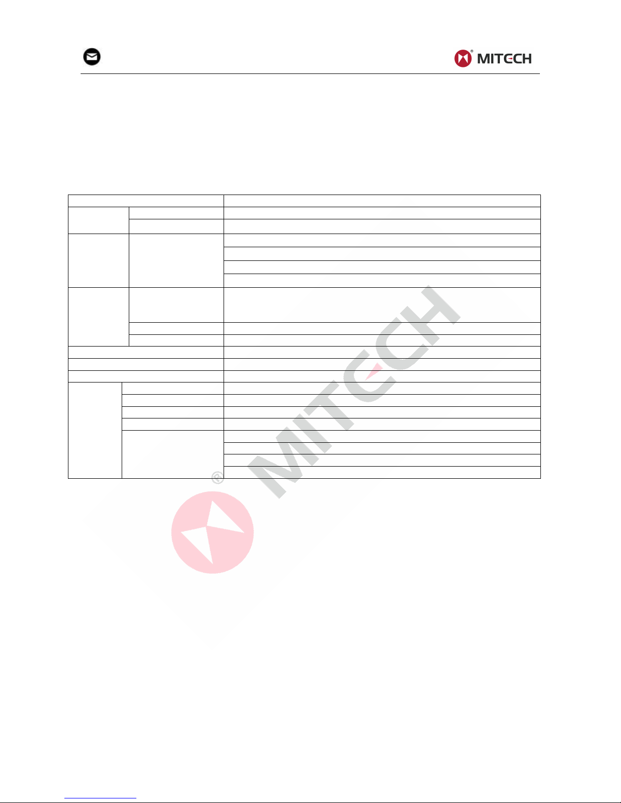
1.1 Technical Parameters
Sheet1-1
Name
Content
Measurem
ent Range
Z axis(Vertical)
320μm(Ra=80μm)
X axis(Horizontal)
17.5mm
Resolution
Z axis(Vertical)
0.01μm/±20μm
0.02μm/±40μm
0.04μm/±80μm
0.08μm/±160μm
Measurem
ent Item
Parameter
Ra, Rq, Rz, Rt, Rp, Rv, RS, RSm, Rz(JIS), Ry(JIS), RSk, R3z, Rmax,
Rpc, Rmr, Rku, RΔa, RΔq, Rδc, Ry
Rk, Rpk, Rvk, Mr1, Mr2, A1, A2, V0
Standard
ISO, ANSI, DIN, JIS
Graph
Roughness profile, Bearing ratio curve, Direct profile
Filter
RC, PC-RC, Gauss, D-P
Sample Length(Lr)
0.25,0.8,2.5mm
Assessment Length(Ln)
Ln= Lr×n, n=1~5
Probe
Measure principle
Displacement Differential Inductance
Stylus
Natural diamond, 90 cone angle, 5μmTip Radius
Measured force
<4mN
Guide head
Ruby, Longitudinal radius 40mm
Traversing speed
Lr=0.25,Vt=0.15mm/s
Lr=0.8, Vt=0. 5mm/s
Lr=2.5, Vt=1mm/s
Return, Vt=1mm/s
1.2 Functions &Features
28 Measuring parameters: Ra, Rq, Rz, Rt, Rp, Rv, RS, RSm, Rz(JIS), Ry(JIS), RSk, R3z, Rmax,
RPc, Rmr, Rku, RΔa, RΔq, Rδc, Ry; Rk, Rpk, Rvk, Mr1, Mr2, A1, A2, V0;
Adopt 320μm high accuracy inductance probe;
Four filter methods of RC, PC-RC, GAUSS, D-P ;
Compatible with four standards ISO, DIN, ANSI, JIS;
Adopt 2.7 inch 128×64 dot OLED display,without back-light and dead spot. Capable of showing
all parameters, profile graph and Chinese/English menu;
Adopt the most popular DSP chip to control and process data;
Build-in storage can memorize 20 sets of complete measurement data;
External SD Card can expand mass data storage;
Build-in wireless remote control module to remote control measurement;
Build-in Bluetooth module can be connected with the Bluetooth printer to print all the
parameters and profiles;
Build-in Micro-USB port, can communicate with PC make measurement results analysis by
data processing software;
Build-in lithium-polymer rechargeable battery and charging protection circuit;
Mechatronics design, smaller and portable to carry;
Automatic shut down for power saving, each operation step has a hit message;
Full accessories, options for curve surface probe, deep groove probe, small hole probe, tiny
hole probe, tooth surface probe, small pillar, height adjust platform, extension bar, lateral transfer
rod etc.
Page 4
3
mvip@mitech-ndt.com
1.3 Working Principle
This instrument adopts needle scanning method to test the surface roughness of the work piece.
When measuring roughness of part surface, the probe is placed on the surface of the part and then
tracing the surface at constant rate. The probe acquires the surface roughness by the sharp stylus in
probe. The roughness causes displacement of probe which results in change of inductive value of
induction coils thus generate analogue signal which is in proportion to surface roughness at output end
of phase-sensitive rectifier. This signal enters data collection system after amplification and level
conversion. After that, those collected data are processed with digital filtering and parameter calculation
by ARM chip and the measuring result can be read on OLED display. The results can be printed by
Bluetooth printer.
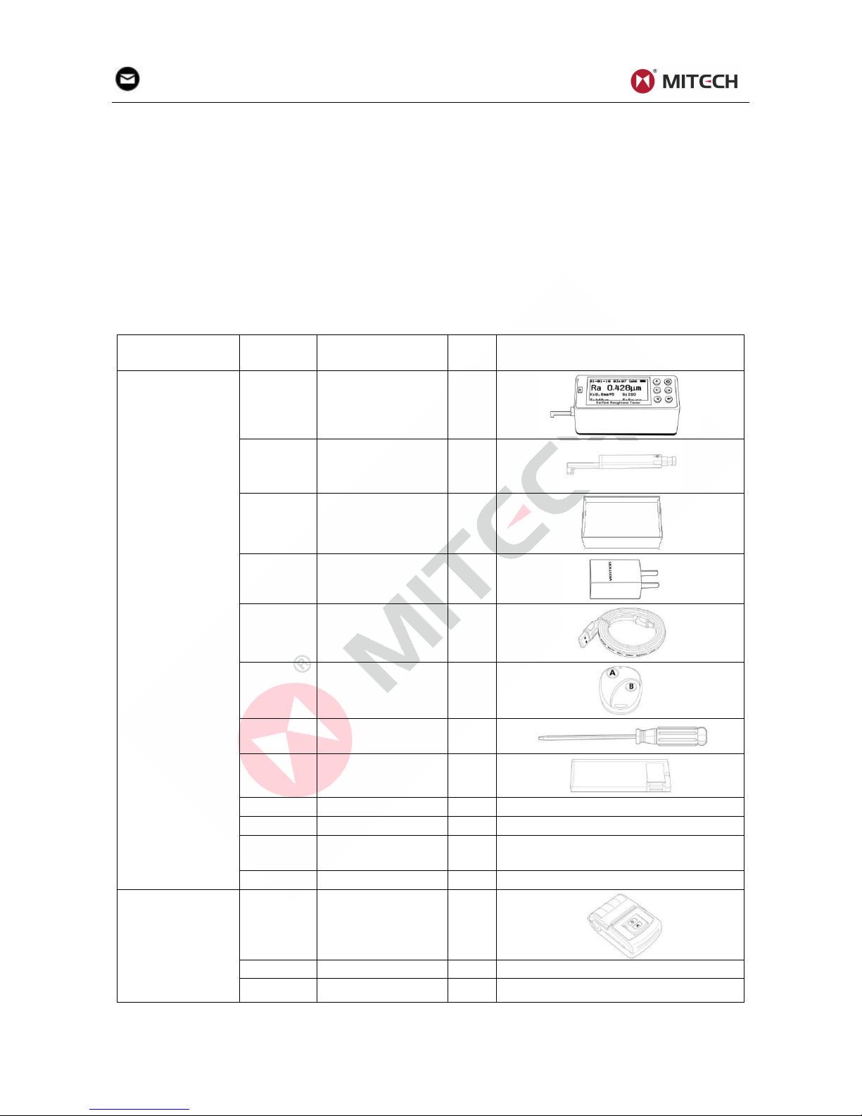
1.4 Instrument Configuration
Sheet1-2
No.
Item
QTY
Remarks
Standard
Configuration
1
M200 Main Unit
1
2
Standard Probe
1
3
Roughness
Specimen
1
4
Charger
1
5
USB Cable
1
6
Remote Control
1
7
Straight
Screwdriver
1
8
Specimen Plate
1
9
User’s Manual
1
10
Packing List
1
11
Product Certificate
1
12
Warranty Card
1
Optional
Configuration
1
Bluetooth Printer
1
2
AC Adapter
1
3
Printer Paper
1
Notes:
Please check the instrument and spare parts when getting the instrument. If anything missing
please contact the manufacturer.
Page 5
4
mvip@mitech-ndt.com
1.5 Working Conditions
Ambient temperature: -20℃~+50℃;
Storage temperature: -30℃~+70℃;
Relative humidity: ≤90%;
The surrounding environment should avoid of vibration, strong magnetic field, corrosive
medium and heavy dust.
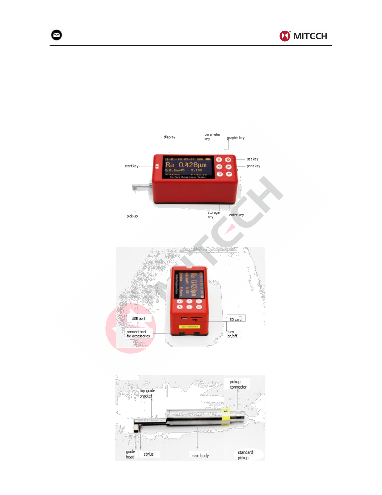
2 Structure and Outline
2.1 Main Body Structure
2.2 Probe Structure
Page 6
5
mvip@mitech-ndt.com
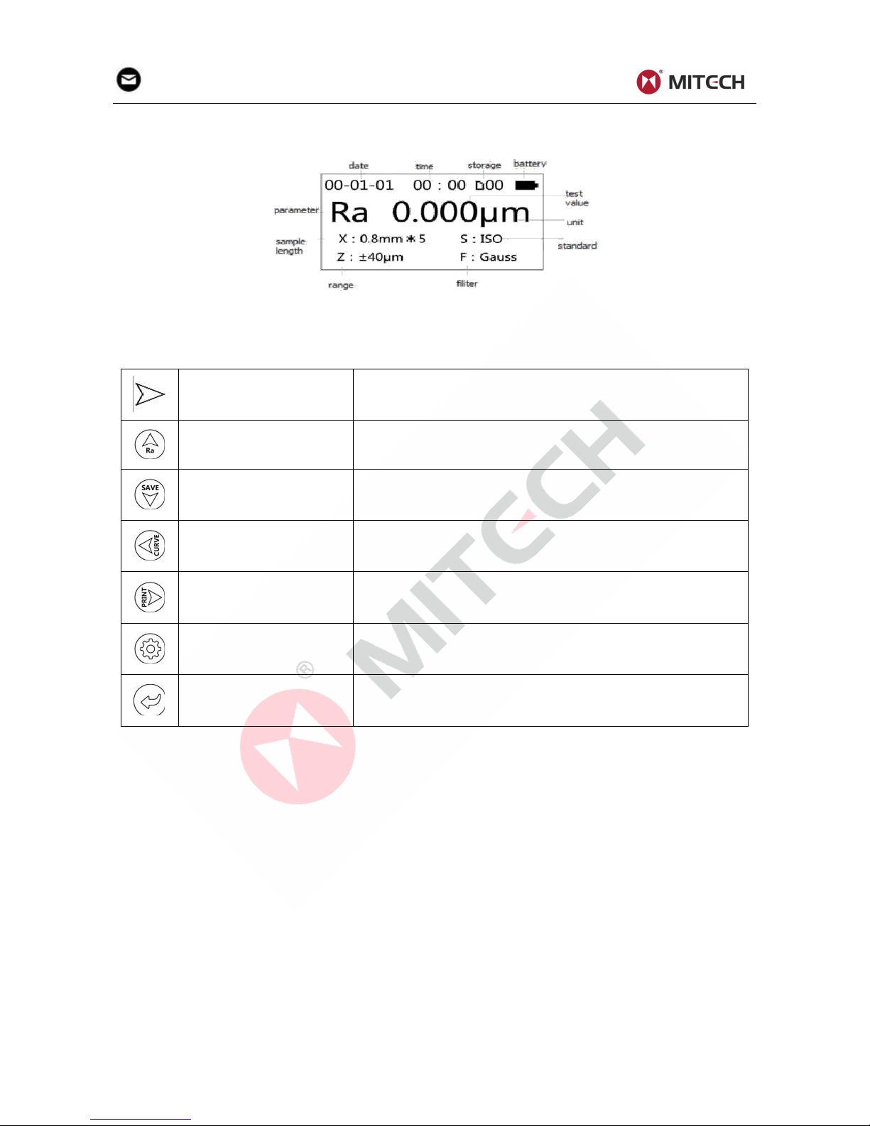
2.3 Display
2.4 Keypad Definitions
Sheet2-1
Start key
Used to start measuring.
Up arrow/Parameter key
Press this key to enter the parameter item, press the set key
to exit.
Down arrow/Storage key
Press this key to enter saving record interface.
Left arrow/Graphic key
Press this key to enter graphic item, showing curved, graphic,
bearing ratio curve and others.
Right arrow/Print key
Press this key to start Bluetooth printer for printing.
Set/Menu key
Press this key to enter setting, long press to enter main
menu.
Enter key
Press this key to show the location of the stylus, press again
to exit. In other interface, this key is used to confirm the
modify result or exit the present interface.
Notes:
In other interface, the unified regulation for up, down, left, right four arrows function keys is as
follows: up and down arrows to switch for selecting item; left and right arrows to adjust and
setting specific figures and values.
3. Operation
3.1 Connecting Probe
To ensure the stylus down, the probe is plugged into the host connection socket and pushed lightly to the
end. When pulling out, first pull out the probe from the connection socket, then take it out slowly from the
driver. The entire operation should avoid damage to the probe.
Notes:
The probe stylus is a key part of the instrument. In the plugging in and pulling out process, we
should be careful not to touch the stylus to avoid damage.
3.2 Power On/Off
The instrument switch located in the lower-left corner in panel showed as 2.1 instrument side back
figure.
Page 7
6
mvip@mitech-ndt.com
3.3 Battery Charging
When MR200 appears the low voltage tips or could not boot, it should be charging to the promptly. When
charging, put the charger into the micro-USB port, then put the charger into the socket. This instrument
adopts Li-poly battery, without memory effect, could be charged at any time. Red light indicates charging,
the green light indicates charging finished. The complete charging time is approximate 3-4 hours. It may
damage the battery for charging long time. When the instrument leaves the factory, the battery switch is
off.
3.4 Parameter Setting
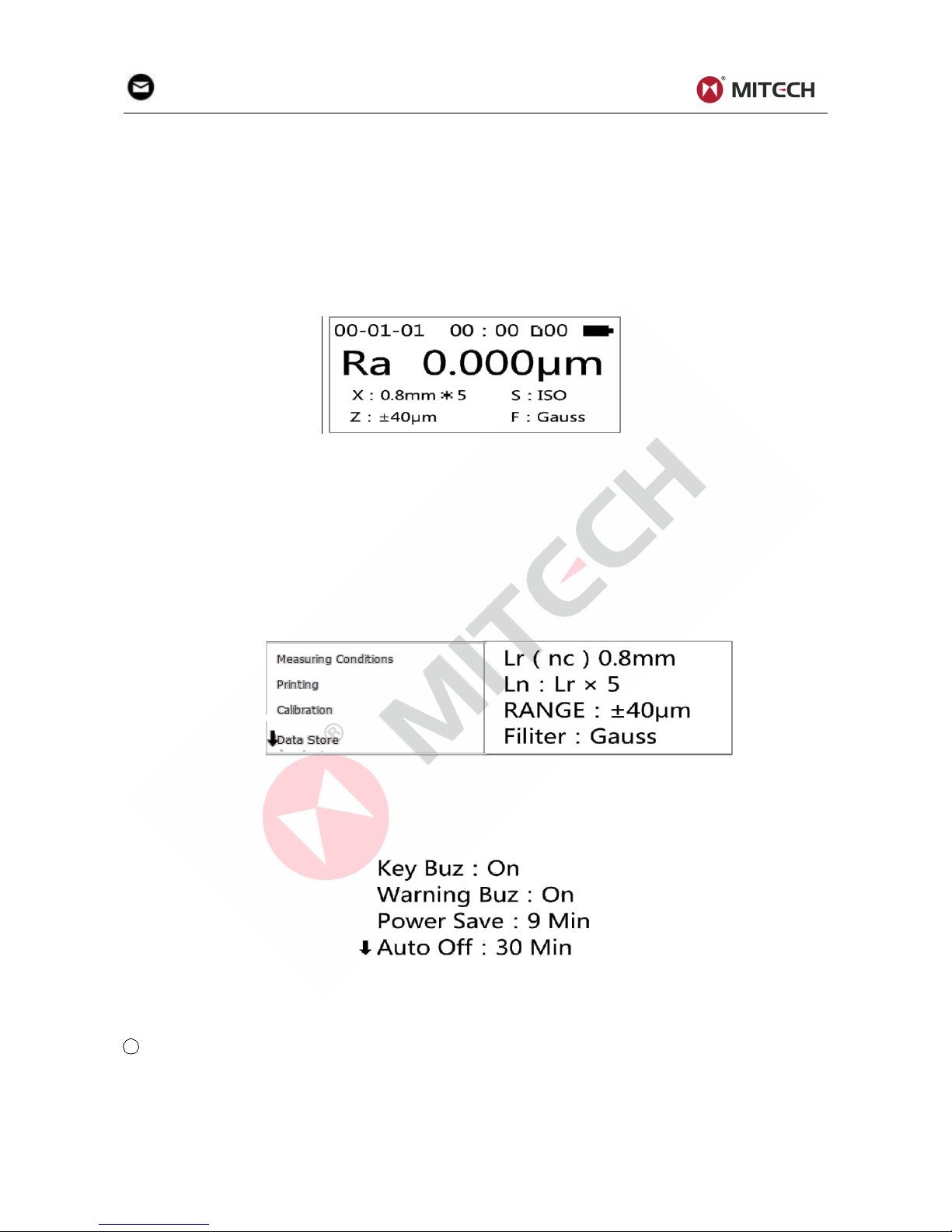
In the main interface, press "Settings button" enter the main menu
Main Interface
3.4.1Measuring Conditions Setting
Measurement conditions setting by two ways: Quick settings and Menu settings.
Quick Setting: In the main menu, press "Settings button" enter quick setup mode, follow the cursor,
modify the measurement conditions through the up, down, right and left arrows, press the "Enter button"
to confirm exit.
Menu Setting: In the main menu mode, press "Settings button" enter the menu setting mode, select
"Measurement condition setting", you can modify the "Sample length", "Evaluation length", "Range",
"Filter", "Standard", " Parameters "," C (rmr) "," C (rpc) "," Rmr (rδc) "," Unit of measurement ".
Main Menu Conditions Setting
3.4.2 System Setting
In main interface, long press setting to enter menu setting, choose system setting, enter the sub-menu.
In this menu, you can set: “Key Buz”, “Warning Buz”, “Power Save”, “Auto Off”, “Time Calibration”, “Low
Noise Test”, “Display Test”, “Remote Matching”, “Surface Type Selection”. Press enter key to exit.
3.4.3 Time Setting
Clock setting is always showed when first use, press left (right), up(down) to set the clock. When
finishing, press the enter key to exit.
If the time is wrong, adjust the clock as follows:
1 Enter the main interface
The interface is the main interface. MR200 always shows this interface before and after the measuring.
Includes the main measurement parameters and conditions of the measurement information, such as
sample length, assessment of the length, range, filter and measurement units.
Page 8

7
mvip@mitech-ndt.com
2 Enter the main menu
Under the main interface, long press Set / Menu button to enter the main menu, press the enter key to
enter the clock calibration interface (diagram below)
3 Time Calibration
In accordance with uniform provisions of arrow keys, use the up/down key to select figure to be set.
3.4.4 Unit of Measurement
Under the main interface, long press setting / Menu button to enter the main menu (such as left), use
up(down) arrow to select units of measurement, press the Enter key to enter the measurement unit
interface (see figure below), press setting to exit.
3.4.5 Setting Language
In main interface, long press set/menu key enter the main menu. Use Up (Down) arrow to select
language, press the Enter button to confirm exit.
3.5 Preparation Before Measurement
Correct and regular operation is available to obtain accurate measurements, make sure to follow the
implementation of standardized operations.
Turn on and check the battery voltage firstly, wipe the surface clear with a clean soft towel, and ensure
that sliding track of probe is perpendicular to process grain direction of the measured surface. Main unit
and probe is parallel to the work piece surface. When measuring, the instrument should stay away from
vibration, magnetic fields, wind and etc. Measurement results will not be influenced by the external
environment
Page 9

8
mvip@mitech-ndt.com
3.5.1 Stylus Position
First, check the stylus position.
When measuring in surface, usually don’t need adjust stylus position.
When using the Height Lifting Pillar to measure the work-piece surface, you need to adjust the vertical
height of the instrument to determine the pointer near zero. After the pickup is exposed to the measured
surface, the measurement can begin.
3.5.2 Calibration
If the difference between the measured value and the specimen value is greater than the scope of
equipment requirements, or user requirements are more accurate, you can use that value of the
calibration function to correct measurement results.
The calibration steps are as follows:
1 Enter the Calibration Menu
Under the main interface, long press setting / menu button to enter the main menu, press up (down)
arrow to select calibration, press the enter key to set correct values, as follows:
2 Setting Correct Values
Press upper (lower) arrow to select the required range, press the left (right) arrow to adjust settings.
According to the evaluation, revise the inaccuracy, input the corresponding range then exit. Test
several times and make a fine tuning until proper.
Notes:
The calibration value is according to the corresponding operating, each range can be calibrated
independently from each other. Calibration results are stored in the instrument's memory and
will not lose after shutdown.
3.5.3 Calibration Cautions
1 If the actual measured value exceeds ± 10% of the value of the calibration model, indication
calibration should be used in accordance with the percentage of actual bias calibration, the
calibration range should not exceed ± 20%.
2 Under normal circumstances, the instruments have been rigorously tested in the factory. The
showing error is much less than ± 10%. Frequently use calibration function is not recommended at
this time.
3 If you want to set the showing calibration value to 00, it will restore to the factory setting.
3.6 Start Measurement
1 Start
After finishing above operations, in the main unit, press start key to start measuring.
2 Measuring
Measurement after the beginning of the first interface, at this time, probe is collecting data.
Page 10

9
mvip@mitech-ndt.com
3 Digital filter sampling ends, it begins digital filter.
4 Calculating
After the filtering, all parameters are under calculating.
Notes:
If you press the power button accidentally and cause the shutdown when measuring. Then turn
on, the probe will be reset at this time, please do not have any interference until the reset is
completed.
3.7 Display Readings
After finishing measurement, the results display steps as below:
1 Check Parameters
Press the up arrow to enter all parameters interface. Press up or down arrow to check, and press
setting key to exit the main menu.
2 Graphic
Under the status of the main interface, press the left arrow to enter the graphical display interface.
Each page shows a sampling length, through the left (right) arrow to switch to other sampling length.
At this interface, press the Enter key to amplify or reduce the profile. By pressing setting/menu key
to exit the main interface. Press up (down) arrows to switch the interface to the material ratio curve.
Press set/menu key to exit graphics interface.
Page 11

10
mvip@mitech-ndt.com
3.8 Save/Read Measurement Results
1 Save Current Data
Under the status of the main interface, press down arrow to enter the save/read interface. Press up
(down) arrow to select save current data, press the enter key to enter the save interface.
Notes:
If the data storage is full, you can delete them in "Data store" menu. When deleting data, you
should be careful to avoid wrong operation. The instrument can store 20 groups of measurement
results.
2 Read History Data
If you need to check the history data, enter the menu and select data store, then choose read history
data, find the group you want, press enter to read.
3.9 Print Measurement Results
Instrument can equip with wireless Bluetooth printer, real time printing on site, also can connect it to the
PC to print
1 Match printer before printing
a. Install the matched printer and place near the MR200;
b. In the sub-menu of printer result, select "Printer Pair", press the "Enter key" to enter the Printer
Pair status and it will display "Pairing Successful” in 3 seconds. Press setting key to return the main
menu and print.
Page 12

11
mvip@mitech-ndt.com
2 Print results formats could be customized
Enter the menu setting, and enter the sub-menu of print results.
You can choose Print Ra, R... or Print R & PROF, Print Self R..or Self R..Set.
Print Set Interface
3 Start printing
Under the status of the main interface, press right-arrow to output measured parameters and profile
to the printer.
4 Print paper
3.10 Communication With PC
The instrument can be equipped with PC-advanced analysis software. The software has a database
management, graphics display, parameters display, measurement operation, print management,
document management and other functions.
Page 13

12
mvip@mitech-ndt.com
3.11 Remote Control and Measurement
This instrument provides remote control to start the measurement, in some cases, that can improve the
stability of the measurement.
Before using the remote control, pair the remote control.
In the main interface, press "Settings Button" to enter the menu setting mode, select "System settings",
press "Enter key" Into the "System settings" Sub-menu, select "Pairing the remote control", press "Enter
key" to enter remote control pairing status, display "Pairing successful" In 3 seconds, press "Set button"
to return to the "Main screen", now you can use the remote control.
3.12 SD Card Instructions
The instrument is equipped with an SD card. The users can do remote software upgrades and enjoy
convenient maintenance service. Upgrade steps are as follows:
1 Through the official public platform, download new software;
2 Copy software to the SD card (connect SD card through a converter to the USB port on the
computer) .
3 Remove the SD card into the SD card slot in the back of the instrument;
4 Enter into the main menu, select "Software information", press the enter key to enter the
upgrade interface.
5 Select the SD card upgrade, press the enter key to start the upgrade. The upgrade process
takes a few minutes. When the progress bar is full flashes to indicate the upgrade completely;
6 Power off and power on.
4 Software Information
It is the instrument model, software version number, the factory serial number and identification number.
5 Maintenance
5.1 Probe
1 After completing the measurement work, please put the probe into the box;
2 Always take care to protect the stylus of the probe;
3 Probe is a key component to pick up signal. It is both precise and sensitive and comparatively
fragile required the fine manipulation.
5.2 Main Unit
1 Remove dust to keep the surface of the host clean with soft and dry cloth;
2 It is a precision measuring instrument and should be kept gently to avoid greater vibrations in
case of causing internal damage and affecting the use.
5.3 Battery
1 Observe battery signal frequently. When there is a low voltage, please charge;
2 Charging time is about 3 to 4 hours. Do not to charge for a long time.
5.4 Calibration Specimen
1 Maintain a clean specimen surface;
2 Avoid scratches on the work area surface of the specimen.
5.5 Maintenance Notice
When the instrument shows abnormal phenomenon, such as no measurements, the liquid crystal
abnormal display, larger error, the keyboard operation failure or malfunction confusion, please refer to
Page 14

13
mvip@mitech-ndt.com
the troubleshooting index table, exclude common failure. Please do not disassemble or adjust any fixed
assembly parts, you should entrust to the company's after-sales service department for maintenance
and disposal.
Notes:
The company will only accept repair business under the standard process. If not, failure loss will
be at your own risk.
6 Troubleshooting
Sheet 6-1
Errors
Possible cause
Troubleshooting
Out range
probe or main unit isn’t parallel with
Measured surface
Change larger range and
adjust stylus position
No test data
Didn’t test after boot
Do the actual measurement
Motor dead
Transmission gear jammed
Re-measure
Run-time error
Wrong interrupts
Reboot
7 Optional Accessories
7.1 Height Support & Probe Sheath
When the measured surface of the work-piece is smaller than the bottom surface of the instrument, you
can use the optional accessory probe sheath and height support as auxiliary support to complete the
measurement (as shown below).
Height Support and Probe Sheath
Notes:
1. Length is not less than the driving stroke of the measurements, otherwise the probe may fall
out work-piece, resulting in failure;
2. Confirm measuring platform are locked;
3. Prior to measuring, adjust the height-adjustable legs to a suitable height with calipers.
7.2 Height Lifting Pillar
Height lifting pillar can help to adjust the position more accurately between the work-piece and the
instrument, make the operation more stable and reliable and expand the measuring space, so it can do
roughness measurement of a larger volume work-piece surface.
Using a height support, pay special attention to misuse of the probe close to the work-piece, to prevent
damage to the probe.
When the probe is close to the work-piece surface, the pointer position of the stylus is at the middle
position of the display. When the measured Ra value is smaller recommend measurement platform and
use the remote control to start the measurement, in order to reduce the impact of the external
environment. When using special probes, such as holes, deep grooves and curve surface probe, etc.,
you must use the column height support or other height adjustment device.
Page 15

14
mvip@mitech-ndt.com
Height Lifting Pillar
7.3 Standard Probe
The standard probe is the most frequently used probe. It can meet most of the surface roughness
measurement, such as plane, slope, conical surface, the inner hole, the groove and other. It can do
convenient hand-held measurement. Except the standard probe, other probes require the use of special
measuring platform to measure.
7.3.1 Picture and Measurement of Standard Probe
Parts Name
Measurement
7.3.2 Operation Instruction
1 Hand-held measuring
Plug the probe into the instrument, measure the surface of the work-piece directly. Setting the
correct measurement conditions, we should also pay attention to:
a. Main body of the probe maintaining the level state;
b. probe sliding direction perpendicular to the texture of work-pieces.
2 Using height lifting pillar
See 7.2 height lifting pillar
a. Plugging standard probe carefully into the instrument, install it on the column connecting part of
the pillar, check the tightening;
b. Adjust the carriage of the pillar slightly above the surface, adjust the probe slowly to the
work-piece. In the process you should be careful, especially the probe is about to touch the
work-piece;
c. Adjust the body of the probe to the level visually observe whether the stylus position is near the
center; When lifting probe, we must pay attention to the direction. Wrong or fall operation will
damage the probe.
7.3.3 Indication Calibration
1 Measure multi-scale line model;
2 Read Ra value;
3 Compare above value with the sample values.
7.3.4 Cautions
1 The probe stylus is a key part of the instrument. During the plugging in and pulling out, we
should hold the root of guide head bracket and be careful not to touch the stylus to avoid damage;
2 Finishing the measurement, it should be put into the box.
7.4 Curved Surface Probe
Surface probes are used to measure smooth cylindrical surface roughness with greater than 3mm radius.
Even larger radius spherical surfaces can be achieved the desired approximation. The larger the
curvature radius, the better the testing results.
Page 16

15
mvip@mitech-ndt.com
7.4.1 Picture and Measurement of Curved Surface Probe
Curved Surface Probe
Measurement
7.4.2 Operation Instruction
1 Plugging the probe carefully into the instrument, install it on the connecting part of the pillar;
2 Using the curved surface probe, we should try to use a shorter range, such as 0.25um
sampling length especially when the arc is small;
3 Raise the slide adjustment rack of pillar slightly above the work piece surface, fall the probe till
contact with the work-piece. In the process, you should be careful especially when the probe is
about to touch the work-piece;
4 Make the probe stylus point at the surface peak (or lowest point);
5 Adjust the body of the probe to the visual level state, observe whether the stylus position is
near the center;
6 Before measurement, move the work-piece to the right half of the measuring range, press start
key for measurement.
7.4.3 Indication Calibration
1 Use the single-scale line for calibration
2 Calibration Operation
Indication Calibration
As shown, single-scale line model is inclined at an angle, the head and the stylus can pass through the
line respectively, rather than simultaneously (in this case, the value is not a true depth). After the
measurement, observe the profile, there is a rectangular deep groove. Read single-scale line model
value by several ways:
a. Read Rt value. Sometimes the location is not good, it will lead wrong readings;
b. Using software to measure the depth value on computer;
c. Read the profile really measured depth value on the printer and divided by magnification.
7.4.4 Cautions
1 The probe stylus is a key part of the instrument. During the plugging in and pulling out, we
should be careful not to touch the stylus to avoid damage;
2 The main difference between the curved surface probe and others is the position of the head
and the stylus is paralleling, while others’ are one behind the other;
3 Surface probe cannot match multi- scale calibration model, which is due to its structure.
7.5 Deep Groove Probe
Deep grooves probe is similar with standard one. The only difference is the deeper depth. It can
measure the roughness of the most flat, slope, conical surface, the inner hole, the groove and other
surfaces. Deep groove probe cannot be used for hand-held measurement, the other probes require the
use of special measuring platform to measure.
Page 17

16
mvip@mitech-ndt.com
7.5.1 Picture and Measurement of Deep Groove Probe
Deep Groove Probe
Measurement
7.5.2 Operation Instruction
1 Plugging standard probe carefully into the instrument, install it on the connecting part of the
pillar, then check if locked tightening;
2 Raise the slide adjustment rack of pillar slightly above the work-piece, fall the probe till contact
with the work-piece. In the process, you should be careful especially when the probe is about to
touch the work-piece;
3 Adjust the body of the probe to the level state, observe whether the stylus position near the
center;
4 When lifting or falling the probe, please especially pay attention to the operation direction to
avoid mistake.
7.5.3 Indication Calibration
1 Use the multi-scale line to calibration for the deep groove probe
2 Read Ra value;
3 Compare the value with the sample value
7.5.4 Cautions
1 The probe stylus is a key part of the instrument. During the plugging in and pulling out, we
should be careful not to touch the stylus to avoid damage;
2 Finishing the measurement, it should be put into the box.
7.6 Small Hole Probe
Small hole probe is used to test the inner surface of the hole which is larger than 2.5mm diameter, other
functions are the same as the standard probe.
7.6.1 Picture and Measurement of Small Hole Probe
Small Hole Probe
Measurement
Page 18

17
mvip@mitech-ndt.com
7.6.2 Operation Instruction
1 Adjustment before measuring:
a. Plugging the probe carefully into the instrument, then check if locked the tightening;
b. Raise the slide adjustment rack of pillar slightly above the work-piece’s surface, fall the probe
till contact with the work-piece. In the process, you should be careful especially when the probe is
about to touch the work-piece; Generally, please note to adjust the body of the senor to the level
position first, then adjust slightly to the stylus position.
c. The small hole pickup is different from the standard one and deep groove one. Its head is
behind the stylus. When the stylus touches the work-piece, the stylus position will rise from lower
point.
2 Measurement:
Adjust slightly the stylus position to the center.
7.6.3 Indication Calibration
1 Use the multi-scale line to calibrate the small hole probe
2 Calibration operation:
a. Measure the multi-scale line sample;
b. Read Ra value;
c. Compare it with the sample value.
7.6.4 Cautions
1 The pickup stylus is a key part of the instrument. During the plugging in and pulling out, we
should be careful not to touch the stylus to avoid damage;
2 Finishing the measurement, it should be put into the box.
7.7 Extension Bar
Using the extension bar can increase the depth of the probe for entering the work-piece to measure
deeper parts of the work-piece. Its length is about 50mm.
8 References
The instrument calculates parameters on the filter profile and the direct profile, all calculated in line with
the GB/T3505-2000 "Geometrical Product Specification(GPS) ——Surface texture: Profile
method——Term, definitions and surface texture parameters.”
8.1Terms
Filtered profile
profile signal after primary profile is filtered to remove waviness
Direct-profile
adopt central line of Least Square Algorithm
RC
analogue 2RC filter with phase difference
PC-RC
PC-RC filter: RC filter with phase-correction
GAUSS
In accordance with GB/T18777-2002 Geometrical Product
Specification(GPS), Surface texture, Profile method, Metrological
characteristics of phase correction filter
8.2 Traversing Length of Filters
RC Filter
Page 19

18
mvip@mitech-ndt.com
● GAUSS Filter
● PCRC Filter
8.3 Parameters Definitions
8.3.1 Arithmetical Mean Deviation of Profile Ra
Ra is arithmetic mean of the absolute values of profile deviation Z(x) from mean within sampling length.
8.3.2 Root-mean-square Deviation of Profile Rq
Rq is the square root of the arithmetic mean of the squares of profile deviation Z(x) from mean within
sampling length.
8.3.3 Maximum Height of Profile Rz
Rz is the sum of height Zp of the highest profile peak from the mean line and depth Zv of the deepest
profile valley from the mean line within sampling length.
8.3.4 Total Peak-to-valley Height Rt
Zv and Rt is the sum of the height of the highest peak Zp and the depth of the deepest valley Zv over the
evaluation length.
8.3.5 Maximum height of Profile Peak Rp
Rp is the height from the highest profile peak line to mean line within sampling length.
Page 20

19
mvip@mitech-ndt.com
8.3.6 Maximum Depth of Profile Valley Rv
Rv is the depth from the deepest profile valley line to mean line within sampling length.
8.3.7 Mean Spacing of Local Peaks of Profile RS
RS is the mean spacing of adjacent local peaks of the profile within sampling length.
8.3.8 Mean Spacing of Profile elements RSm
RSm is the mean spacing between profile peaks at the mean line within sampling length.
8.3.9 Ten Point Height of Irregularities RzJIS
The sum of the mean height of the five highest profile peaks and the mean depth of the five deepest
profile valley from mean within the sampling length.
8.3.10 Maximum Height of Profile RyJIS
The same to 8.3.3 Rz。
8.3.11 Skewness of The Profile RSk
RSk is the quotient of the mean cube value of the profile deviation (Yi) and the cube of Rq within
sampling length.
8.3.12 Average Height From Peak to Valley R3z
R3z is the mean of the sum of the third profile peak height and the third profile valley depth of each
sampling length over evaluation length.
Notes: Recommend 5 sample lengths to evaluate.
Page 21

20
mvip@mitech-ndt.com
8.3.13 Rmax
The same to 8.3.4 Rt.
8.3.14 Peak count Rpc
C value is the distance of two parallel lines centered with middle line. There are two ways. One is
absolute value method. The other is relative percentage method.
8.3.15 Profile support ratio curve Rmr
8.3.16 The support length ratio of the profile Rmr(c)
8.4 Recommended Table of Sampling Length
Page 22

21
mvip@mitech-ndt.com
Appendix
Appendix I: Standard Code and Name Table
Standard Code
Standard Name
ISO 4287
International Standard
DIN 4768
German Standards
JIS B601
Japanese Industrial Standards
ANSI B46.1
American Standard
Appendix II: Roughness Parameters Display Range
Parameters
Display Range
Ra Rq
0.005μm ~ 80μm
Rz R3z Ry Rt Rp Rm
0.02μm ~ 320μm
Sk
0 ~ 100%
S Sm
1mm
tp
0 ~ 100%
Page 23

22
mvip@mitech-ndt.com
User Notes
Warranty:
The product is guaranteed for one year since purchased. Log www.mitech-ndt.com or follow our
company official public platform to register for maintenance. Please fill the blanks as required, if the
product is not registered for maintenance, it will follow the date of manufacturer.
When applying for maintenance, please visit our official website, www.mitech-ndt.com or official
accounts, submit “online reporting to repair” sheet.
In accordance with the international relevant regulations, the following are not within the scope of free
warranty,
Damage caused by man-made or improper keeping;
Self-dismantle or non-special repair shop dismantle;
Do not follow the requirement of service registration or warranty expired;
Consumable parts.
Service Promise:
MITECH users have lifelong maintenance service
Free maintenance, inspection, software upgrade and etc.
Add: Room E506, YingChuangDongLi Park, 1# of ShangDi East Road,
Haidian District, Beijing, China
Post code: 100085
Website: www.mitech-ndt.com
Email: mvip@mitech-ndt.com
Tel: 0086-10-58858658
 Loading...