

MiTEC MTX-596746-60-ES-20, MTX-596443-60-ES-20, MTX-596440-60-ES-20, MTX-596740-60-ES-20, MTX-596743-60-ES-20 Operation And Maintenance Manual
...
5-40 Watt, C-Band LP BUC
Transmitter Module
Operation and Maintenance Manual

This page has been intentionally left blank.
Mitec Telecom Inc.
Designers and manufacturers of telecom and wireless products
9000 Trans Canada,
Pointe-Claire, Quebec, Canada
H9R 5Z8
OPERATION AND MAINTENANCE MANUAL
Preliminary Released
REVISION RECORD
Revision
0 Engineering Release. 27 Mar 07
1 Revised to include Serial Protocol Documentation Appendix 07 May 07
2 Added FSK specs to the table and modified the System Diagram 24 Jul 07
3 Convert it to generic to apply to 5 watt to 40 watt 14 Nov 07
4 Updated drawings and included fan replacement procedure 06 Dec 07
5 Updated specs and drawings 11 Jun 08 GC
6 Updated for F-type connector option 06 Nov 08 GC
7 Added option for super extended Band 24 Nov 08 NR
CM Approval
ECN # Description Date Approved
TITLE:
5 to 40 Watt C Band
Low Power Transmitter Module
This document contains information proprietary to mitec telecom inc., or its affiliates, or to a third party to which mitec telecom inc. may have a legal obligation to protect
such information from unauthorized disclosure, use, or duplication. Any disclosure, use, or duplication of this document or of any of the information contained herein is
expressly prohibited except as mitec telecom inc. may otherwise agree in writing.
Designer: Gary Cyr Date: 27 Mar 07
Technical Writer: C. Strunga Date: 27 Mar 07
DOCUMENT NO.
213440-001MA
REV 7
PAGE 1 OF 38

This page has been intentionally left blank.

mitec Table of Contents
Table of Contents
1 INTRODUCTION ........................................................................... 1
1.1 Receiving and Inspection .........................................................................................1
1.1.1 Equipment Damage or Loss .............................................................................2
1.1.2 Return of Equipment ........................................................................................2
1.2 Preparing for Installation ........................................................................................2
1.2.1 Safety Precautions ............................................................................................3
2 INSTALLATION & OVERVIEW..................................................... 5
2.1 General Description .................................................................................................5
2.2 Specifications ............................................................................................................5
2.2.1 Controls and status ...........................................................................................8
2.2.2 General Considerations ....................................................................................8
2.3 Basic Mechanical Characteristics ...........................................................................8
2.3.1 External View of the Transmitter Module........................................................8
2.3.2 Connections and Mounting Hardware..............................................................8
2.4 Assembly and Installation........................................................................................9
2.4.1 Lifting the Transmitter Module into Position and Temporary Attachment .....9
2.4.2 Securing the Transmitter Module.....................................................................9
2.5 Functional Overview ..............................................................................................11
2.5.1 General ...........................................................................................................11
2.5.2 IF/RF Conversion and Amplification.............................................................11
2.5.3 Protection and Control....................................................................................11
3 OPERATION ...............................................................................13
3.1 Procedure ................................................................................................................13
4 MAINTENANCE .......................................................................... 15
4.1 Preventive Maintenance.........................................................................................15
4.1.1 Procedure........................................................................................................15
4.1.2 Transmitter Module System Preventive Maintenance ...................................15
Rev 7
i

Table of Contents mitec
4.1.3 Performance Check.........................................................................................15
4.1.4 Transmitter Module Cooling System Preventive Maintenance......................16
4.1.5 Troubleshooting..............................................................................................18
4.1.6 Out-of Warranty Repair..................................................................................19
APPENDIX A ......................................................................................1
Drawings & Schematic Diagrams .................................................................................1
APPENDIX B ......................................................................................1
Serial Protocol Documentation .....................................................................................1
APPENDIX C ......................................................................................2
Accessories: .....................................................................................................................2
APPENDIX D ......................................................................................1
Spare Parts ......................................................................................................................1
List of Tables
Table 1 –Specifications........................................................................................................5
Table 2 - Recommended Corrective Actions.....................................................................18
List of Figures
Figure 1 – Recommended Distance for Mounting on the Hub..........................................10
Figure 2 - System Block Diagram .....................................................................................11
Figure 3 - Cooling Fan Replacement.................................................................................17
Figure 4 - MTX-596437-60-ES-20 - Outline drawing ........................................................1
Figure 5 - MTX-596440-60-ES-20 - Outline drawing ........................................................2
Figure 6 - MTX-596443/46-60-ES-20 – Outline drawing...................................................3
ii Rev 7

mitec Preface
Preface
Scope
This document covers the installation, operation, and maintenance of the 5 to 40 Watt C Band
Low Power Transmitter Modules for the models shown in the table below. It contains information
intended for engineers, technicians and operators working with the transmitter module.
Model Power Level
MTX-596437-60-ES-20 5 Watts
MTX-596440-60-ES-20 10 Watts
MTX-596443-60-ES-20 20 Watts
MTX-596446-60-ES-20 40 Watts
MTX-596737-60-ES-20 5 Watts
MTX-596740-60-ES-20 10 Watts
MTX-596743-60-ES-20 20 Watts
MTX-596746-60-ES-20 40 Watts
To make inquiries, or to report errors of fact or omission in this document, please contact the
technical writing department at Mitec
Telecom Inc. at (514) 694-9000.
IMPORTANT
Important information concerning the operation and care of this product, as well as the safety of
authorized operators is highlighted throughout this document by one of the following labels:
NOTE
Indicates a reminder, special consideration, or additional
information that is important to know.
Rev 7 P-1

Table of Contents mitec
CAUTION!
Identifies situations that have the potential to cause equipment
damage.
WARNING!!
Identifies hazardous situations that have the potential to cause
equipment damage, as well as serious personal injury.
2 Rev 7

mitec Introduction
1 Introduction
The Low Power Transmitter module is a highly reliable, high quality, cost efficient Low Power
Transmitter systems designed for use in VSAT applications. This line of superior products,
engineered using state of the art technology, is characterized by unparalleled durability and
dependability. The system also has high linearity and system gain stability over the full operating
temperature range. The standard output operating frequency range is 5.850 GHz to 6.425 GHz.
Super Extended Option is also available at the frequency range 5.850 GHz to 6.725 GHz.
1.1 Receiving and Inspection
The transmitter module is designed to function outdoors and will arrive in standard shipping
containers. Immediately upon receipt of the transmitter module, check the Bill of Lading against
the actual equipment you have received. Inspect the shipping containers exteriors for visible
damage incurred during shipping.
CAUTION!
Handle the transmitter module with extreme care. Excessive shock
may damage transmitter module’s delicate internal components.
Rev 7 Page 1

Introduction mitec
Before unpacking the shipping containers, move them near to the
site where the system will be mounted. Ensure that the
containers are oriented correctly in accordance with the “This
Side UP ”labels. Carefully remove the transmitter module and
packing material from the shipping containers.
Using the supplied packing list, verify that all items have been received and undamaged during
shipment. Verify that all items are complete. If there are any omissions or evidence of improper
packaging, please notify Mitec Telecom Inc. immediately.
1.1.1 Equipment Damage or Loss
Mitec Telecom Inc. is not responsible for damage or loss of equipment during transit. For
further information, contact the responsible transport carrier.
When declaring equipment as damaged during transit, preserve the original shipping cartons to
facilitate inspection reporting.
NOTE
1.1.2 Return of Equipment
When returning equipment to Mitec for repair or replacement:
1. Identify, in writing, the condition of the equipment.
2. Refer to the sales order, Purchase Order and the date the equipment was received.
Notify Mitec Sales Administration Department of the equipment condition and obtain a Return
Material Authorization (RMA) number and shipping instructions. Mitec will pay for the cost of
shipping the product to the customer after the repairs are completed.
Do not return any equipment without an RMA number. This is
important for prompt, efficient handling of the returned
equipment and of the associated complaint.
1.2 Preparing for Installation
Before attempting to install or use the transmitter module, we recommend that you first
familiarize yourself with the product by reading through this manual. Understanding the
operation of the system will reduce the possibility of incorrect installation, which can cause
damage or injury to yourself or others.
NOTE
The transmitter module must be installed in accordance with the
conditions and recommendations contained in the following
sections.
Page 2 Rev 7

mitec Introduction
When you are ready to begin your installation, use the information in Section 2 (Installation &
Overview) as a guide for making all the required electrical connections.
1.2.1 Safety Precautions
Carelessness or mishandling of the transmitter module may damage the unit, causing serious
injury to yourself or others. Please adhere to the following:
WARNING!!
To avoid personal injury, always ensure that the waveguide port
is properly connected before applying RF power to the system.
Rev 7 Page 3

This page has been intentionally left blank.

mitec Installation & Overview
2 Installation & Overview
2.1 General Description
This section describes the installation and theory of operation of the transmitter module.
The module is a stand-alone Transmitter System powered from DC source. It will amplify an
input signal from an L-Band RF source up to a power level of 5, 10, 20 or 40 Watts CW in CBand.
The BUC consists of a Power Supply and RF Amplifier. The power supply provides the DC
voltages to the RF amplifier. The RF amplifier is capable of providing an output level of 5 to
40W, and contains over temperature shut down and protection circuits. The 5W to 10W systems
are within a housing that is designed so that no additional cooling fan is required to prevent the
internal electrical components of the SSPA from over-heating, the 20W and 40W systems have a
cooling fan installed in for the purpose. The BUC is for outdoor use and is secured onto a
mounting frame by the CPRG137 waveguide attached to the RF output and by up to four #10-32
threaded mounting holes opposite the RF output. Two additional mounting holes are available
one on each side of the unit.
2.2 Specifications
Table 1 summarizes the specifications of the 5 to 40 Watt C Band Low Power Transmitter
Module. For mechanical specifications, refer to the outline drawing in Appendix A. Table 1
below lists the specifications.
Output Frequency Range
MTX-5964xx-60-ES-20
MTX-5967xx-60-ES-20
IF Frequency Range
MTX-5964xx-60-ES-20
MTX-5967xx-60-ES-20
Conversion Type Single, fixed L.O, non-inverting
L.O Frequency
MTX-5964xx-60-ES-20
MTX-5967xx-60-ES-20
Table 1 – Specifications
RF Performance
Standard: 5.85 to 6.425 GHz
Super Extended: 5.85 to 6.725 GHz
Standard: 950 to 1525 MHz
Super Extended: 950 to 1825 MHz
4.90 GHz
Rev 7 Page 5

Installation & Overview mitec
RF Performance
Frequency Sense Positive
Output Power @ 1 dB G.C.P.
MTX-596x37-60-ES-20
MTX-596x40-60-ES-20
MTX-596x43-60-ES-20
MTX-596x46-60-ES-20
Linear Gain at room temperature
MTX-596x37/40-60-ES-20
MTX-596x43/46-60-ES-20
Maximum Level Input, No damage -5 dBm max
Gain Stability
(over temperature @ fixed frequency)
Gain Variation
(over frequency @ fixed temperature)
IM3 (total power = P1db – 3 dB) -26 dBc max. at room temperature
Requirement for External Reference
Frequency
Power
Phase Noise
L.O Phase Noise -60 dBc/Hz, max. @ 100 Hz
Spurious
In-band
Out of Band
Receive Band
Receive Band Noise Power -87 dBm/4kHz max. @ 3.625 to 4.200 GHz
Input Impedance 50 ohms nominal
Input V.S.W.R. 2:1 max.
Output V.S.W.R. 2:1 max.
Output Load V.S.W.R. for Non Damage Infinite:1
DC Voltage Requirement
MTX-596x37/40-60-ES-20
MTX-596x43/46-60-ES-20
Absolute Maximum Power
MTX-596x37-60-ES-20
MTX-596x40-60-ES-20
MTX-596x43-60-ES-20
MTX-596x46-60-ES-20
+37 dBm min, at room temperature
+40 dBm typ, at room temperature
+43 dBm min, at room temperature
+46 dBm min, at room temperature
64 dB nominal, 60dB min.
68 dB nominal, 65dB min.
1.5 dB p-p nominal; 2 dB p-p max.
1.5 dB p-p nominal; 2 dB p-p max. over 575 MHz
1.0 dB p-p max. over 36 MHz
10 MHz (sine-wave)
-5 to +5 dBm @ input port without any phase
noise degradation;
-10 to +10 dBm operational
-135 dBc/Hz max. @ 100 Hz
-140 dBc/Hz max. @ 1 kHz
-143 dBc/Hz max. @ 10 kHz
-143 dBc/Hz max. @ 100 kHz
-70 dBc/Hz, max. @ 1 kHz
-80 dBc/Hz, max. @ 10 kHz
-90 dBc/Hz, max. @ 100 kHz
-50 dBc, max @ 5.850 to 6.425 GHz
-50 dBc, max
-70 dBm max. @ 3.625 to 4.200 GHz
18 V to 50 VDC
32 V to 50 VDC
60W
75W
180W
280W
Page 6 Rev 7
mitec Installation & Overview
RF Performance
Absolute Maximum Current
MTX-596x37-60-ES-20
MTX-596x40-60-ES-20
MTX-596x43-60-ES-20
MTX-596x46-60-ES-20
Mute internally built Shuts off the BUC when L.O. unlocked
Status LED Bicolor ; RED = Alarm , GREEN = Operational
M&C
Interface Type FSK
Mute control Via FSK or disconnecting 10MHz ext.
Temperature Monitor Via FSK
Out Of Lock Alarm Status Via FSK
Summary Alarm Status Via FSK
Output Power Detection Via FSK, with 15 dB dynamic range
FSK interface (multiplexed on IF)
Transmitter
Frequency 650 kHz ±5%
Deviation ±60 kHz
Output level -5 to -15dBm (50 Ohm)
Receiver
Frequency 650 kHz
Locking range ±32 kHz
Input sensitivity -15 dBm
Mechanical Specifications
Input Interface [IF/10MHz/DC Power/FSK optional] N-type,
Output Interface Waveguide, CPR137G (Grooved) with Flange
Package Outdoor, weather resistant
Size (overall dimensions See Appendix A for outline drawings
Weight
MTX-596x37/40-60-ES-20
MTX-596x43/46-60-ES-20
Environmental Operational Storage
Temperature Range -40° to +55°C -40°C to +75°C
Humidity 0 to 100%
Altitude 15,000 ft AMSL
3.3 AMPS @ 18V
4.2 AMPS @ 18V
5.6 AMPS @ 32V
8.7 AMPS @ 32V
female (F-type optional)
8.8 lbs (4.0 kg)
10.0 lbs (4.5 kg)
Rev 7 Page 7

Installation & Overview mitec
2.2.1 Controls and status
The controls and indicators pertaining to this specific model are described in Appendix B.
2.2.2 General Considerations
The module shall meet all specifications over full bandwidth and under all environmental
conditions when terminated with a load of VSWR at 1.5:1 unless otherwise specified. All RF
specifications shall be met within five minutes after applying DC power, except gain stability and
gain flatness, which shall be met after a warm-up period of twenty minutes. During the warm-up
period, the module MUST NOT exhibit any alarm or require an RF mute input signal to reset any
alarm/fault latches.
2.3 Basic Mechanical Characteristics
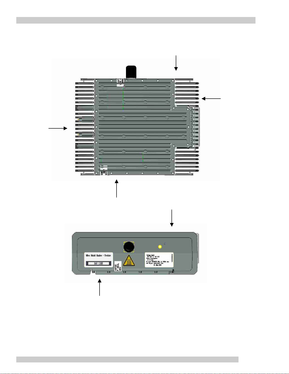
2.3.1 External View of the Transmitter Module
The physical external dimensions of the transmitter module are shown in the outline drawing in
Appendix A and Table 1. All inputs and outputs are also shown in the outline drawing
2.3.2 Connections and Mounting Hardware
The connections require a coaxial cable with an N-type (F-type optional for up to 10Watt unit)
male connector for the IF Input and waveguide CPR137F (flat)
mounted using up to four #10-32 threaded holes opposite the CPR137G RF output.
for RF output. The BUC is
Page 8 Rev 7

mitec Installation & Overview
2.4 Assembly and Installation
Use the information in this section as a guide to assemble and install the transmitter module.
CAUTION!
Only authorized technical personnel should perform the
installation and proper electrical hookups of the transmitter
module.
2.4.1 Lifting the Transmitter Module into Position and Temporary Attachment
The transmitter module weighs approximately 10 lbs (4.5 kg), which may be handled by a single
person. Remove all plastic caps from the connectors. Lift the transmitter module. The transmitter
module is now ready for permanent attachment.
2.4.2 Securing the Transmitter Module
Secure the transmitter module to the mounting frame using the hardware described in Section 2.3.2.
Attach the proper cable or waveguide for IF input and RF output to the corresponding connector of
the transmitter module. Refer to
the outline drawing in Appendix A.
NOTE
The connectors are labeled clearly and have different pin layout.
Refer to the outline drawing in Appendix A. It is impossible to
incorrectly install the mating connectors.
The BUC requires a steady flow of air. To provide a sufficient airflow, the BUC shall be properly
oriented, with the deepest heat sink fins facing up, and mounted with a minimum clearance of
3.0 inches on all sides of the BUC (see Figure 1). Adequate cooling for the BUC will provide
years of robust performance.
Rev 7 Page 9
Installation & Overview mitec
yp
Top View
IF Input NT
e
3 inches
3 inches
3 inches
min.
3 inches
min.
Tall heat sink fins
Pointing towards sky
CPRG137
3 inches
Cover pointing
towards ground
3 inches min.
Figure 1 – Recommended Distance for Mounting on the Hub
Page 10 Rev 7
Side View
mitec Installation & Overview
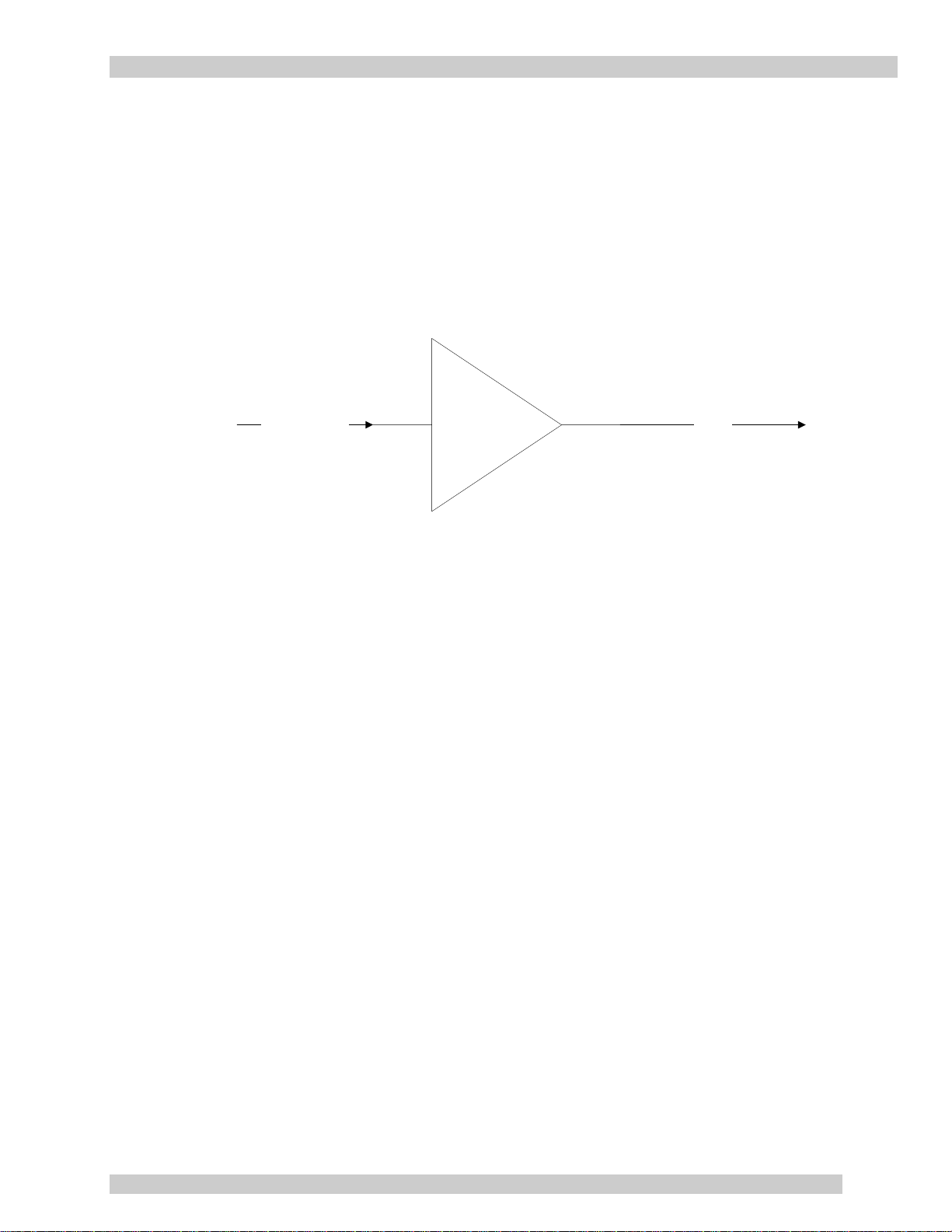
2.5 Functional Overview
2.5.1 General
This section describes the transmitter module functions in detail. The functional overview
explains the RF amplification, protection circuit and power distribution. The block diagram in
Figure 3 illustrates the transmitter module.
IF In
FSK
10MHz reference
(0 +/- 5 dBm)
+VDC
BUC
RF Out
Figure 2 – System Block Diagram
2.5.2 IF/RF Conversion and Amplification
The IF Input signal with a 10MHz reference, 0 ± 5dBm and +Vdc, enters the BUC by a coaxial
cable, is converted to C-Band by the BUC and goes through an isolator, which provides a good
VSWR at the input.
To achieve the rated output power, GaAs transistors, as well as other microwave components
within the RF Amplifier, provide the necessary gain and low insertion loss. The amplified signal
is transmitted through waveguide to a satellite up-link system.
2.5.3 Protection and Control
The transmitter has an optional FSK serial interface. All control and monitor signals are
translated within the micro-controller and then passed through the FSK serial interface.
The control system can provide the following M&C functions:
System Alarm: when an amplifier is not functioning properly.
Mute Control (via FSK) or disconnecting the 10MHZ input
Output power monitoring
Temperature Monitoring
Rev 7 Page 11

This page has been intentionally left blank.

mitec Operation
3 Operation
This Section describes the verification of the operation and control of the transmitter module. It
shall be performed by authorized personnel prior to maintenance and/or repair.
3.1 Procedure
Verify that the installation procedure described in Section 2 was completed. A complete physical
check of the customer’s system is suggested.
WARNING!
The output power available at the output waveguide flange is
extremely hazardous. Under no circumstances should the
transmitter be operated without the waveguide feed or a Low
Power load attached. Do not operate this equipment in the
presence of flammable gases or fumes. Failure to observe this
precaution will result in personal injury. Safe and careful
installation of this transmitter will eliminate the possibility of
accidents and provide years of robust performance.
Turn ON the power and allow a warm up period of twenty minutes before operating the
transmitter module. This will assure stable gain and power. The transmitter module can function
with a coupler when a direct measurement of the output power is made.
NOTE
The transmitter module can withstand any source or load VSWR.
However, the transmitter module will meet all specification
requirements only if the source/load VSWR is sufficient (see
Section 2.2).
NOTE
Normal operation is not possible if the antenna feeder VSWR is
greater than 1.5:1.
Rev 7 Page 13
 Loading...