

Page 1

User's manual
MSR-235 Burglar alarm
(Before using the unit, please read the instructions)
876 0MSR2353-04-
IV. Specifications:
1.Power : DC12V+/-20%
2.Standard Current : 30mA
3.Loading Current : 200mA Max.
4.Sound Level : 1M-110dB, 3M-100dB.
5.Battery Voltage : 6.0V/250mAh
6.Charging Current : 15mA
7.Strobe Current : 200mA
8.IP Standard : IP54
9.Tamperature : -20 ~+70
10.Dimension : 194(W)*300(H)*56.5(D)
11.Weight : 0.78kg
℃℃
mm
<
<
Page 2
5
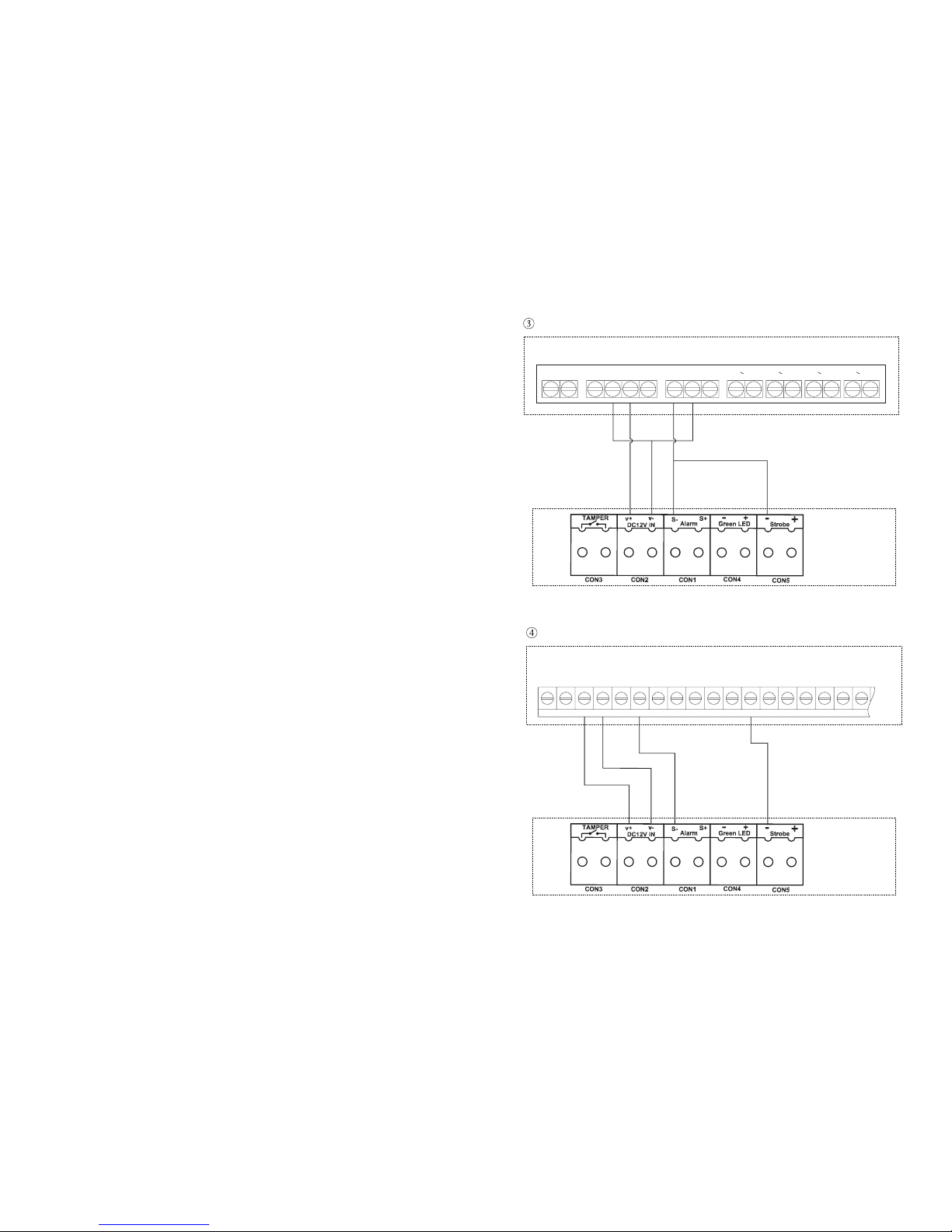
MAC-408 wiring diagram
--++
AC AC
NO COM NC
Z1 Z2 Z3 Z4
MAC-408
MSR-235
MSR-235
DSC PC-1616 & PC-1832 wiring diagram
Figure 7
AC
AUX
GRN
-
+
-
+
BELL
RED BLK YEL Z4Z3Z2
Z1
COM COM12
PGM
PC-1616 PC 1832&-
Figure 6
Page 3
I Features.
II. Function
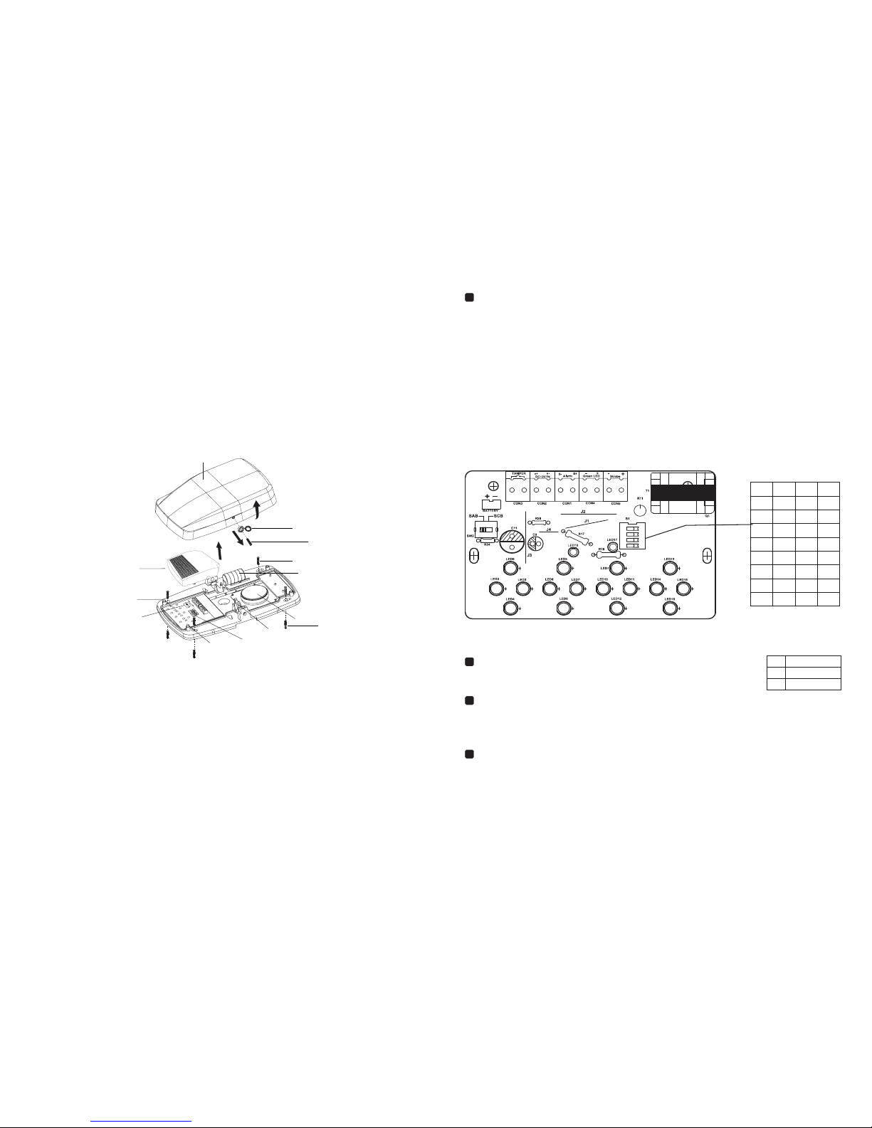
Main Board Connection
32
1. Cover
2. Screw cover
3. External Screw
(Security for Tamper Switch)
4. PCB Protection Cover
5. Red LED Indicator
6. Backup Battery
(Host line destroyed or cut,Sound an
alarm by the backup battery.)
7.SAB / SCB selector switch
Adjustable S1 encoder (Article 123) to set the alarm output
time.
Alarm output time setting (Table 1)
Delay settings (Table 2)
S1 adjust encoder (the forth code) sets the delay function ON / OFF
When the unit will delay 2 minutes on power before entering
the normal operation.
***
Figure 2
1
2
5
4
6
7
9
10
11
12
8
13
3
Figure 3
2
1
3
4
NO
[ ]
*
S1 Alarm time setting
Factory default: 14 minutes
*
12
3
OFF
OFFOFF
OFFOFF
OFFOFF
OFF OFF
OFFON
ON
Time
14m
8m
6m
2m
30s
5s
ON
ON
ONON
ON
ONONON
20m
Long
ring
OFF ON ON
OFF
()Table 1
Factory default: ON
*
4
Delay Mode
ON
OFF
Off Delay
S1 delay settings
()Table 2
SAB / SCB Mode
Sw2 choose SAB or SCB adjustment mode
SAB mode: When an alarm is triggered, the buzzer is powered by
the security console.
SCB mode: When an alarm is triggered, the buzzer is powered by
the built-in battery.
1. Working indicator : When the normal power supply and internal battery is connected
the red LED lights flashing.
2. Low-voltage alarm function: When the external power supply is lower than DC9.5V
or connect burglar hosts When wiring is cut, the unit automatically alert (from the
built-in battery-powered).
3. Two triggering alarm function, positive or negative trigger to match with different
trigger alarm host
4. A variety of alarm output timing (5-20 seconds, also choose a long ring)
5. The power-on delay function, when the power system latency two minutes before
entering the normal operation
8. Mounting Screw
9. Green LED
Indicator the System is ready
10. Set the alarm time encoder
11. Tamper switch
When moving the unit or unit is
moved from the wall, it will sound
an alarm.)
12. Buzzer
13. The expansion pipe
(
TAMPER tamper (NC), when the unit cover is opened or the chassis will trigger
TAPMER.
The positive power supply 12VDC (12V ~ 13.8V DC).
V - negative power 0V DC.
S - (ALARM) negative trigger.
S + (ALARM) positive trigger .
+ (Green LED) system indicates .
+ (Strobe) Flash positive trigger.
- (Strobe) Flash negative trigger.
V +
alarm
alarm
- (Green LED) system indicates .
2min delay
Page 4
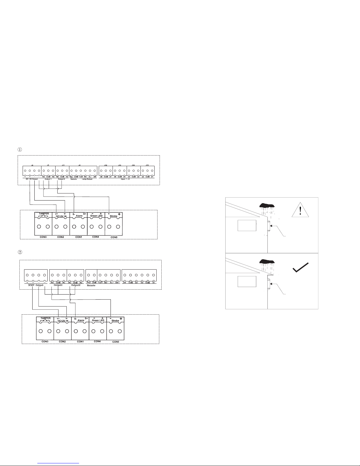
1. Dont exposed the unit in rain as shown below:
Warnning:
MSR- 200
¡I
MSR- 200
MSR-235
Figure 1
Caution:
1
MSR-235
2. wiring diagram.
III. Installation instructions
4
MAC-604 wiring diagram
Figure 4
MAC-608 wiring diagram
1. Refer to Figure 2 illustrates the open housing, in accordance with FIG
requires install the unit on the correct location.
Figure 5
CON1
CON2
CON3 CON4 CON5 CON6
MAC 6-04
MSR-235
MAC 6-08
MSR-235
2. To prevent electric shock, connect the power supply properly, do not
live installation.
3. When the unit is powered, do not contacts the electronic components
on the Pcb with hand or tool.
1. Only qualified personnel are allowed for installation.
2. Ensure that all the wires are properly connected before turning
the Power on.
3. Read this manual carefully and get familiar with the instruction
before operating.
4. After reading this manual,please keep it for future reference.
 Loading...