

Page 1
A
2
A
3
B
C
1
INSTALLING THE TANDEM KIT
For installation on copiers with a copy speed of 62 [A4 (lateral)] copies per minute
INSTALLATION DU KIT TANDEM
Pour une installation sur des copieurs avec une vitesse de copie de 62 [A4 (latéral)]
copies la minute
INSTALACION DEL KIT TANDEM
Para instalar en copiadoras con una velocidad de copiado de 62 [A4 (lateral)]
copias por minuto
D
E
F
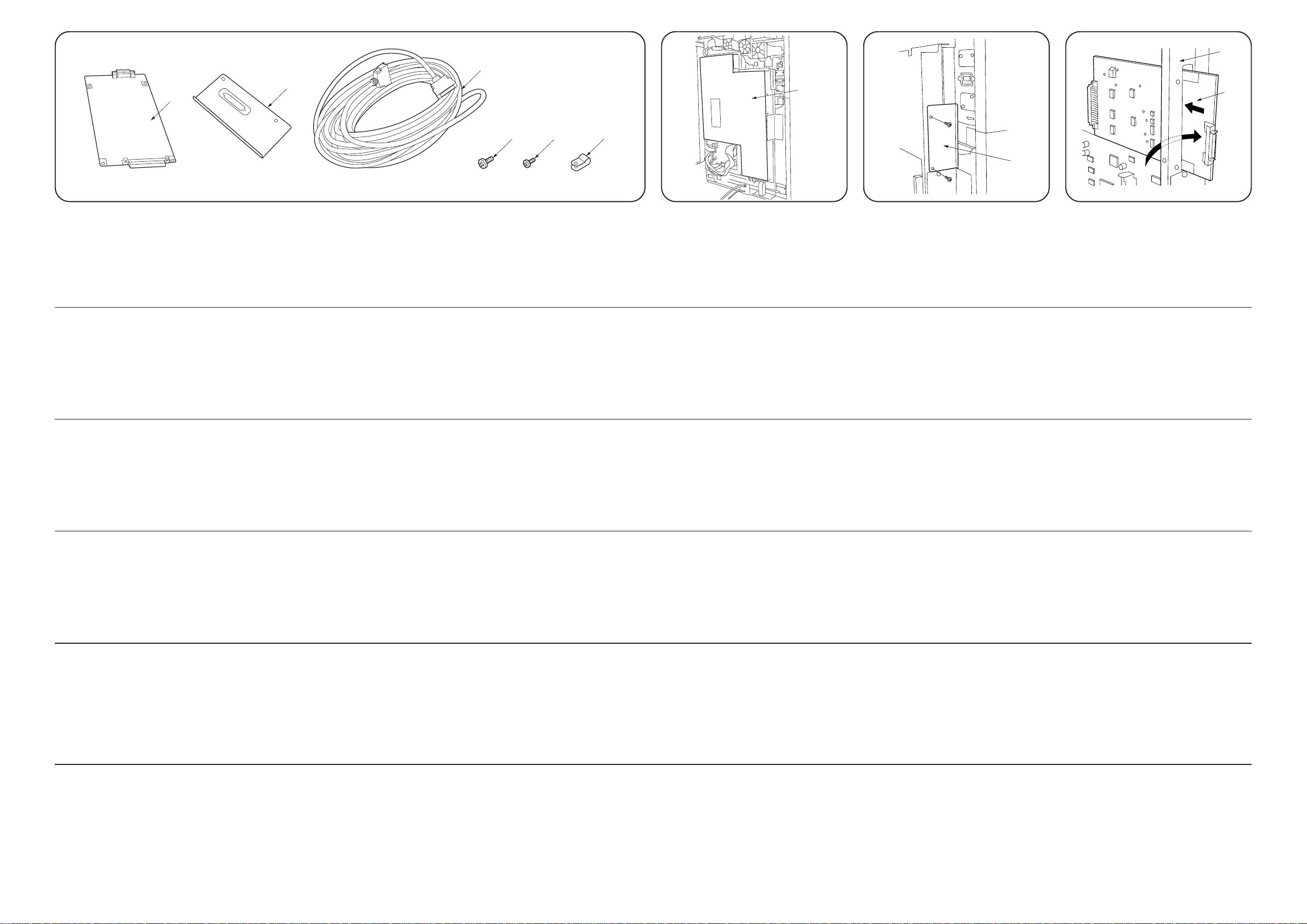
Supplied parts
A Interface PCB ....................................................... 2
B Interface OP cover ................................................ 2
C Interface cable ...................................................... 1
D M4 × 6 bronze binding screw ................................ 8
E M2.6 × 5 brass binding screw ............................... 4
F Clamp GNK-5N ..................................................... 2
(supplied for 230 V specs only)
Pièces fournis
A Carte de circuit imprimé d’interface ...................... 2
B Couvercle OP d’interface ...................................... 2
C Câble d’interface ................................................... 1
D Borne de raccordement en bronze M4 × 6 ........... 8
E Borne de raccordement en laiton M2.6 × 5........... 4
F Pince GNK-5N ...................................................... 2
(fournie pour spécifications de 230 V uniquement)
Partes suministradas
A PCB interfaz.......................................................... 2
B Cubierta OP interfaz ............................................. 2
C Cable interfaz ....................................................... 1
D Tornillo de fijación de bronce M4 × 6 ................... 8
E Tornillo de fijación de latón M2.6 × 5 .................... 4
F Abrazadera GNK-5N............................................. 2
(suministrada para especificaciones de 230 V
solamente)
Procedure
Note: This Tandem kit must be fitted to two
copiers. The following procedure details
installation onto one copier only.
1. Remove the six screws securing the rear
cover and then the cover from the copier.
2. Remove the fifteen screws securing the
main PCB cover 1 and then the cover 1.
Procédure
Remarque : ce kit Tandem doit être fixé à
1. Retirer les six vis qui fixent le couvercle
arrière puis retirer celui-ci du copieur.
2. Retirer les quinze vis qui fixent le couvercle
de la carte de circuit imprimé principale 1
puis retirer le couvercle 1.
deux copieurs. La procédure
suivante explique l’installation sur
un seul copieur.
Procedimiento
Nota: Este kit Tándem debe ser colocado en
dos copiadoras. El siguiente
procedimiento detalla la instalación en
una copiadora solamente.
1.
Quite los seis tornillos que aseguran la cubierta
posterior y luego la cubierta de la copiadora.
2. Quite los quince tornillos que aseguran la
cubierta del PCB principal 1 y luego la
cubierta 1.
3. Remove the two screws securing the interface cover 2 and then the cover 2.
3. Retirer les deux vis qui fixent le couvercle
de l’interface 2 puis retirer le couvercle 2.
3. Quite los dos tornillos que aseguran la
cubierta del interfaz 2 y luego la cubierta
2.
4. Insert an interface PCB A through the slot
in the main PCB shield 3 from the inside
(→).
4. Insérer une carte de circuit imprimé
d’interface A dans la rainure du bloc de la
carte de circuit imprimé principale 3 depuis
l’intérieur (→).
4. Inserte un PCB interfaz A a través de la
ranura ubicada en la cubierta protectora del
PCB principal 3 desde la parte interior (→).
INSTALLIEREN DES TANDEM-KITS
Für die Installation an Kopierern mit einer Kopiergeschwindigkeit von 62 [A4 (lateral)]
Kopien pro Minute
INSTALLAZIONE DEL KIT TANDEM
Per installazione su copiatrici con una velocità di copia di 62 copie al minuto
[A4 (laterale)]
Gelieferte Teile
A Schnittstellen-Leiterkarte ...................................... 2
B Schnittstellen-OP-Abdeckung ............................... 2
C Schnittstellenkabel ................................................ 1
D M4 × 6 bronzene Verbundschraube ..................... 8
E M2.6 × 5 Messing-Verbundschraube ................... 4
F Klemme GNK-5N .................................................. 2
(nur mit 230 V Spezifikation geliefert)
Parti fornite
A Scheda di interfaccia ............................................ 2
B Pannello OP di interfaccia .................................... 2
C Cavo di interfaccia ................................................ 1
D Vite di serraggio di bronzo M4 × 6 ........................ 8
E Vite di serraggio di ottone M2.6 × 5 ...................... 4
F Morsetto GNK-5N ................................................. 2
(fornito solo per specifiche da 230 V)
Vorgang
Hinweis: Dieses Tandem-Kit muß an zwei
1.
2.
Kopierer angebracht werden. Der
folgende Vorgang beschreibt nur die
Installation an einen Kopierer.
Entfernen Sie die sechs Schrauben, die die
hintere Abdeckung befestigen, und entfernen
Sie dann die hintere Abdeckung vom Kopierer.
Entfernen Sie die fünfzehn Schrauben, die die
Hauptleiterkarten-Abdeckung 1 befestigen
und dann die Hauptleiterkarten-Abdeckung 1.
Procedura
Nota: Questo kit tandem deve essere
collegato a due copiatrici. La procedura
seguente descrive in dettaglio
l’installazione su una sola copiatrice.
1. Rimuovere le sei viti che fissano il pannello
posteriore e quindi il pannello dalla
copiatrice.
2. Rimuovere le quindici viti che fissano il
pannello della scheda principale 1 e quindi
il pannello stesso 1.
3. Entfernen Sie die zwei Schrauben, die die
Schnittstellen-Abdeckung 2 befestigen und
dann die Schnittstellen-Abdeckung 2.
3. Rimuovere le due viti che fissano il pannello
dell’interfaccia 2 e quindi il pannello stesso
2.
4. Führen Sie von der Innenseite (→) eine
Schnittstellen-Leiterkarte A durch den
Schlitz im Hauptleiterkartenschutz 3.
4. Inserire una scheda di interfaccia A
attraverso lo slot nello schermo della
scheda principale 3 dall’interno (→).
2000. 7
3BS80010A
Page 2
D
7
8
F
5
CN1
A
D
B
4
CN2
D
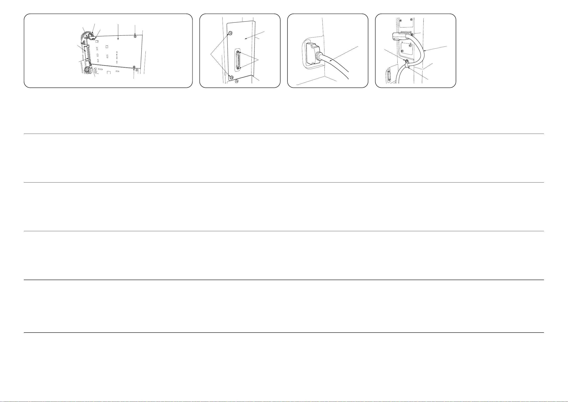
5. Insert CN2 on the interface PCB A into
connector CN2 4 on the main PCB of the
copier.
6. Secure the interface PCB A using four M4
× 6 bronze binding screws D.
5. Insérer CN2 se trouvant sur la carte de circuit imprimé d’interface A dans le
connecteur CN2 4 de la carte de circuit
imprimé principale du copieur.
6. Fixer la carte de circuit imprimé d’interface
A à l’aide de quatre bornes de
raccordement en bronze M4 × 6 D.
D
7. Insert the 2-pin connector on the S-BOX
wire 5 into 2-pin connector CN1 on the interface PCB A.
7. Insérer le connecteur à deux aiguilles du
câble S-BOX 5 dans le connecteur à deux
aiguilles CN1 de la carte de circuit imprimé
d’interface A.
6
E
8. Fit an interface OP cover B using the two
screws 6 removed in step 3.
9. Secure the connector of the interface PCB
A to the interface OP cover B using two
M2.6 × 5 brass binding screws E.
8. Fixer un couvercle OP d’interface B à l’aide
des deux vis 6 retirées à l’étape 3.
9. Fixer le connecteur de la carte de circuit
imprimé d’interface A au couvercle OP
d’interface B à l’aide de deux bornes de
raccordement en laiton M2.6 × 5 E.
C
10. Refit the main PCB cover and rear cover.
11. Connect the interface cable C to the
connector of the interface PCB A.
10. Refixer le couvercle de la carte de circuit
imprimé principale et le couvercle arrière.
11. Connecter le câble d’interface C au
connecteur de la carte de circuit imprimé
d’interface A.
For 230 V specifications only
If a saddle finisher is installed on the copier,
pass the signal cable 7 of the saddle finisher
through the clamp GNK-5N F and then
secure the clamp using a screw securing the
rear cover. (This is to satisfy the CE Marking requirements for noise prevention.)
Pour des spécifications de 230 V
uniquement
Si un retoucheur de chariot est installé sur le
copieur, faire passer le câble de signal 7 du
retoucheur de chariot dans la pince GNK-5N F
puis fixer la pince à l’aide d’une vis fixant le
couvercle arrière. (Par souci de conformite avec
les normes de la marque CE.)
5. Inserte el CN2 del PCB interfaz A en el
conector CN2 4 ubicado en el PCB principal de la copiadora.
6. Asegure el PCB interfaz A usando cuatro
tornillos de fijación de bronce M4 × 6 D.
5. Stecken Sie CN2 auf der SchnittstellenLeiterkarte A in den Steckverbinder CN2
4 auf der Hauptleiterkarte des Kopierers.
6. Sichern Sie die Schnittstellen-Leiterkarte A
mittels der vier bronzenen
Verbundschrauben D.
5. Inserire CN2 sulla scheda di interfaccia A
nel CN2 connettore 4 sulla scheda
principale della copiatrice.
6. Fissare la scheda di interfaccia A
utilizzando quattro viti di serraggio di bronzo
M4 × 6 D.
7. Inserte el conector de 2 pernos del cable SBOX 5 en el conector de 2 pernos CN1 del
PCB interfaz A.
7. Führen Sie den 2poligen Steckverbinder an
der S-BOX-Leitung 5 in den 2poligen
Steckverbinder CN1 auf der SchnittstellenLeiterkarte A ein.
7. Inserire il connettore a 2 pin sul cavo SBOX 5 nel connettore a 2 pin CN1 sulla
scheda di interfaccia A.
8. Coloque una cubierta OP interfaz B
usando los dos tornillos 6 removidos en el
paso 3.
9. Asegure el conector del interfaz PCB A en
la cubierta OP interfaz B usando dos tornillos de fijación de latón M2.6 × 5 E.
8. Bringen Sie mittels der zwei in Schritt 3
entfernten Schrauben 6 eine
Schnittstellen-OP-Abdeckung B an.
9. Bringen Sie mittels der zwei M2.6 × 5 Mess-
ing-Verbundschrauben E den
Steckverbinder auf der SchnittstellenLeiterkarte A sicher an die SchnittstellenOP-Abdeckung B an.
8. Inserire un pannello OP di interfaccia B
utilizzando le due viti 6 rimosse al punto 3.
9. Fissare il connettore della scheda di
interfaccia A al pannello OP di interfaccia
B utilizzando due viti di serraggio di ottone
M2.6 × 5 E.
10. Vuelva a colocar la cubierta del PCB
principal y la cubierta posterior.
11. Conecte el cable interfaz C en el
conector del PCB interfaz A.
10. Bringen Sie die HauptleiterkartenAbdeckung und hintere Abdeckung wieder
an.
11. Schliessen Sie das Schnittstellenkabel C
an den Steckverbinder der SchnittstellenLeiterkarte A an.
10. Reinserire il pannello della scheda
principale e il pannello posteriore.
11. Collegare il cavo di interfaccia C al
connettore della scheda di interfaccia A.
Para especificaciones de 230 V solamente
Si la copiadora tiene instalado un finalizador de
la placa, introduzca el cable de señal 7 del
finalizador de la plaza a través de la
abrazadera GNK-5N F y luego asegure la
abrazadera usando un tornillo que asegure la
cubierta posterior. (Esto se efectua para
satisfacer los requerimientos de la marca CE
para la prevencion del ruido.)
Nur für 230 V -Spezifikationen
Wenn ein Sattelfixierer am Kopierer installiert
ist, leiten Sie das Signalkabel 7 des
Sattelfixierers durch die Klemme GNK-5N F,
und sichern Sie dann die Klemme mittels einer
Schraube, die die hintere Abdeckung befestigt.
(Dieses gilt zur Sicherstellung der Vorschriften
der CE-Markierung zur Geräuschdämmung.)
Solo specifiche 230 V
Se una finitrice della slitta è installata sulla
copiatrice, far passare il cavo del segnale 7
della finitrice della slitta attraverso il morsetto
GNK-5N F e quindi fissare il morsetto
utilizzando una vite che fissi il pannello
posteriore (cio per soddisfare i requisiti del
segno CE sulla prevenzione dei rumori).
2000. 7
3BS80010A
Page 3

TANDEM COPY INSTRUCTION MANUAL
[Features]
• Jobs from scanners and computers can be equally assigned to two copiers for printing.
3) Press “Tandem copy”.
• If tandem operation should be halted due to a machine problem on one copier, the other
copier takes over the remaining work. Also, if tandem operation is interrupted because
one of the copiers is used for a different job, the copier that finishes its ongoing job first
helps with the remaining work of the other copier. (Output recovery function)
→Realization of total productivity improvement
• Interrupt operation is possible on the extension copier even when tandem operation is in
progress.
→Reduction of waiting time for urgent other jobs
[Operational specifications for tandem copying/printing]
• Copying is possible only in the sort mode.
• Jobs (preset number of copies) are equally assigned to the two copiers.
• Printing will not be performed while originals are being scanned or data transferred. It
starts only after scannng or data transfer is complete.
• Interrupt copying is not possible while originals are being scanned or data transferred
from a computer for tandem copying/printing (the operation panel will be locked).
• Once scanning or data transfer is complete and printing starts, interrupt operation is
possible only on the extension copier (a new job cannot be inserted on the main copier
until it finishes printing).
○○○○○
Main Sub
4) Set the copy mode on the main copier.
Note that in any of the situations given below, “Unable to Tandem Copy. Check Tandem
unit.*” appears on the display and the copier cannot be operated.
(* On European models, “CANNOT TANDEM COPY CHECK SLAVE MACHINE” will be
displayed.)
• Copy operation is in progress on the extension copier.
• The power of the extension copier is turned off.
• “Paper misfeed.”, “Call for service.” or “Add toner to resume copying” appears on the
display of the extension copier and copying is disabled on that copier.
5) Set the number of copies to be made on the main copier.
• To perform tandem copying, set the number of copies to two or higher.
• When the number of copies is set to an even number, the job is equally assigned to the
two copiers; when it is set to an odd number, the extra one copy is assigned to the main
copier.
1. Tandem copy operation procedure
1) Turn on the main switch on each of the two copiers connected using an interface cable.
2) Check that warm-up is complete.
6) Place originals on the main copier.
7) Press the Start key on the main copier.
2. If a problem occurs
• If copying is disabled on one of the copiers with any of “Paper misfeed.”, “Call for service.”
or “Add toner to resume copying” shown on the display, the other copier checks the
number of copies made by the disabled copier and takes over the remaining work.
• For details of the troubleshooting procedures for when “Paper misfeed.”, “Call for service.”
or “Add toner to resume copying” appears on the display, see the instruction handbook of
the copier.
• The copier that has halted will resume the interrupted copying operation when the problem
is remedied.
2000. 7
3BS80020A
 Loading...