

Page 1

STDF-3
Page 2

CONTENTS
1-1 Specifications
1-1-1 Specifications ....................................................................................................................................... 1-1-1
1-1-2 Part names and their functions ............................................................................................................ 1-1-2
1-1-3 Machine cross section .......................................................................................................................... 1-1-3
1-1-4 Drive system ........................................................................................................................................ 1-1-4
1-2 Installation
1-2-1 Unpacking ............................................................................................................................................ 1-2-1
1-3 Troubleshooting
1-3-1 Original misfeed detection .................................................................................................................... 1-3-1
(1) Original misfeed indication ............................................................................................................ 1-3-1
(2) Original misfeed detection condition ............................................................................................. 1-3-2
(3) Original misfeeds .......................................................................................................................... 1-3-3
(1) An original jams when the main switch is turned on. ............................................................. 1-3-3
(2) An original jams during continuous copying of multiple originals. ......................................... 1-3-3
(3) An original jams in the DF during copying (no original feed). ................................................ 1-3-3
(4) An original jams in the DF during copying (an original jam in the original feed
and conveying sections). ....................................................................................................... 1-3-3
(5) Original jams frequently. ........................................................................................................ 1-3-3
1-3-2 Image formation problems ................................................................................................................... 1-3-4
(1) There is a regular error between the centers of the original and copy image
when the DF is used. .................................................................................................................... 1-3-5
(2) There is a regular error between the leading edges of the original and copy image
when the DF is used. .................................................................................................................... 1-3-5
1-3-3 Electrical problems ............................................................................................................................... 1-3-6
(1) The original feed motor does not operate. .................................................................................... 1-3-6
(2) The original conveying motor does not operate. ........................................................................... 1-3-6
(3) The copier scans the contact glass when originals are loaded on the DF. ................................... 1-3-6
(4) An original jams when the main switch is turned on. .................................................................... 1-3-6
1-3-4 Mechanical problems ........................................................................................................................... 1-3-7
(1) No primary original feed. ............................................................................................................... 1-3-7
(2) No secondary original feed. .......................................................................................................... 1-3-7
(3) Originals jam. ................................................................................................................................ 1-3-7
3A7
1-4 Assembly and Disassembly
1-4-1 Precautions for assembly and disassembly ......................................................................................... 1-4-1
(1) Precautions ................................................................................................................................... 1-4-1
1-4-2 Procedure for assembly and disassembly ........................................................................................... 1-4-2
(1) Detaching and refitting the DF forwarding pulley and DF original feed pulley .............................. 1-4-2
(2) Detaching and refitting the DF separation pulley .......................................................................... 1-4-3
(3) Adjusting the lateral squareness of the DF ................................................................................... 1-4-4
(4) Adjusting the DF magnification ..................................................................................................... 1-4-5
(5) Adjusting the DF center line .......................................................................................................... 1-4-7
(6) Adjusting the scanning start position when the DF is used ........................................................... 1-4-9
(6-1) Adjusting the DF leading edge registration .......................................................................... 1-4-9
(6-2) Adjusting the DF trailing edge registration ......................................................................... 1-4-11
(7) Adjusting the margins for scanning the original from the DF ...................................................... 1-4-13
2-1 Mechanical construction
2-1-1 Mechanical construction ....................................................................................................................... 2-1-1
(1) Original feed mechanism .............................................................................................................. 2-1-1
(2) Original feed timing ....................................................................................................................... 2-1-3
1-1-1
2-2 Electrical Parts Layout
2-2-2 Electrical parts layout ........................................................................................................................... 2-2-1
Page 3

3A7
2-3 Operation of the PCBs
2-3-1 DF driver PCB ...................................................................................................................................... 2-3-1
2-3-2 Original size detection PCB ................................................................................................................. 2-3-4
2-4 Appendixes
Timing chart No. 1 .......................................................................................................................................... 2-4-1
Timing chart No. 2 .......................................................................................................................................... 2-4-2
Periodic maintenance procedures .................................................................................................................. 2-4-3
Wiring diagram ............................................................................................................................................... 2-4-4
1-1-2
Page 4

1-1-1 Specifications
3A7
Original feed system ...................... Automatic feed
Originals ......................................... Sheets
Original weights.............................. 35 – 160 g/m
2
Original sizes .................................. A3 – A5R, folio/11" × 17" – 51/2" × 81/2"
Number of originals ........................ Up to 70 sheets (A4 or smaller paper of 80 g/m
2
75 g/m
)
Up to 50 sheets (B4, folio or larger paper of 80 g/m
2
75 g/m
)
Up to 30 sheets in the auto selection mode
Thermal and art paper must be fed individually.
Power source ................................. Electrically connected to the copier
Machine dimensions ...................... 553 (W) × 478 (D) × 121 (H) mm
3
/4" (W) × 1813/16" (D) × 43/4" (H)
21
Weight ............................................Approx. 6.9 kg/15.18 lbs
2
, or 11" × 81/2" or smaller paper of
2
, or 81/2" × 14" or larger paper of
1-1
1-1-1
Page 5

3A7
4
1-1-2 Part names and their functions
1-1
5
3
Figure 1-1-1
1 Original table
2 Original insertion guides
3 DF open/close handle
4 Original eject cover
5 DF original cover
2
1
1-1-2
Page 6

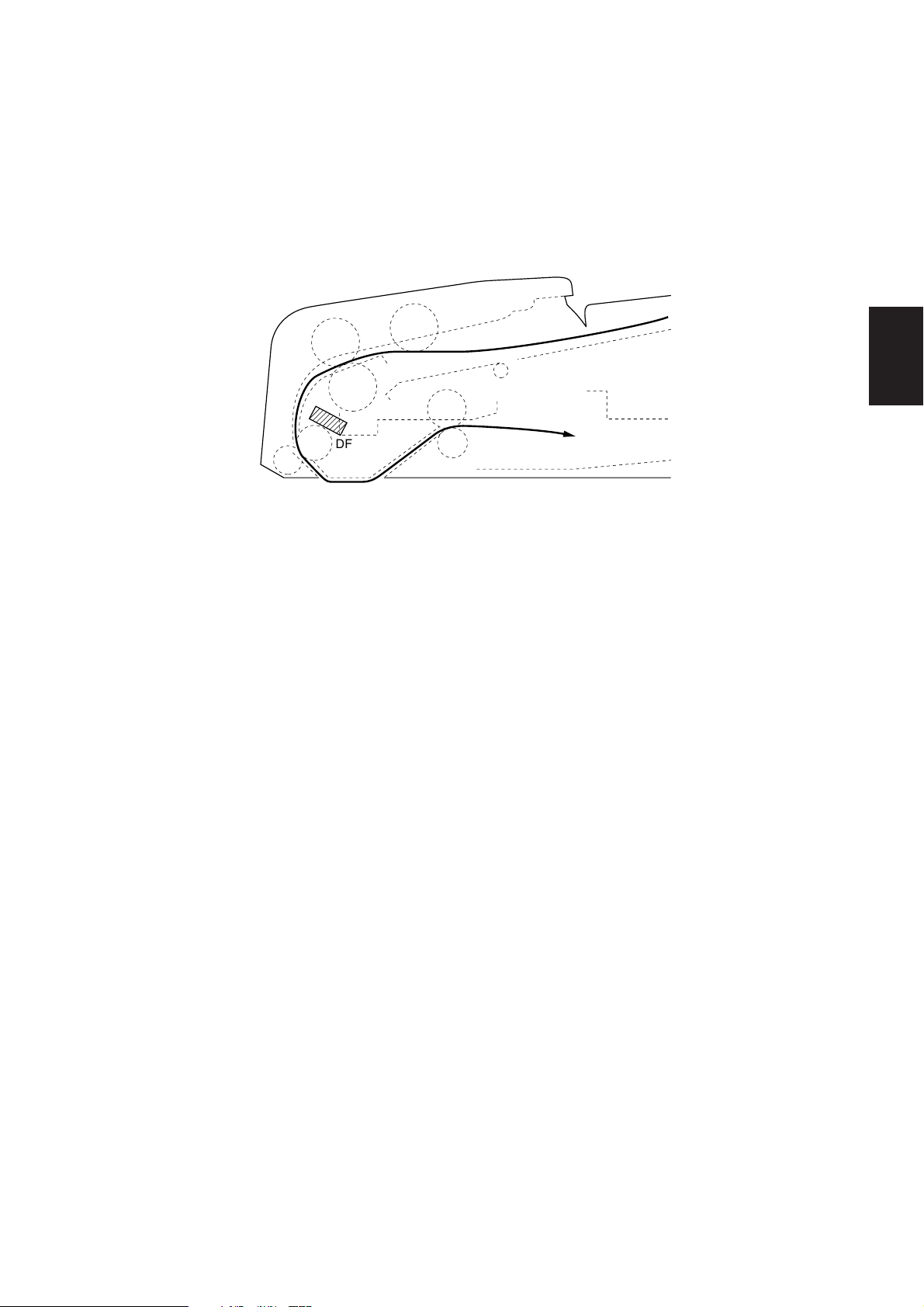
1-1-3 Machine cross section
3A7
1-1
Original path
Figure 1-1-2 Machine cross section
1-1-3
Page 7

3A7
1-1-4 Drive system
1-1
@
!
5
6
7
2
0
9
4
#
$
1 Original feed motor gear
2 Gear 42/29
3 Lift gear 38
4 Idle gear 20
5 Original feed gear 30
6 Original feed pulley
7 Forwarding belt
8 Forwarding pulley 20
9 Original conveying motor gear
^
8
3
1
&
%
Figure 1-1-3
0 Idle gear Z45/B16
! Original conveying belt 92
@ Tension pulley
# Registration pulley 19
$ Original conveying pulley 24
% Original conveying belt 190
^ Tension pulley
& Original conveying pulley 24
1-1-4
Page 8
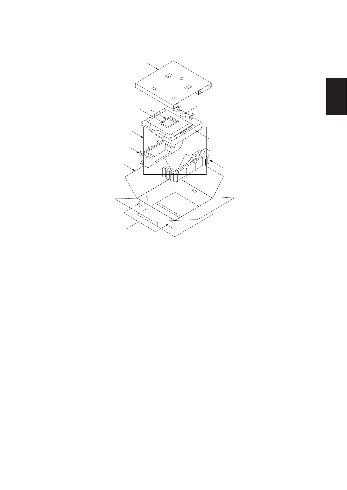
1-2-1 Unpacking
6
4
7
2
5
3
3A7
1-2
9
1
4
8
Figure 1-2-1 Unpacking
1 Sheet through DF
2 Installation manual
3 Plastic bag
4 Bottom pads
5 Upper pad
6 Outer case
7 Plastic sheet
8 Bar-code labels
9 Plastic bag
1-2-1
Page 9
3A7
1-3-1 Original misfeed detection
(1) Original misfeed indication
When an original jams, the machine immediately stops operation and the occurrence of an original jam is indicated on the
copier operation panel.
To remove the jammed original, open the DF or the DF original cover.
To reset the original misfeed detection, open and close the DF or the DF original cover to turn DF safety switch 1 or 2 off and
on.
DFTSW
Figure 1-3-1 Original misfeed detection
1-3
1-3-1
Page 10

3A7
(2) Original misfeed detection condition
• No original feed (jam code 70)
During the primary feed of the second or later original, the DF timing switch (DFTSW) does not turn on within 1410 original
feed motor (OFM) pulses of the start of forward rotation of the original feed motor (OFM). After up to five retries, the DF
timing switch (DFTSW) still fails to turn on.
1-3
OFM
DFTSW
1410 P*
* Burst of OFM pulses
Off
On (Fwd.)
Off
On
Timing chart 1-3-1
• An original jam in the original feed and conveying sections (jam code 73)
During the secondary original feed, the DF timing switch (DFTSW) does not turn off within 10200 original conveying motor
(OCM) pulses of the DF timing switch (DFTSW) turning on.
DFTSW
10200 P*
* Burst of OCM pulses
Off
On
Timing chart 1-3-2
During the secondary original feed, the DF timing switch (DFTSW) turns off within 1764 original conveying motor (OCM)
pulses of the DF timing switch (DFTSW) turning on.
DFTSW
1764 P*
* Burst of OCM pulses
Off
On
Timing chart 1-3-3
1-3-2
Page 11

(3) Original misfeeds
Problem Causes Check procedures/corrective measures
(1)
An original jams
when the main
switch is turned on.
A piece of paper torn from
an original is caught around
the actuator of the original
size detection PCB.
Defective original size
detection PCB.
Remove any found.
With 5 V DC present at CN5-8 on the DF driver PCB, check if
CN5-3 on the DF driver PCB remains low when the actuator on
the machine front side of the original size detection PCB is turned
on and off. If it does, replace the original size detection PCB.
3A7
(2)
An original jams
during continuous
copying of multiple
originals.
(3)
An original jams in
the DF during
copying (no original
feed).
A piece of paper torn from
an original is caught around
the DF timing switch.
Defective DF timing switch.
Defective original size
detection PCB.
Check if the original feed
motor or original conveying
motor is malfunctioning.
Defective DF timing switch.
Check if the original feed
motor is malfunctioning.
Check if the DF forwarding
pulley, DF original feed
pulley or DF separation
pulley is deformed.
Remove any found.
1-3
With 5 V DC present at CN5-8 on the DF driver PCB, check if
CN5-1 on the DF driver PCB remains low when the DF timing
switch is turned on and off. If it does, replace the DF timing
switch.
With 5 V DC present at CN5-8 on the DF driver PCB, check if
CN5-3 on the DF driver PCB remains low when the actuator on
the machine front side of the original size detection PCB is turned
on and off. If it does, replace the original size detection PCB.
Check and remedy.
With 5 V DC present at CN5-8 on the DF driver PCB, check if
CN5-1 on the DF driver PCB remains high when the DF timing
switch is turned on and off. If it does, replace the DF timing
switch.
Check and remedy.
Check visually and replace the pulley if deformed (see pages
1-4-2 and 3).
(4)
An original jams in
the DF during
copying (an original
jam in the original
feed and conveying
sections).
(5)
Original jams
frequently.
Defective DF timing switch.
Check if the DF forwarding
pulley, DF original feed
pulley or DF separation
pulley is deformed.
Check if the upper or lower
DF registration roller is
deformed.
An original outside the
specifications is used.
The DF forwarding pulley,
DF original feed pulley or
DF separation pulley is
soiled with paper powder.
The DF original feed pulley
and DF separation pulley
do not contact correctly.
With 5 V DC present at CN5-8 on the DF driver PCB, check if
CN5-1 on the DF driver PCB remains high or low when the DF
timing switch is turned on and off. If it does, replace the DF timing
switch.
Check visually and replace the pulley if deformed (see pages
1-4-2 and 3).
Check visually and replace the roller if deformed.
Use only originals conforming to the specifications.
Clean with isopropyl alcohol.
Remedy.
1-3-3
Page 12

3A7
1-3-2 Image formation problems
1-3
(1) There is a regular error
between the centers of
the original and copy
image when the DF is
used.
See page 1-3-5.
(2) There is a regular error
between the leading
edges of the original
and copy image when
the DF is used.
See page 1-3-5.
1-3-4
Page 13
3A7
(1) There is a regular error
between the centers of
the original and copy
image when the DF is
used.
Causes
1. Misadjusted DF center line.
(2) There is a regular error
between the leading
edges of the original
and copy image when
the DF is used.
Causes
1. Misadjusted DF center line.
Check procedures/corrective measures
Readjust the DF center line (see page 1-4-7).
Causes
1. Misadjusted DF original scanning start position.
1-3
Causes
1. Misadjusted DF original scanning start
position.
Check procedures/corrective measures
Readjust the DF original scanning start position (see page 1-4-9).
1-3-5
Page 14

3A7
1-3-3 Electrical problems
Problem Causes Check procedures/corrective measures
(1)
The original feed
motor does not
operate.
Broken original feed motor
coil.
The connector terminals of
the original feed motor
make poor contact.
Check for continuity across the coil. If none, replace the original
feed motor.
Reinsert the connector. Also check for continuity within the
connector cable. If none, remedy or replace the cable.
1-3
(2)
The original
conveying motor
does not operate.
(3)
The copier scans the
contact glass when
originals are loaded
on the DF.
(4)
An original jams
when the main
switch is turned on.
Defective DF driver PCB.
Broken original conveying
motor coil.
The connector terminals of
the original conveying
motor make poor contact.
Defective DF driver PCB.
The connector terminals of
DF safety switch 1 make
poor contact.
Defective DF safety
switch 1.
Defective original size
detection PCB.
A piece of paper torn from
an original is caught around
the actuator of the original
size detection PCB.
Defective original size
detection PCB.
Check for continuity across the coil and connector terminals of
the original feed motor. If present, replace the DF driver PCB.
Check for continuity across the coil. If none, replace the original
conveying motor.
Reinsert the connector. Also check for continuity within the
connector cable. If none, remedy or replace the cable.
Check for continuity across the coil and connector terminals of
the original conveying motor. If present, replace the DF driver
PCB.
Reinsert the connector. Also check for continuity within the
connector cable. If none, remedy or replace the cable.
Check for continuity across the contacts of DF safety switch 1. If
none when the switch is on, replace DF safety switch 1.
With 5 V DC present at CN5-8 on the DF driver PCB, check if
CN5-3 on the DF driver PCB remains high when the actuator on
the machine front side of the original size detection PCB is turned
on and off. If it does, replace the original size detection PCB.
Remove any found.
With 5 V DC present at CN5-8 on the DF driver PCB, check if
CN5-3 on the DF driver PCB remains low when the actuator on
the machine front side of the original size detection PCB is turned
on and off. If it does, replace the original size detection PCB.
1-3-6
A piece of paper torn from
an original is caught around
the DF timing switch.
Defective DF timing switch.
Remove any found.
With 5 V DC present at CN5-8 on the DF driver PCB, check if
CN5-1 on the DF driver PCB remains low when the DF timing
switch is turned on and off. If it does, replace the DF timing
switch.
Page 15

1-3-4 Mechanical problems
Problem Causes/check procedures Corrective measures
(1)
No primary original feed.
The surfaces of the DF forwarding pulley, DF
original feed pulley or DF separation pulley
are soiled with paper powder.
3A7
Check and clean them with isopropyl
alcohol if they are soiled.
(2)
No secondary original
feed.
(3)
Originals jam.
Check if the DF forwarding pulley, DF original
feed pulley or DF separation pulley is
deformed.
Electrical problem with the original feed
motor.
The upper and lower DF registration rollers
do not contact each other correctly.
Electrical problem with the original conveying
motor.
Originals outside the specifications are used.
The surfaces of the DF forwarding pulley, DF
original feed pulley or DF separation pulley
are soiled with paper powder.
The DF original feed pulley and DF
separation pulley, or the upper and lower DF
eject roller do not contact each other
correctly.
Check visually and replace the deformed
pulley (see pages 1-4-2 and 3).
See page 1-3-6.
Remedy.
1-3
See page 1-3-6.
Use only originals conforming to the
specifications.
Check and clean them with isopropyl
alcohol if they are soiled.
Remedy.
1-3-7
Page 16

1-4-1 Precautions for assembly and disassembly
(1) Precautions
• Be sure to turn the main switch off and disconnect the power plug before starting disassembly.
• When handling PCBs, do not touch connectors with bare hands or damage the board.
• Do not touch any PCB containing ICs with bare hands or any object prone to static charge.
• Use the following testers when measuring voltages:
Hioki 3200
Sanwa MD-180C
Sanwa YX-360TR
Beckman TECH300
Beckman DM45
Beckman 330*
Beckman 3030*
Beckman DM850*
Fluke 8060A*
Arlec DMM1050
Arlec YF1030C
* Capable of measuring RMS values.
• Prepare the following as test originals:
1. NTC (new test chart)
2. NPTC (newspaper test chart)
3A7
1-4
1-4-1
Page 17

1-4
3A7
1-4-2 Procedure for assembly and disassembly
(1) Detaching and refitting the DF forwarding pulley and DF original feed pulley
Clean or replace the DF forwarding pulley and DF original feed pulley as follows.
Procedure
1. Open the DF original cover.
2. Remove the original feed pulley guide.
Original feed
pulley guide
Figure 1-4-1
• Detaching the DF forwarding pulley
3. Remove the stop ring at the machine front.
4. Pull the forwarding shaft out and remove
the DF forwarding pulley.
• Detaching the DF original feed pulley
5. Remove the stop ring at the machine front and
remove the bushing.
6. Pull the original feed shaft toward the machine
rear and shift the rear bushing toward the
machine rear.
7. Remove the DF original feed pulley.
8. Clean or replace the DF forwarding pulley and
DF original feed pulley.
9. Refit all the removed parts.
Stop ring
Stop ring
Bushing
DF forwarding pulley
Figure 1-4-2
DF original feed pulley
Original feed shaft
Forwarding shaft
Bushing
1-4-2
Figure 1-4-3
Page 18

(2) Detaching and refitting the DF separation pulley
Clean or replace the DF separation pulley as follows.
Procedure
1. Open the DF original cover.
2. Remove the screw securing the original feed
guide and then the guide.
3A7
Original feed guide
Figure 1-4-4
3. Remove the stop ring, pull the separation shaft
out and remove the DF separation pulley.
4. Clean or replace the DF separation pulley.
5. Refit all the removed parts.
Stop ring
Figure 1-4-5
1-4
DF separation
pulley
Separation shaft
1-4-3
Page 19

3A7
(3) Adjusting the lateral squareness of the DF
Perform the following adjustment if the leading edge or trailing edge of the copy image is laterally skewed (lateral
squareness not obtained).
Caution:
Before adjusting the lateral squareness of the DF, adjust the amount of slack in the paper at the registration roller and
scanner image lateral squareness at the copier first and check the lateral squareness of the copy image by copying using
the DF. If squareness is still not obtained, perform the following adjustment.
Procedure
Start
Place an original on the DF
and make a test copy.
1-4
Is the image correct?
Yes
End
No
Remove the three screws and DF
lower front cover. See Figure 1-4-7.
Loosen the two screws and adjust the
position of the original feed unit using
the center of the scale as the reference.
See Figure 1-4-7.
¥ For copy example 1, turn the
adjustment pin and move the original
feed unit toward the machine left (b).
¥ For copy example 2, turn the
adjustment pin and move the original
feed unit toward the machine right (e).
Tighten the two screws.
Refit the DF lower front cover.
Original Copy
example 1
Figure 1-4-6
Copy
example 2
1-4-4
Adjustment pin
DF lower
front cover
Screws
Original feed unit
Figure 1-4-7
Page 20

(4) Adjusting the DF magnification
Adjust magnification in the auxiliary scanning direction if magnification is incorrect when the DF is used.
3A7
U053
U034
U403
U402 U066
U070
U065
U071
(P. 1-4-9)
U404
(P. 1-4-13)
Caution:
Before making the following adjustment, ensure that the above adjustments have been made in maintenance mode.
Procedure
• 20 cpm copier
Enter maintenance mode.
Press the interrupt key.
Place an original on the DF
and make a test copy.
Start
Auxiliary
scanning
direction
Enter “070” using
the numeric keys.
Press the start key.
Press the start key.
The new setting is stored.
Main scanning
direction
Original
Figure 1-4-8
Copy
example 1
Copy
example 2
1-4
Is the image correct?
Yes
Press the stop/clear key.
Exit maintenance mode.
End
No
Change the setting using the
cursor left/right keys.
• For copy example 1, increase
the value to make the copy
image longer.
• For copy example 2, decrease
the value to make the copy
image shorter.
Setting range: –25 to +25
Changing the value by 1 changes
the magnification by 0.1%.
Reference: 0
1-4-5
Page 21

3A7
• 15 cpm copier
Enter maintenance mode.
Start
Enter “070” using
the numeric keys.
Press the start key.
Auxiliary
scanning
direction
Main scanning
direction
Original
Figure 1-4-9
Copy
example 1
Copy
example 2
1-4
Press the interrupt key.
Place an original on the DF
and make a test copy.
Is the image correct?
Yes
Press the stop/clear key.
Exit maintenance mode.
End
No
Press the start key.
The new setting is stored.
Change the setting using the
zoom +/– keys.
• For copy example 1, increase
the value to make the copy
image longer.
• For copy example 2, decrease
the value to make the copy
image shorter.
Setting range: –25 to +25
Changing the value by 1 changes
the magnification by 0.1%.
Reference: 0
1-4-6
Page 22

3A7
(5) Adjusting the DF center line
Perform the following adjustment if there is a regular error between the centers of the original and the copy image when the
DF is used.
U034
U402
U067 U072U403
U404
(P. 1-4-13)
Caution:
Before making the following adjustment, ensure that the above adjustments have been made in maintenance mode.
Procedure
• 20 cpm copier
Start
Enter maintenance mode.
Enter “072” using the numeric
keys and press the start key.
Press the interrupt key.
Place an original on the DF
and make a test copy.
Is the image correct?
Yes
Press the stop/clear key.
Exit maintenance mode.
Press the start key.
Change the setting using the
cursor left/right keys.
No
• For copy example 1, increase
the value.
• For copy example 2, decrease
the value.
Setting range: –39 to +39
Changing the value by 1 moves the center line
by 0.17 mm.
Reference: 0
Reference
Original Copy
The new setting
is stored.
example 1
Figure 1-4-10
Copy
example 2
1-4
End
1-4-7
Page 23

3A7
• 15 cpm copier
1-4
Start
Enter maintenance mode.
Enter “072” using the numeric
keys and press the start key.
Press the interrupt key.
Place an original on the DF
and make a test copy.
Is the image correct?
Yes
Press the stop/clear key.
Exit maintenance mode.
Reference
Original Copy
Press the start key.
The new setting
is stored.
Change the setting using the
zoom +/– keys.
No
• For copy example 1, increase
the value.
• For copy example 2, decrease
the value.
Setting range: –39 to +39
Changing the value by 1 moves the center line
by 0.17 mm.
Reference: 0
example 1
Figure 1-4-11
Copy
example 2
End
1-4-8
Page 24

3A7
(6) Adjusting the scanning start position when the DF is used
Perform the following adjustment if there is a regular error between the leading or trailing edges of the original and the copy
image.
U034
U402
U066 U071U403
U404
(P. 1-4-13)
Caution:
Before making the following adjustment, ensure that the above adjustments have been made in maintenance mode.
(6-1) Adjusting the DF leading edge registration
Procedure
• 20 cpm copier
Start
Enter maintenance mode.
Enter “071” using the numeric
keys and press the start key.
Original
Copy
example 1
Copy
example 2
Figure 1-4-12
Select “LEAD EDGE ADJ”
using the cursor up/down
keys.
Press the interrupt key.
Press the start key.
The new setting is stored.
1-4
Place an original on the
DF and make a test copy.
Is the image correct?
Yes
Press the stop/clear key.
Exit maintenance mode.
End
No
• For copy example 1,
increase the value using
the cursor right key.
• For copy example 2,
decrease the value using
the cursor left key.
Setting range: –32 to +32
Reference: 0
Changing the value by 1 moves
the copy image by 0.19 mm.
Increasing the value moves the copy
image backward, and decreasing it
moves the image forward.
1-4-9
Page 25

3A7
• 15 cpm copier
Enter maintenance mode.
Start
1-4
Enter “071” using the numeric
keys and press the start key.
Light the copy exposure indicator
exp. 1 using the copy exposure
adjustment keys.
Press the interrupt key.
Place an original on the
DF and make a test copy.
Is the image correct?
Yes
Press the stop/clear key.
Exit maintenance mode.
End
No
Original
Press the start key.
The new setting is stored.
• For copy example 1,
increase the value using
the zoom + key.
• For copy example 2,
decrease the value using
the zoom – key.
Setting range: –32 to +32
Reference: 0
Changing the value by 1 moves
the copy image by 0.19 mm.
Increasing the value moves the copy
image backward, and decreasing it
moves the image forward.
Copy
example 1
Figure 1-4-13
Copy
example 2
1-4-10
Page 26

(6-2) Adjusting the DF trailing edge registration
Perform the following adjustment if the original scanning end position is not correct.
Caution:
If the copies look like copy example 2, clean the DF original scanning section.
Procedure
• 20 cpm copier
Start
Enter maintenance mode.
Enter “071” using the numeric
keys and press the start key.
Select “TRAIL EDGE ADJ”
using the cursor up/down
keys.
Press the interrupt key.
Place an original on the DF
and make a test copy.
Press the start key.
The new setting is stored.
Original Copy
example 1
Figure 1-4-14
3A7
Copy
example 2
1-4
Is the image correct?
Yes
Press the stop/clear key.
Exit maintenance mode.
End
• For copy example 1,
No
increase the value using
the cursor right key.
• For copy example 2,
decrease the value using
the cursor left key.
Setting range: –32 to +32
Reference: 0
Changing the value by 1 moves
the copy image by 0.19 mm.
Increasing the value moves the trailing
edge of the copy image backward,
and decreasing it moves the trailing
edge of the image forward.
1-4-11
Page 27

3A7
• 15 cpm copier
Enter maintenance mode.
Enter “071” using the numeric
keys and press the start key.
Light the copy exposure indicator
exp. 2 using the copy exposure
adjustment keys.
Start
Original Copy
example 1
Figure 1-4-15
Copy
example 2
1-4
Press the interrupt key.
Place an original on the DF
and make a test copy.
Is the image correct?
Yes
Press the stop/clear key.
Exit maintenance mode.
End
Press the start key.
The new setting is stored.
• For copy example 1,
No
increase the value using
the zoom + key.
• For copy example 2,
decrease the value using
the zoom – key.
Setting range: –32 to +32
Reference: 0
Changing the value by 1 moves
the copy image by 0.19 mm.
Increasing the value moves the trailing
edge of the copy image backward,
and decreasing it moves the trailing
edge of the image forward.
1-4-12
Page 28

(7) Adjusting the margins for scanning the original from the DF
Perform the following adjustment if margins are not correct.
3A7
U402 U404
U403
Caution:
Before making the following adjustment, ensure that the above adjustments have been made in maintenance mode.
Procedure
• 20 cpm copier
Start
Enter maintenance mode.
Enter “404” using the numeric keys.
Press the start key.
Adjustment items
Select the item to be adjusted
using the cursor up/down keys.
Press the interrupt key.
A MGN: DF left margin
B MGN: DF leading edge margin
C MGN: DF right margin
D MGN: DF trailing edge margin
Press the start key.
The new setting is stored.
1-4
Yes
Place an original on the DF
and make a test copy.
Are the margins correct?
Yes
Proceed to another mode?
No
Press the stop/clear key.
Exit maintenance mode.
End
No
Change the setting.
• Increasing the value using the
cursor right key makes the
margin wider.
• Decreasing the value using the
cursor left key makes the
margin narrower.
Setting range (default)
DF left margin: 0.0 to 10.0 (2)
DF leading edge margin: 0.0 to 10.0 (3)
DF right margin: 0.0 to 10.0 (2)
DF trailing edge margin: 0.0 to 10.0 (2)
Changing the value by 1 moves
the margin by 0.5 mm for all.
Ejection direction
(reference)
DF left margin
+1.5
(2.5
mm)
–2.0
DF leading edge margin (3 ± 2.5 mm)
DF right margin
+1.5
mm)
(2.5
–2.0
DF trailing edge margin
(3 ± 2.5 mm)
Figure 1-4-16
1-4-13
Page 29

3A7
• 15 cpm copier
Enter maintenance mode.
Enter “404” using the numeric keys.
Select the item to be adjusted using
the copy exposure adjustment keys.
Start
Press the start key.
Adjustment items (copy exposure indicator)
Exp. 1: DF left margin
Exp. 2: DF leading edge margin
Exp. 3: DF right margin
Exp. 4: DF trailing edge margin
1-4
Yes
Press the interrupt key.
Place an original on the DF
and make a test copy.
Are the margins correct?
Yes
Proceed to another mode?
No
Press the stop/clear key.
Exit maintenance mode.
End
No
Press the start key.
The new setting is stored.
Change the setting.
• Increasing the value using the
zoom + key makes the margin
wider.
• Decreasing the value using the
zoom – key makes the margin
narrower.
Setting range (default)
DF left margin: 0.0 to 10.0 (2)
DF leading edge margin: 0.0 to 10.0 (3)
DF right margin: 0.0 to 10.0 (2)
DF trailing edge margin: 0.0 to 10.0 (2)
Changing the value by 1 moves
the margin by 0.5 mm for all.
Ejection direction
(reference)
DF left margin
+1.5
(2.5
mm)
–2.0
DF leading edge margin (3 ± 2.5 mm)
DF right margin
+1.5
mm)
(2.5
–2.0
1-4-14
DF trailing edge margin
(3 ± 2.5 mm)
Figure 1-4-17
Page 30

3A7
2-1-1 Mechanical construction
(1) Original feed mechanism
The DF consists of the components shown in Figure 2-1-1. It conveys the original across the DF contact glass in synchronization with the copier scanning operation.
During primary original feed, the original feed motor (OFM) turns on and the lift cam starts rotating, moving the lift guide up
until the originals make contact with the DF forwarding pulley. The DF forwarding pulley feeds the originals one by one and
the DF original feed pulley conveys the original further into the DF. During secondary original feed, the original conveying
motor (OCM) turns on and the DF upper registration roller and DF lower registration roller convey the original onto the DF
contact glass. The DF upper eject roller and DF lower eject roller then eject the original to the original eject cover.
178253
6
%
4
!
@
)^
Figure 2-1-1 Original feed mechanism
1 Original table
2 DF forwarding pulley
3 DF original feed pulley
4 DF separation pulley
5 Original feed pulley guide
6 Original feed guide
7 Lift guide
8 Lift cam
9 Lift lever
0 Lift spring
(
&
0
#
9
$
*
! DF upper registration roller
@ DF lower registration roller
# DF upper eject roller
$ DF lower eject roller
% Original conveying guide
^ Scanning guide
& Upper eject guide
* Lower eject guide
( DF timing switch (DFTSW)
) DF contact glass (copier)
2-1
2-1-1
Page 31

3A7
2-1
DFTSW
CN2-2
OCM OFM
OSDPCB
CN1-8
CN1-6
CN1-5
CN1-4
CN1-3
CN1-2
CN5-1
CN5-3
CN5-4
CN5-5
CN5-6
CN5-7
CN4A-3 –
DFDPCB
Figure 2-1-2 DF block diagram
CN4A-8
CN4B-1 –
CN4B-6
2-1-2
Page 32

(2) Original feed timing
DF start signal
DFTSW
3A7
Fwd. rotation
OFM
Rev. rotation
Fwd. rotation
OCM
Rev. rotation
300 P
192 P
1
1
192 P
3606/3329 P2*
1260/1129 P2*
450 P
1
1
2300 P
2
ABC D FE
1
Original: A4R/11" × 8
1
: Burst of OFM pulses
P
2
: Burst of OCM pulses
P
* Metric/inch
Timing chart 2-1-1
A When the DF start signal turns on, the original feed motor (OFM) starts rotating forward, driving the DF forwarding
pulley and DF paper feed pulley to start primary original feed.
B 300 OFM pulses after the leading edge of the original turns the DF timing switch (DFTSW) on, the original feed motor
(OFM) turns off to complete the primary original feed.
C The original conveying motor (OCM) starts rotating forward, driving the DF upper registration roller and DF upper
eject roller to start secondary original feed.
D 1260/1129 OCM pulses after the original conveying motor (OCM) turns on, the original feed motor (OFM) rotates
forward for 192 pulses.
E 3606/3329 OCM pulses after the original conveying motor (OCM) turns on, the original feed motor (OFM) rotates in
reverse direction for 192 pulses.
F 2300 OCM pulses after the trailing edge of the original turns the DF timing switch (DFTSW) off, the original conveying
motor (OCM) turns off to complete the secondary original feed. At the same time, the original feed motor (OFM) starts
rotating in reverse direction for 450 pulses.
/2"
2-1
2-1-3
Page 33

2-2-2 Electrical parts layout
3A7
8
6
4
2
7
Machine front Machine inside
5
1 3
Machine rear
Figure 2-2-1
1. DF driver PCB (DFDPCB) ........................... Controls electrical components.
2. DF safety switch 1 (DFSSW1) ..................... Breaks the safety circuit when the DF original cover is opened; resets
original jam detection.
3. DF safety switch 2 (DFSSW2) ..................... Breaks the safety circuit when the DF is opened; resets original jam
detection.
4. Original size detection PCB (OSDPCB) ...... Detects the presence and width of the original.
5. Original size length switch (OSLSW) ........... Detects the length of the original.
6. DF timing switch (DFTSW) .......................... Detects the original scanning timing.
7. Original feed motor (OFM) ........................... Drives the original feed section.
8. Original conveying motor (OCM) ................. Drives the original conveying section.
2-2
2-2-1
Page 34

2-3-1 DF driver PCB
Copier
DF driver PCB
IC
Motor
driver IC
Motor
driver IC
24 V DC
24 V DC
24 V DC
OCM A
OCM B
OCM A
OCM B
24 V DC
OFM A
OFM B
OFM A
OFM B
3A7
OCM
OFM
Switches
Figure 2-3-1 DF driver PCB block diagram
The DF driver PCB (DFDPCB) consists mainly of the motor driver ICs. It drives the original feed motor (OFM) and original
conveying motor (OCM) with control signals from the copier. It also relays 5 V DC supply and signals to each switch.
2-3
2-3-1
Page 35

3A7
CN5
+
CN2
C1
IC1
222
121
+
C2
IC2
121
CN6
13
L1
L2
L3
L4
L5
L6
L7
L8
B1
B8
C3
C4
A8
CN4
L9
L10
CN3
21
CN1
91
10 2
A1
+
+
Figure 2-3-2 DF driver PCB silk-screen diagram
2-3
2-3-2
Page 36

Terminals (CN) Voltage Remarks
1-1 1-3, 4 24 V DC 24 V DC supply, input
1-2 1-3, 4 24 V DC 24 V DC supply, input
1-7 1-9, 10 5 V DC 5 V DC supply, input
1-8 1-9, 10 5 V DC 5 V DC supply, input
2-1 1-3, 4 24/0 V DC DFSSW2 off/on, output
2-2 1-9, 10 5/0 V DC DFSSW1 off/on, output
2-4 1-9, 10 0/5 V DC OFM ENABLE signal, input
2-5 1-9, 10 0/5 V DC OFM energization mode signal, input (OFM RET)
2-6 1-9, 10 0/5 V DC (pulse) OFM drive clock pulse, input
2-7 1-9, 10 0/5 V DC OFM rotational direction switching signal, input
2-8 1-9, 10 0/5 V DC OCM ENABLE signal, input
2-9 1-9, 10 0/5 V DC OCM energization mode signal, input (OCM M1)
2-10 1-9, 10 0/5 V DC (pulse) OCM drive clock pulse, input
2-11 1-9, 10 0/5 V DC OCM rotational direction switching signal, input
2-12 1-9, 10 OCM current control voltage, input
2-16 1-9, 10 0/5 V DC OSLSW original size detection (length) signal, output
2-17 1-9, 10 0/5 V DC OSDPCB original size detection (width) signal, output (B)
2-18 1-9, 10 0/5 V DC OSDPCB original size detection (width) signal, output (C)
2-19 1-9, 10 0/5 V DC OSDPCB original size detection (width) signal, output (D)
2-20 1-9, 10 0/5 V DC OSDPCB original size detection (width) signal, output (E)
2-21 1-9, 10 0/5 V DC OSDPCB original present/not present detection signal, output
2-22 1-9, 10 0/5 V DC DFTSW on/off, output
3-1 3-2 24/0 V DC DFSSW2 off/on, input
4-A3 1-9, 10 24 V DC 24 V DC supply for OCM, output (A)
4-A4 1-9, 10 24 V DC 24 V DC supply for OCM, output (B)
4-A5 1-9, 10 0/24 V DC (pulse) OCM motor coil energization pulse, output (A)
4-A6 1-9, 10 0/24 V DC (pulse) OCM motor coil energization pulse, output (B)
4-A7 1-9, 10 0/24 V DC (pulse) OCM motor coil energization pulse, output (A)
4-A8 1-9, 10 0/24 V DC (pulse) OCM motor coil energization pulse, output (B)
4-B1 1-9, 10 24 V DC 24 V DC supply for OFM, output (A)
4-B2 1-9, 10 24 V DC 24 V DC supply for OFM, output (B)
4-B3 1-9, 10 0/24 V DC (pulse) OFM motor coil energization pulse, output (A)
4-B4 1-9, 10 0/24 V DC (pulse) OFM motor coil energization pulse, output (B)
4-B5 1-9, 10 0/24 V DC (pulse) OFM motor coil energization pulse, output (A)
4-B6 1-9, 10 0/24 V DC (pulse) OFM motor coil energization pulse, output (B)
5-1 5-2 0/5 V DC DFTSW on/off, input
5-3 5-2 0/5 V DC OSDPCB original present/not present detection signal, input
5-4 5-2 0/5 V DC OSDPCB original size detection (width) signal, input (B)
5-5 5-2 0/5 V DC OSDPCB original size detection (width) signal, input (C)
5-6 5-2 0/5 V DC OSDPCB original size detection (width) signal, input (D)
5-7 5-2 0/5 V DC OSDPCB original size detection (width) signal, input (E)
5-8 5-2 5 V DC 5 V DC supply for OSDPCB, output
5-10 5-9 5/0 V DC DFSSW1 off/on, input
5-11 5-9 5 V DC 5 V DC supply for DFSSW1, output
6-2 6-1 0/5 V DC OSLSW on/off, input
6-3 6-1 5 V DC 5 V DC supply for OSLSW, output
3A7
2-3
2-3-3
Page 37

3A7
2-3-2 Original size detection PCB
CN2-1 CN1-15 V 5 V
PI1
PI2
PI3
PI4
PI5
CN2-3GND
CN2-2DFTSW
CN1-2
CN1-3
CN1-4
CN1-5
CN1-6
CN1-7
CN1-8
PI1
PI2
PI3
PI4
PI5
GND
DFTSW
Figure 2-3-3 Original size detection circuit
The original size detection PCB (OSDPCB) consists of five transmission-type photointerrupters, the original set switch (PI5)
and original size width switches B to E (PI4 to PI1). It determines the presence of the original on the original table by the on/
off status of the original set switch (PI5) and the width of the original by the combination of the on/off status of original size
width switches B to E (PI4 to PI1), and then sends these detection signals to the DF driver PCB (DFDPCB).
2-3
2-3-4
Page 38

3A7
• Original size detection
Original size width switches B to E (PI4 to PI1) are arranged from the inner side to the outer side of the PCB as shown in
Figure 2-3-4. When an original is placed on the original table, the original size is determined by the turning on of the original
size width switches and the on/off status of the original size length switch (OSLSW) on the original table.
Outer side
Metric specifications
13
CN1
8
1
CN2
PI1
PI2
PI3
PI4
PI5
Inner side
Figure 2-3-4 Original size detection PCB
Table 2-3-1 Original size detection
Original size
A3 On On On On On
11" × 15" On On On On On
B4 On On On Off On
Folio On On Off Off On
A4R On On Off Off Off
B5R On Off Off Off Off
A4 On On On On Off
A5R Off Off Off Off Off
B5 On On On Off Off
Inch specifications
Original size
11" × 17" On On On On On
11" × 15" On On On On On
1
8
/2" × 14"R On On Off Off On
1
/2" × 11" On On Off Off Off
8
1
11" × 8
5
/2" OnOnOnOn Off
1
/2" × 81/2"R Off Off Off Off Off
Original size width switch Original size length switch
B (PI4) C (PI3) D (PI2) E (PI1) OSLSW
2-3
Original size width switch Original size length switch
B (PI4) C (PI3) D (PI2) E (PI1) OSLSW
2-3-5
Page 39

3A7
CN5-1DFTSW
CN4B-3,
4, 5, 6
OFM
CN4A-5,
6, 7, 8
OCM
Fwd.
rotation
Rev.
rotation
Fwd.
rotation
Rev.
rotation
DF start signal Secondary original feed start
Primary original feed end
300 P
1
450 P
1
1260/
1129 P
2
*
192 P
1
3606/3329 P
2
*
192 P
1
2300 P
2
P
1
: Burst of OFM pulses
P
2
: Burst of OCM pulses
* Metric/inch
" × 11" original
2
/
1
2-4
Timing chart No. 1 Feeding an A4R/8
2-4-1
Page 40

3A7
CN5-1DFTSW
CN4B-3,
4, 5, 6
OFM
CN4A-5,
6, 7, 8
OCM
DF start signal Secondary original feed start
Start of secondary feed
for next original
Start of primary feed
for next original
Primary original feed end
300 P
1
300 P
1
192 P
1
800 P
2
450 P
1
192 P
1
3606/3329 P
2
*3606/3329 P
2
*
2300 P
2
325 ms
192 P
1
Fwd.
rotation
Rev.
rotation
Fwd.
rotation
Rev.
rotation
1260/
1129 P
2
*
192 P
1
1260/
1129 P
2
*
P
1
: Burst of OFM pulses
P
2
: Burst of OCM pulses
* Metric/inch
2-4
" × 11" originals continuously
2
/
1
Timing c hart No. 2 Feeding two A4R/8
2-4-2
Page 41

Periodic maintenance procedures
3A7
Section
Original feed DF original feed pulley Replace Every service 1-4-2,
section and DF separation pulley 3
Section
Original DF upper registration Clean Every service Clean with alcohol or a dry cloth.
conveying roller
section
Section
Original eject DF upper eject roller Clean Every service Clean with alcohol or a dry cloth.
section
Maintenance
part/location
DF forwarding pulley Replace Every service 1-4-2
Original size detection Clean Every service Airbrush.
PCB
DF timing switch Clean Every service Airbrush.
Original feed lift friction Check and replace Every service Replace if damaged.
plate
Maintenance
part/location
DF lower registration Clean Every service Clean with alcohol or a dry cloth.
roller
Maintenance
part/location
DF lower eject roller Clean Every service Clean with alcohol or a dry cloth.
Eject section static Check and replace Every service Replace if damaged.
eliminator
Method Maintenance cycle Points and cautions Page
Method Maintenance cycle Points and cautions Page
Method Maintenance cycle Points and cautions Page
Section
Covers DF contact glass Clean Every service Clean both sides of the glass
Section
Others Original holder sheet Clean Every service Clean with alcohol or a dry cloth.
Maintenance
part/location
Covers Clean Every service Clean with alcohol or a dry cloth.
Maintenance
part/location
Scanning sheet Clean Every service Clean with alcohol or a dry cloth.
Indication plate sponge Clean Every service Clean with alcohol or a dry cloth.
Method Maintenance cycle Points and cautions Page
with alcohol or a dry cloth.
Method Maintenance cycle Points and cautions Page
2-4
2-4-3
Page 42

3A7
ABCDEFGH I J
ABCDEFGH I J
1
2
3
4
5
6
7
8
1
2
3
4
5
6
7
8
C17-1
C17-2
C17-3
SG
5V
OSLSW
3
2
1
(CN6)
C9
(CN2)
C17
C5-9 GY
SG
3
5V
SG
C10-4 GY
C10-3 GY
C10-2 GY
C10-1 GY
C12-6 RD
OSDPCB
C5-8 GY
C5-7 GY
C5-6 GY
C5-5 GY
C5-4 GY
C5-3 GY
C5-2 GY
C5-1 GY
C9-1 GY
C15 C14
SG
5V
DFTSW
DFTSW
PG
SET SW
OSDPCB B
OSDPCB C
OSDPCB D
OSDPCB E
5V
3
2
1
8
7
6
5
4
3
2
1
SG
3
OSLSW
C9-3 GY
C9-2 GY
OSLSW
5V
2
1
OFM BCOM
OFM ACOM
OCM BCOM
OCM ACOM
C9-12
C8-1
DFTSW
SET SW
OSDPCB D
OSDPCB B
OSLSW
DF SHORT
OCM CLK
OCM ENABLE
OFM RET
OFM ENABLE
M1
DFSSW2
24V
DFSSW2
C3-1 RD
1
C3-2 RD
P1
2
OE
YW
BE
DFTSW
OFM
OCM
BK
WE
RD
BE
YW
C4 (A-3) RD
C4 (A-4) GY
C4 (A-5) GY
C4 (A-6) GY
C4 (A-7) GY
C4 (A-8) RD
C12
1
2
3
4
5
6
OE
OCM B
OCM A
6
5
C13
OCM ACOM
OCM BCOM
OCM A
OCM B
1
2
3
4
BK
WE
RD
BE
YW
C4 (B-1) RD
C4 (B-2) GY
C4 (B-3) GY
C4 (B-4) GY
C4 (B-5) GY
C4 (B-6) GY
C10
1
2
3
4
5
6
OE
OFM B
OFM A
6
5
C11
OFM ACOM
OFM BCOM
OFM A
OFM B
1
2
3
4
DFSSW1
C5-11 GY
C5-10 GY
C18
DFSSW1
5V
2
1
P1-1 RD
P1-2 RD
DFDPCB
C14-8 GY
C14-7 GY
C14-6 GY
C14-5 GY
C14-4 GY
C14-3 GY
C14-2 GY
C14-1 GY
C18-3 GY
C18-2 GY
C18-1 GY
C10-5 GY
C10-6 RD
C12-5 GY
C12-4 GY
C12-3 GY
C12-2 GY
C12-1 GY
C1-1
C1-2
C1-3
C1-4
C1-7
C1-8
C1-9
C1-10
M1 GN
M1 GN
24V
24V
PG
PG
5V
5V
SG
SG
FG
FG
A-1
A-2
A-3
A-4
A-5
A-6
A-7
A-8
A-9
A-10
A-11
Mi2 (11P) WHITE
C6
A-12
DFTSW
A-13
OSLSW
A-14
DFSSW1
A-15
DFSSW2
A-16
A-17
DF SHORT
A-18
OSDPCB B
A-19
OSDPCB C
A-20
SET SW
A-21
OSDPCB D
A-22
OSDPCB E
A-23
11
10
9
8
7
6
5
4
3
2
1
C2-22
C2-16
C2-2
C2-1
C2-15
C2-17
C2-18
C2-21
C2-19
C2-20
Mi2 (12P) WHITE
C7
12
11
10
9
8
7
6
5
4
3
2
1
OCM M1
OCM Vref
OCM CWB
OCM CLK
OCM ENABLE
OFM CWB
OFM CLK
OFM RET
Mi2 (11P) RED
C8
C2-9
C2-12
C2-11
C2-10
C2-8
C2-7
C2-6
C2-5
11
10
9
8
7
6
5
4
3
2
1
OFM ENABLE
C2-4
B-1
B-2
B-3
B-4
B-5
B-6
B-7
B-8
B-9
B-10
B-11
C6-2 GN
C6-1 GN
C6-11
C6-10
C6-9
C6-8
C6-7
C6-6
C6-5
C6-4
C7-12
C7-4
C7-2
C7-3
C7-5
C7-6
C7-11
C7-7
C8-8
C8-7
C8-6
C8-11
C8-4
C8-3
C8-2
C7-10
C7-9
SET SW
DFSSW1
5V
OSDPCB E
OSDPCB D
OSDPCB C
OSDPCB B
PG
DFTSW
12
11
10
9
8
7
6
5
4
3
2
1
(CN5)
C5
OFM B
OFM A
OFM B
OFM A
B-1
B-2
B-3
B-4
B-5
B-6
B-7
B-8
OCM B
OCM A
OCM B
OCM A
A-8
A-7
A-6
A-5
A-4
A-3
A-2
A-1
(CN4)
C4
OSDPCB E
OSDPCB C
OCM Vref
OCM CWB
OCM M1
OFM CWB
OFM CLK
DFSSW1
DFSSW2
(CN2)
C2
(CN1)
C1
(CN3)
C3
SG
SG
5V
5V
PG
PG
24V
24V
24V
DFSSW2
22
21
20
19
18
17
16
15
14
13
12
11
10
9
8
7
6
5
4
3
2
1
10
9
8
7
6
5
4
3
2
1
2
1
Wire color
Black
Yellow
Blue
Red
Orange
Gray
Symbol
BK
YW
BE
RD
OE
GY
2-4
Wiring diagram
2-4-4
 Loading...