

Page 1

Chapter 4
Hardware note
Page 2

Chapter 4 Contents
4-1 Introduction ...................................................................................................................................... 4-3
4-1-1 Notes on power............................................................................................................................... 4-3
4-2 Troubleshooting............................................................................................................................... 4-4
4-2-1 Analyzing basic hardware symptoms.............................................................................................. 4-4
4-2-2 Checking the 24 V DC and 5 V DC lines ........................................................................................ 4-6
(1) Checking the 24 V DC line ............................................................................................................ 4-6
(2) Checking the 5 V DC line .............................................................................................................. 4-7
4-2-3 Power supply/indicator panel problem............................................................................................ 4-8
(1) Power supply problem ................................................................................................................... 4-8
(2) Indicator panel problem ................................................................................................................. 4-8
4-2-4 Interface problem............................................................................................................................ 4-9
(1) Call service person C1 or C4......................................................................................................... 4-9
4-2-5 Mechanical problem...................................................................................................................... 4-10
4-2-6 Feed motor problem ......................................................................................................................4-11
4-2-7 Duplexer selection solenoid problem............................................................................................ 4-12
4-2-8 Sensor problem ............................................................................................................................ 4-13
(1) Inlet sensor .................................................................................................................................. 4-13
(2) Paper tray exit sensor.................................................................................................................. 4-14
(3) Paper tray full sensor................................................................................................................... 4-15
4-2-9 Location of sensors....................................................................................................................... 4-16
4-3 Paper jam problem......................................................................................................................... 4-17
4-3-1 Analyzing paper jam problem (basic)............................................................................................ 4-18
4-3-2 Analyzing paper jam problems...................................................................................................... 4-19
Page 3

4-1 Introduction
This chapter explains procedures for identifying and correcting bulk stacker problems
(troubleshooting). Most of problems concerning the bulk stacker may arise from defects in the
interface with the printer as the bulk stacker is directly controlled by the printer electronics. The
Analyzing basic hardware symptoms chapter 4, section 4-2-1 on next page allows to determine
whether the problem is caused by a defect in the interface with the printer or in the bulk stacker's
power supply.
This chapter covers the following troubleshooting procedures.
Power supply/indicator panel problem
Interface problem
Driving unit (paper transportation) problem
Sensor problem
Error massages
Paper jam
The diagram indicating the locations of the sensors is attached at the end of section 4-2.
4-1-1 Notes on power
The power supply/motor driver board includes AC circuit. To avoid electrical shock hazard, a great
care should be exercised when handling the power supply/motor driver board and other AC cablings.
Unless instructed to be plugged to the power source, the bulk stacker's power cord must be
disconnected from power.
4-3
ST-20
Page 4
4-2 Troubleshooting
When bulk stacker malfunction occurs, begin troubleshooting by going through the following
flowchart.
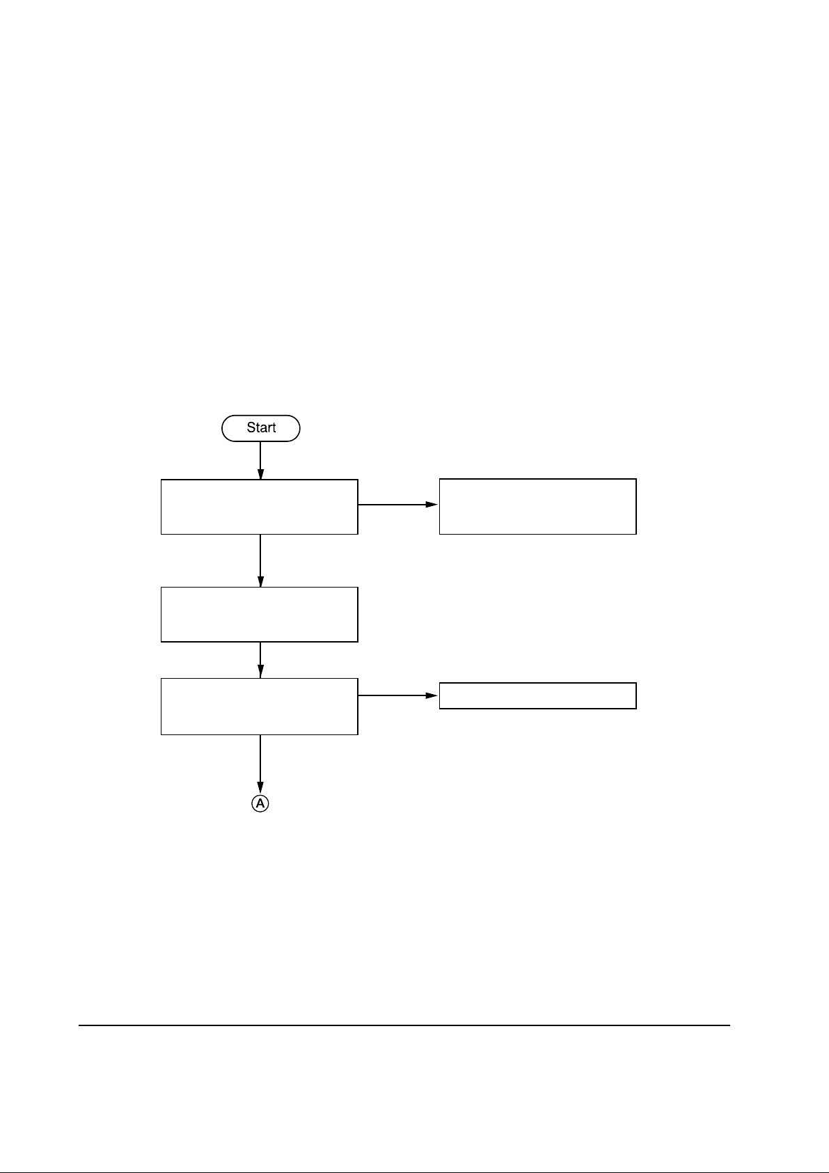
4-2-1 Analyzing basic hardware symptoms
Following this chart allows analyzing basic problems concerning the bulk stacker hardware. The
bulk stacker should be left installed to the printer in normal manner while following the flowchart.
Bulk stacker's connector (on top
of bulk stacker) mated properly
with the printer's?
Yes
Remove the right side cover of
bulk stacker. See Chapter 2;
section 2-2-3.
Is J7 (interface) of controller
board in bulk stacker connected
properly?
Yes
Continued on next page
No
No
Turn power off and try
remounting the printer on the
bulk stacker.
Connect properly.
ST-20
4-4
Page 5
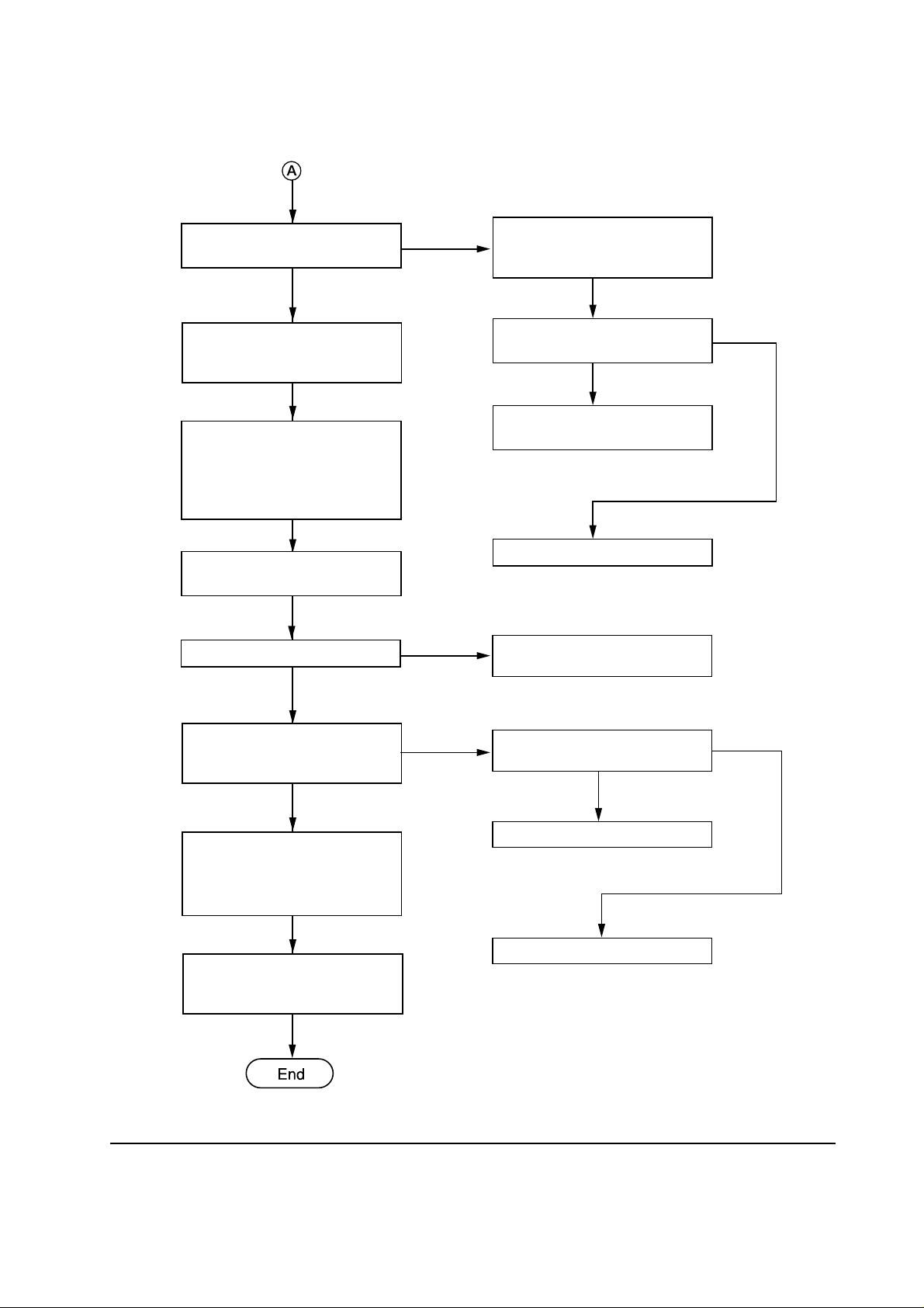
Continued
+5 V at pin 3 of J1 on controller
board?
No
Turn printer power off.
Disconnect stacker power cord
from the outlet.
Remove bulk stacker's top
cover. Remove jumper wires
TJ1 and TJ2 from controller
board, and insert them to (TJ1)
and (TJ2), respectively.
Connect bulk stacker power
cord from the outlet.
Feed motor rotates?
No
Yes
Yes
Remove the left side cover of
bulk stacker. See chapter 2;
section 2-2-2.
Yes
5 V DC at pin 3 (white) of
stacker connector?
Replace harness of bulk stacker
connector.
Replace printer engine board.
Replace power supply/motor
driver board in bulk stacker.
No
AC power across pins 1 and 3 of
J11 on bulk stacker's power
supply/motor driver board?
Yes
Check 24 V DC and 5 V DC
lines according to Checking the
24 V DC and 5 V DC lines on
next page.
Reset jumper wires (TJ1) and
(TJ2) back to TJ1 and TJ2 on
controller board, respectively.
No
AC power across pins 1 and 5 of
J12?
No
Replace AC harness.
Replace fuse F1.
4-5
Yes
ST-20
Page 6
4-2-2 Checking the 24 V DC and 5 V DC lines
The following two charts allow checking whether the DC power lines are correctly routed.
(1) Checking the 24 V DC line
24 V DC at the first pin of J1
on bulk stacker's controller
board?
No
24 V DC at the first pin of J1
and J10 on bulk stacker's power
supply/motor driver board?
No
24 V DC at pin 2 of J10 on bulk
stacker's power supply/motor
driver board?
Yes
Fuse F2 on bulk stacker's power
supply/motor driver board
blown?
Yes
Yes
Yes
No
Yes
Replace stacker's contoroller
board.
Replace harness to J1.
Unplug AC power cord.
Measure resistance across pins 1
and 2 of J10. Open and close the
bulk stacker rear cover. If
resistance won't vary, replace
the interlock switch and the
harness. If resistance vary,
replace bulk stacker's power
supply/motor driver board.
Replace power supply/motor
driver board in bulk stacker.
ST-20
Replace fuse F2. If not
corrected, replace power
transformer.
4-6
Page 7
(2) Checking the 5 V DC line
5 V DC at pin 3 of J1 on bulk
stacker's controller board?
No
5 V DC at pin 3 of J1 on bulk
stacker's power supply/motor
driver board?
No
Is fuse F3 on bulk stacker's
power supply/motor driver
board blown?
Yes
Replace fuse F3. If not
corrected, replace power
transformer.
Yes
Yes
No
Replace bulk stacker's controller
board.
Replace harness to J1.
Replace power supply/motor
driver board in bulk stacker.
4-7
ST-20
Page 8

4-2-3 Power supply/indicator panel problem
(1) Power supply problem
Power supply problem can mainly caused by the following causes:
Defect in the interface with the printer
Defect in the power supply/motor driver board
Troubleshooting to these items can be executed by following section 4-2-1, Analyzing basic hardware
symptoms, previously explained.
(2) Indicator panel problem
To isolate problems regarding the bulk stacker's indicator panel, use the chart below.
5 V DC at the first pin of J2 on
bulk stacker's controller board?
Yes
Harness properly connected?
Yes
Replace indicator panel.
Yes
Does indicator panel work?
Yes
No
No
No
Power supply problem. See the
previous page.
Reconnect the harness properly.
Replace bulk stacker's controller
board.
ST-20
4-8
Page 9

4-2-4 Interface problem
Interface problems are implied by the printer's front panel message Call Service person C1 or C4.
T o act with these messages, follow section 4-2-1 Analyzing basic hardware symptoms, then use the
chart below.
(1) Call service person C1 or C4
Follow flowchart Analyzing
basic hardware symptoms,
section 4-2-1.
Chart followed successfully?
Yes
Replace bulk stacker's
contoroller board.
Yes
No
Follow chart's instructions.
4-9
ST-20
Page 10

4-2-5 Mechanical problem
The bulk stacker's main mechanical component are listed as follows:
Feed motor
Duplexer selection solenoid (for routing paper to the bulk stacker or the duplexer)
The following flowchart can be used for isolating problems with all of the above motor and solenoid.
Before making investigation on each part, follow this chart first.
Set dipswitch (DS1) segments
of 1 and 2 of DS1 on bulk
stacker's controller board to ON
(left).
Remove bulk stacker's top
panel. Remove jumper wires
TJ1 and TJ2 from power
supply/motor driver board, and
insert them to (TJ1) and (TJ2),
respectively.
Plug bulk stacker's AC power
plug to the power outlet.
Test mode initated?
No
Yes
Controller board
Dipswitch
(DS1)
Power supply/motor driver board
RL1
TJ2 TJ1
(TJ2)
(TJ1)
Nomal position
ON
2
1
Test mode position
(Motor check)
ON
2
1
Test mode position
(Sensor check)
ON
2
1
See section 4-3-2
Check feed motor.
Replace bulk stacker's power
supply/motor driver board. (To
stop bulk stacker, unplug
power).
ST-20
J12
RL1
TJ2 TJ1
(TJ2)
(TJ1)
J12
When troubleshooting is finished,
reset jumper wire (TJ1) and (TJ2)
back to TJ1 and TJ2 on the power
supply/motor driver board,
respectively.
Figure 4-2-1 Test mode settings
4-10
Page 11

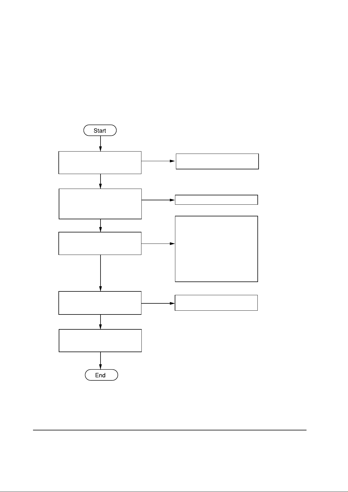
4-2-6 Feed motor problem
Start
12 V DC at pin 2 of J8 of power
supply/motor driver board?
No
Are pins 7 and 9 of J1 on power
supply/motor driver board at
low?
No
Are pins 7 and 9 of J1 on
controller board at low?
No
Replace bulk stacker's controller
board.
End
Yes
Yes
Yes
Check through 24 V DC line. If
OK, replace feed motor.
Replace power supply/motor
driver board.
Replace harness to J1.
4-11
ST-20
Page 12

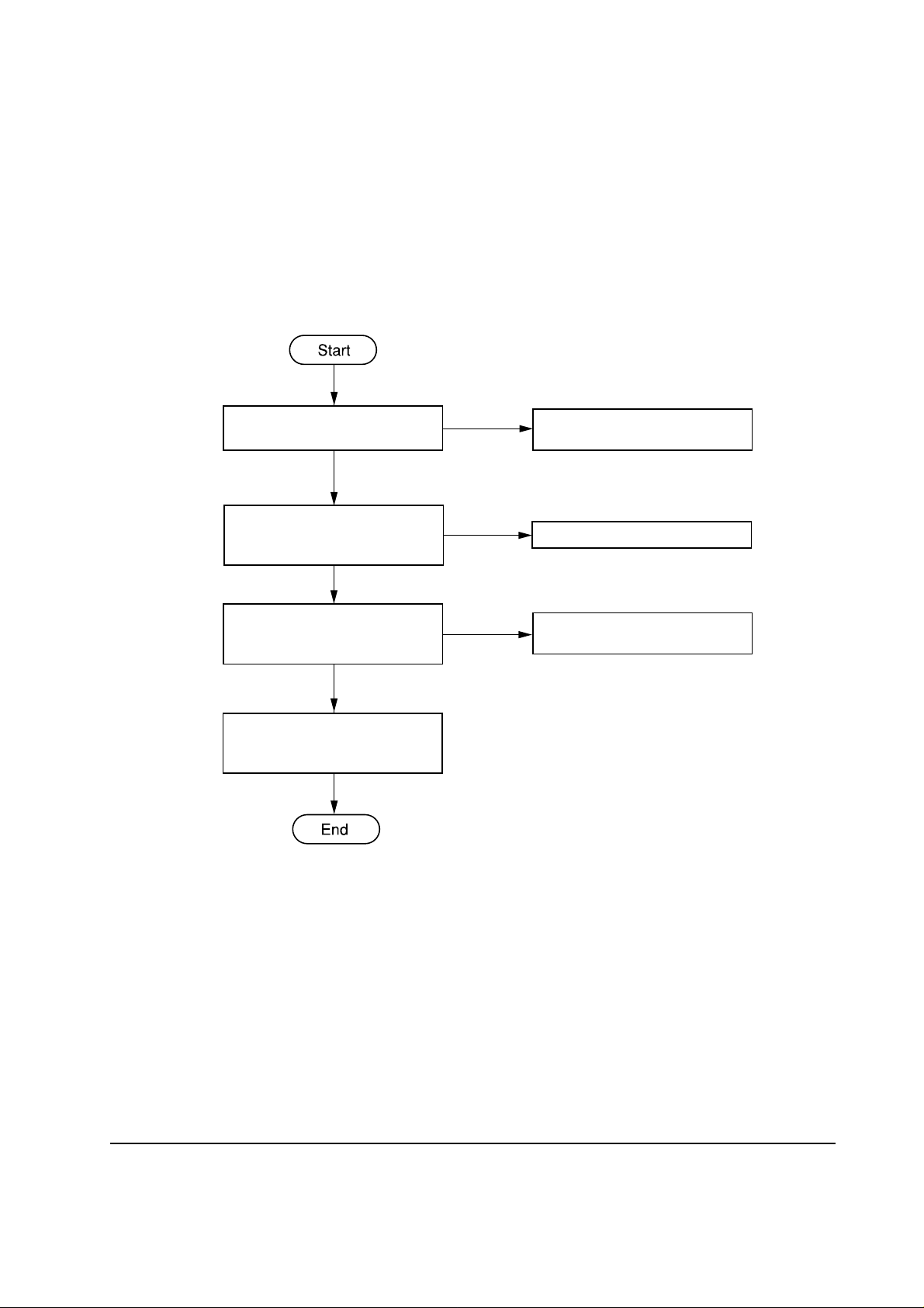
4-2-7 Duplexer selection solenoid problem
Duplexer selection solenoid is for switching paper to the bulk stacker or the duplexer.
24 V DC at pin 5 of J3 of
controller board?
Yes
Is pin 4 of J3 on controller
board toggling through on and
off?
Yes
Replace duplexer selection
solenoid.
No
No
Check through 24 V DC line.
Replace bulk stacker's controller
board.
ST-20
4-12
Page 13

4-2-8 Sensor problem
The bulk stacker uses sensors for detecting presence of paper (See section 4-2-9). The following
chart allows checking through these sensors when problem with sensors is encountered.
NOTE On power supply/motor driver board, move the jumper wires in sockets TJ1 and TJ2
to (TJ1) and (TJ2) [test mode position] , respectively.
(1) Inlet sensor
5 V DC at pin 10 of J5?
Yes
Manually activate the inlet
sensor actuator.
Does pin 11 of J5 turn to 0 V?
Yes
Replace bulk stacker's controller
board.
No
Check through 5 V DC line.
No
Replace inlet sensor.
4-13
ST-20
Page 14

(2) Paper tray exit sensor
5 V DC at pin 7 of J4?
Yes
Manually activate the paper tray
exit sensor actuator.
Yes
Does pin 8 of J4 turn to 0 V?
Yes
Replace bulk stacker's controller
board.
No
No
Check along 5 V DC line.
Replace paper tray exit sensor.
ST-20
4-14
Page 15

(3) Paper tray full sensor
5 V DC at first pin of J4?
Yes
Manually activate the paper tray
full sensor.
Yes
Does pin 2 of J4 turn to 0 V?
Yes
Replace bulk stacker's controller
board.
No
No
Check along 5 V DC line.
Replace paper tray full sensor.
4-15
ST-20
Page 16

4-2-9 Location of sensors
Figure 4-2-2 below shows the name and location of all sensors used in the option units.
Paper empty sensor (EF-1)
Feed sensor
(HS-20/HS-21)
Paper empty sensor
(PF-20/PF-21)
Feed sensor
(DU-20/DU-21)
Paper empty sensor
(DU-20/DU-21)
Inlet sensor
Paper tray exit sensor
Adjustment guide
home positioning
sensor (DU-20/DU-21)
Feed sensor
(DU-20/DU-21)
*For resupplied paper
Paper tray full sensor
Bulk stacker ST-20
ST-20
Figure 4-2-2 Location of sensors
4-16
Page 17

4-3 Paper jam problem
This section explains how to cope with paper jam problem that occurs in the bulk stacker. Paper
jam in the bulk stacker is indicated by flashing READY indicator on the bulk stacker front side. If
the bulk stacker and the printer seem not to recover from paper jam after jammed paper is removed,
begin troubleshooting by following the Analyzing paper jam problem (basic) flowchart on next
page.
4-17
ST-20
Page 18

4-3-1 Analyzing paper jam problem (basic)
bulk stacker
installed as per
specifications?
Yes
Turn printer power on.
Is POWER lit?
Yes
Stacker
selectable in STACK
SELECT key?
Yes
Is READY lit?
No
Refer to stacker's
No
specifications.
Chapter 1,
section 1-5.
Check
connectors and
power supply.
No
Check electrical
troubleshooting.
No
Check electrical
troubleshooting.
ST-20
Yes
Print a status page.
Paper jam?
No
Yes
Follow analyzing
paper jam
problems flow
chart. section 43-2.
4-18
Page 19

4-3-2 Analyzing paper jam problems
Follow the flowchart below when instructed to do so while following the Analyzing paper jam
problem (basic) flowchart (section 4-3-1). This flowchart will in turn lead you to the specific
remedy as tabled in Table 4-3-1.
Duplexer
installed (above
stacker) ?
No
Paper path
adaptor mounted
on duplexer?
No
Install PA-1 paper path
adaptor.
Paper jammed
at entrance of
bulk stacker?
Yes
Yes
Yes
Paper
jammed in
duplexer?
No
Is the
correct adaptor
model used?
Yes
Go to Table 4-31, item 2.
Yes
No
Go to Table 4-31, item 1.
Change adaptor
to the correct
one.
No
ST-20
4-19
Page 20

The table below summarizes various symptoms and remedies for paper jam problems. Use this
table according to the directions obtained by following the Analyzing paper jam problems flowchart.
Table 4-1 Remedies for paper jam problems
Item CauseSymptom
Paper missed
1
to enter bulk
stacker but
entered
duplexer and
jammed.
Paper trapped
2
at the entrance
of bulk stacker.
Defective duplexer
selection solenoid.
Defective duplexer
switching flap.
Defective duplexer
selection solenoid.
Paper path adaptor is PA1 is not mounted on bulk
stacker (if paper feeder is
mounted above bulk
stacker), or paper path
Suggested remedy
Check solenoid assembly for proper
operation. Replace solenoid assembly if
necessary.
Check the flap switching lever at duplexer
bottom for proper operation. Replace the flap
switching lever if necessary.
After executing remedy , confirm bulk stacker
and duplexer work properly by running bulk
stacker in self test mode. See chapter 4,
section 4-2-5.
Obtain and install a correct PA-1.
adaptor PA-1D is
mounted on bulk stacker.
Bulk stacker's entrance
roller (or PA1-D roller)
did not revolve due to
excessive disc clutch
effect.
Loose driving belt
tension or belt not
hooked properly.
Defective feed motor.
Replace disc clutch assembly.
Hook belt properly and adjust the tension
properly.
Confirm motor and driver mechanism work
properly by running bulk stacker in self test
mode. To set test mode of bulk stacker, see
chapter 4, section 4-2-5. Replace feed motor
if necessary.
ST-20
4-20
Page 21

Item CauseSymptom Suggested remedy
Paper jammed
3
after clearing
sensor.
Defective sensor(s). See
Figure 4-2-2 for
location of sensors.
Clean sensor. Check sensor actuator for
smooth elevation.
Operate bulk stacker in sensor test mode:
Remove jumper wires from TJ1/TJ2 and insert
them into (TJ1/TJ2) on power supply/motor
driver board, and set segment 1 of dipswtch
(DS1) to ON and segment 2 of DS1 to OFF,
See figure 4-2-1. Plug bulk stacker to power.
Feed A5 paper from the bulk stacker's inlet.
Check if READY on the bulk stacker flashes
two times (once at the inlet sensor and at the
paper tray exit sensor. Replace sensor(s) if
necessary.
4-21
ST-20
 Loading...