

Page 1

Chapter 3
Paper specifications
Page 2

Chapter 3 Contents
3-1 Introduction ...................................................................................................................................... 3-3
3-2 Power supply/motor driver board .................................................................................................. 3-4
3-2-1 Power supply circuit........................................................................................................................ 3-4
3-2-2 Motor driver circuit .......................................................................................................................... 3-5
3-3 Controller board............................................................................................................................... 3-6
3-3-1 Solenoid driver................................................................................................................................ 3-7
3- 4 Printer interface .............................................................................................................................. 3-8
3-4-1 Connector configuration.................................................................................................................. 3-8
3-4-2 Controller board CPU I/O interface................................................................................................. 3-9
3-5 Sensors........................................................................................................................................... 3-11
3-6 Error message................................................................................................................................ 3-12
3-7 Printing timing charts.................................................................................................................... 3-13
Page 3

3-1 Introduction
This chapter explains the operation of the electrical circuits in the bulk stacker. Procedures for
hardware troubleshooting are also included in this chapter. Schematic diagrams are provided in
Appendix. The schematic diagram should be referred to along with the explanation in the following
pages.
The electrical system of the bulk stacker can be functionally divided in the following two parts:
Power supply/motor driver
Controller
These two part are mounted on separate circuit-boards. Details on each part follow are explained
on the following pages.
3-3
ST-20
Page 4
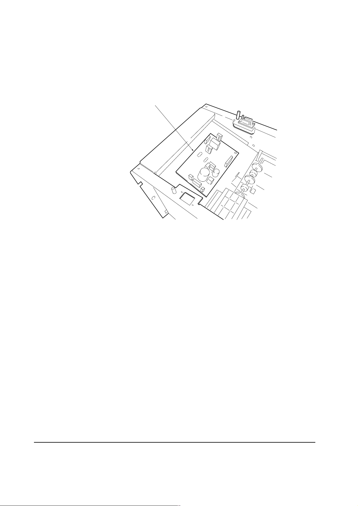
3-2 Power supply/motor driver board
See figure 3-2-1 below. The motor driver/power supply board is located on the top of the bulk
stacker, inside the top plate.
Power supply/motor driver board
Figure 3-2-1 Location of power supply/motor driver board
3-2-1 Power supply circuit
See appendix power supply/motor driver board circuit diagram.
The bulk stacker has no power switch provided as the printer's power switch simultaneously activates
the bulk stacker's power supply. When printer power turns on, the 5 V DC reaches at pin #3 of the
interface connector. It activates and closes relay RL1 on the motor driver/power supply board
which in turn connects the primary power (120 or 220 V AC) to transformer T1. The power supply
section produces both the 5 V and 24 V DC and feeds them accordingly to the respective circuits.
Regulator IC1 is provided for the 5 V DC power supply.
ST-20
3-4
Page 5

3-2-2 Motor driver circuit
See appendix power supply/motor driver circuit board diagram.
The motor driver receives commands for driving the feed motor from the controller board through
connector J1.
The feed motor is located on the top of the bulk stacker, inside the top panel. The feed motor drives
the feed roller for feeding paper arriving from the printer towards the paper tray. Power voltage for
this motor is regulated by means of resistors R11 and R14 on the power supply/motor driver board
so as to obtain a constant 16 V DC source. The feed motor turns on when the level of pin #9 of J1
(FEEDON*) becomes low.
3-5
ST-20
Page 6

3-3 Controller board
The controller board is located on the right inside of the bulk stacker as shown in figure 3-3-1
below.
Controller board
Figure 3-3-1 Location of the controller board
A 4-bit CPU (µPD75004) is used in the controller board to manage controlling the following devices,
while keeping contact with the printer using the serial communication method.
Solenoid driver
Printer interface
Sensor controller
Details on each of these devices follow.
ST-20
3-6
Page 7

3-3-1 Solenoid driver
The bulk stacker has one solenoid (Duplexer selection solenoid). Solenoid is located as shown in
Figure 3-3-2 below and changes the paper path according to the simultaneous activation of the
duplexer (DU-20/DU-21).
See figure 3-3-3, If the bulk stacker is used together with the duplexer for duplex printing, the CPU
IC1 turns the DPSON* signal low , which in turn ener gizes duplexer selection solenoid to allow the
paper to be fed into the duplexer.
Duplexer selection solenoid
Figure 3-3-2 Duplexer selection solenoid
24 V DC
CPU
IC1
37
14
Driver
IC3
15
DPSON*
Figure 3-3-3 Solenoid control signal
3-7
Duplexer
selection
solenoid
ST-20
Page 8

3- 4 Printer interface
This section provides information regarding the bulk stacker's interface to the printer.
3-4-1 Connector configuration
The bulk stacker and the printer exchange signals between each other through connector J7 which
is mounted on top the bulk stacker . The names and the functions of the signals handled by the bulk
stacker are as follows.
5 4 3 2 1
6 7 8 9 10
Bulk stacker's left side
Printer positioning pin
Figure 3-4-1 Bulk stacker connector
Table 3-4-1 Bulk stacker connector pin assignment
Pin No. Input/Output Signal Description
1 Input DSENS Duplexer’s feed path sensor (open collector) output
(24 V DC if duplexer is installed above the bulk
stacker)
2 Input SCKD Serial clock
3 Input +5 V 5 V DC power
4 Output READY Hand shake signal
5 Input SEL0 Select bit 0
6 Input SEL1 Select bit 1
7 Input SEL2 Select bit 2
8 Output SID Bulk stacker output data
9 Input SOD Bulk stacker input data
10 - GND Ground
ST-20
3-8
Page 9

Signals SEL0, SEL1, and SEL2 are used by the printer to select and deselect the bulk stacker. The
bulk stacker is selected as the paper destination when SEL0 is “1”, SEL1 is “0”, and SEL2 is “1”.
All levels are of C-MOS level. Pulled-up for input and open-circuited for output. The clocksynchronous serial interface configuration is used with the maximum synchronization clock of 200
kHz.
3-4-2 Controller board CPU I/O interface
Table 3-1 below shows signals used by the controller board CPU (µPD75004) for its I/O interface.
Table 3-4-2 Controller board CPU I/O signals
Pin Input/Output Signal Description Logic (Meaning)
12
-
SOD(SI)
Printer's communication
14
18, 19
17
25
24
22, 23
31
32
33
27-29
10, 11
13
9
40, 41
39
-
Input
Input
Input
-
Input
-
-
-
-
Output
Output
SCKD*
RCOPN*
DSENS
SOIN*
-
NSBF*
SEL0-SEL2
DIPSW1-DIPSW2
SID (SO)
READY*
FEEDON*
Communication clock
Not used
Rear cover status
Paper feeding in duplexer
Paper detection in bulk stacker's
paper inlet
Not used
Not used
Paper full in paper tray
Not used
Bulk stacker activation bits
Bulk stacker mode selection bits;
“1” for both bits (at power on)
Status to printer (communication)
Ready to send status
Not used
Feed motor status
-
Cover open
No paper
Paper detected
-
-
Paper full
-
-
-
-
-
Ready
-
On
On
38
37
34-36
6, 7
Output
Output
-
-
RDYLED*
DPSON*
-
-
READY indicator status
Path selection/duplexer
Not used
Not used
3-9
To duplexer
-
-
-
ST-20
Page 10

The following table shows port assignment for the controller board CPU (µPD75004).
Table 3-4-3 Controller board CPU pin assignment
Port bit3 bit2 bit1 bit0
Port0
Port1
Port2
Port3
Port4
Port5
Port6
Port7
Port8
SI
-
-
RDYLED*
-
-
-
-
SO
RCOPN*
NSIN*
VLOW*
FEEDON*
-
SEL2
-
SCK
SOIN*
-
-
NSBF*
SEL1
DIPSW2
-
DSENS*
READY*
DPSON*
SEL0
DIPSW1
ST-20
3-10
Page 11

3-5 Sensors
The bulk stacker has sensors provided for controlling paper transportation and detection of paper
jam. The following sensors are used:
Table 3-5-1 Controller board CPU input sensors signals
Sensor Signal Function Type of sensor Logic
Inlet sensor
Paper tray
exit sensor
Paper tray
full sensor
SOIN*
NSIN*
NSBF*
Mounted at the paper inlet of
the bulk stacker. Detects the
paper fed and occurrence of
paper jam; provides various
timings for bulk stacker
control.
Located at the paper tray exit.
Detects timing of paper exit
and occurrence of paper jam.
Detects if the paper tray
becomes full (approximately
1500 sheets).
Photo
interrupter
Photo
interrupter
Photo
interrupter
Pin #24 of CPU
IC1 turns to low
while paper is
sensed.
Pin #23 of CPU
IC1 turns to low if
paper exists.
Pin #32 of CPU
IC1 becomes low
when the paper
tray is full.
3-11
ST-20
Page 12

3-6 Error message
The printer looks after itself and shows various error codes starting with the Call Service person
message if a defect is found during operation. The error messages pertaining to use of the bulk
stacker together with the printer are as follows.
Table 3-6-1 Error codes regarding bulk stacker
Error code Meaning Suggested remedy
C4
C5
C6
For other error codes, refer to printer's Service Manual.
Defect in communication between the
bulk stacker and the printer engine.
Error during self-diagnostics of bulk
stacker.
Defect at power-up in communication
between the bulk stacker and the
printer engine.
Replace the printer’s engine
board. Replace the bulk
stacker’s controller board.
Replace the connector of bulk
stacker.
Replace the bulk stacker’s
feed motor. Replace the bulk
stacker’s power supply/motor
driver board.
Replace the printer’s engine
board. Replace the bulk
stacker’s controller board.
Replace the connector of bulk
stacker.
ST-20
3-12
Page 13

3-7 Printing timing charts
FS-3700/ST-20/A4
3-13
FS-3700 Motor
(MMOT)
FS-3700 Cassette feed
(FDCL1)
FS-3700 Registration clutch
(REGCL)
FS-3700 Registration sensor
(JAMR)
FS-3700 Fuser sensor
(JAM0)
HS-20 Motor
(MON, VLOW)
HS-20 Sensor
(HSPAP)
ST-20 Feed motor
(FEED)
ST-20 Inlet sensor
(SOIN)
ST-20 Paper tray exit sensor
(NSIN)
0 (s)
1055 (ms)
1055
24
2454
2012
2620
2243
High speed
2621
4311
5163
4117
Low speed
4697
5382
5495
6
5706
5872
5918
6754
6798
6899
810
8413
7369
7948
7500
9170
7807
7748
8532
10011
10055
9170
9194
10154
12 14
11842
11842
10760
12445
11070
11010
11800
ST-20
Page 14

ST-20
FS-3700/DU-20/ST-20/A4 (Continued to next page)
3-14
FS-3700 Motor (MMOT)
FS-3700 Cassette feed
(FDCL1)
FS-3700 Registration clutch
(REGCL)
FS-3700 Registration sensor
(JAMR)
FS-3700 Fuser sensor (JAMO)
HS-20 Motor (MON, VLOW)
HS-20 Sensor (HSPAP)
DU-20 Motor
(FEED0, FEED1, VLOW)
DU-20 Clutch (CLON)
DU-20 Stepping motor
(PA, PB, PA_, PB_)
DU-20 Entrance sensor (PISNS)
DU-20 Home sensor (PHSNS)
DU-20 Exit sensor (POSNS)
DU-20 Guide home sensor
(GHOME)
ST-20 Feed motor (FEEDON)
ST-20 DU-1/ST-20 (DPSON)
ST-20 Inlet sensor (SOIN)
ST-20 Paper tray exit sensor
(NSIN)
0 (s)
4
4500
5456
5702
4500
High speed
6068
6
6914
6082
5982
FWD.
High speed
6218
CCW
6178
6218
810
9022
9978
8626
7576
8160
Low speed
9378 17020
10432
10216
10218
10266
High speed
10488
12 14 16 18 20 22 24 26
11130
11716
12412
13437
13587
CW
13724
REV.
Low speed
15166
15218
15166
15360
16492
16268
15800
FWD.
High speed
16936
16936
16100
16498
16748
17104
16812
17850
17706
17106
16788
CCW
16788
18800
18612
18172
FWD.,REV.
18180
18180
1826416630
19660
19182
18908
19488
19532
19524
20206
19870
19992
20408
21211
20186
20374
21248
21296
21361
CW
21754
21870
22042
21816
21816
23288
22008
23398
22608
22920
22450
22750
22706
22668
23140
23460
23672
23586
23586
23438
CCW
23146
23438
23408
23750
24500
24826
23758
23758
24050
25450
25264
25834
24832
24832
24936
Page 15

FS-3700 Motor (MMOT)
FS-3700 Cassette feed
(FDCL1)
FS-3700 Registration clutch
(REGCL)
FS-3700 Registration sensor
(JAMR)
FS-3700 Fuser sensor (JAMO)
22 (s)
22920
23140
23460
24
23758
24508
25450
25264
26
26522
26312
26854
27024
26642
27900
28 30
29788
Repeat
29566
28522
30398
30108
31156
32 44 36 38
36332
36624
36330
31904
32954
34544
28310
39178
40
42 44 46 48
FS-3700/DU-20/ST-20/A4 (Continued)
43941
40768
3-15
ST-20
HS-20 Motor (MON, VLOW)
HS-20 Sensor (HSPAP)
DU-20 Motor
(FEED0, FEED1, VLOW)
DU-20 Clutch (CLON)
DU-20 Stepping motor
(PA, PB, PA_, PB_)
DU-20 Entrance sensor (PISNS)
DU-20 Home sensor (PHSNS)
DU-20 Exit sensor (POSNS)
DU-20 Guide home sensor
(GHOME)
ST-20 Feed motor (FEEDON)
ST-20 DU-1/ST-20 (DPSON)
ST-20 Inlet sensor (SOIN)
ST-20 Paper tray exit sensor
(NSIN)
22450
22042
22008
23146
22608
23586
23586
23288
23398
22706
22668
23672
23758
23758
23438
CCW
22750
23438
23408
24826
24050
25834
25562
24832
24832
24936
26164
26836
26206
26198 29386
30320
30230
30230
30082
CCW
30082
30096
30398
30398
30740
31466
31476
31476
31612
32476
32206
32846
33482
32888
32880
27944
27060
27861
CW CW
28462
28011
28658
28436
29098
28706
28462
29932
29400
29796
30042
39350
29288
34590
34688
34688
34507
34657
34870
35116
3535633700
35622
35978
36454
36454
36016
36042
36624
36624
37430
36788
37700
37700
37454
38702
38066
39926
40812
41580
41336
42264
42200
42596
47576
43560
43684
43018
 Loading...