

Page 1

ST-11
SERVICE
MANUAL
Published in Jun.’00
843BF110
Page 2

CONTENTS
1-1 Specifications
1-1-1 Specifications ....................................................................................................................................... 1-1-1
1-1-2 Parts names ......................................................................................................................................... 1-1-2
1-1-3 Machine cross section.......................................................................................................................... 1-1-3
1-1-4 Drive system ........................................................................................................................................ 1-1-4
1-2 Installation
1-2-1 Unpacking ............................................................................................................................................ 1-2-1
(1) Unpacking....................................................................................................................................... 1-2-1
(2) Removing tapes and pads .............................................................................................................. 1-2-2
1-3 Maintenance Mode
1-3-1 Maintenance mode............................................................................................................................... 1-3-1
1-4 Troubleshooting
1-4-1 Paper misfeed detection ...................................................................................................................... 1-4-1
(1) Paper misfeed detection ................................................................................................................. 1-4-1
(2) Paper misfeed detection condition ................................................................................................. 1-4-1
(3) Paper misfeed ................................................................................................................................ 1-4-1
1-4-2 Self-diagnosis....................................................................................................................................... 1-4-2
(1) Self-diagnostic function .................................................................................................................. 1-4-2
(2) Self-diagnostic code ....................................................................................................................... 1-4-2
1-4-3 Electrical problem................................................................................................................................. 1-4-2
3BF
1-5 Assembly and Disassembly
1-5-1 Precautions for assembly and disassembly ......................................................................................... 1-5-1
(1) Precautions..................................................................................................................................... 1-5-1
1-5-2 Procedure for assembly and disassembly ........................................................................................... 1-5-1
(1) Adjusting the center line ................................................................................................................. 1-5-1
2-1 Mechanical construction
2-1-1 Mechanical construction....................................................................................................................... 2-1-1
2-2 Electrical Parts Layout
2-2-1 Electrical parts layout ........................................................................................................................... 2-2-1
(1) PCBs, motors and clutches ............................................................................................................ 2-2-1
(2) Switches ......................................................................................................................................... 2-2-2
2-3 Operation of the PCB
2-3-1 Side deck main PCB ............................................................................................................................ 2-3-1
2-4 Appendixes
Timing chart.................................................................................................................................................... 2-4-1
Wring diagram ................................................................................................................................................ 2-4-2
1-1-1
Page 3

1-1-1 Specifications
3BF
Type .............................................. Deck type
Paper ............................................ Plain paper (64 - 80 g/m
Paper size ..................................... A4/11" × 8
1
/2"
Capacity ........................................ 4000 sheets (80 g/m
2
)
2
)
Power source ................................ Electrically connected to the copier (5 V DC, 24 V DC)
Dimensions ...................................371 (W) × 589 (D) × 685 (H)* mm
5
14
/8" (W) × 233/16" (D) × 2615/16"* (H)
*: The height includes that of casters.
Weight...........................................Approximately 36 kg/79.2 lbs
1-1
1-1-1
Page 4
1-1
3BF
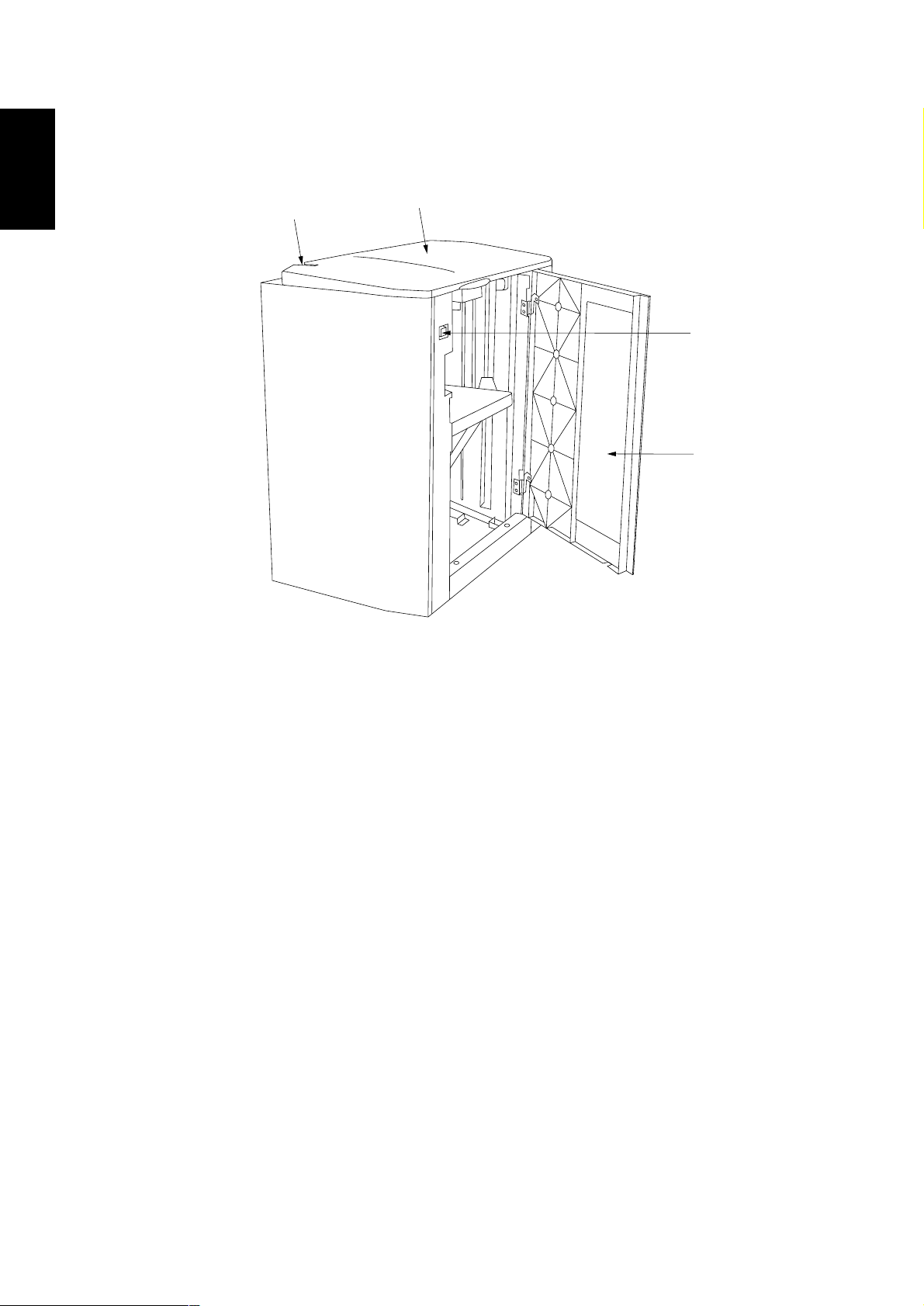
1-1-2 Parts names
4
1
3
2
Figure 1-1-1 Parts names
1 Upper cover
2 Right cover
3 Right down switch
4 Side deck release button
1-1-2
Page 5
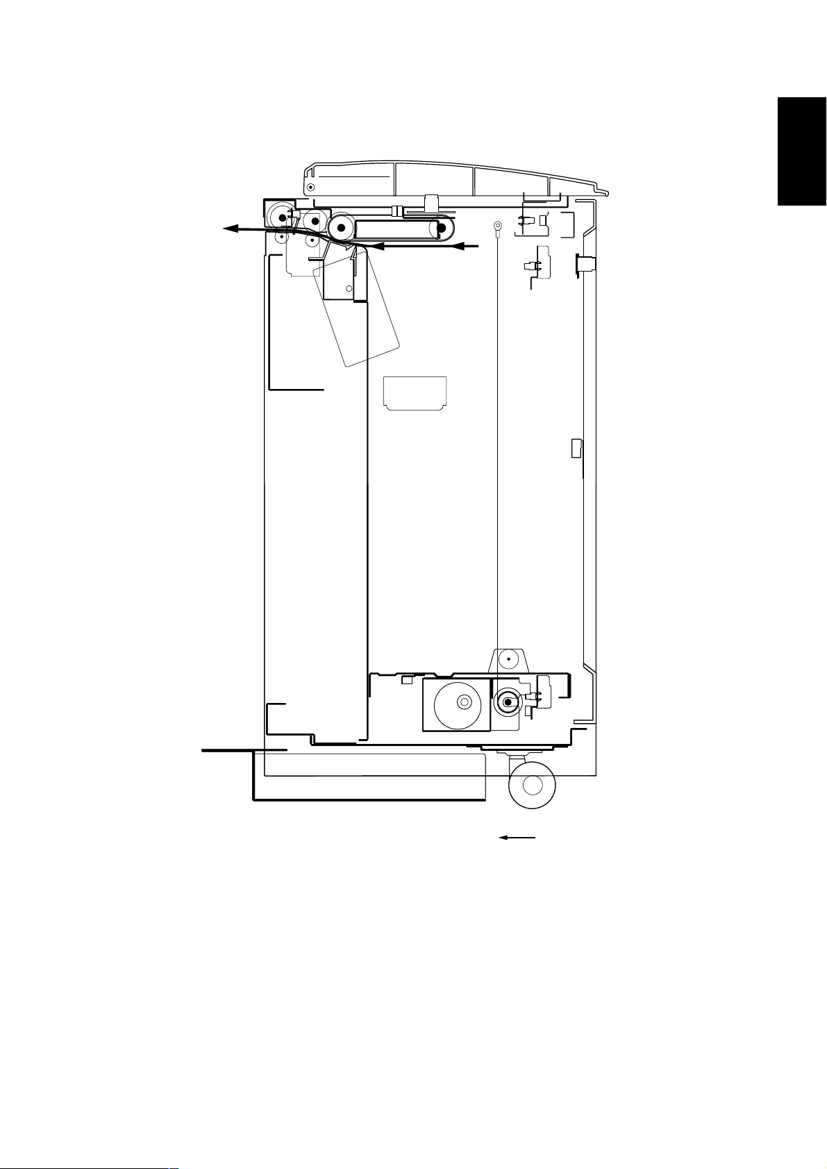
1-1-3 Machine cross section
3BF
1-1
Figure 1-1-2 Cross section
Paper path
1-1-3
Page 6
3BF
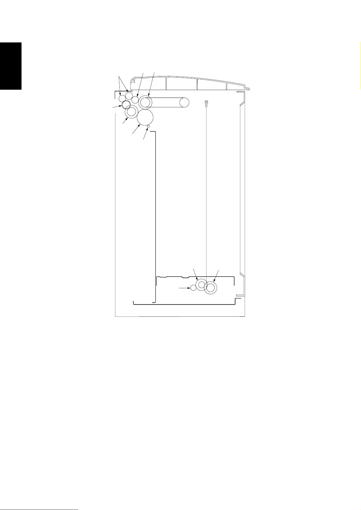
1-1-4 Drive system
1-1
4
5
3
2
6
1
7
9
8
Figure 1-2-3 Drive system
1 Paper feed motor gear
2 Feed gear 55/45
3 Duplex drive gear 24/36
4 Idle gear 20/24
5 Developing gear 20
6 Eject gear 20
7 Paper feed cluch gear
8 Lift gear 16
9 gear 31/17
0 Oil roller gear
0
1-1-4
Page 7
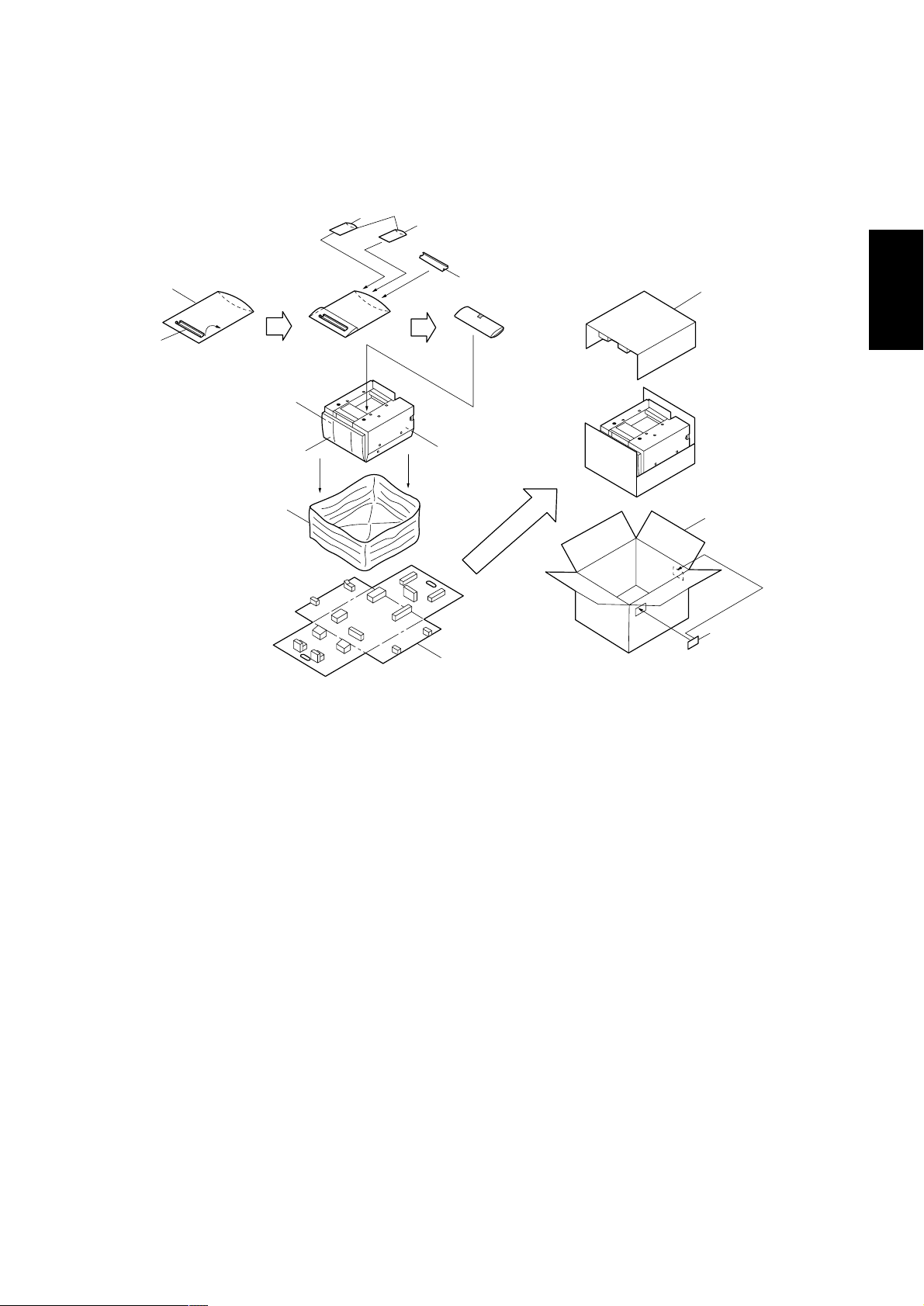
1-2-1 Unpacking
^
(1) Unpacking
3BF
2
&
!@
$
1
4
5678
3
%
0
#
1-2
*
9
Figure 1-2-1 Unpacking
1 Side deck
2 Upper merge guide
3 Lower merge guide
4 Interlock switch backstop
5 Cross-head chromate binding screw, CVM4 x 06
6 Flat-cross-head chromate screw, FHM4 x 12
7 Cross-head TP tap-tight P chromate screw, M4 x 6
8 Cross-head TP tap-tight P chromate screw, M4 x 8
9 Bottom pad
0 Top pad
! Lift spacer
@ Guide spacer
# Outer case
$ Machine cover
% Cover spacer
^ Plastic bag (70 x 110 mm)
& Air padded bag (400 x 500 mm)
* Bar code labels
1-2-1
Page 8
3BF
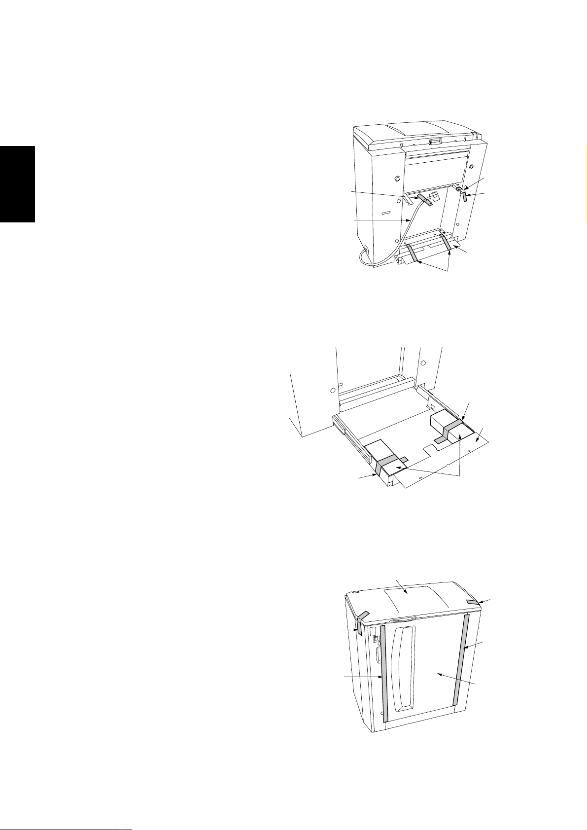
(2) Removing tapes and pads
Remove the tapes and pads as follows before machine installation.
1. Remove the tape securing the hook.
2. Remove the tape securing the signal cable.
3. Remove the two tapes securing the base
retainer.
1-2
4. Draw the base retainer out and remove the
tape securing each of the two base spacers
and then the spacers.
Tape
Signal cable
Hook
Tape
Base retainer
Tapes
Figure 1-2-2
Tape
Base retainer
5. Remove the two tapes securing each of the
upper and right covers.
Tape
Tape
Tape
Base spacers
Figure 1-2-3
Upper cover
Tape
Tape
Right cover
Figure 1-2-4
1-2-2
Page 9

6. Open the right cover and remove the tape
securing the cover spacer and then the
spacer.
7. Open the upper cover and remove the guide
spacer.
8. Remove the tape securing each of the two lift
spacers and then the spacers.
3BF
Cover spacer
Tape
1-2
Right cover
Figure 1-2-5
Guide spacer
Tape
Lift spacers
Figure 1-2-6
Tape
Upper cover
1-2-3
Page 10

1-3-1 Maintenance mode
3BF
Maintenance
item No.
U208 Setting the deck lift operation
Description
Sets the operation of the side deck lift motor for when paper in the side deck is exhausted.
Purpose
To be set according to the paper loading method.
Method
Press the start key. The screen for selecting an item is displayed.
Setting the paper loading method
1 Select the method to load paper at the screen for selecting an item.
Display
Side Feed
Upper Feed
Initial setting: Side Feed
2 Press the start key. The setting is set. The screen for selecting a maintenance item No. is displayed.
Completion
To exit this maintenance item without changing the current setting, press the stop/clear key. The screen for
selecting a maintenance item No. is displayed.
U247 Checking the operation of the side deck motors and clutches
Description
Turns on motors and clutches of the side deck.
Purpose
To check the operation of motors and clutches of the side desk devices.
Start
1 Press the start key. The screen for selecting an item is displayed.
Method
1 Press the item to be operated. The selected item is displayed in reverse and operation starts.
Display
SDECK MOT
SDECK FAN
SDECK LIFT
SDECK CVCL
LDECK FDCL
To stop the side deck lift motor, press the stop/clear key.
If this maintenance item is executed with the upper cover of the side deck open, detection of the upper
limit is not possible and thus the side deck lift motor overruns.
Completion
Press the stop/clear key at the screen for selecting an item. The screen for selecting a maintenance item
No. is displayed.
Description
Load paper through the right cover.
Load paper through the upper cover.
Motors and solenoids
Side deck drive motor (SDDM)
Separation fan motor (SFM) and Suction fan motor (IFM)
Side deck lift motor (SDLM)
Side deck paper conveying clutch (SDCCL)
Side deck paper feed clutch (SDPFCL)
Description
1-3
U337 Setting the paper size for the side deck
Description
Sets the paper size for the side deck.
This maintenance item is applied to only Japanese specification machines, so no setting is necessary.
1-3-1
Page 11

3BF
1-4-1 Paper misfeed detection
(1) Paper misfeed detection
When a paper jam occurs, the machine stops operating immediately. The copier operation section shows a jam message
and the jam location.
To remove the jammed paper, detach the side deck from the copier.
(2) Paper misfeed detection condition
• No paper feed from side deck (jam code 15)
Paper feed switch 1 (PFSW1) of the copier does not turn on within 848 ms of the side deck paper feed clutch (SDPFCL)
turning on; the clutch is then successively held off for 1 s and turned back on twice, but the switch again fails to turn on
within 848 ms.
SDPFCL Off
PFSW1
(Copier)
848 ms 848 ms
1 s 1 s
848 ms
Timing chart 1-4-1
(3) Paper misfeed
Problem Causes/check procedures Corrective measures
A paper jam in the
side deck is
indicated during
copying.
Check if the side deck
paper feed clutch
malfunctions.
Electrical problem with the
Check and repair if necessary.
Check (see page 1-4-2).
side deck paper feed
clutch.
On
Off
On
1-4
1-4-1
Page 12

1-4
3BF
1-4-2 Self-diagnosis
(1)Self-diagnostic function
When a problem is detected in the side deck, copying is disabled and the copier operation section displays a code
consisting of “C” followed by a number, indicating the nature of the problem.
After removing the problem, the self-diagnostic function can be reset by reattaching the side deck.
(2)Self diagnostic code
Code Contents
C032
Side deck communication problem
• An error code from the side deck is
detected eight times in succession.
No communication: there is no reply
after 3 retries.
Abnormal communication: a
communication error (parity or
checksum error) is detected five times
in succession.
Causes Check procedures/corrective measures
Poor contact in
the connector terminals.
Defective copier
engine PCB.
Defective copier
main PCB.
Defective side
deck main PCB.
Remarks
Check the connection of connector CN9 on
the copier main PCB and the connector
CN3 on the side deck main PCB, and the
continuity across the connector terminals.
Repair or replace if necessary.
Replace the copier engine PCB and check
for correct operation.
Replace the copier main PCB and check
for correct operation.
Replace the side deck main PCB and
check for correct operation.
1-4-3 Electrical problem
Problem Causes Check procedures/corrective measures
The side deck paper
feed clutch does not
operate.
Broken side deck paper
feed clutch coil.
Poor contact of the side
deck paper feed clutch
connector terminals.
Defective side deck main
PCB.
Check for continuity across the coil. If none, replace the side
deck paper feed clutch.
Reinsert the connector. Also check for continuity within the connector cable. If none, remedy or replace the cable.
Check if CN5-A10 on the side deck main PCB goes low. If not,
replace the side deck main PCB.
1-4-2
Page 13

3BF
1-5-1 Precautions for assembly and disassembly
(1) Precautions
• Be sure to turn the main switch off and disconnect the finisher power plug before starting disassembly.
• When handling PCBs, do not touch connectors with bare hands or damage the boards.
• Do not touch any PCB containing ICs with bare hands or any object prone to static charge.
1-5-2 Procedure for assembly and disassembly
(1) Adjusting the center line
Make the following adjustment if there is a regular error between the center lines of the original and the copy image when
paper is fed from the side deck.
Note: Before performing this adjustment, be sure to perform the center line adjustment of the copier.
Procedure
1. Run maintenance item U034 and make a test
copy.
2. Measure the discrepancy L (mm) between the
center lines of the paper and test copy.
3. Open the lower vertical conveying cover of the
copier. Loosen the two screws securing the deck
retainer and move the V-shaped groove on the
deck retainer by the measured amount L and
retighten the screws.
• If the center line is shifted to the machine front,
move the V-shaped groove of the deck retainer
toward the machine front (copy example 1).
• If the center line is shifted to the machine rear,
move the V-shaped groove of the deck retainer
toward the machine rear (copy example 2).
Screw
Screw
1-5
Figure 1-5-1
L
Copy example 1 Copy example 1
Figure 1-5-2
L
1-5-1
Page 14

3BF
2-1-1 Mechanical construction
The side deck consists of the paper lifting mechanism, which winds up paper with the wire of the side deck lift motor
(SDLM), and the paper feed and conveying mechanism, which conveys paper with the drive of the paper conveying belt,
feed roller and left feed roller.
The side deck lift motor (SDLM) raises the lift by winding up the wire engaged with the pulley. The lift is stopped at the upper
and lower limit by the control of the upper limit detection switch (ULPSW) and lower limit detection switch (LLPSW).
Paper is fed by controlling currents of air. The top sheet of the paper loaded on the lift is floated by the separation fan motor
(SFM) and then induced onto the paper conveying belt by the suction fan motor (IFM). The sheet thus attracted to the paper
conveying belt is then conveyed to the feed roller and left feed roller by the drive of the side deck drive motor (SDDM).
1
2
#
*
%
%
!
¤
‹
9
$
(
^
0
@
3
5
›
fi
^
)
&
fl
4
⁄
6
‡
·
°
‚Œ
8
7
„
2-1
1 Upper paper conveying guide
2 Lower paper conveying guide
3 Paper guide
4 Paper conveying belt retainer
5 Left side deck guide
6 Upper limit switch mount
7 Switch cover
8 Paper level detection switch
mount
9 Lower separation duct mount
0 Lower suction duct
! Upper separation duct
@ Upper suction duct
# Left feed roller
Figure 2-1-1 Side deck (1)
$ Feed roller
% Paper conveying pulley
^ Paper conveying belt pulley
& Paper conveying belt
* side deck paper feed clutch
(SDPFCL)
( side deck paper conveying
clutch (SDCCL)
) side deck drive motor (SDDM)
⁄ Suction fan motor (IFM)
¤ Separation fan motor (SFM)
‹ side deck feed switch (SDFSW)
› Upper cover safety switch
(UCSSW)
fi Upper cover open/close switch
(UCOSW)
fl Upper down switch (UDSW)
‡ Paper level detection switch
(PRDSW)
— Upper limit safety switch
(ULSSW)
· Upper limit detection switch
(ULPSW)
‚ Right cover open/close switch
(RCOSW)
ΠRight cover safety switch
(RCSSW)
„ Right down switch (RDSW)
2-1-1
Page 15

3BF
4
7
1
0
2-1
9
8
2
Figure 2-1-2 Side deck (2)
1 Lift
2 Side deck lift motor cover
3 Lower limit detection switch mount
4 Lift wire
5 Lift wire pulley
6 Wire holding plate
7 Mirror pulley
8 Side deck lift motor (SDLM)
9 Side deck paper empty switch (SDPESW)
0 Lower limit detection switch (LLPSW)
! Lower limit safety switch (LLSSW)
5
6
3
!
2-1-2
Page 16

3BF
SDPFCL
CN5-A10
SDFSW
CN6-B1
SDCCL
SFM
CN6-A1
SDMPCB
SDDM
CN6-B7
CN4-4
CN5-A12
SDLM
IFM
CN6-A2
CN6-B11
ULPSW
CN6-B6CN5-A8
LLPSW
Figure 2-1-3 Side deck block diagram
Start Key ON
50 ms
SDPFCL
SDCCL
ESW
(Copier)
SDFSW
SDDM
bc
190 ms
a
d
Timing chart 2-1-1
a: When the start key is pressed, the side deck drive motor (SDDM) turns on.
b: 50 ms after the start key is pressed, the side deck paper feed clutch (SDPFCL) turns on.
c: When the eject switch (ESW) of the copier turns off, the side deck paper feed clutch (SDPFCL) turns off.
d: 190 ms after the eject switch (ESW) of the copier turns off, the side deck drive motor (SDDM) turns off.
2-1
2-1-3
Page 17

2-2-1 Electrical parts layout
(1) PCBs, motors and clutches
3BF
5
4
6
2
7
8
1
3
Machine front Machine inside Machine rear
Figure 2-2-1 PCBs, motors and clutches
1. Side deck main PCB (SDMPCB) .................. Controls electrical components in the side deck and communications
with the copier.
2. Side deck drive motor (SDDM) ..................... Drives the paper feed and conveying mechanism in the side deck.
3. Side deck lift motor (SDLM) .......................... Drives the paper lift mechanism of the side deck.
4. Side deck paper conveying clutch
(SDCCL)........................................................ Transfers drive from the paper conveying belt.
5. Side deck paper feed clutch (SDPFCL) ........ Transfers drive from the left feed roller and feed roller.
6. Separation fan motor (SFM).......................... Separates the uppermost sheet in the side deck.
7. Suction fan motor (IFM) ................................ Attracts paper to the paper conveying belt.
8. Side deck dehumidifier heater (SDDH)......... Dehumidifies paper in the side deck.
2-2
2-2-1
Page 18

3BF
(2) Switches
1
11
12
10
8
3
6
4
13
14
9
2-2
2
Machine front Machine inside Machine rear
5
7
Figure 2-1-2 Switches
1. Side deck paper feed switch (SDFSW)......... Detects a paper misfeed.
2. Side deck paper empty switch (SDPESW) ... Detects the presence of paper in the side deck.
3. Paper level detection switch (PRDSW)......... Detects the paper level in the side deck.
4. Upper limit detection switch (ULPSW) .......... Detects the lift reaching the upper limit.
5. Lower limit detection switch (LLPSW)........... Detects the lift reaching the lower limit.
6. Upper limit safety switch (ULSSW) ............... Breaks the safety circuit when the lift overruns the upper limit.
7. Lower limit safety switch (LLSSW)................ Breaks the safety circuit when the lift overruns the lower limit.
8. Upper down switch (UDSW) ......................... For the controlling of the descending of the lift when the upper cover is
opened.
9. Right down switch (RDSW)........................... For the controlling of the descending of the lift when the right cover is
opened.
10. Side deck set switch (SDSETSW) ................ Detects the side deck attached to the copier; breaks the safety circuit
when the deck is detached from the copier.
11. Upper cover safety switch (UCSSW) ............ Breaks the safety circuit when the upper cover is opened.
12. Upper cover open/close switch (UCOSW) .... Detects whether the upper cover is open or closed.
13. Right cover safety switch (RCSSW) .............. Breaks the safety circuit when the right cover is opened.
14. Right cover open/close switch (RCOSW) ..... Detects whether the right cover is open or closed.
2-2-2
Page 19

2-3-1 Side deck main PCB
SDMPCB
5 V DC
3BF
24 V DC
Copier
24 V DC
SDSETSW
UCOSW
5 V DC
RESET
SDFSW
ULPSW
RCOSW
UDSW
LDSW
PRDSW
LLPSW
RxD/TxD
FEED WAIT
STOP REQ
24 V DC
5 V DC
Reset IC
(IC7)
24 V DC
24 V DC
24 V DC
_RESET
5 V DC
CPU
(IC3)
24 V DC
5 V DC
SDLM
driver circuit
(IC8)
SDDH
SDDM REM
SDDM CLOCK
SDDM ALARM
UCSSW
ULSSW
RCSSW
LLSSW
SFM
IFM
SDCCL
SDPFCL
SDDM
SDLM
Figure 2-3-1
The main component of the side deck main PCB (SDMPCB) is the CPU IC3. It controls the overall operation of the side deck
by receiving detection signals from switches as inputs and outputting drive signals to motors and clutches.
Communication of control signals with the copier is performed serially or through two parallel cables (FEED WAIT and STOP
REQ).
With the control signal received from the CPU IC3, the SDLM driver circuit IC8 drives the side deck lift motor (SDLM). A safety
circuit consisting of the side deck set switch (SDSETSW), upper cover safety switch (UCSSW) and right cover safety switch
(RCSSW) ensures the security by cutting 24 V DC supply for the SDLM driver circuit IC8 and drive output for the side deck
lift motor (SDLM) when the side deck is detached from the copier or when the upper or right cover is opened.
The reset IC7 monitors the 5 V DC power supply. When the power is turned on and when the supply voltage becomes low,
the reset IC7 outputs a RESET signal to the CPU IC3 to reset the system for the prevention of malfunctions.
2-3
2-3-1
Page 20

2-3
2-3-2
Figure 2-3-2
R69
R70
R67
3BF2801
R68
R65
R68
18
IC8
IC7
3BF
A1
B12
IC3
IC4
R39
L15
L12
R25
10
D2
R12
X1
C8
R36
R37
R38
D3
C9
C10
L11
TR3
R13
R14
L10
1
CN3
L9
L8
R3
+
R5
R7
D1
R8
R9
C7
R10
ZD1
C3
C4
C2
+
C6
IC1
C5
C6
L21
L26
3
L27
R71
IC2
4
L2
C11
R26
R11
C12
C14
R16
R27
R17
R28
R18
R29
R19
R30
R20
R31
R21
R32
R22
R33
R23
R34
R24
R35
C13
L7
TR1 TR2
A12
CN5
B1
R1
C1
L1
1
CN2
5
L2
L2
1
CN1
2
L3
L4
R2
R4
A1
A11
CN6
B11
TR5
R60
C16
C17
R46
R47
R48
R49
R50
R57
R51
R52
R53
R54
R55
R64
R58
R81
+
1
+
C23C22C21
C24
C25
C19
R63
1
+
IC6
C28
R82
L22
R59
C18
C20
R72
IC5
C20
R68
L18L20
L17
L19
TR4
C56
10
R42
R43
D4
R44
R45
L13
L14
L16
L15
CN4
B1
R41
R40
Page 21

Terminals (CN) Voltage Remarks
1-1 2-3, 4 24 V DC 24 V DC supply, output
1-2 2-1 0/24 V DC SDSETSW on/off, input
1-3 2-3, 4 24/0 V DC 24 V DC supply, input (via SDSETSW)
1-4 2-3, 4 24/0 V DC 24 V DC supply, input (via SDSETSW and UCOSW)
2-2 2-1 5 V DC 5 V DC supply, input
2-5, 6 2-3, 4 24 V DC 24 V DC supply, input
3-1 3-2 0/5 V DC (pulse) Serial communication signal, output (TxD)
3-3 3-4 0/5 V DC (pulse) Serial communication signal, input (RxD)
3-6 2-1 0/5 V DC STOP REQ signal, output
3-7 2-1 0/5 V DC FEED WAIT signal, input
3-8 2-1 0/5 V DC RESET signal, input
3-9 2-1 0/5 V DC (FEED REQ signal, input)
3-10 2-1 0/5 V DC (PFD FEED SW signal, output)
4-2 4-6 0/5 V DC SDDM CLOCK signal, output
4-3 4-6 0/5 V DC SDDM ALARM signal, input
4-4 4-6 0/5 V DC SDDM REM signal, output
4-5 4-6 5 V DC 5 V DC supply for SDDM, output
4-9, 10 4-7, 8 24 V DC 24 V DC supply for SDDM, output
5-A2 5-B11 0/5 V DC RDSW LED on/off, output
5-A3 5-B10 0/5 V DC UDSW LED on/off, output
5-A4 5-B11 0/5 V DC RDSW on/off, input
5-A5 5-B10 0/5 V DC UDSW on/off, input
5-A6 5-B6 5 V DC 5 V DC supply for PRDSW, output
5-A7 5-B6 0/5 V DC PRDSW on/off, input
5-A8 5-B5 0/5 V DC LPSW on/off, input
5-A9 5-B4 0/5 V DC RCOSW on/off, input
5-A10 2-3, 4 0/24 V DC SDPFCL on/off, output
5-A11 2-3, 4 0/24 V DC SDDH on/off, output
5-B2 2-3, 4 24 V DC 24 V DC supply for SDFDH, output
5-B3 2-3, 4 24 V DC 24 V DC supply for SDPFCL, output
5-B7 5-B5 5 V DC 5 V DC supply for LLPSW, output
5-B8 5-B10 5 V DC 5 V DC supply for UDSW, output
5-B9 5-B11 5 V DC 5 V DC supply for RDSW, output
5-A12 6-B11 +24/0/-24 V DC SDLM forwarding/stop/reversing, output
6-A1 2-1 0/5 V DC SFM on/off, output
6-A2 2-1 0/5 V DC IFM on/off, output
6-A3 6-A5 24 V DC 24 DC supply for SFM, output
6-A4 6-A6 24 V DC 24 DC supply for IFM, output
6-A7 2-1 5 V DC 5 V DC supply for SFM, output
6-A8 2-1 5 V DC 5 V DC supply for IFM, output
6-A9 6-A10 5 V DC 5 V DC supply for SDPESW, output
6-A11 6-A10 0/5 V DC SDPESW on/off, input
6-B1 6-B3 0/5 V DC SDFSW on/off, input
6-B2 6-B3 5 V DC 5 V DC supply for SDFSW, output
6-B5 6-B4 5 V DC 5 V DC supply for ULPSW, output
6-B6 6-B4 0/5 V DC ULPSW on/off, input
6-B7 2-3, 4 0/24 V DC SDCCL on/off, output
6-B8 2-3, 4 24 V DC 24 V DC supply for SDCCL, output
3BF
2-3
2-3-3
Page 22

Start Key ON
RCL*
FCL1*
SDPFCL
SDCCL
PFSW2*
TC REM*
ESW*
RSW*
FSW*
PFSW1*
SDFSW
PFM*
SDDM
DM*
MC REM*
CN13-A8
CN13-A6
CN5-A10
CN6-B7
CN20-A11
CN5-5
CN4-12
CN3-28
CN20-B8
CN12-5
CN6-B1
CN21-B3
CN4-4
CN18-21
CN6-3
50 ms
165 ms
Image ready
240 ms
100 ms
100 ms
300 ms
190 ms
125 ms
375 ms
40 ms
*: Copier
3BF
Timing chart
2-4
2-4-1
Page 23

8
7
6
5
4
3
2
1
Wiring diagram
A B C D E F G H IJ
8
1
Copier
2
3
4
5
6
7
8
16151413121110
9
RESET
7
PFD DET
6
RxD
5
S.G (RxD)
TxD
S.G (TxD)
2
STOP REQ
FEED WAIT
P.G
13
SDFSW
21
FEED REQ
34
4
24 V
5
24 V
6
P.G
7
5 V
8
P.G
9
RD/BK
YW/BK
WE/BK
PK
LB/BK
GN/BK
GY
PE
BE
BK
WE
RD
GN
YW
BN
OE
3-8
3-5
3-3
3-4
3-1
3-2
3-6
3-7
2-4
3-10
3-9
2-6
2-5
2-3
2-2
2-1
6-B1
6-B2
6-B3
6-B4
6-B5
6-B6
6-B7
6-B8
6-B9
6-B10
6-B11
1-1
1-3
1-2
1-4
6-A1
6-A7
6-A3
6-A5
6-A2
6-A8
6-A4
6-A6
11
SDFSW
10
5 V
9
S.G
S.G
5 V
6
ULPSW
587
SDCCL
R24 V
2134
SDLM-
24 V
SDLM DRV 24 V
SDSETSW
R24 V SIG
SFM
5 V
R24 V
P.G
IFM
5 V
R24 V
P.G
YW
OE
RD
BE
GN
OE
RD
BE
5
9
716 21384
16
A B C D E F G H IJ
GY
GN
OE
BE
YW
OE
BN
RD
GY
LB
PK
RD
RD
GN
BN
1
3
BE
2
2
OE
1
3
GN
1
8
BE
7
YW
6
3
OE
5
4
LB
4
5
RD
6
3
GN
1
2
72
PK
8
2
1
BN
3
31
2
1
2
1
2
3
321
SDFSW
ULPSW
SDCCL
ULSSW
SDSETSW
SFM
1
2
3
4
1
1
2
2
3
3
4
4
IFM
GY
RD
1
2
3
4
5
UCSSW
UCOSW
GRAY
GY
PURPLE
PE
LIGHT BLUE
ORANGE
PINK
RED
OE
RD
LB
WHITE
BLUE
BEWEPK
YELLOW
GREEN
YW
GN
BROWN
BLACK
BN
BK
Wire color
Mark
SDMPCB
6-A10
6-A11
6-A9
5-B1
5-A1
5-B4
5-A9
5-B12
5-A12
5-B8
5-A3
5-A5
5-B10
5-B9
5-A2
5-A4
5-B11
5-A10
5-B3
5-A6
5-B6
5-A7
5-B7
5-B5
5-A8
5-A11
5-B2
4-10
4-9
4-8
4-7
4-6
4-5
4-4
4-3
4-2
4-1
S.G
SDPESW
5 V
P.G YW
B12
A12
S.G
B9
RCOSW
A4
B1
SDLM+
A1
5 V
B5
LED REM
A10
UDSW
A8
S.G
B3
5 V
B4
LED REM
A11
RDSW
A9
S.G
B2
SDPFCL
A3
24 V
B10
5 V
A7
S.G
B7
PRDSW
A6
5 V
B6
S.G
B8
LLPSW
A5
SDDH
A2
24 V
B11
R24 V
R24 V
P.G
4
P.G
5
S.G
5V
6213
SDDM REM
SDDM ALM
87
SDDM CLK
9
10
BE
PK
OE
LB
12
GN
YW
GN
YW PK
GN LB
YW
GN
GN
YW
YW
GN
GN
YW
GN
YW
GN
YW
GN
YW
YW
GN
GN
YW
GY
GY
GY
GY
GY
GY
GY
GY
GY
GY
1
12
10
11
1
2
3
4
5
6
7
8
9
10
9
4
1
5
6
3
9
4
2
310
7
6
6
7
5
8
2
11
YW
OE
BN
LB
BE
OE
GN
GN
BE
BN
RD
1
13
5
9
12
2
3
11
9
5
2
12
4
10
10
4
86
77
6
8
311
10
9
8
7
6
5
4
3
2
1
YW
BE
OE
OE
BE
PK
GN
RD
1
3
21
2
BE
PK
OE
321
SDPESW
GY
PK
1
LB
2
BE
3
PK
4
OE
5
BN
PK
GY
BE
1
2
4
3
BN
LB
PK
GY
1
2
3
4
RCSSW RCOSW
SDLM
PK
1
YW
2
BN
3
BE
4
LB
5
PK
1
YW
2
3
1
2
3
4
1
2
3
4
1
2
UDSW
RDSW
SDPFCL
LLSSW
PRDSW
321 321
LLPSW
2
1
10
1
958
2
3
7
4
6
5
6
7
8
2
9
134
10
SDDH
SDDM
2-4-2
2-4
8
7
6
5
4
3
2
1
3BF
Page 24

KYOCERA MITA EUROPE B.V.
Hoeksteen 40, 2132 MS Hoofddorp,
The Netherlands
Phone: (020) 6540000
Home page: http://www.mita.nl, Email: info@mita.nl
KYOCERA MITA NEDERLAND B.V.
Gyroscoopweg 122, 1042 AZ Amsterdam,
The Netherlands
Phone: (020) 5877200
KYOCERA MITA (U.K.) LTD.
Mita House, Hamm Moor Lane,
Addlestone, Weybridge,
Surrey KT15 2SB, U.K.
Phone: (01932) 858266
KYOCERA MITA ITALIA S.P.A.
Via Marconi 8, 20041 Agrate Brianza,
Milano, Italy
Phone: (039) 65641
S.A. KYOCERA MITA BELGIUM N.V.
Hermesstraat 8A 1930 Zaventem, Belgium
Phone: (02) 7209270
KYOCERA MITA FRANCE S.A.R.L.
1 Rue Pelloutier,
77183 Croissy Beaubourg, France
Phone: (1) 60175152
KYOCERA MITA ESPAÑA S.A.
Edificio Mita, Avda. De Manacor Nº 2,
Urb. Parque Rozas, Apartado De Correos 76,
28230 Las Rozas, Madrid, Spain
Phone: 34-91-631-8392
KYOCERA MITA FINLAND OY
Kirvesmiehenkatu 4, 00810 Helsinki,
Finland
Phone: (09) 478 05200
KYOCERA MITA (SCHWEIZ) AG
Hölzliwisen Industriestrasse 28,
8604 Volketswil, Switzerland
Phone: (01) 9084949
KYOCERA MITA DEUTSCHLAND GMBH
Industriestrasse 17, D-61449 Steinbach/TS,
Germany
Phone: (06171) 7005-0
KYOCERA MITA GMBH AUSTRIA
Eduard Kittenberger Gasse 95
A-1230 Wien, Austria
Phone: (01) 86338 210
KYOCERA MITA SVENSKA AB
Siktgatan 2
162 26 Vällingby, Sweden
Phone: (08) 4719999
KYOCERA MITA DANMARK A/S
Industrivej 11, DK-4632 Bjæverskov,
Denmark
Phone: 56871100
KYOCERA MITA PORTUGAL LDA.
CASCAISTOCK-Armazem nº8,
Rua das Fisgas, Alcoitão,
2765 Estoril, Portugal
Phone: 1-4602221
KYOCERA MITA SOUTH AFRICA
(PTY) LTD.
Unit 3, "KYALAMI CRESCENT",
KYALAMI BUSINESS PARK,
1685 Midrand, South Africa
Phone: (011) 4663290
KYOCERA MITA
AMERICA, INC.
Headquarters:
225 Sand Road, P.O. Box 40008
Fairfield, New Jersey 07004-0008
U.S.A.
Phone: (973) 808-8444
KYOCERA MITA ASIA
OCEANIA SALES DIVISION
2-28, 1-chome, Tamatsukuri, Chuo-ku,
Osaka 540-8585, Japan
Phone: (06) 6764-3668
KYOCERA MITA AUSTRALIA PTY.
LTD.
P.O. Box 211,
Regents Park Estate Unit 2,
Block V 391 Park Road,
Regents Park N.S.W. 2143, Australia
Phone: 61-2-9645-5100
KYOCERA MITA NEW ZEALAND LTD.
5 Howe Street, Newton, Auckland 1,
P.O. Box 68343,
Auckland, New Zealand
Phone: (09) 377-2088
KYOCERA MITA (THAILAND) CORP.,
LTD.
9/209 Ratchada-Prachacheun Road,
Bang Sue, Bangkok 10800, Thailand
Phone: (02) 586-0333
KYOCERA MITA SINGAPORE
PTE LTD.
121 Genting Lane, 3rd. Level,
Singapore 349572
Phone: 65-7418733
KYOCERA MITA HONG KONG
LIMITED.
11/F., Mita Centre,
552-566 Castle Peak Road,
Tsuen Wan, New Territories,
Hong Kong
Phone: 852-2423-2163
KYOCERA MITA
CORPORATION
2-28, 1-chome, Tamatsukuri, Chuo-ku,
Osaka 540-8585, Japan
Phone: (06) 6764-3555
Fax: (06) 6764-3981
©2000 KYOCERA MITA CORPORATION
is a trademark of Kyocera Corporation
is a registered trademark of KYOCERA MITA CORPORATION
Printed in Holland
 Loading...