

Page 1

SRDF-2
SERVICE
MANUAL
Published in Apr. ’02
843C0110
Page 2

Safety precautions
This booklet provides safety warnings and precautions for our service personnel to ensure the safety of
their customers, their machines as well as themselves during maintenance activities. Service personnel
are advised to read this booklet carefully to familiarize themselves with the warnings and precautions
described here before engaging in maintenance activities.
Page 3
Safety warnings and precautions
Various symbols are used to protect our service personnel and customers from physical danger and
to prevent damage to their property. These symbols are described below:
DANGER: High risk of serious bodily injury or death may result from insufficient attention to or incorrect
compliance with warning messages using this symbol.
WARNING:Serious bodily injury or death may result from insufficient attention to or incorrect compliance
with warning messages using this symbol.
CAUTION:Bodily injury or damage to property may result from insufficient attention to or incorrect
compliance with warning messages using this symbol.
Symbols
The triangle ( ) symbol indicates a warning including danger and caution. The specific point
of attention is shown inside the symbol.
General warning.
Warning of risk of electric shock.
Warning of high temperature.
indicates a prohibited action. The specific prohibition is shown inside the symbol.
General prohibited action.
Disassembly prohibited.
indicates that action is required. The specific action required is shown inside the symbol.
General action required.
Remove the power plug from the wall outlet.
Always ground the copier.
Page 4
1. Installation Precautions
WARNING
• Do not use a power supply with a voltage other than that specified. Avoid multiple connections to
one outlet: they may cause fire or electric shock. When using an extension cable, always check
that it is adequate for the rated current. ............................................................................................
• Connect the ground wire to a suitable grounding point. Not grounding the copier may cause fire or
electric shock. Connecting the earth wire to an object not approved for the purpose may cause
explosion or electric shock. Never connect the ground cable to any of the following: gas pipes,
lightning rods, ground cables for telephone lines and water pipes or faucets not approved by the
proper authorities. .............................................................................................................................
CAUTION:
• Do not place the copier on an infirm or angled surface: the copier may tip over, causing injury. .....
• Do not install the copier in a humid or dusty place. This may cause fire or electric shock. ..............
• Do not install the copier near a radiator, heater, other heat source or near flammable material.
This may cause fire. ..........................................................................................................................
• Allow sufficient space around the copier to allow the ventilation grills to keep the machine as cool
as possible. Insufficient ventilation may cause heat buildup and poor copying performance. ..........
• Always handle the machine by the correct locations when moving it. ..............................................
• Always use anti-toppling and locking devices on copiers so equipped. Failure to do this may
cause the copier to move unexpectedly or topple, leading to injury..................................................
• Avoid inhaling toner or developer excessively. Protect the eyes. If toner or developer is
accidentally ingested, drink a lot of water to dilute it in the stomach and obtain medical attention
immediately. If it gets into the eyes, rinse immediately with copious amounts of water and obtain
medical attention. ..............................................................................................................................
• Advice customers that they must always follow the safety warnings and precautions in the copier’s
instruction handbook. ........................................................................................................................
Page 5
2. Precautions for Maintenance
WARNING
• Always remove the power plug from the wall outlet before starting machine disassembly...............
• Always follow the procedures for maintenance described in the service manual and other related
brochures. .........................................................................................................................................
• Under no circumstances attempt to bypass or disable safety features including safety
mechanisms and protective circuits. .................................................................................................
• Always use parts having the correct specifications...........................................................................
• Always use the thermostat or thermal fuse specified in the service manual or other related
brochure when replacing them. Using a piece of wire, for example, could lead to fire or other
serious accident. ...............................................................................................................................
• When the service manual or other serious brochure specifies a distance or gap for installation of a
part, always use the correct scale and measure carefully. ...............................................................
• Always check that the copier is correctly connected to an outlet with a ground connection. ............
• Check that the power cable covering is free of damage. Check that the power plug is dust-free. If
it is dirty, clean it to remove the risk of fire or electric shock. ............................................................
• Never attempt to disassemble the optical unit in machines using lasers. Leaking laser light may
damage eyesight. ..............................................................................................................................
• Handle the charger sections with care. They are charged to high potentials and may cause
electric shock if handled improperly. .................................................................................................
CAUTION
• Wear safe clothing. If wearing loose clothing or accessories such as ties, make sure they are
safely secured so they will not be caught in rotating sections...........................................................
• Use utmost caution when working on a powered machine. Keep away from chains and belts. .......
• Handle the fixing section with care to avoid burns as it can be extremely hot. .................................
• Check that the fixing unit thermistor, heat and press rollers are clean. Dirt on them can cause
abnormally high temperatures...........................................................................................................
• Do not remove the ozone filter, if any, from the copier except for routine replacement....................
Page 6
• Do not pull on the AC power cord or connector wires on high-voltage components when removing
them; always hold the plug itself. ......................................................................................................
• Do not route the power cable where it may be stood on or trapped. If necessary, protect it with a
cable cover or other appropriate item. ..............................................................................................
• Treat the ends of the wire carefully when installing a new charger wire to avoid electric leaks........
• Remove toner completely from electronic components. ...................................................................
• Run wire harnesses carefully so that wires will not be trapped or damaged. ...................................
• After maintenance, always check that all the parts, screws, connectors and wires that were
removed, have been refitted correctly. Special attention should be paid to any forgotten
connector, trapped wire and missing screws. ..................................................................................
• Check that all the caution labels that should be present on the machine according to the
instruction handbook are clean and not peeling. Replace with new ones if necessary. ...................
• Handle greases and solvents with care by following the instructions below: ....................................
· Use only a small amount of solvent at a time, being careful not to spill. Wipe spills off completely.
· Ventilate the room well while using grease or solvents.
· Allow applied solvents to evaporate completely before refitting the covers or turning the main
switch on.
· Always wash hands afterwards.
• Never dispose of toner or toner bottles in fire. Toner may cause sparks when exposed directly to
fire in a furnace, etc...........................................................................................................................
• Should smoke be seen coming from the copier, remove the power plug from the wall outlet
immediately. ......................................................................................................................................
3. Miscellaneous
WARNING
• Never attempt to heat the drum or expose it to any organic solvents such as alcohol, other than
the specified refiner; it may generate toxic gas. ................................................................................
Page 7

CONTENTS
1-1 Specifications
1-1-1 Specifications ........................................................................................................................................ 1-1-1
1-1-2 Parts names and their functions ............................................................................................................ 1-1-2
(1) Parts names .................................................................................................................................... 1-1-2
1-1-3 Machine cross section ........................................................................................................................... 1-1-3
1-1-4 Drive system ......................................................................................................................................... 1-1-4
(1) Drive system .................................................................................................................................... 1-1-4
1-2 Handling Precautions
1-2-1 Installation environment ........................................................................................................................ 1-2-1
1-3 Installation
1-3-1 Unpacking and installation .................................................................................................................... 1-3-1
(1) Unpacking ........................................................................................................................................ 1-3-1
1-4 Maintenance Mode
1-4-1 Maintenance mode ................................................................................................................................ 1-4-1
(1) Executing a maintenance item ........................................................................................................ 1-4-1
(2) Maintenance mode item list ............................................................................................................. 1-4-2
(3) Contents of maintenance mode items ............................................................................................. 1-4-3
3C0
1-5 Troubleshooting
1-5-1 Original misfeed detection .................................................................................................................... 1-5-1
(1) Original misfeed indication ............................................................................................................. 1-5-1
(2) Original misfeed detection conditions .............................................................................................. 1-5-1
(3) Original misfeeds ............................................................................................................................. 1-5-3
1-5-2 Image formation problems .................................................................................................................... 1-5-5
(1) There is a regular error between the centers of the original and copy image. ................................ 1-5-6
(2) There is a regular error between the leading edges of the original and copy image. ...................... 1-5-6
(3) There is a regular error between the trailing edges of the original and copy image. ....................... 1-5-6
1-5-3 Electrical problems ................................................................................................................................ 1-5-7
(1) The original feed motor does not operate. ....................................................................................... 1-5-7
(2) The original conveying motor does not operate. ............................................................................. 1-5-7
(3) The original feed solenoid does not operate. .................................................................................. 1-5-7
(4) The switchback feedshift solenoid does not operate. ...................................................................... 1-5-7
(5) The eject feedshift solenoid does not operate. ................................................................................ 1-5-7
(6) The switchback pressure solenoid does not operate. ..................................................................... 1-5-7
(7) The original feed clutch does not operate. ...................................................................................... 1-5-8
(8) A message indicating cover open is displayed when the DF is closed correctly. ............................ 1-5-8
(9) An original jams when the main switch is turned on. ....................................................................... 1-5-8
1-5-4 Mechanical problems ........................................................................................................................... 1-5-9
(1) No primary original feed. ................................................................................................................. 1-5-9
(2) No secondary original feed. ............................................................................................................. 1-5-9
(3) Originals jam. ................................................................................................................................... 1-5-9
1-6 Assembly and Disassembly
1-6-1 Precautions for assembly and disassembly ......................................................................................... 1-6-1
(1) Precautions ...................................................................................................................................... 1-6-1
(2) Running a maintenance item ........................................................................................................... 1-6-2
1-6-2 Original feed section ............................................................................................................................. 1-6-3
(1) Detaching and refitting the DF forwarding pulley and DF feed pulley ............................................. 1-6-3
(2) Detaching and refitting the DF separation pulley ............................................................................. 1-6-4
(3) Adjusting the DF magnification ........................................................................................................ 1-6-8
(4) Adjusting the DF center line ............................................................................................................ 1-6-9
(5) Adjusting the scanning start position ............................................................................................. 1-6-10
(5-1) Adjusting the DF leading edge registration ........................................................................... 1-6-10
(5-2) Adjusting the DF trailing edge registration ............................................................................ 1-6-11
(6) Adjusting the margins for scanning the original from the DF ......................................................... 1-6-12
1-1-1
Page 8

3C0
2-1 Mechanical construction
2-1-1 Original feed section ............................................................................................................................. 2-1-1
(1) Original feed timing .......................................................................................................................... 2-1-2
2-1-2 Original switchback section ................................................................................................................... 2-1-3
(1) Operation of original switchback ...................................................................................................... 2-1-4
2-1-3 Original conveying section .................................................................................................................... 2-1-5
(1) Original switchback/conveying timing .............................................................................................. 2-1-6
2-2 Electrical Parts Layout
2-2-1 Electrical parts layout ............................................................................................................................ 2-2-1
(1) PCBs ............................................................................................................................................... 2-2-1
(2) Switches and sensors ...................................................................................................................... 2-2-2
(3) Motors .............................................................................................................................................. 2-2-3
(4) Clutches and solenoids ................................................................................................................... 2-2-4
2-3 Operation of the PCBs
2-3-1 DF driver PCB ....................................................................................................................................... 2-3-1
2-4 Appendixes
Timing chart No. 1 ........................................................................................................................................... 2-4-1
Timing chart No. 2 ........................................................................................................................................... 2-4-2
Timing chart No. 3 ........................................................................................................................................... 2-4-3
Maintenance parts list...................................................................................................................................... 2-4-4
Periodic maintenance procedures ................................................................................................................... 2-4-5
Connection diagram ........................................................................................................................................ 2-4-7
Wiring diagram ................................................................................................................................................ 2-4-8
1-1-2
Page 9

1-1-1 Specifications
Type ............................................... Machine mounted type duplex sheet-through document feeder
Original feed system ...................... Automatic feed
Originals ......................................... Sheets
Original weights.............................. Single-sided original mode: 35 – 160 g/m
Double-sided original mode: 50 – 120 g/m
Original paper................................. Plain paper, thermal paper, art paper and colored paper
1
Original sizes .................................. A3 – A5R, folio/11" × 17" – 5
/2" × 81/2"
No. of originals ............................... Up to 70 sheets (A3, B4, folio, 11" × 17", 8
Up to 100 sheets (up to A4/11" × 8
Up to 30 sheets in the auto selection mode
Original processing speed.............. Original replacement: Max. 62 sheets/min (A4/11" × 81/2")
Original scanning: 167 mm/s (100%)
Power source ................................. Electrically connected to the copier (5 V DC and 24 V DC)
Dimensions .................................... 553 (W) × 478 (D) × 137 (H) mm
3
/4" (W) × 1813/16" (D) × 53/8" (H)
21
Weight ............................................Approx. 10.5 kg/23.1 lbs
2
2
1
1
/2")
/2" × 14")
3C0
1-1-1
Page 10
3C0
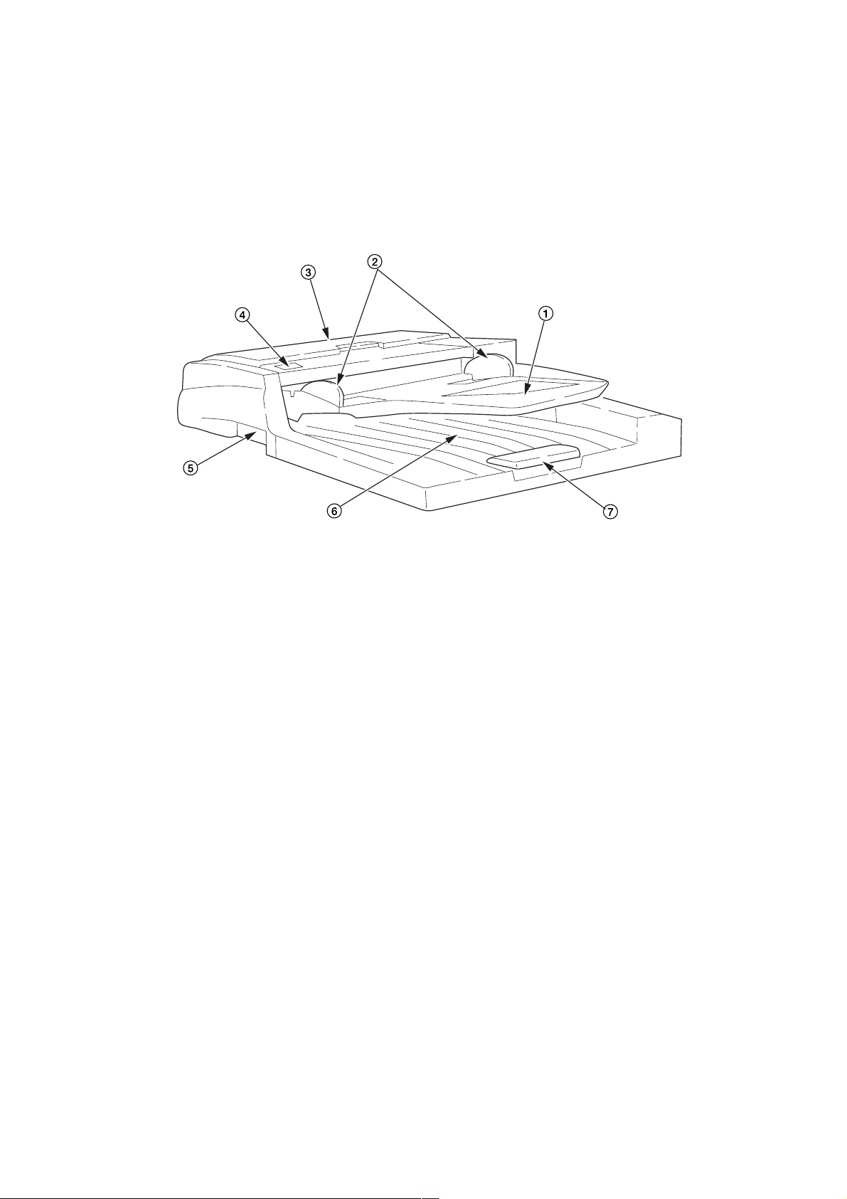
1-1-2 Parts names and their functions
(1) Parts names
Figure 1-1-1
1 Original table
2 Original insert guides
3 DF original reversing cover
4 Original set indicator
5 Original eject cover
6 DF opening/closing lever
7 Ejection extension
1-1-2
Page 11
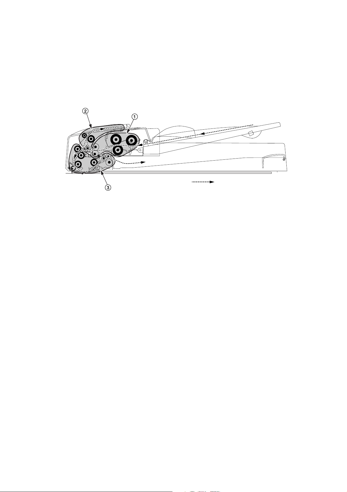
1-1-3 Machine cross section
3C0
Paper and original path
Figure 1-1-2 Machine cross section
1 Original feed section
2 Original switchback section
3 Original conveying section
1-1-3
Page 12
3C0
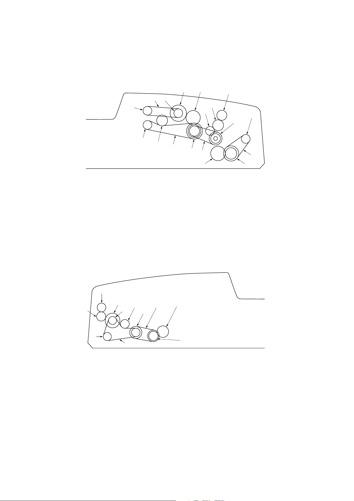
1-1-4 Drive system
(1) Drive system
6
1
Figure 1-1-3 Drive system (inside rear of machine)
1 Original feed motor pulley
2 Pulley 35/22/22
3 Idle gear 26
4 Original feed clutch gear
5 DF original feed pulley 18
6 DF forwarding pulley 18
7 Tension pulley
8 Original feed drive belt
9 DF forwarding belt
9
7
5
43
#
@
!
0
8
2
$
&
As viewed from machine rear
0 DF registration pulley 28/18
! Idle gear 15
@ Idle gear 20
# Switch back gear 18
$ DF registration drive belt
% Gear 22/35
^ Original conveying motor pulley
& Gear 28
* Original conveying drive belt 1
^
*
%
8
7
6
5
9
0
1
4
!
Figure 1-1-4 Drive system (inside front of machine)
1 Lower original conveying pulley 25/18
2 Gear 18/25
3 Eject gear 18
4 Middle original conveying pulley 18
5 Upper original conveying pulley 18
6 JAM release gear 24
3
2
As viewed from machine front
7 Joint gear 14
8 JAM release gear 14
9 Tension pulley
0 Eject drive belt
! Conveying drive belt 2
1-1-4
Page 13
1-2-1 Installation environment
1. Installation location (Be based on the copier establishment place.)
• Avoid direct sunlight or bright lighting. Ensure that the photoconductor will not be exposed to direct sunlight or other
strong light when removing paper jams.
• Avoid extremes of temperature and humidity, abrupt ambient temperature changes, and hot or cold air directed onto
the machine.
• Avoid dust and vibration.
• Choose a surface capable of supporting the weight of the machine.
• Place the machine on a level surface (maximum allowance inclination: 1° ).
• Avoid air-borne substances that may adversely affect the machine or degrade the photoconductor, such as
mercury, acidic of alkaline vapors, inorganic gasses, NOx, SOx gases and chlorine-based organic solvents.
• Select a room with good ventilation.
3C0
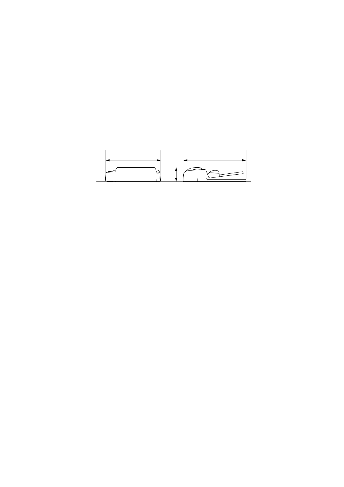
b
c
3
a: 553 mm/21
b: 478 mm/18
c: 137 mm/5
/4"
13
/16"
3
/8"
Figure 1-2-1 Installation dimensions
a
1-2-1
Page 14
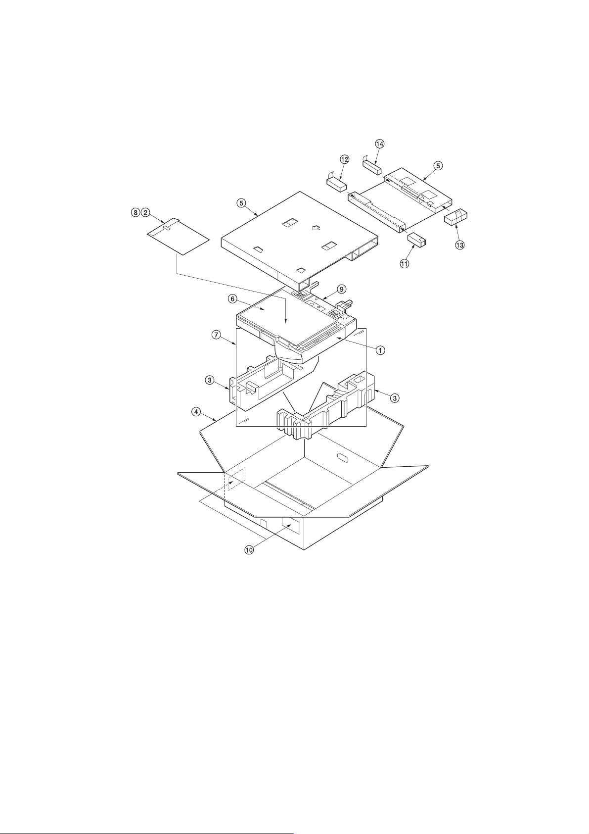
1-3-1 Unpacking and installation
(1) Unpacking
3C0
Figure 1-3-1 Unpacking
1 Document feeder
2 Installation guide
3 Bottom pad
4 Outer case
5 Upper pad
6 Eject pad
7 Plastic sheet (1300 × 1300)
8 Plastic bag
9 Plastic bag (200 × 200)
0 Bar code labels
! Front A pad
@ Front B pad
# Rear A pad
$ Rear B pad
1-3-1
Page 15
1-4-1 Maintenance mode
The copier is equipped with a maintenance function which can be used to maintain and service the machine.
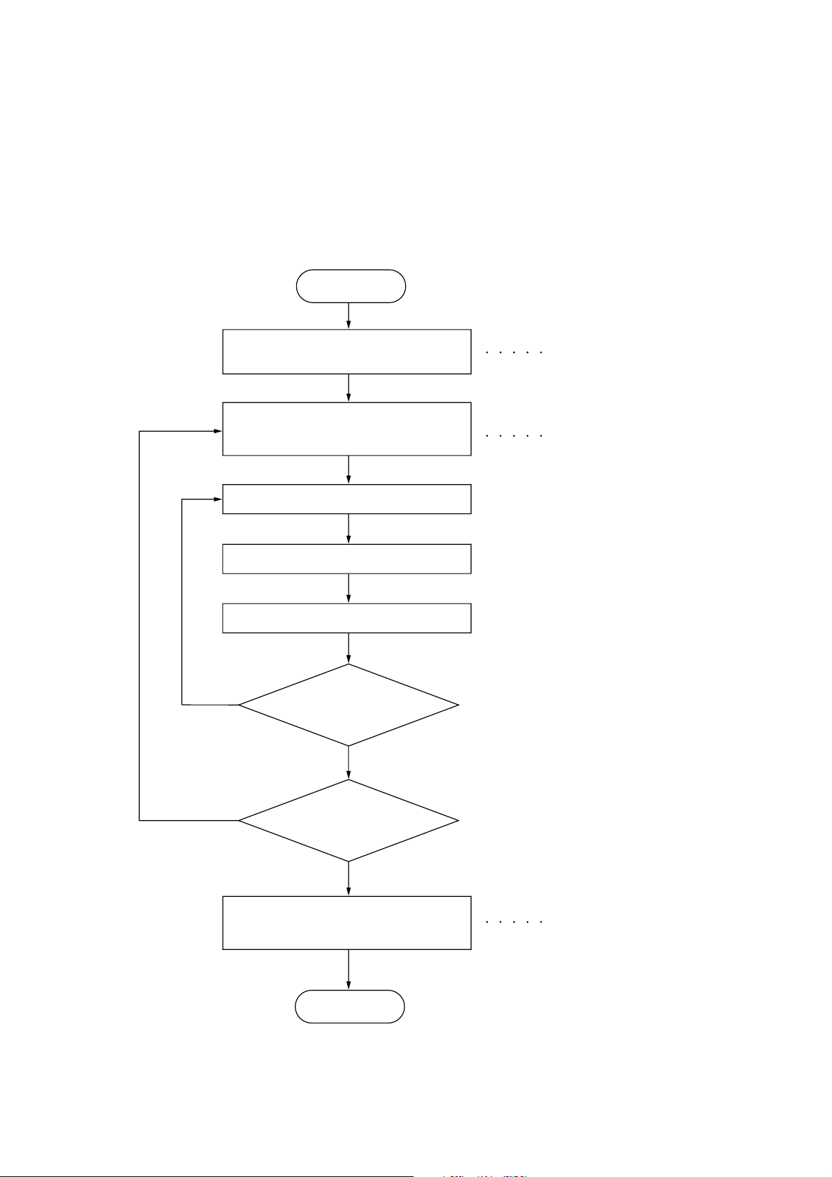
(1) Executing a maintenance item
Start
3C0
Yes
Enter “10871087” using
the numeric keys.
Enter the maintenance item
number using the cursor up/down keys
or numeric keys.
Press the start key.
The selected maintenance item is run.
Press the stop/clear key.
Repeat the same
maintenance item?
Maintenance mode is entered.
The maintenance item is
selected.
Yes
No
Run another maintenance
item?
No
Enter “001” using the cursor
up/down keys or numeric keys
and press the start key.
End
Maintenance mode is exited.
1-4-1
Page 16
3C0
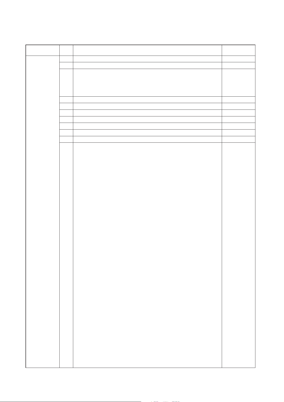
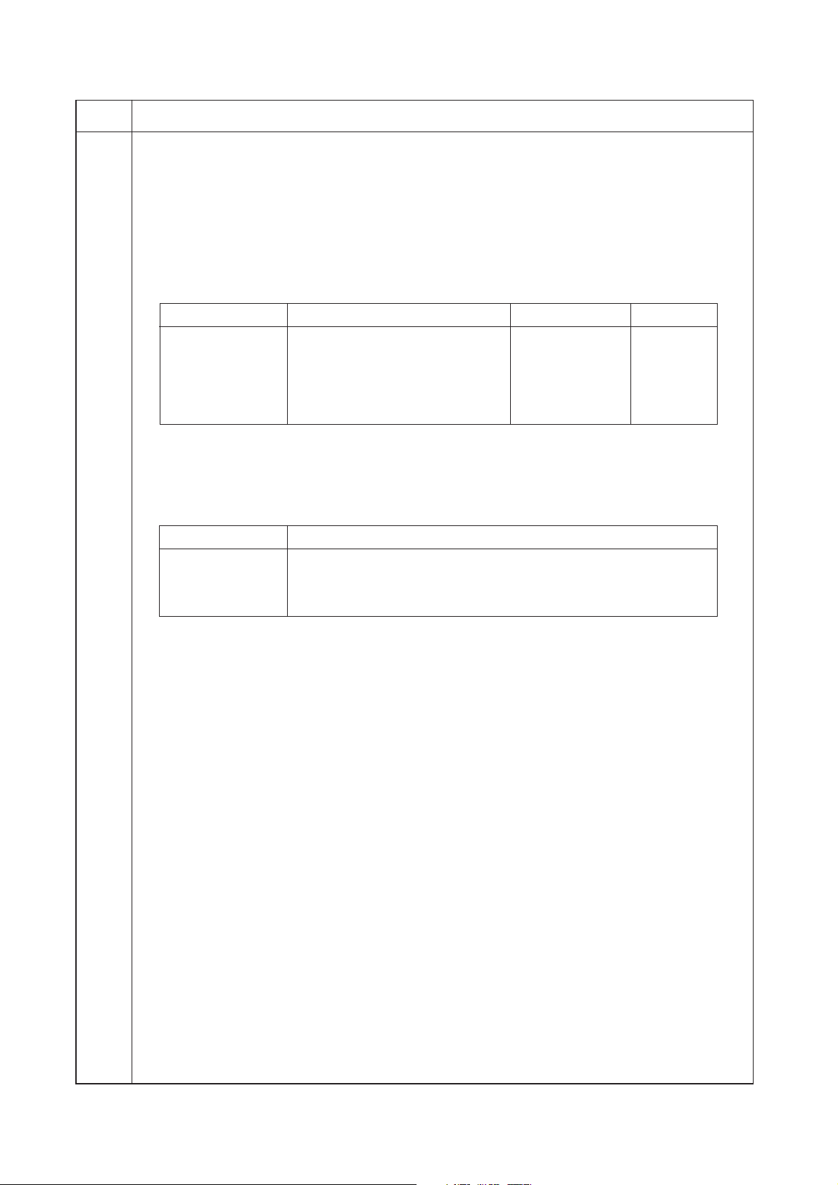
(2) Maintenance mode item list
Section
DF U068 Adjusting the scanning position for originals from the DF 0
Item
No. setting*
U070 Adjusting the DF magnification 0
U071 Adjusting the DF scanning timing
• DF leading edge registration 8 (black and
• DF trailing edge registration 0
U072 Adjusting the DF center line 0
U074 Adjusting the DF input light luminosity (black and white copiers only) 1
U203 Operating DF separately —
U243 Checking the operation of the DF motors, solenoids and clutch —
U244 Checking the DF switches —
U263 Setting the paper ejection when copying from the DF (color copiers only)
U404 Adjusting margins for scanning an original from the DF —
Maintenance item contents
Initial
white copiers)
0 (color copiers)
TRAY (NORMAL)
* Initial setting for executing maintenance item U020
1-4-2
Page 17
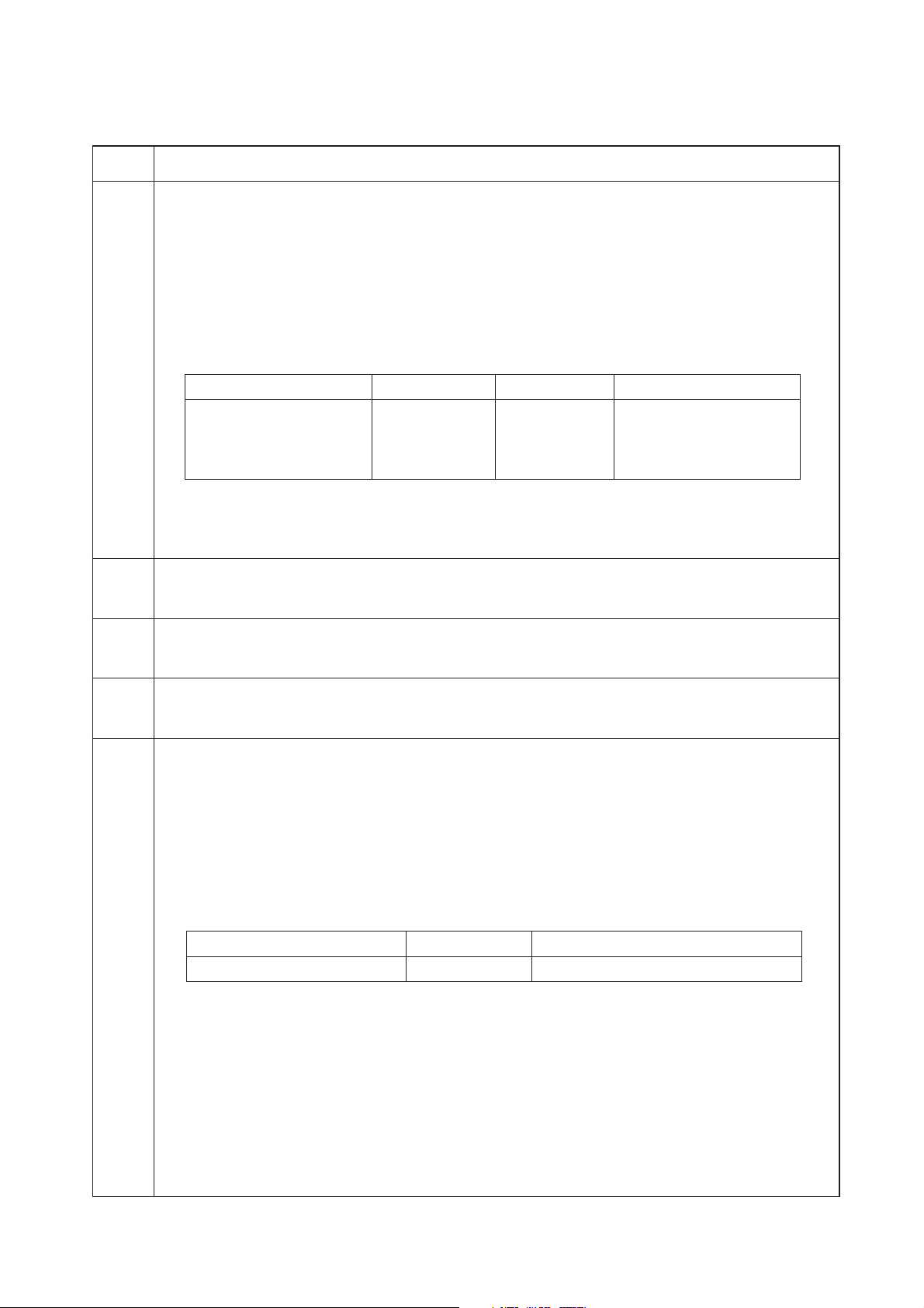
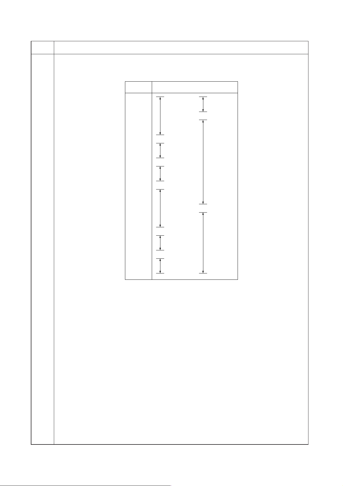
(3) Contents of maintenance mode items
3C0
Maintenance
item No.
U068 Adjusting the scanning position for originals from the DF
Description
Adjusts the position for scanning originals from the DF.
Purpose
Used when there is a regular error between the leading edges of the original and the copy image.
Method
Press the start key. The screen for executing is displayed.
Setting
1. Change the setting using the cursor up/down keys (in the case of black and white copiers).
Change the setting using the cursor left/right keys (in the case of color copiers).
Description Setting range Initial setting Change in value per step
Scanning position –2 to +3 0 0.254 mm (in the case of
–9 to +9 0 0.169 mm (in the case of
Increasing the setting moves the image backward, and decreasing it moves the image forward.
2. Press the start key. The value is set.
Completion
Press the stop/clear key. The screen for selecting a maintenance item No. is displayed.
U070 Adjusting the DF magnification
Adjustment
See pages 1-6-8.
U071 Adjusting the DF scanning timing
Adjustment
See page 1-6-10.
U072 Adjusting the DF center line
Adjustment
See page 1-6-9.
U074 Adjusting the DF input light luminosity (black and white copiers only)
Description
Adjusts the luminosity of the exposure lamp for scanning originals from the DF.
Purpose
Used if the exposure amount differs significantly between when scanning an original on the contact glass and
when scanning an original from the DF (installed to the black and white copiers).
Method
Press the start key. The screen for executing is displayed.
Setting
1. Change the setting using the cursor up/down keys.
Description Setting range Initial setting
DF input light luminosity 0 to 8 1
Increasing the setting makes the luminosity higher, and decreasing it makes the luminosity lower.
2. Press the start key. The value is set.
Interrupt copy mode
While this maintenance item is being performed, copying from an original can be made in interrupt copy mode.
Completion
Press the stop/clear key at the screen for selecting an item. The screen for selecting a maintenance item No. is
displayed.
Description
black and white copiers)
color copiers)
1-4-3
Page 18
3C0
Maintenance
item No.
U203 Operating DF separately
Description
Simulates the original conveying operation separately in the DF.
Purpose
To check the DF.
Method (in the case of black and white copiers)
1. Press the start key. The screen for selecting an item is displayed.
2. Place an original in the DF if running this simulation with paper.
3. Select the item to be operated. The selected item is displayed in reverse.
4. Select the magnification using the cursor up/down keys.
Display Operation Setting range Initial setting
ADF With paper, single-sided original 50 to 200 (%) 100
RADF With paper, double-sided original 50 to 200 (%) 100
ADF (NON-P) Without paper, single-sided original 50 to 200 (%) 100
RADF (NON-P) Without paper, double-sided original 50 to 200 (%) 100
5. Press the start key. The operation starts for the selected magnification.
6. To stop continuous operation, press the stop/clear key.
Method (in the case of color copiers)
1. Press the start key. The screen for selecting an item is displayed.
2. Place an original in the DF if running this simulation with paper.
3. Select the item to be operated using the cursor up/down keys. The selected item is displayed in reverse.
Display Operation
ADF With paper, single-sided original
RADF With paper, double-sided original
ADF (NON-P) Without paper, single-sided original (continuous operation)
RADF (NON-P) Without paper, double-sided original (continuous operation)
4. Press the start key. The operation starts.
5. To stop continuous operation, press the stop/clear key.
Completion
Press the stop/clear key when the operation stops. The screen for selecting a maintenance item No. is
displayed.
Description
(continuous operation)
(continuous operation)
1-4-4
Page 19

3C0
Maintenance
item No.
U243 Checking the operation of the DF motors, solenoids and clutch
Description
Turns the motors, solenoids or clutch in the DF on.
Purpose
To check the operation of the DF motors, solenoids and clutch .
Method
1. Press the start key. The screen for selecting an item is displayed.
2. Select the item to be operated (in the case of black and white copiers).
Select the item to be operated using the cursor up/down keys (in the case of color copiers).
The selected item is displayed in reverse and the operation starts.
Display Motors, solenoids and clutch Operation In operation
F MOT Original feed motor (OFM) In operation
C MOT Original paper conveying motor (OCM) In operation
FD CL Original feed clutch (OFCL) On for 0.5 s
EJ SL Eject feedshift solenoid (EFSSOL) On for 0.5 s
RJ SL Switchback feedshift solenoid (SBFSSOL) On for 0.5 s
FD SL Original feed solenoid (OFSOL) On and off
RP SL Switchback pressure solenoid (SBPSOL) On and off
3. To turn each motor off, press the stop/clear key.
Completion
Press the stop/clear key when operation stops. The screen for selecting a maintenance item No. is displayed.
U244 Checking the DF switches
Description
Displays the status of the respective switches in the DF.
Purpose
To check if respective switches in the DF operate correctly.
Start
1. Press the start key. The screen for selecting an item is displayed.
2. Select the type of switches (SW or VR) to be checked (in the case of black and white copiers).
Select the type of switches (SW or VR) to be checked using the cursor up/down keys (in the case of color
copiers).
The screen for executing each item is displayed.
Display Type of switches
SW On/off switches
VR Volume switch
Description
Method for the on/off switches (SW)
1. Turn the respective switches on and off manually to check the status.
If the on-status of a switch is detected, the corresponding switch is displayed in reverse.
Display Switches
SET SW Original set switch (OSSW)
FEED SW Original feed switch (OFSW)
REV SW Original switchback switch (OSBSW)
TMG SW DF timing switch (DFTSW)
SZ A SW Original size length switch (OSLSW)
2. To return to the screen for selecting an item, press the stop/clear key.
1-4-5
Page 20
3C0
Maintenance
item No.
U244 Method for the volume switch (VR)
1. Move the original insertion guides to check the detection status of the original size width switch.
The detected original width is displayed as a numerical value with the decimals omitted.
Numerical
103.936
104.448
139.264
139.776
146.432
146.994
value
000
49.664
50.176
61.440
61.952
····························································
Description
Original width to be detected
1
/2" × 81/2"
5
A5R
B5R
Folio/A4R
B4/B5
1
8
/2" × 14"/
1
8
/2" × 11"
197.120
197.632
197.720
223.232
256
CF (11"
A3/A4
×
15")
11"
11"
11"
×
×
×
17"/
15"/
81/2"
For example, if any value between 105 and 139 is displayed when the original insertion guides are adjusted
for A4R paper, it indicates that the original width is detected correctly.
2. To return to the screen for selecting an item, press the stop/clear key.
Completion
Press the stop/clear key at the screen for selecting an item. The screen for selecting a maintenance item No. is
displayed.
1-4-6
Page 21

3C0
Maintenance
item No.
U263 Setting the paper ejection when copying from the DF (color copiers only)
Description
Sets whether the copies will be ejected in the same or opposite order as the originals when copying from the
DF.
Purpose
Set according to the preference of the user when installed to the color copiers.
Method
Press the start key. The screen for selecting an item is displayed.
Setting
1. Use the cursor up/down keys to select the ejection order.
Display Setting
TRAY(NORMAL) Opposite order ejection (during side ejection)
TRAY(MEMORY) Same order ejection using memory copy (during side ejection)
ALL(MEMORY) Same order ejection using memory copy
Initial setting: TRAY(NORMAL)
2. Press the start key. The setting is set, and the screen for selecting a maintenance item No. is displayed.
Completion
To exit this maintenance item without changing the current setting, press the stop/clear key. The screen for
selecting a maintenance item No. is displayed.
U404 Adjusting margins for scanning an original from the DF
Adjustment
See page 1-6-12.
Description
1-4-7
Page 22

3C0
1-5-1 Original misfeed detection
(1) Original misfeed indication
When an original jams, the machine immediately stops operation and a message is shown on the copier operation panel. The
DF original set indicator also flashes red.
To remove the jammed original, open the DF or the DF original reversing cover.
To reset the original misfeed detection, open and close the DF or DF original reversing cover to turn DF safety switch 1 or
2 off and on.
• Misfeed in DF
Jam code 70
Jam code 71
Jam code 72
Jam code 73
Jam code 74
Jam code 75
Jam code 76
In the case of color copiers
In the case of black and
white copiers
(2) Original misfeed detection conditions
OFSW
OSBSW
DFTSW
Figure 1-5-1
1-5-1
Page 23

3C0
Section Jam code Description Conditions
Original
feed section
70
No original feed
In the primary original feed for the second original or after in
the 1 sided or 2 sided original mode, even if retry operation is
performed two times, primary original feed is not performed.
Original
conveying
section
71
72
73
An original jam in the
original feed section 1
An original jam in the
original feed section 2
An original jam in the
original conveying section
In the secondary original feed in the 1 sided original mode,
even if the specified number of pulses of the original feed
motor (OFM) passes after the original switchback switch
(OSBSW) turns on, the ON status of the DF timing switch
(DFTSW) is not detected.
In the secondary original feed in the 1 sided original mode,
even if the specified number of pulses of the original
conveying motor (OCM) passes after the DF timing switch
(DFTSW) turns on, the OFF status of the original feed switch
(OFSW) or the original switchback switch (OSBSW) is not
detected.
In the original switchback in the 2 sided original mode, even
if the specified number of pulses of the original feed motor
(OFM) passes after the original feed switch (OFSW) turns
on, the OFF status of the original feed switch (OFSW) is not
detected and the ON status of the original switchback switch
(OSBSW) is not detected.
In the secondary original feed in the 1 sided or 2 sided original mode, even if the specified number of pulses of the original conveying motor (OCM) passes after the DF timing
switch (DFTSW) turns on, the OFF status of the DF timing
switch (DFTSW) is not detected.
In the secondary original feed in the 1 sided or 2 sided original mode, before the specified number of pulses of the original conveying motor (OCM) passes after the DF timing
switch (DFTSW) turns on, the OFF status of the DF timing
switch (DFTSW) is detected.
Original
feed section
Original
switchback
section
74
75
76
An original jam remaining
after retries
An original jam in the
switchback section 1
An original jam in the
switchback section 2
In the secondary original feed in the 1 sided or 2 sided original mode, even if retry operation is performed five times,
secondary original feed is not performed.
In the original switchback in the 2 sided original mode, even
if the specified number of pulses of the original feed motor
(OFM) passes after the original switchback switch (OSBSW)
turns on, the OFF status of the original switchback switch
(OSBSW) is not detected.
In the secondary original feed in the 2 sided original mode,
even if the specified number of pulses of the original feed
motor (OFM) passes after the original conveying motor
(OCM) turns on, the ON status of the DF timing switch
(DFTSW) is not detected.
In the original switchback in the 2 sided original mode, even
if the specified number of pulses of the original feed motor
(OFM) passes after the original feed switch (OFSW) turns
on, the OFF status of the original feed switch (OFSW) is not
detected and the OFF status of the original switchback
switch (OSBSW) is detected.
While the back side of an original is being scanned in the 2
sided original mode, even if the specified number of pulses
of the original conveying motor (OCM) passes after the DF
timing switch (DFTSW) turns on, the ON status of the original
switchback switch (OSBSW) is not detected.
1-5-2
Page 24

(3) Original misfeeds
Problem Causes/check procedures Corrective measures
(1)
An original jams
when the main
switch is turned on.
A piece of paper torn from
an original is caught
around the original feed
switch.
Remove any found.
3C0
(2)
An original jams
during continuous
copying of multiple
originals.
Defective original feed
switch.
A piece of paper torn from
an original is caught
around the original
switchback switch.
Defective original
switchback switch.
A piece of paper torn from
an original is caught
around the DF timing
switch.
Defective DF timing
switch.
Defective original feed
switch.
Check if the original feed
motor or the original conveying motor malfunction.
Run maintenance item U244 and turn the original feed switch on
and off manually. Replace the original feed switch if indication of
the corresponding switch on the touch panel is not displayed in
reverse.
Remove any found.
Run maintenance item U244 and turn the original switchback
switch on and off manually. Replace the original switchback
switch if indication of the corresponding switch on the touch
panel is not displayed in reverse.
Remove any found.
Run maintenance item U244 and turn the DF timing switch on
and off manually. Replace the DF timing switch if indication of
the corresponding switch on the touch panel is not displayed in
reverse.
Run maintenance item U244 and turn the original feed switch on
and off manually. Replace the original feed switch if indication of
the corresponding switch on the touch panel is not displayed in
reverse.
Run maintenance item U243 and select the original feed motor/
original conveying motor on the touch panel to be turned on and
off. Check the status and remedy if necessary.
(3)
An original jams is
indicated during
copying (no original
feed).
Jam code 70
(4)
An original jams
during copying (a
jam in the original
feed/conveying section).
Jam code 71/72/73
Defective original feed
switch.
Check if the original feed
motor malfunctions.
Defective DF timing
switch.
Defective original feed
switch.
Run maintenance item U244 and turn the original feed switch on
and off manually. Replace the original feed switch if indication of
the corresponding switch on the touch panel is not displayed in
reverse.
Run maintenance item U243 and select the original feed motor
on the touch panel to be turned on and off. Check the status and
remedy if necessary.
Run maintenance item U244 and turn the DF timing switch on
and off manually. Replace the DF timing switch if indication of
the corresponding switch on the touch panel is not displayed in
reverse.
Run maintenance item U244 and turn the original feed switch on
and off manually. Replace the original feed switch if indication of
the corresponding switch on the touch panel is not displayed in
reverse.
1-5-3
Page 25

3C0
Problem Causes/check procedures Corrective measures
(4)
An original jams
during copying (a
jam in the original
feed/conveying section).
Jam code 71/72/73
Defective original
switchback switch.
Check if the original feed
motor malfunctions.
Run maintenance item U244 and turn the original switchback
switch on and off manually. Replace the original switchback
switch if indication of the corresponding switch on the touch
panel is not displayed in reverse.
Run maintenance item U243 and select the original feed motor
on the touch panel to be turned on and off. Check the status and
remedy if necessary.
(5)
An original jams
during copying (a
jam in the original
switchback section).
Jam code 75/76
Check if the DF original
feed pulley or the DF
separation pulley is deformed.
Check if the DF registration roller or the DF registration pulley is deformed.
Check if the lower original
conveying roller or the
front scanning pulley is
deformed.
Check if the original conveying motor malfunctions.
Defective original
switchback switch.
Defective DF timing
switch.
Check visually and replace the deformed pulley.
Check visually and replace the deformed pulley.
Check visually and replace the deformed pulley.
Run maintenance item U243 and select the original conveying
motor on the touch panel to be turned on and off. Check the status and remedy if necessary.
Run maintenance item U244 and turn the original switchback
switch on and off manually. Replace the original switchback
switch if indication of the corresponding switch on the touch
panel is not displayed in reverse.
Run maintenance item U244 and turn the DF timing switch on
and off manually. Replace the DF timing switch if indication of
the corresponding switch on the touch panel is not displayed in
reverse.
(6)
Original jams frequently.
Check if the original feed
motor malfunctions.
Check if the original conveying motor malfunctions.
An original outside the
specifications is used.
The DF forwarding pulleys,
DF original feed pulley or
DF switchback pulley is
dirty with paper powder.
The DF original feed pulley
and the DF separation pulley do not contact correctly.
Run maintenance item U243 and select the original feed motor
on the touch panel to be turned on and off. Check the status and
remedy if necessary.
Run maintenance item U243 and select the original conveying
motor on the touch panel to be turned on and off. Check the status and remedy if necessary.
Use only originals conforming to the specifications.
Clean with isopropyl alcohol.
Check and remedy.
1-5-4
Page 26

1-5-2 Image formation problems
3C0
(1) There is a regular error
between the centers of
the original and copy
image.
See page 1-5-6
(2) There is a regular error
between the leading
edges of the original
and copy image.
See page 1-5-6
(3) There is a regular error
between the trailing
edges of the original
and copy image.
See page 1-5-6
1-5-5
Page 27

3C0
(1) There is a regular
error between the
centers of the
original and copy
image.
Causes
1. Misadjusted DF center line.
(2) There is a regular
error between the
leading edges of
the original and
copy image.
Causes
1. Misadjusted DF center line.
Check procedures/corrective measures
Readjust the DF center line (see page 1-6-9).
Causes
1. Misadjusted DF original scanning start
position.
Causes
1. Misadjusted DF original scanning start
position.
(3) There is a regular
error between the
trailing edges of the
Causes
1. Misadjusted DF original scanning end
position.
original and copy
image.
Causes
1. Misadjusted DF original scanning end
position.
Check procedures/corrective measures
Readjust the DF original scanning start position (see page 1-6-10).
Check procedures/corrective measures
Readjust the DF original scanning end position (see page 1-6-11).
1-5-6
Page 28

1-5-3 Electrical problems
Problem Causes Check procedures/corrective measures
(1)
The original feed
motor does not
operate.
Defective original feed motor coil.
The connector terminals of
the original feed motor
make poor contact.
Check for continuity across the coil. If none, replace the original
feed motor.
Reinsert the connector. Also check for continuity within the connector cable. If none, remedy or replace the cable.
3C0
(2)
The original conveying motor does not
operate.
(3)
The original feed
solenoid does not
operate.
(4)
The switchback
feedshift solenoid
does not operate.
Defective DF driver PCB.
Defective original conveying motor coil.
The connector terminals of
the original conveying motor make poor contact.
Defective DF driver PCB.
Defective original feed solenoid coil.
The connector terminals of
the original feed solenoid
make poor contact.
Defective DF driver PCB.
Defective switchback
feedshift solenoid coil.
The connector terminals of
the switchback feedshift
solenoid make poor contact.
Check for continuity across the original feed motor coil and connector terminals. If good, replace the DF driver PCB.
Check for continuity across the coil. If none, replace the original
conveying motor.
Reinsert the connector. Also check for continuity within the connector cable. If none, remedy or replace the cable.
Check for continuity across the original conveying motor coil and
connector terminals. If good, replace the DF driver PCB.
Check for continuity across the coil. If none, replace the original
feed solenoid.
Reinsert the connector. Also check for continuity within the connector cable. If none, remedy or replace the cable.
Check if the original feed solenoid operates when CN5-B13 or
CN5-B12 on the DF driver PCB is low. If it does, replace the DF
driver PCB.
Check for continuity across the coil. If none, replace the
switchback feedshift solenoid.
Reinsert the connector. Also check for continuity within the connector cable. If none, remedy or replace the cable.
(5)
The eject feedshift
solenoid does not
operate.
(6)
The switchback
pressure solenoid
does not operate.
Defective DF driver PCB.
Defective eject feedshift
solenoid coil.
The connector terminals of
the eject feedshift solenoid
make poor contact.
Defective DF driver PCB.
Defective switchback pressure solenoid coil.
The connector terminals of
the switchback pressure
solenoid make poor contact.
Defective DF driver PCB.
Check if the switchback feedshift solenoid operates when CN5B8 on the DF driver PCB is low. If it does, replace the DF driver
PCB.
Check for continuity across the coil. If none, replace the eject
feedshift solenoid.
Reinsert the connector. Also check for continuity within the connector cable. If none, remedy or replace the cable.
Check if the eject feedshift solenoid operates when CN5-A7 on
the DF driver PCB is low. If it does, replace the DF driver PCB.
Check for continuity across the coil. If none, replace the
switchback pressure solenoid.
Reinsert the connector. Also check for continuity within the connector cable. If none, remedy or replace the cable.
Check if the switchback pressure solenoid operates when CN5A2 or CN5-A3 on the DF driver PCB is low. If it does, replace the
DF driver PCB.
1-5-7
Page 29

3C0
Problem Causes Check procedures/corrective measures
(7)
The original feed
clutch does not
operate.
Defective original feed
clutch coil.
The connector terminals of
the original feed clutch
make poor contact.
Check for continuity across the coil. If none, replace the original
feed clutch.
Reinsert the connector. Also check for continuity within the connector cable. If none, remedy or replace the cable.
(8)
A message indicating cover open is
displayed when the
DF is closed correctly.
(9)
An original jams
when the main
switch is turned on.
Defective DF driver PCB.
The connector terminals of
DF safety switch 1 make
poor contact.
Defective DF safety switch
1.
A piece of paper torn from
an original is caught
around the original feed
switch.
Defective original feed
switch.
A piece of paper torn from
an original is caught
around the original
switchback switch.
Defective original
switchback switch.
Check if the original feed clutch operates when CN5-A5 on the
DF driver PCB is low. If it does, replace the DF driver PCB.
Reinsert the connector. Also check for continuity within the connector cable. If none, remedy or replace the cable.
Check for continuity across the contacts of the switch. If none
when the switch is on, replace DF safety switch 1.
Remove any found.
Run maintenance item U244 and turn the original feed switch on
and off manually. Replace the original feed switch if indication of
the corresponding switch on the touch panel is not displayed in
reverse.
Remove any found.
Run maintenance item U244 and turn the original switchback
switch on and off manually. Replace the original switchback
switch if indication of the corresponding switch on the touch
panel is not displayed in reverse.
A piece of paper torn from
an original is caught
around the DF timing
switch.
Defective DF timing
switch.
The surface facing the DF
timing switch is soiled.
Remove any found.
Run maintenance item U244 and turn the DF timing switch on
and off manually. Replace the DF timing switch if indication of
the corresponding switch on the touch panel is not displayed in
reverse.
Check if the projection at the center of the conveying cover that
is facing the DF timing switch is soiled with paper powder. If so,
clean it.
1-5-8
Page 30

1-5-4 Mechanical problems
Problem Causes/check procedures Corrective measures
(1)
No primary original
feed.
The surfaces of the DF forwarding pulleys,
DF original feed pulley or DF separation pulley are dirty with paper powder.
3C0
Check and clean them with isopropyl alcohol if they are dirty.
(2)
No secondary original
feed.
(3)
Originals jam.
Check if the DF original feed pulley or the
DF forwarding pulley is deformed.
Electrical problem with the following clutch
or solenoid:
• Original feed solenoid
• Original feed clutch
The DF registration pulley and the DF registration roller do not contact each other correctly.
Originals outside the specifications are used.
The surfaces of the DF forwarding pulleys,
DF original feed pulley or DF separation pulley are dirty with paper powder.
The DF original feed pulley and the DF
separation pulley do not contact each other
correctly.
If so, replace (see page 1-6-3).
See pages 1-5-7 and 8.
Check visually and remedy if necessary.
Use only originals conforming to the specifications.
Check and clean them with isopropyl alcohol if they are dirty.
Check visually and remedy if necessary.
1-5-9
Page 31

1-6-1 Precautions for assembly and disassembly
(1) Precautions
• Be sure to turn the main switch off and disconnect the power plug before starting disassembly.
• When handling PCBs, do not touch connectors with bare hands or damage the board.
• Do not touch any PCB containing ICs with bare hands or any object prone to static charge.
• Use the following testers when measuring voltages:
Hioki 3200
Sanwa MD-180C
Sanwa YX-360TR
Beckman TECH300
Beckman DM45
Beckman 330*
Beckman 3030*
Beckman DM850*
Fluke 8060A*
Arlec DMM1050
Arlec YF1030C
* Capable of measuring RMS values.
3C0
1-6-1
Page 32

3C0
(2) Running a maintenance item
Start
Enter “10871087” using
the numeric keys.
Enter the maintenance item
number using the cursor up/down keys
The selected maintenance item is run.
Yes
Yes
or numeric keys.
Press the start key.
Press the stop/clear key.
Repeat the same
maintenance item?
No
Run another maintenance
item?
Maintenance mode is entered.
The maintenance item is
selected.
No
Enter “001” using the cursor
up/down keys or numeric keys
and press the start key.
End
Maintenance mode is exited.
1-6-2
Page 33

1-6-2 Original feed section
(1) Detaching and refitting the DF forwarding pulley and DF feed pulley
Follow the procedure below to clean or replace the DF forwarding pulley or DF feed pulley.
Procedure
1. Open the DF original reversing cover.
2. Remove the two screws holding the upper
original feed cover and then the cover.
• Detaching the DF forwarding pulley
3. Remove the stop ring at the machine front
and then remove the bushing.
4. Pull out the forwarding shaft toward the rear
side of the machine and slide the bushing.
5. Remove the DF forwarding pulley from the
forwarding shaft.
• Detaching the DF feed pulley
6. Remove the stop ring at the machine front
and then remove the bushing.
7. Remove the stop ring at the machine rear.
8. Pull out the front original feed shaft toward
the rear side of the machine and slide the
bushing.
9. Remove the DF feed pulley from the front
original feed shaft.
10. Clean or replace the DF forwarding pulley
and the DF feed pulley.
11. Refit all the removed parts.
* When refitting the DF forwarding pulley and
DF feed pulley, ensure that the notches in the
pulleys are aligned with the projections on the
one-way clutches.
Front original
feed shaft
One-way clutch
Bushing
Stop ring
3C0
DF feed pulley
DF forwarding pulley
Stop ring
Stop ring
bushing
bushing
Machine
front
DF forwarding belt
One-way clutch
Bushing
forwarding
shaft
Machine
rear
Figure 1-6-1
1-6-3
Page 34

3C0
(2) Detaching and refitting the DF separation pulley
Follow the procedure below to clean or replace the DF separation pulley.
Procedure
1. Open the DF original reversing cover.
2. Remove the DF front and rear covers.
3. Remove the two screws holding the upper
original feed cover and then the cover.
Screws
Upper original
feed cover
4. Remove the four connectors and then
remove the wires from the two wire clamps.
Figure 1-6-2
Connectors
Wire clamps
1-6-4
Connectors
Figure 1-6-3
Page 35

5. Remove the two screws holding the solenoid
bracket and then the bracket.
6. Remove the screw and then remove the feed
guide pin.
Screw
3C0
Feed guide pin
7. Remove the E-ring and then the original feed
clutch.
8. Remove the E-ring and then remove the
bushing.
Screws
E-ring
Solenoid bracket
Figure 1-6-4
E-ring
Original feed clutch
Figure 1-6-5
Bushing
1-6-5
Page 36

3C0
g
9. Open the registration guide and remove the
guide.
10. Remove the two screws holding the upper
feed guide plate and then the plate.
Registration guide
Upper original feed
guide plate
Screw
Screw
11. Remove the two screws holding the original
feed lift and then the lift.
12. Remove the screw holding the separation
guide and then the guide.
Figure 1-6-6
Screw
Separation guide
Screw
1-6-6
Screw
Ori
inal feed lift
Figure 1-6-7
Page 37

13. Remove the separation shaft from the
separation pulley arms.
14. Remove the stopper and torque limitter from
the separation shaft and then remove the DF
separation pulley.
15. Clean or replace the DF separation pulley.
16. Refit all the removed parts.
3C0
Torque limitter
DF separation
pulley
Stopper
Separation shaft
Separation pulley
arms
Figure 1-6-8
1-6-7
Page 38

3C0
(3) Adjusting the DF magnification
Adjust magnification in the auxiliary scanning direction if magnification is incorrect when the DF is used.
U053
(See the service manual
of the copier.)
U065(main scanning
direction)
(See the service manual
of the copier.)
U065(auxiliary scanning
direction)
(See the service manual
of the copier.)
U070
Caution
Before making the following adjustment, ensure that the above adjustments have been made in maintenance mode.
Procedure
Main scanning
direction
Start
Auxiliary
scanning
Enter maintenance mode.
Enter “070” using the numeric keys.
Press the start key.
direction
Original
Copy
example 1
Figure 1-6-9
Copy
example 2
Press the interrupt key.
Place an original on the DF
and make a test copy.
Is the image correct?
Yes
Press the stop/clear key to
exit maintenance mode.
End
Press the start key.
The new setting
is stored.
For copy example 1, increase
the value using the cursor up key
(cursor right key).
No
For copy example 2, decrease
the value using the cursor down key
(cursor left key).
* ( ) indicates the case of color copiers.
Setting range: –25 – +25 (in the case of
black and white copiers)
–2.5 – +2.5 (in the case of
color copiers)
Initial setting: 0
Changing the value by 1 changes
the magnification by 0.1%.
Increasing the value makes
the image longer, and decreasing it
make the image shorter.
1-6-8
Page 39

3C0
(4) Adjusting the DF center line
Perform the following adjustment if there is a regular error between the centers of the original and the copy image when
the DF is used.
U034
(See the service manual
of the copier.)
(See the service manual
U067
U072
of the copier.)
Caution
Before making the following adjustment, ensure that the above adjustments have been made in maintenance mode.
Procedure
Reference
Start
Enter maintenance mode.
Copy
example 2
Enter “072” using the numeric keys.
Original Copy
example 1
Figure 1-6-10
Press the start key.
Select the item to be adjusted.
Press the interrupt key.
Place an original on the DF
and make a test copy.
Is the image correct?
Yes
Press the stop/clear key to
exit maintenance mode.
End
Press the start key.
The new setting
is stored.
For copy example 1, increase
the value using the cursor up key
(cursor right key).
No
For copy example 2, decrease
the value using the cursor down key
(cursor left key).
* ( ) indicates the case of color copiers.
Setting range: –39 – +39 (in the case of
black and white copiers)
–20 – +20 (in the case of
color copiers)
Initial setting: 0
Changing the value by 1 moves
the center line by 0.17 mm.
1-6-9
Page 40

3C0
(5) Adjusting the scanning start position
Perform the following adjustment if there is a regular error between the leading or trailing edges of the original and the
copy image.
U034
(See the service manual
of the copier.)
(See the service manual
U066
U071
of the copier.)
Caution
Before making the following adjustment, ensure that the above adjustments have been made in maintenance mode.
(5-1) Adjusting the DF leading edge registration
Procedure
Start
Enter maintenance mode.
Enter “071” using the numeric keys.
Original
Copy
example 1
Copy
example 2
Figure 1-6-11
Press the start key.
Select “LEAD EDGE ADJ”.
Press the interrupt key.
Place an original on the DF
and make a test copy.
Is the image correct?
Yes
Press the stop/clear key to
exit maintenance mode.
End
Press the start key.
The new setting
is stored.
For copy example 1, increase
the value using the cursor up key
(cursor right key).
No
For copy example 2, decrease
the value using the cursor down key
(cursor left key).
* ( ) indicates the case of color copiers.
Setting range: –32 – +32
Initial setting: 8 (in the case of black and
white copiers)
Initial setting: 0 (in the case of color copiers)
Changing the value by 1 moves
the leading edge by 0.17 mm.
Increasing backward and decreasing it moves
the image forward.
1-6-10
Page 41

(5-2) Adjusting the DF trailing edge registration
Procedure
Start
Enter maintenance mode.
3C0
Enter “071” using the numeric keys.
Press the start key.
Select “TRAIL EDGE ADJ”.
Press the interrupt key.
Place an original on the DF
and make a test copy.
Is the image correct?
Yes
Press the stop/clear key to
exit maintenance mode.
End
Original Copy
example 1
Figure 1-6-12
Press the start key.
The new setting
is stored.
For copy example 1, increase
the value using the cursor up key
(cursor right key).
No
For copy example 2, decrease
the value using the cursor down key
(cursor left key).
* ( ) indicates the case of color copiers.
Setting range: –32 – +32
initial setting: 0
Changing the value by 1 moves
the trailing edge by 0.17 mm.
Increasing backward and decreasing it moves
the image forward.
Copy
example 2
1-6-11
Page 42

3C0
(6) Adjusting the margins for scanning the original from the DF
Perform the following adjustment if margins are not correct.
(See the service manual
U402
of the copier.)
(See the service manual
U403
U404
of the copier.)
Caution
Before making the following adjustment, ensure that the above adjustments have been made in maintenance mode.
Procedure
DF leading edge margin (3 ± 1.5 mm [2 ± 1.0 mm])
Ejection direction
Start
Enter maintenance mode.
(reference)
* [ ] indicates the case of
color copiers.
DF left margin
(2 ± 1.0 mm)
DF right margin
(2 ± 1.0 mm)
DF trailing edge margin
(2 ± 1.0 mm)
Figure 1-6-13
Enter “404” using the numeric keys.
Press the start key.
Select the item to be adjusted.
Press the interrupt key.
Place an original on the DF
and make a test copy.
Are the margins correct?
Yes
Yes
Proceed to another mode?
No
Press the stop/clear key to
exit maintenance mode.
A MARGIN (LEFT/mm): DF left margin
B MARGIN (TOP/mm): DF leading edge margin
C MARGIN (RIGHT/mm): DF right margin
D MARGIN (BOTTOM/mm): DF trailing edge margin
* ( ) indicates the case of color copiers.
Press the start key.
The new setting
is stored.
Change the setting.
Increasing the value using the cursor
No
up key (cursor right key) makes the
margin wider.
Decreasing the value using the
cursor down key (cursor left key)
makes the margin narrower.
* ( ) indicates the case of color
copiers.
Setting range (initial setting)
DF left margin: 0 – +10.0 (2.0 [2.0])
DF leading edge margin: 0 – +10.0 (3.0 [2.0])
DF right margin: 0 – +10.0 (2.0 [2.0])
DF trailing edge margin: 0 – +10.0 (2.0 [2.0])
Changing the value by one moves
the margin by 0.5 mm [0.1 mm] for all.
* [ ] indicates the case of color copiers.
1-6-12
End
Page 43

3C0
2-1-1 Original feed section
The original feed section consists of the parts shown in Figure. An original placed on the original table is conveyed to the
original switchback section or the original conveying section.
Figure 2-1-1 Original feed section
1 Original table
2 DF forwarding pulleys
3 DF original feed pulley
4 DF separation pulley
5 DF original feed upper guide
6 DF original feed lower guide
7 Original stopper
8 DF registration pulley
OFSW
9 DF registration roller
0 DF registration guide
! Original set switch (OSSW)
@ Original feed switch (OFSW)
# Original feed clutch (OFCL)
$ Original feed solenoid (OFSOL)
% Original feed lift
OFCL
OSSW
OFM
OFSOL
CN6-B5
CN5-B12 -
CN5-B13
CN5-A5
CN6-B2
DFDPCB
CN5-B1 -
Figure 2-1-2 Original feed section block diagram
CN5-B6
2-1-1
Page 44

3C0
(1) Original feed timing
OFSOL A
OFSOL R
Fwd. rotation
Rev. rotation
OSBSW
DFTSW
10 ms 150 ms
OFCL
OffOFM
OFSW
OCM
200 ms
298 P* 20 ms
150 ms
*Burst of OFM pulses
Timing chart 2-1-1 Original feed (in simple-sided original mode)
a The OFSOL A signal goes high for 10 ms and then turns off for 200 ms. It goes high again for 150 ms and the original
feed solenoid (OFSOL) turns on, raising the original feed lift to convey the original forward.
b 298 OFM pulses after the leading edge of the original turns the original feed switch (OFSW) on, the original feed
clutch (OFCL) and original feed motor (OFM) turn off. 20 ms later, the rotation of the motor switches to the reverse
direction and secondary original feed is performed by rotation of the DF registration roller.
c Simultaneously as the trailing edge of the original turns the original feed switch (OFSW) off, the original feed motor
(OFM) turns off.
d After ejection of the original, as the original conveying motor (OCM) turns off, the OFSOL R signal turns on for 150
ms and the original feed solenoid (OFSOL) turns off.
2-1-2
Page 45

2-1-2 Original switchback section
The original switchback section consists of the parts shown in Figure. The original from the original feed section or
original conveying section is reversed and conveyed to the original conveying section.
Figure 2-1-3 Original switchback section
1 Switchback pulley
2 Switchback roller
3 Switchback feedshift guide
4 Left switchback guide
5 Switchback guide
6 Original switchback switch (OSBSW)
7 Switchback feedshift solenoid (SBFSSOL)
8 Switchback pressure solenoid (SBPSOL)
3C0
SBPSOL SBFSSOL
OSBSW
CN5-A2 -
CN5-A3
CN6-A5
CN5-B8
DFDPCB
Figure 2-1-4 Original switchback section block diagram
2-1-3
Page 46

3C0
(1) Operation of original switchback
In the double-sided original mode, the switchback feedshift solenoid (SBFSSOL) turns on, changing the position of the
switchback feedshift guide. This switches the path of the original to the original switchback section to where the original
is fed.
The switchback feedshift solenoid (SBFSSOL) then turns off, allowing the switchback feedshift guide to return to the
original position by which the path of the original is switched back to the original conveying section. The now reversed
original is carried to the original conveying section and the switchback pressure solenoid (SBPSOL) turns off, releasing
the switchback pulley to prevent an original jam in the original switchback section.
Switchback
pulley
Switchback feedshift guide
Figure 2-1-5
2-1-4
Page 47

3C0
2-1-3 Original conveying section
The original conveying section consists of the parts shown in Figure. Synchronized with the copier scanning operation,
the original is conveyed across the slit glass and ejected when scanning is complete.
In the double-sided original mode, the eject feedshift solenoid (EFSSOL) turns on, moving the eject feedshift guide to
switch the path of the original. When the scanning of the first face (reverse face) of the original is complete, the original is
conveyed to the original switchback section again.
Figure 2-1-6 Original conveying section
1 Upper original conveying pulley
2 Upper original conveying roller
3 Lower original conveying roller
4 Front scanning pulley
5 Middle original conveying roller
6 Middle original conveying pulley
7 Eject pulley
8 Eject roller
OCM
DFTSW
9 Original conveying guide
0 Eject feedshift guide
! Upper eject guide
@ Lower eject guide
# Slit glass (copier)
$ DF timing switch (DFTSW)
% Eject feedshift solenoid
(EFSSOL)
EFSSOL
CN5-A13
CN5-A8 -
CN6-B14
DFDPCB
CN5-A7
Figure 2-1-7 Original conveying section block diagram
2-1-5
Page 48

3C0
(1) Original switchback/conveying timing
Fwd. rotation
Rev. rotation
OffOFM
OFSW
SBFSSOL
SBPSOL A
SBPSOL R
OSBSW
OCM
EFSSOL
DFTSW
298 P
100 ms
*1
20 ms
*1
135 P
Scanning speed
30 ms
*2
78 P
Scanning speed
*1 Burst of OFM pulses
*2 Burst of OCM pulses
Timing chart 2-1-2 Reversing the first face of the original
a During primary original feed, when the original feed switch (OFSW) turns on, the switchback feedshift solenoid
(SBFSSOL) also turns on, changing the position of the switchback feedshift guide. This switches the path of the
original to the original switchback section.
b 298 OFM pulses plus 20 ms after the original feed switch (OFSW) turns on, the rotation of the original feed motor
(OFM) switches to the reverse direction and the original is conveyed to the switchback section by the rotation of the
switchback roller.
c Simultaneously as the original feed switch (OFSW) turns off, the switchback pressure solenoid (SBPSOL) turns on to
operate the switchback pulley.
d When the trailing edge of the original turns the original switchback switch (OSBSW) off, the switchback feedshift
solenoid (SBFSSOL) turns off, the switchback feedshift guide returns to the original position.
e 135 OFM pulses after the original switchback switch (OSBSW) turns off, the original feed motor (OFM) turns off. 100
ms later, the original feed motor (OFM) rotates forward, switching the rotational direction of the switchback roller. The
original in the original switchback section is then reversed and conveyed to the original conveying section.
f Simultaneously as the original feed motor (OFM) starts rotating forward, the original conveying motor (OCM) turns on
to convey the original onto the slit glass. The eject feedshift solenoid (EFSSOL) simultaneously turns on, changing
the position of the eject feedshift guide. This switches the path of the original to the original switchback section.
g When the original is conveyed onto the slit glass, the DF timing switch (DFTSW) turns on. 78 OCM pulses later, the
switchback pressure solenoid (SBPSOL).
h 30 ms after the switchback pressure solenoid (SBPSOL) turns off, the original feed motor (OFM) turns off.
2-1-6
Page 49

Fwd. rotation
OFM
Rev. rotation
OFSW
SBFSSOL
135 P
100 ms
*1
Scanning request signal: On
Scanning speed
*1
327 P
100 ms
3C0
SBPSOL
SBPSOL
OSBSW
OCM
EFSSOL
DFTSW
362 P
30 ms
*1
*2
78 P
Scanning speed
30 ms
2252 P*2 + 30 ms
*1 Burst of OFM pulses
*2 Burst of OCM pulses
Timing chart 2-1-3 Reversing of the second face of the original and ejection
a 362 OFM pulses after the scanning of the first face (reverse face) of the original completes and the DF timing switch
(DFTSW) turns off, the switchback pressure solenoid (SBPSOL) turns on, operating the switchback pulley.
b When the trailing edge of the original turns the original switchback switch (OSBSW) off, the eject feedshift solenoid
(EFSSOL) turns off and the eject feedshift guide returns to the original position, switching the path of the original to
the eject section. Simultaneously, the switchback feedshift solenoid (SBFSSOL) turns off and the switchback
feedshift guide returns to the original position.
c 30 ms after the original switchback switch (OSBSW) turns off, the original conveying motor (OCM) turns off.
d 135 OFM pulses after the original switchback switch (OSBSW) turns off, the original feed motor (OFM) turns off.
e 100 ms after the original feed motor (OFM) turns off, the motor starts rotating forward, switching the rotational
direction of the switchback roller. The original in the original switchback section is then reversed and conveyed to the
original conveying section.
f 327 OFM pulses plus 100 ms after the original feed motor (OFM) turns off, the motor starts rotating forward again and
the original conveying motor (OCM) turns on simultaneously, conveying the original onto the slit glass.
g 78 OFM pulses after the original is conveyed onto the slit glass and the DF timing switch (DFTSW) turns on, the
switchback pressure solenoid (SBPSOL) turns off.
h 30 ms after the switchback pressure solenoid (SBPSOL) turns off, the original feed motor (OFM) turns off.
i When the scanning request signal turns on, scanning of the second face (front face) of the original starts.
j 2252 OCM pulses plus 30 ms after scanning of the second face (front face) of the original completes and the DF
timing switch (DFTSW) turns off, the original conveying motor (OCM) turns off, completing the ejection of the original.
2-1-7
Page 50

2-2-1 Electrical parts layout
(1) PCBs
2
1
Machine front Machine inside Machine rear
Figure 2-2-1 PCBs
1. DF driver PCB (DFDPCB) ........................... Controls electrical components of the DF.
2. Original set LED PCB (OSLEDPCB) ........... Indicates presence of originals on the DF or an original jam.
3C0
2-2-1
Page 51

3C0
(2) Switches and sensors
2
3
4
8
5
6
7
1
Machine front
Machine inside
Machine rear
Figure 2-2-2 Switches and sensors
1. DF safety switch 1 (DFSSW1) ..................... Breaks the safety circuit when the DF is opened; resets original misfeed
detection.
2. DF safety switch 2 (DFSSW2) ..................... Breaks the safety circuit when the DF original switchback cover is
opened; resets original misfeed detection.
3. Original set switch (OSSW) ......................... Detects the presence of an original.
4. Original feed switch (OFSW) ....................... Detects primary original feed end timing.
5. Original switchback switch (OSBSW) .......... Detects an original misfeed in the original switchback section.
6. DF timing switch (DFTSW) .......................... Detects the original scanning timing.
7. Original size length switch (OSLSW) ........... Detects the length of the original.
8. Original size width switch (OSWSW) ........... Detects the width of the original.
2-2-2
Page 52

(3) Motors
3C0
1
2
Machine front
Machine inside
Machine rear
Figure 2-2-3 Motors
1. Original feed motor (OFM) ........................... Drives the original feed and switchback sections.
2. Original conveying motor (OCM) ................. Drives the original conveying section.
2-2-3
Page 53

3C0
(4) Clutches and solenoids
4
5
2
3
1
Machine front Machine inside
Machine rear
Figure 2-2-4 Clutches and solenoids
1. Original feed solenoid (OFSOL) .................. Operates the paper feed lift.
2. Switchback feedshift solenoid
(SBFSSOL) .................................................. Operates the switchback feedshift guide.
3. Eject feedshift solenoid (EFSSOL) .............. Operates the eject feedshift guide.
4. Switchback pressure solenoid (SBPSOL) .... Operates the switchback pulley.
5. Original feed clutch (OFCL) ......................... Controls the drive of the DF original feed pulley.
2-2-4
Page 54

2-3-1 DF driver PCB
Copier
24V
5V
DFSSW2 OPEN
DFSSW1 OPEN
5 V DC
Motor
driver
IC
Motor
driver
IC
DFDPCB
24 V DC
DFSSW2
24V
24V (VEN)
24V
OCM A
OCM B
OCM A_
OCM B_
24V
OFM A
OFM B
OFM A_
OFM B_
3C0
DFSSW1
2
1
3
1
OCM
OFM
2
3
Clutch,
Driver
OSWSW
Driver
Driver
Solenoids
Switches
LED
Figure 2-3-1 DF driver PCB block diagram
The DF driver PCB (DFDPCB) consists of the motor driver ICs and other driver circuits. The motor driver ICs are controlled
by various motor control signals from the copier to drive the original feed motor (OFM) and the original conveying motor
(OCM). The other driver circuits drive the clutch, solenoids, and LED based on the control signals from the copier and
function as buffers that output the signals detected by the switches to the copier. The copier supplies DC 24 V and DC 5 V
power sources. The DC 24 V is the power source for driving the motors, clutch, and solenoids. The DC 5 V is the power
source for driving the switches and LED. The power supply line of the DC 24 V is connected through the DF safety switch
1 (DFSSW1) and the DF safety switch 2 (DFSSW2) to each load to provide a safety circuit that interrupts power supply to
each load when the DF is opened or closed or the DF original reversing cover is opened or closed.
2-3-1
Page 55

3C0
B-1
A-13
B-1
A-15
CN5
22
21
B-13
A-1
CN2
CN6
B-15
A-1
CN3
2
14
1
13
Figure 2-3-2 DF driver PCB silk-screen diagram
CN4
41
CN1
91
10 2
2
1
2-3-2
Page 56

Connector Pin No. Signal I/O Voltage Description
CN1
Connected
to the
copier.
1 24 V I 24 V DC 24 V DC supply
2 24 V I 24 V DC 24 V DC supply
3 PG - Ground Ground for 24 V DC supply
4 PG - Ground Ground for 24 V DC supply
5 NC - - Not used
6 NC - - Not used
7 5V I 5 V DC 5 V DC supply
8 5V I 5 V DC 5 V DC supply
9 SG - Ground Ground for 5 V DC supply
10 SG - Ground Ground for 5 V DC supply
3C0
CN2
Connected
to the
copier.
CN3
Connected
to the
copier.
1 OCM M1 I 0/5 V DC (pulse) OCM control signal (M1)
2 OCM M2 I 0/5 V DC (pulse) OCM control signal (M2)
3 OCM M3 I 0/5 V DC (pulse) OCM control signal (M3)
4 NC - - Not used
5 NC - - Not used
6 OCM Vref I Analog OCM current control voltage
7 OCM CWB I 0/5 V DC OCM rotation direction switching signal
8 OCM CLK I 0/5 V DC (pulse) OCM drive clock signal
9 OCM RET I 0/5 V DC OCM control signal
10 OCM ENABLE I 0/5 V DC OCM enable signal
11 OFM CWB I 0/5 V DC OFM rotation direction switching signal
12 OFM CLK I 0/5 V DC (pulse) OFM drive clock signal
13 OFM RET I 0/5 V DC OFM control signal
14 OFM ENABLE I 0/5 V DC OFM enable signal
15 OFSOL(ACT) I 0/24 V DC OFSOL: actuate
16 OFSOL(RET) I 0/24 V DC OFSOL: return
17 SBFSSOL I 0/24 V DC SBFSSOL: On/Off
RESERVE(SOL)
18
19 EFSSOL I 0/24 V DC EFSSOL: On/Off
20 OFCL I 0/24 V DC OFCL: On/Off
21 SBPSOL(ACT) I 0/24 V DC SBPSOL: actuate
22 SBPSOL(RET) I 0/24 V DC SBPSOL: return
1 OSSW O 0/5 V DC OSSW: On/Off
2 OFSW O 0/5 V DC OFSW: On/Off
3 OSBSW O 0/5 V DC OSBSW: On/Off
RESERVE (SW)
4
5 OSLSW O 0/5 V DC OSLSW: On/Off
6 DFSSW1 O 0/5 V DC DFSSW1: On/Off
7 DFSSW2 O 0/5 V DC DFSSW2: On/Off
8 OSWSW O Analog OSWSW detection voltage
OSLED(GREEN)
9
10 OSLED(RED) I 0/5 V DC OSLED (red): On/Off
11 DF SHORT O 0/5 V DC DF installed/not installed detection signal
12 RESERVE(SW) - - Not used
13 DFTSW O 0/5 V DC DFTSW: On/Off
14 NC - - Not used
- - Not used
- - Not used
I 0/5 V DC OSLED (green): On/Off
CN4
Connected
to the
copier.
1 24 V(VEN) - 0/24 V DC 24 V DC supply via DFSSW1 and DFSSW2
2 24 V - 24 V DC 24 V DC supply
DFSSW2 OPEN
3
4
DFSSW1 OPEN
- 0/24 V DC DFSSW2: On/Off
- 0/24 V DC DFSSW1: On/Off
2-3-3
Page 57

3C0
Connector Pin No. Signal I/O Voltage Description
CN5
Connected
to the
switchback
pressure
solenoid,
original
feed clutch,
eject
feedshift
solenoid,
original
conveying
motor,
original
feed motor,
switchback
feedshift
solenoid,
original
feed
solenoid.
A-1 24 V O 24 V DC
A-2 SBPSOL(ACT) O 0/24 V DC SBPSOL: actuate
A-3 SBPSOL(RET) O 0/24 V DC SBPSOL: return
A-4 24 V O 24 V DC
A-5 OFCL O 0/24 V DC OFCL: On/Off
A-6 24 V O 24 V DC
A-7 EFSSOL O 0/24 V DC EFSSOL: On/Off
A-8 OCM ACOM O 24 V
24 V(VEN)
A-9 OCM BCOM O 24 V
24 V(VEN)
A-10 OCM A O 0/24 V DC (pulse) OCM motor coil energization pulse (A)
A-11 OCM B O 0/24 V DC (pulse) OCM motor coil energization pulse (B)
A-12 OCM A_ O 0/24 V DC (pulse) OCM motor coil energization pulse (A_)
A-13 OCM B_ O 0/24 V DC (pulse) OCM motor coil energization pulse (B_)
B-1 OFM ACOM O 24 V
24 V(VEN)
B-2 OFM BCOM O 24 V
24 V(VEN)
B-3 OFM A O 0/24 V DC (pulse) OFM motor coil energization pulse (A)
B-4 OFM B O 0/24 V DC (pulse) OFM motor coil energization pulse (B)
B-5 OFM A_ O 0/24 V DC (pulse) OFM motor coil energization pulse (A_)
B-6 OFM B_ O 0/24 V DC (pulse) OFM motor coil energization pulse (B_)
B-7 24 V - 24 V DC
B-8 SBFSSOL O 0/24 V DC SBFSSOL: On/Off
B-9 24 V - - Not used
B-10
B-11 24 V - 24 V DC
B-12 OFSOL(ACT) O 0/24 V DC OFSOL: actuate
B-13 OFSOL(RET) O 0/24 V DC OFSOL: return
RESERVE(SOL)
- - Not used
24 V DC supply for SBPSOL (via DFSSW1 and DFSSW2)
24 V DC supply for OFCL (via DFSSW1 and DFSSW2)
24 V DC supply for EFSSOL (via DFSSW1 and DFSSW2)
24 V DC supply for OCM (via DFSSW1 and DFSSW2)
24 V DC supply for OCM (via DFSSW1 and DFSSW2)
24 V DC supply for OFM (via DFSSW1 and DFSSW2)
24 V DC supply for OFM (via DFSSW1 and DFSSW2)
24 V DC supply for SBFSSOL (via DFSSW1 and DFSSW2)
24 V DC supply for SBPSOL (via DFSSW1 and DFSSW2)
CN6
Connected
to the
original
switchback
switch,
original size
length
switch,
original size
width
switch,
original set
switch,
original
feed switch,
original set
LED PCB.
A-1 - - - Not used
A-2 - - - Not used
A-3 - - - Not used
A-4 SG - Ground Ground for 5 V DC supply
A-5 OSBSW I 0/5 V DC OSBSW: On/Off
A-6 5V O 5 V DC 5 V DC supply for OSBSW
A-7 SG - Ground Ground
A-8 OSLSW I 0/5 V DC OSLSW: On/Off
A-9 5V O 5 V DC 5 V DC supply for OSLSW
A-10 SG - Ground Ground
A-11 OSWSW I Analog OSWSW detection voltage
A-12 5V O 5 V DC 5 V DC supply for OSWSW
A-13 SG - - Not used
A-14
A-15 5V - - Not used
B-1 5V O 5 V DC 5 V DC supply for OSSW
B-2 OSSW I 0/5 V DC OSSW: On/Off
B-3 SG - Ground Ground
B-4 5V O 5 V DC 5 V DC supply for OFSW
B-5 OFSW I 0/5 V DC OFSW: On/Off
B-6 SG - Ground Ground
B-7 OSLED(RED) O 0/5 V DC OSLED (red): On/Off
B-8 SG - Ground Ground
B-9 OSLED(GN) O 0/5 V DC OSLED (green): On/Off
B-10 5V - - Not used
B-11 DOCSW - - Not used
B-12 SG - - Not used
B-13 5V O 5 V DC 5 V DC supply for DFTSW
B-14 DFTSW I 0/5 V DC DFTSW: On/Off
B-15 SG - Ground Ground
RESERVE(SW)
- - Not used
2-3-4
Page 58

3C0
Copier signal wait condition
298 P
5099 P
Secondary original feed start
Primary original feed endDF start
OFM CN5-B3, B4, B5, B6
OCM
CN5-A10, A11, A12, A13
OFSW CN6-B5
OSBSW CN6-A5
OFSOL A
DFTSW
CN5-B12
OFSOL R CN5-B13
OFCL CN5-A5
CN6-B14
" original in single-sided original mode
2
/
1
××
××
× 8
Timing chart No. 1 Original feed operation 1: Feeding an A4/11"
2-4-1
Page 59

3C0
Secondary original
feed start
Start of primary feed
for next original
Primary original
feed end
DF start
OFM
OFSOL A CN5-B12
OFSOL R CN5-B3
OFCL CN5-A5
DFTSW
Copier signal wait condition
298 P
298 P
5099 P
OSBSW
CN5-B3, B4, B5, B6
OCM
CN5-A10, A11, A12, A13
OFSW CN6-B5
CN6-A5
CN6-B14
" originals successively in single-sided original mode
2
/
1
××
××
× 8
2-4-2
Timing chart No. 2 Original feed operation 2: Feeding two A4/11"
Page 60

Secondary original
feed start (reverse face)
Secondary original
feed start (reverse
face)
Secondary original
feed start (front face)
Secondary original feed start
(front face)
Switchback
operation start
Switchback
operation start
Switchback
operation end
Switchback
operation end
Switchback
operation end
Switchback
operation end
Start of primary feed
for next original
Primary original
feed end
Primary original
feed end
DF start
Copier signal
wait condition
OFM
100 ms
135 P
135 P
135 P
135 P
OFSOL A CN5-B12
OFSOL R CN5-B13
OFCL CN5-A5
CN5-B3, B4, B5, B6
OCM
CN5-A10, A11, A12, A13
OFSW CN6-B5
OSBSW CN6-A5
DFTSW CN6-B14
SBFSSOL CN5-B8
EFSSOL CN5-A7
SBPSOL A CN5-A2
SBPSOL R CN5-A3
3C0
××
××
× 11" originals successively in double-sided original mode
"
2
/
1
Timing chart No. 3 Original feed operation 3: Feeding two A4R/8
2-4-3
Page 61

3C0
Maintenance parts list
Maintenance part name
Name used in service manual Name used in parts list
DF forwarding pulley PULLEY,LEADING FEED 3BC07010 4 5
DF feed pulley PULLEY,SEPARATION 3BC07020 4 6
DF separation pulley PULLEY,SEPARATION 3BC07020 4 27
DF registration roller ROLLER,REGISTRATION 3BC08050 6 56
Front reading pulley FRONT PULLEY,READING 3AL08480 6 7
DF registration pulley PULLEY B,REGISTRATION 3BC08220 5 12
Original feed switch SWITCH L,FEED 63227150 4 17
Lower original conveying roller LOWER ROLLER,CONVEYING 3AL08112 6 32
Upper original conveying roller UPPER ROLLER,CONVEYING 3AL08161 6 30
Upper original conveying pulley UPPER PULLEY,CONVEYING 3AL08140 1 5
Original conveying guide GUIDE,CONVEYING 3AL08033 6 1
Original conveying pulley cover COVER,CONVEYING PULLEY 3AL08302 6 4
Middle original conveying roller INNER ROLLER,CONVEYING 3BC08150 6 19
Middle original conveying pulley INNER PULLEY,CONVEYING 3AL08100 6 52
Eject pulley PULLEY,EJECT 3AL08170 5 11
Switchback roller ROLLER,LOOP 3AL10020 5 6
Eject pulley PULLEY,EJECT 3AL08170 5 20
Eject roller ROLLER,EJECT 3AL08130 6 39
Original size length switch filter FILTER CF SENSOR 78706241 3 16
Slit glass* CONTACT GLASS,ADF 2AV12250 9 [11] 19 [61]
Covers Covers - - -
Original holder mat MAT,ORIGINAL HOLDER 3AL04060 1 16
Original holder sheet SHEET,ORIGINAL HOLDER 3AL08401 6 10
Original size indicator sponge* SPONGE,ORIGINAL SIZE INDICATOR 35912531 9 [11] 52 [63]
Part No. Fig. No. Ref. No.
* Equipped with the copier. [ ] indicates the case of color copiers.
2-4-4
Page 62

Periodic maintenance procedures
3C0
Section
Test copy and Perform at the maximum Test copy Every service
test print copy size
Section
Original feed DF forwarding pulley Replace or clean Every 100,000 counts Clean with alcohol when visiting 1-6-3
section the user.
Section
Original Lower original conveying Clean Every service Clean with alcohol or a dry cloth.
conveying roller
section Upper original conveying Clean Every service Clean with alcohol or a dry cloth.
Maintenance
part/location
Maintenance
part/location
DF feed pulley Replace or clean Every 100,000 counts Clean with alcohol when visiting 1-6-3
DF separation pulley Replace or clean Every 100,000 counts Clean with alcohol when visiting 1-6-4
DF registration roller Clean Every service Clean with alcohol or a dry cloth.
Front reading pulley Clean Every service Clean with alcohol or a dry cloth.
DF registration pulley Check or clean Every service Clean with alcohol or a dry cloth
Original feed switch Check or clean Every service Clean with airbrush or a dry cloth.
Maintenance
part/location
roller
Upper original conveying Check or clean Every service Clean with alcohol or a dry cloth
pulley if it is dirty.
Original conveying guide Clean Every service Clean with alcohol or a dry cloth.
Original conveying pulley Clean Every service Clean the opposite side of the DF
cover timing switch with alcohol or a dry
Middle original conveying Clean Every 400,000 counts Clean with alcohol (Remove the
roller front, rear and right covers and
Middle original conveying Clean Every 400,000 counts Clean with alcohol (Remove the
pulley front, rear and right covers and
Eject pulley Check or clean Every service Clean with alcohol or a dry cloth
Method Maintenance cycle Points and cautions Page
Method Maintenance cycle Points and cautions Page
the user.
the user.
if it is dirty.
Method Maintenance cycle Points and cautions Page
cloth.
original conveying pulley mount
plate).
original conveying pulley mount
plate).
if it is dirty.
Section
Original Original size length switch Clean Every service Clean with alcohol.
Table Filter
Maintenance
part/location
Method Maintenance cycle Points and cautions Page
2-4-5
Page 63

3C0
Section
Covers Covers Clean Every service Clean with alcohol.
Section
Other Original holder mat Clean Every service Clean with alcohol or a dry cloth.
Maintenance
part/location
Slit glass* Clean Every service Clean with alcohol or a dry cloth.
Maintenance
part/location
Original holder sheet Clean Every service Clean with alcohol or a dry cloth.
Original size indicator Clean Every service Clean with alcohol or a dry cloth.
sponge*
Method Maintenance cycle Points and cautions Page
Method Maintenance cycle Points and cautions Page
* Equipped with the copier.
2-4-6
Page 64

CN5(B-1)
CN5(B-2)
CN5(B-3)
CN5(B-4)
CN5(B-5)
CN5(B-6)
CN5(A-8)
CN5(A-9)
CN5(A-10)
CN5(A-11)
CN5(A-12)
CN5(A-13)
24V
SBPSOL(ACT)
SBPSOL(RET)
24V
OFCL
24V
EFSSOL
SBFSSOL
24V
OFSOL (RET)
OFSOL (ACT)
24V
OCM A
OCM B
OCM A_
OCM B_
OCM ACOM 24V(VEN)
OCM BCOM 24V(VEN)
OFM B_
OFM A_
OFM B
OFM A
OFM BCOM 24V(VEN)
OFM ACOM 24V(VEN)
24V (VEN)
24V
DFSSW2 OPEN
DFSSW1 OPEN
1
2
3
3
2
1
CN5(B-11)
CN5(B-12)
CN5(B-13)
CN5(B-7)
CN5(B-8)
CN5(A-6)
CN5(A-7)
CN5(A-4)
CN5(A-5)
CN5(A-1)
CN5(A-2)
CN5(A-3)
CN4-1
CN4-2
CN4-3
CN4-4
NC:
CN1-5
CN1-6
CN2-4
CN2-5
CN3-14
CN6(A-1)
CN6(A-2)
CN6(A-3)
CN6(B-3)
CN6(B-2)
CN6(B-1)
CN6(B-4)
CN6(B-5)
CN6(B-6)
CN6(A-4)
CN6(A-5)
CN6(A-6)
CN6(A-10)
CN6(A-11)
CN6(A-12)
CN6(A-7)
CN6(A-8)
CN6(A-9)
CN6(B-7)
CN6(B-8)
CN6(B-9)
CN6(B-15)
CN6(B-14)
CN6(B-13)
SG
OSSW
5V
5V
OFSW
SG
SG
OSBSW
5V
SG
OSWSW
5V
SG
OSLSW
5V
OSLED (RED)
SG
OSLED (GN)
SG
DFTSW
5V
DFDPCB
OCM
OFSOL
SBPSOL
OFCL
SBFSSOL
EFSSOL
OFM
DFSSW1
DFSSW2
DFTSW
OSLSW
OSBSW
OFSW
OSSW
OSWSW
OSLED
PCB
B
A
1234 567891011
123456789101112
1234 567891011
123456789101112
Connected to the copier
NC
FG
FG
FG
SG
SG
5V
5V
PG
PG
24V
24V
CN1-10
CN1-9
CN1-8
CN1-7
CN1-4
CN1-3
CN1-2
CN1-1
NC
NC
OSLED(RED)
OSLED(GREEN)
SBPSOL(RET)
SBPSOL(ACT)
OFCL
EFSSOL
RESERVE(SOL)
SBFSSOL
OFSOL(RET)
OFSOL(ACT)
OFM ENABLE
OSBSW
OFSW
OSSW
RESERVE(SW)
RESERVE(SW)
DF SHORT
OSWSW
DFSSW2
DFSSW1
OSLSW
DFTSW
OFM RET
FOMT CLK
OFM CWB
OCM ENABLE
OCM RET
OCM CLK
OCM CWB
OCM Vref
OCM M3
OCM M2
OCM M1
CN3-3
CN3-2
CN2-13
CN3-10
CN3-9
CN2-22
CN2-21
CN2-20
CN2-19
CN2-18
CN2-17
CN2-16
CN2-15
CN2-14
CN2-12
CN2-11
CN2-10
CN2-9
CN2-8
CN2-7
CN2-6
CN2-3
CN2-2
CN2-1
CN3-1
CN3-4
CN3-12
CN3-11
CN3-8
CN3-7
CN3-6
CN3-5
CN3-13
Connection diagram
3C0
2-4-7
Page 65

3C0
Wiring diagram
SBFSSOL
BE
C27
1
2
24V
SBFSSOL
C26
2
1
C5(B-8) GY
C5(B-7) GYBE
EFSSOL
BE
C25
1
2
24V
EFSSOL
C24
2
1
C5(A-7) GY
C5(A-6) GYBE
6
SG
1
C31-3 OE
C31-1 BE
C31-2 YW
321
5V
OSLSW
SG
OEYWBE
OSLSW
C31-6 OE
C31-5 GY
C31-4 BE
321
SG
OSWSW
5V
5V
1
C6(B-1) RD
C6(A-10) GY
C6(A-9) GY
C6(A-8) GY
C6(A-7) GY
432
5
5VSGOSWSW
OSLSW
C8-1 OE
C8-3 BE
C8-2 YW
C7-3 BE
C30
C31
OSWSW
OSSW
OSSW
SG
2
3
C23
C6(B-2) RD
C6(B-3) RD
C6(A-12) GY
C6(A-11) GY
C28
1
5V
C29
65432
C7-2 GY
C7-1 OE
C4-4 RD
DFSSW1
DFSSW1
DFSSW2
3P21
C4-3 RD
C4-1 RD
P2-2 RD
123
24V
24V(VEN)
DFSSW2
24V
24V(VEN)
2
P1-1 RD
C4-2 RD
P1
OSLEDPCB
OSLED(G
SG
OSLED(R
231
C6(B-7) GY
C6(B-8) GY
C6(B-9) GY
P1-3 RD
P2-3 RD
P2-1 RD
P1-2 RD
123
4
24V(VEN)
24V
DFSSW2
DFSSW1
(CN4)
A-14
A-13
A-15
RESERVE(SW)
5V
SG
5V
OSSWSG5V
B-3
B-2
B-1
C23-2 WH
C23-3 WH
C23-1 RD
C15-1 RD
C15-2 GY
C15-3 GY
A-12
A-11
A-13
OCM B
OCM B_
OCM A_
OFM A
OFM BCOM
OFM ACOM
B-1
B-3
B-2
C9-6 RD
C9-5 GY
C9-4 GY
OFSW
5V
SG
OFSW
2
1
3
C22
C6(B-4) BK
C6(B-5) BK
C6(B-6) BK
C101-11
C101-10
C101-9
123456789
24V
24VPGPG5VNCNC5VSGSG
C4
C28-1 RD
C28-2 GY
C28-3 GY
C28-4 GY
C28-5 GY
A-7
A-8
A-9
A-10
A-11
A-12
5VSGOSWSW
5V
OFSW
SG
OSLED(RD)SGOSLED(GN)5VDOCSW SG5V
B-9
B-8
B-7
B-6
B-5
B-4
C21-1 BK
C21-2 BK
C21-3 BK
C22-3 GY
C22-2 GY
C15-4 GY
C15-5 GY
C15-6 GY
C24-1 GY
C24-2 GY
A-9
A-5
A-6
A-7
A-8
A-10
OCM ACOM
OCM BCOM
OCM A
OFCL
24V
EFSSOL
OFM A_
OFM B_
24V
SBFSSOL
OFM B
24V
B-9
B-7
B-6
B-8
B-5
B-4
C9-3 GY
C9-2 GY
C9-1 GY
C26-2 GY
C26-1 GY
5V
OSBSW
SG
OSBSW
OFSOL
GNBNRD
2
3
OFSOL(ACT)
OFSOL(RET)
24V
C21
2
1
31
C5(B-13) GY
C5(B-12) GY
C101-8
C101-7
C101-6
C28-6 GY
C18-1 GY
C18-2 GY
C18-3 GY
A-2
A-3
A-4
A-5
A-6
SG
OSBSW
5VSGOSLSW
DFTSW
B-14
B-13
B-12
B-10
B-11
C17-1 GY
C22-1 GY
C11-1 GY
C11-2 GY
C13-1 GY
C13-2 GY
C13-3 GY
A-1
A-2
A-3
A-4
SBPSOL(RET)
24V
24V
SBPSOL(ACT)
OFSOL(RET)
OFSOL(ACT)
24V
RESERVE(SOL)
B-13
B-12
B-11
B-10
C19-3 GY
C19-2 GY
C19-1 GY
C18
C6(A-6) GY
1
C6(A-5) GY
2
C6(A-4) GY
3
C20
C19
C5(B-11) GY
C101-5
C101-4
10
(CN1)
C1
(CN3)
C3
A-1
(CN6)
C6
SG
B-15
C17-2 GY
C17-3 GY
(CN2)
C2
(CN5)
C5
DFTSW
SG
DFTSW
5V
OCM
SBPSOL
OFCL
OFM
OSSW
1
OFSW
2
OSBSW
3
4
RESERVE(SW)
5
OSLSW
DFSSW1
6
DCSSW2
7
8
OSWSW
OSLED(GN)
9
OSLED(RD)
10
DF SHORT
11
12
RESERVE(SW)
DFTSW
13
14
NC
OCM M1
1
OCM M2
2
OCM M3
3
NC
4
NC
5
OCM Vref
6
OCM CWB
7
OCM CLK
8
OCM RET
9
10
OCM ENABLE
OFM CWB
11
OFM CLK
12
OFM RET
13
14
OFM ENABLE
OFSOL(ACT)
15
OFSOL(RET)
16
SBFSSOL
17
RESERVE(SOL)
18
EFSSOL
19
OFCL
20
SBPSOL(ACT)
21
SBPSOL(RET)
22
DFDPCB
C17
C6(B-15) GY
3
C6(B-14) GY
2
C6(B-13) GY
1
BK
WE
RD
BE
YW
OE
RD
BN
GN
BK
BK
BK
WE
RD
BE
YW
OE
C102-4
C102-3
C102-2
C102-5
C102-11
C102-10
C102-9
C102-8
C104-3
C104-2
C102-7
C102-6
C102-12
C103-11
C103-10
C103-9
C103-8
C103-7
C103-6
C103-5
C103-4
C103-3
C103-2
C103-1
C104-12
C104-11
C104-10
C104-9
C104-8
C104-7
C104-6
C104-5
C104-4
C16
1
OCM ACOM
2
OCM BCOM
3
OCM A
4
OCM B
OCM A_
5
6
OCM B_
C14
1
24V
SBPSOL(ACT)
2
3
SBPSOL(RET)
C12
1
24V
2
OFCL
C10
1
OFM ACOM
2
OFM BCOM
3
OFM A
4
OFM B
OFM A_
5
6
OFM B_
C1-10
C1-9
C1-8
C1-7
C1-4
C1-3
C1-2
C1-1
C3-3
C3-2
C3-1
C3-4
C3-12
C3-11
C3-8
C3-7
C3-6
C3-5
C3-13
C2-13
C2-12
C2-11
C2-10
C2-9
C2-8
C2-7
C2-6
C2-3
C2-2
C2-1
C3-10
C3-9
C2-22
C2-21
C2-20
C2-19
C2-18
C2-17
C2-16
C2-15
C2-14
C15
C13
C11
C9
M1
6
5
4
3
2
1
3
2
1
2
1
6
5
4
3
2
1
C5(A-8) RD
C5(A-9) GY
C5(A-10) GY
C5(A-11) GY
C5(A-12) GY
C5(A-13) RD
C5(A-1) GY
C5(A-2) GY
C5(A-3) GY
C5(A-4) GY
C5(A-5) GY
C5(B-1) RD
C5(B-2) GY
C5(B-3) GY
C5(B-4) GY
C5(B-5) GY
C5(B-6) GY
1
FG
2
FG
3
NC
4
SG
5
C101 C102 C103 C104
SG
6
5V
7
5V
8
PG
9
PG
10
24V
11
24V
1
NC
2
OSBSW
3
OFSW
4
OSSW
5
RESERVE(SW)
6
RESERVE(SW)
DF SHORT
7
OSWSW
8
DFSSW2
9
10
DFSSW1
OSLSW
11
12
DFTSW
1
OFM RET
2
OFM CLK
3
OFM CWB
OCM ENABLE
4
5
OCM RET
OCM CLK
6
OCM CWB
7
8
OCM Vref
9
OCM M3
10
OCM M2
11
OCM M1
1
NC
OSLED(RED)
2
OSLED(GREEN)
3
SBPSOL(RET)
4
SBPSOL(ACT)
5
OFCL
6
EFSSOL
7
RESERVE(SOL)
8
SBFSSOL
9
OFSOL(RET)
10
11
OFSOL(ACT)
12
OFM ENABLE
AB
Connected to the copier
2-4-8
Page 66

KYOCERA MITA EUROPE B.V.
Hoeksteen 40, 2132 MS Hoofddorp,
The Netherlands
Phone: (020) 6540000
Home page: http://www.kyoceramita-europe.com
Email: info@kyoceramita-europe.com
KYOCERA MITA NEDERLAND B.V.
Hoeksteen 40, 2132 MS Hoofddorp,
The Netherlands
Phone: (020) 5877200
KYOCERA MITA (UK) LIMITED
8 Beacontree Plaza
Gillette Way,
Reading RG2 0BS UK
Phone: (0118) 931 1500
KYOCERA MITA ITALIA S.P.A.
Via Verdi 89/91 20063 Cernusco sul Naviglio
(Milano) Italy
Phone: 02-92179 1
S.A. KYOCERA MITA BELGIUM N.V.
Hermesstraat 8A, 1930 Zaventem, Belgium
Phone: (02) 7209270
KYOCERA MITA FRANCE S.A.
Parc les Algorithmes
SAINT AUBIN
91194 GIF-SUR-YVETTE
France
Phone: (01) 69852600
KYOCERA MITA ESPAÑA S.A.
Edificio Kyocera, Avda. De Manacor Nº2,
Urb. Parque Rozas, Apartado de Correos 76,
28230 Las Rozas, Madrid, Spain
Phone: (91) 631-8392
KYOCERA MITA FINLAND OY
Kirvesmiehenkatu 4, 00810 Helsinki,
Finland
Phone: (09) 478-05200
KYOCERA MITA (SCHWEIZ) AG
Industriestrasse 28,
8604 Volketswil, Switzerland
Phone: (01) 908 4949
KYOCERA MITA DEUTSCHLAND GMBH
Mollsfeld 12 40670 Meerbusch,
Germany
Phone: 02159-918120
KYOCERA MITA GMBH AUSTRIA
Eduard-Kittenberger-Gasse 95,
1230, Wien, Austria
Phone: (01) 86338-0
KYOCERA MITA SVENSKA AB
Siktgatan 2,
162 50 Vällingby, Sweden
Phone: (08) 4719999
KYOCERA MITA DANMARK A/S
Industrivej 11, DK-4632 Bjæverskov,
Denmark
Phone: 56871100
KYOCERA MITA PORTUGAL LDA.
CASCAISTOCK-Armazem nº8,
Rua das Fisgas, Alcoitão,
2765 Estoril, Portugal
Phone: (21) 4602221
KYOCERA MITA SOUTH AFRICA
(PTY) LTD.
UNIT 3, "Kyalami Crescent,"
Kyalami Business Park,
1685 Midrand, South Africa
Phone: (11) 466-3290
KYOCERA MITA
AMERICA, INC.
Headquarters:
225 Sand Road, P.O. Box 40008,
Fairfield, New Jersey 07004-0008,
U.S.A.
Phone: (973) 808-8444
KYOCERA MITA AUSTRALIA PTY.
LTD.
Level 3, 6-10 Talavera Road, North Ryde,
N.S.W. 2113 Australia
Phone: (02) 9888-9999
KYOCERA MITA NEW ZEALAND LTD.
1-3 Parkhead Place,
Albany, Auckland,
New Zealand
Phone: (09) 415-4517
KYOCERA MITA (THAILAND) CORP.,
LTD.
9/209 Ratchada-Prachachem Road,
Bang Sue, Bangkok 10800, Thailand
Phone: (02) 586-0320
KYOCERA MITA SINGAPORE
PTE LTD.
121 Genting Lane, 3rd Level,
Singapore 349572
Phone: (65) 7418733
KYOCERA MITA HONG KONG
LIMITED
11/F., Mita Centre,
552-566, Castle Peak Road,
Tsuen Wan, New Territories,
Hong Kong
Phone: (852) 24297422
KYOCERA MITA
CORPORATION
2-28, 1-chome, Tamatsukuri, Chuo-ku
Osaka 540-8585, Japan
Phone: (06) 6764-3555
©2002 KYOCERA MITA CORPORATION
is a trademark of Kyocera Corporation
is a registered trademark of KYOCERA MITA CORPORATION
Printed in Holland
 Loading...