

Page 1

KM-SCANTOOL
Page 2
INTRODUCTION
Introduction
This application enables you to comfortably and easily use the
scanner. The scanned documents can be edited in a drawing
editor, before they are collated in print jobs and the passed on
the KM-ICP for plotting.
Installation
The installation of the KM-SCANTOOL is very easy and comfortable:
To install the program, please proceed as follows:
1. Start Windows [2000/NT] as a user with administrator rights
and open Windows Explorer.
2. If Windows [2000/NT] was already started [with administrator rights], please quit all running programs or backup the
data stocks.
3. Place the KyoceraMita installation CD on your drive and wait
for “Autorun” opening the installation dialogue. If you have
switched off the autorun function on your PC change over to
Windows Explorer in the CD ROM directory and start
“autorunra.exe” in the first sub-folder “Autorun”.
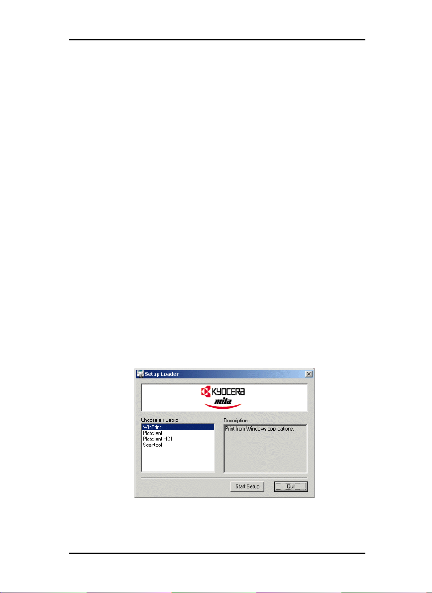
4. The setup program will open the following dialogue “Setup
Loader”:
2
Page 3

INTRODUCTION
5. Choose the program to be installed and click once on the
button “Start Setup”.
6. Follow the instructions given by the setup program.
Start and quit program
• Start program
The installation program sets up its own program group with
program symbols towards the end of the installation. To start
KM-SCANTOOL, open it via the “Start“ bar or double click on its
program symbol.
After the program has been started, the program window, the
job editor and the scanner settings are opened.
• Quit program
You can either quit KM-SCANTOOL via the menu item “File Exit“ or with the usual Windows keyboard shortcut “ALT+F4“.
The program’s functions are now described in the following
chapters.
3
Page 4
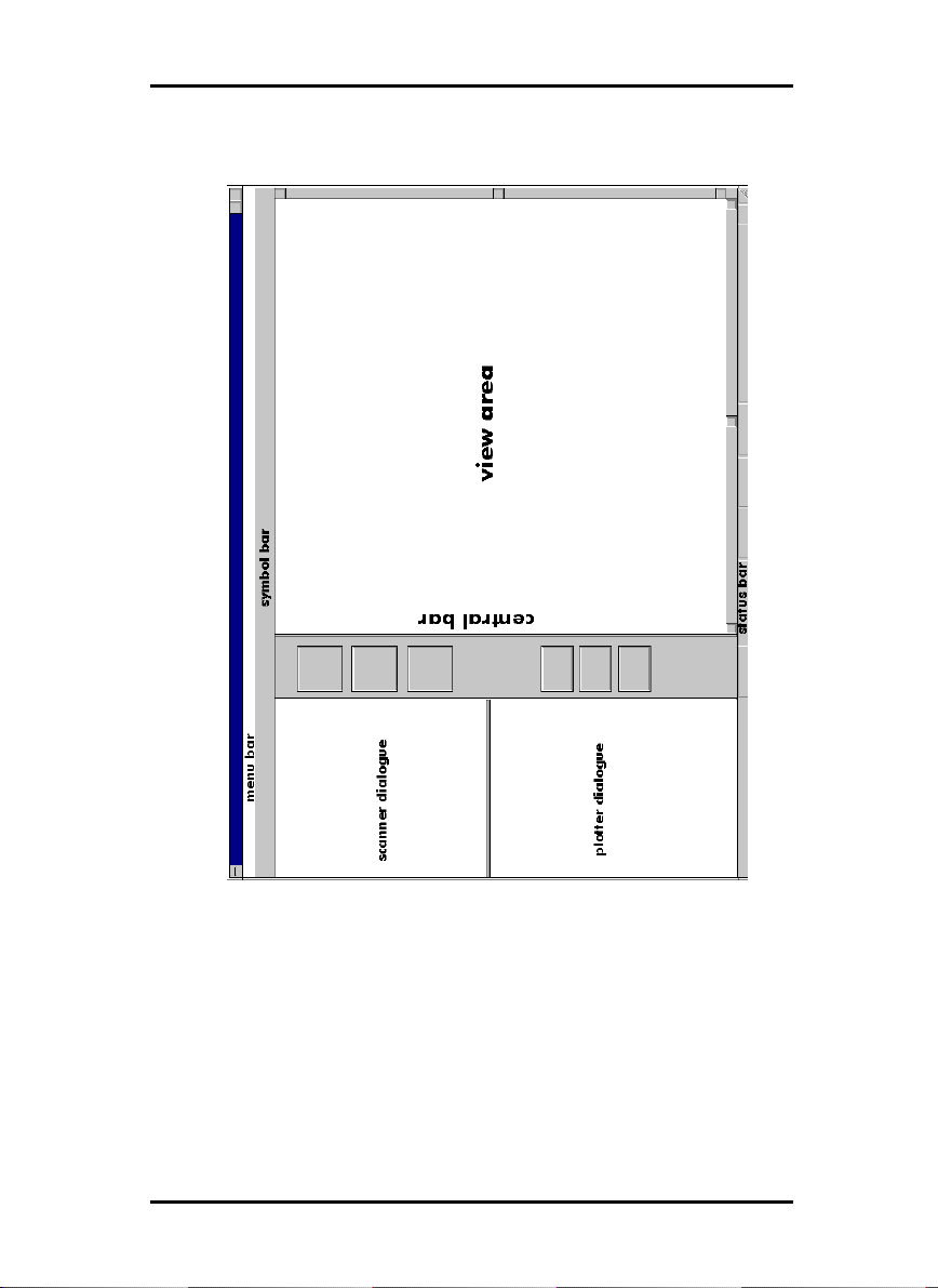
Program Window
PROGRAM WINDOW
4
Page 5
FILE MANAGEMENT
File Management
Loading drawings
Drawings are loaded using “Open File” on the menu. Your
drawings can have the following file formats:
• Calcomp ....................................................... (*.906, *.907)
• CALS [to MIL-STD-1840B] .......................................... (*.cal)
• RLC ............................................................................(*.rlc)
• T6X ........................................................................... (*.t6x)
• TIFF ............................................................................ (*.tif)
[Group 2,3,4; non-compressed; packbits; striped & tiled]
• Windows / OS2 bitmaps ..........................................(*.bmp)
Multipage documents
KM-SCANTOOL allows you to load multipage documents. There
is no limit to the number of pages per document. Multipage
documents can be edited in exactly the same way as single
pages.
File information
Before you can begin with a possible change to the settings, you
can view a summary of all the currently loaded settings.
Click on the white “i” for information display in the “View” toolbar:
For most file formats you can only see the “Misc“ tab. It contains
e.g. the information about the file format, the drawing size and
used pens. If you open a Calcomp drawing, you can read on this
tab information about general settings (“Pen Source”, “Pen
Scale”, “Pattern Style” etc.) which you can change in the job
editor.
The tabs “Drawing” and “Pens” appear only, if you open a Calcomp drawing file. On the tab “drawing” you get the information about the file format, the drawing size, the used colors etc..
5
Page 6

FILE MANAGEMENT
The tab “Pens” informs you of the pen settings. There can also
be two symbols which inform you of the setting status: The red
exclamation marks point out that the pen is used with several
pen sizes and only the last set pen size can be shown. The green
check shows, that a pen is used for the current drawing.
Saving drawings
Once you have made changes to your drawing, you save them
with the menu item “Save File” or with the standard Windows key
combination “CTRL+S“. Remember that the original version of
the file will be irretrivably overwritten.
Note: Remember that, when saving drawings, some
formats can only be read and not saved. The previous
chapter contains all the information you require for
loading and saving drawing formats.
KM-SCANTOOL can save in the following file formats:
• CALS [to MIL-STD-1840B] .......................................... (*.cal)
• CALS [to MIL-STD-28002A]........................................ (*.cal)
• Intergraph ......................................................... (*.cit, *.tg4)
• PCX ...........................................................................(*.pcx)
• RLC ............................................................................(*.rlc)
• T6X ........................................................................... (*.t6x)
• TIFF ............................................................................ (*.tif)
[Group 2,3,4; non-compressed; packbits; striped & tiled]
• Windows / OS2 bitmaps ..........................................(*.bmp)
Loading settings
Before loading a drawing, you have the option of configuring
the way the drawing is presented in KM-SCANTOOL’s file view.
You open the loading settings from the menu option “Settings Load Settings” or by using the key combination Ctrl + R.
6
Page 7
FILE MANAGEMENT
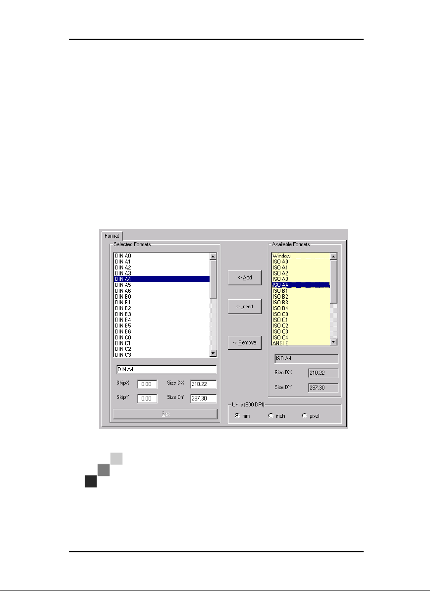
• Formats
Here you can specify whether the drawing is to be loaded into
KM-SCANTOOL’s File View in the original or in a different format. The format list contains all the formats you have preset in
“Settings - Options - Card - Formats”.
If one or more formats are missing, they can be added to the
program, at this point or any time later, using the option “New”.
To add new formats, proceed as follows:
Highlight the format in question in the right-hand list “Available
Formats”, and click on the option “Add”. This will insert the format into the “Available Formats” list. The formats required can
also be transferred directly to the list by double clicking the
mouse:
Note: The “Add” option always adds the selected for-
mats to the end of the list. In contrast, “Insert” will add
a format to the list immediately above the format currently highlighted.
7
Page 8

FILE MANAGEMENT
You repeat this process for each format you wish to use. You can
also enter a format more than once if, for example, you wish to
use a number of drawings with the same format but with different size and margin settings.
“Delete” enables you to remove a format from the “Available
Formats” list.
As soon as a format has been entered in the “Available Formats”
list, it can be edited straight away. To do this, highlight the format in question in the list. You can now change the name, the
format size and the margin settings. To save the setting changes,
click once on “Set”:
− Changing names
Names are changed in the box directly beneath the “Available
Formats” list.
− Changing margins
Margins are changed under “X” (left-hand margin) and “Y”
(top margin).
− Changing format sizes
Format sizes are changed under “DX” (page width) and “DY”
(page height).
− Units
Set the size units to “mm“, “inches“ or “pixels“, which apply for
all settings.
• Width and height
This function enables you, where necessary, also to change the
width and the height. The dimensions are in millimetres.
• Proportional scaling
The value x shown in this box represents the ratio of “width = x
times height”. After activating this value, you can only alter the
figures shown above it for the width. The height will then be
automatically adjusted; in other words the drawing is scaled in
proportion. This facility is useful for example when you know that
a drawing is just a little too large for the size of the paper it is to
be printed on. In this event, you simply activate “Proportional
8
Page 9
FILE MANAGEMENT
Scaling”, and reduce the figure slightly in order to maintain the
correct proportions for the print-out.
• DPI/LPI
In addition, you can also adjust the width and height resolution:
dpi horizontal resolution
lpi vertical resolution
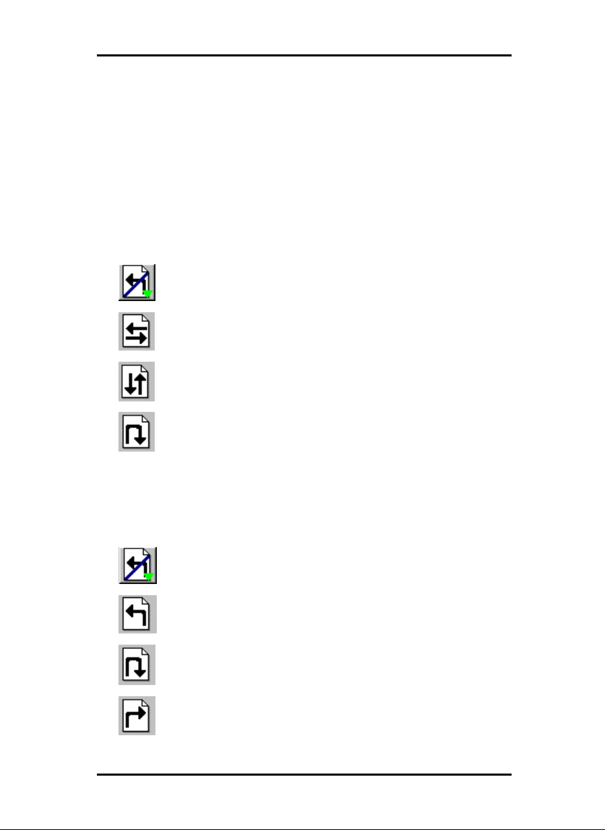
• Mirror
Here you determine whether the drawing is to be shown mirrored or not:
Show drawing not mirrored
Show drawing mirrored horizontally
Show drawing mirrored vertically
Show drawing mirrored around x and y axes
simultaneously
• Rotate
Here you determine whether the drawing is to be shown rotated
or not:
Show drawing not rotated
Rotate drawing through 90° to the left
Rotate drawing through 180°
Rotate drawing through 90° to the right
9
Page 10
FILE MANAGEMENT
Auto rotate - rotate drawing as specified in the
associated vector file
Note: These settings refer primarily to the display in the
view. If you also wish to print the drawing out as shown,
you must select the format setting “Original” in the
plotter dialogue.
10
Page 11

DRIVER MANAGEMENT
Driver Management
Loading the drivers
Reloading the scanner driver will very rarely be necessary. It
could prove necessary for example if the unit has been switched
off, or if a fault has made a shut-down necessary. In order to
inform the program that the equipment is again ready for operation, load the driver using the menu option “Settings - Reload
Scanner”. KM-SCANTOOL will then open the appropriate dialogue box on the left-hand side of the screen.
The same situation could occur with regard to the plotter and
folder drivers, in which case you would need to reload them using the option “Settings - Reload Plotter”.
Configuring the plotter
Sometimes it may be necessary that details of the plotter have to
be entered as described in the relevant Operating Instructions.
For this purpose, open the plotter configuration by clicking once
on the button “Capabilities” below the plotter dialogue on the
left side:
• Maximum Size
Enter the maximum printed width and length that the plotter can
handle. “DX” is the printed width, “DY” the length.
• Trays
List, or subsequently enter, all the output bins that the plotter
makes available. As a rule, this will be a maximum of 4, sometimes even 6 bins.
• Name
Here you can allocate a unique name to each bin: for example
“Bin 1 Paper” or simply “Paper” etc. The name allocated should
conform to the details that you have entered in the control field
of the plotter.
• Width/length
In these two fields, you enter the printed width and length which
can be sent to the current bin.
11
Page 12

DRIVER MANAGEMENT
• Media
In this field you enter the medium with which the current bin is
loaded - paper, vellum, film.
• Type
Here you enter whether the current bin has a roll or a single
sheet feeder.
Allocating SSL paths
As you select “KM-ICP“ as the plotter, you must inform KMSCANTOOL of the spool path in order for it to be able to save
the jobs to the correct directory.
To do this, click on the toolbar button “Options” below the plotter dialogue on the left side.
In the “Options” window, you must first enter the SSL spool path
from the KM-SCANTOOL view, and the path from the KM-ICP
view.
“SSL path as SCANTOOL sees“ means that KM-SCANTOOL
must know where it is to send the SSL jobs.
“SSL path as ICP sees“ means which directory KM-ICP should
regularly look for new print jobs.
As both programs presumably will be running on different computers and connected across a network, the allocated names will
be different for each computer. In this context, the following
should be observed:
Note: We recommend that, when naming the paths,
the UNC (universal naming convention) be employed in
order to ensure a uniform view from all computers.
12
Page 13
ARCHIVE MANAGEMENT
Archive Management
With KM-SCANTOOL it is possible to generate index data for
external archive systems, which it then imports. In order to use
this facility, two basic steps are required in setting it up:
1. In “Options”, the presets for “Archive“ must be entered. To
do this, open the “KM-SCANTOOL Options”. Change to the
“General” card, activate “Archive“ in the “Scan ...“ field and
enter your “Archive Scan Settings“.
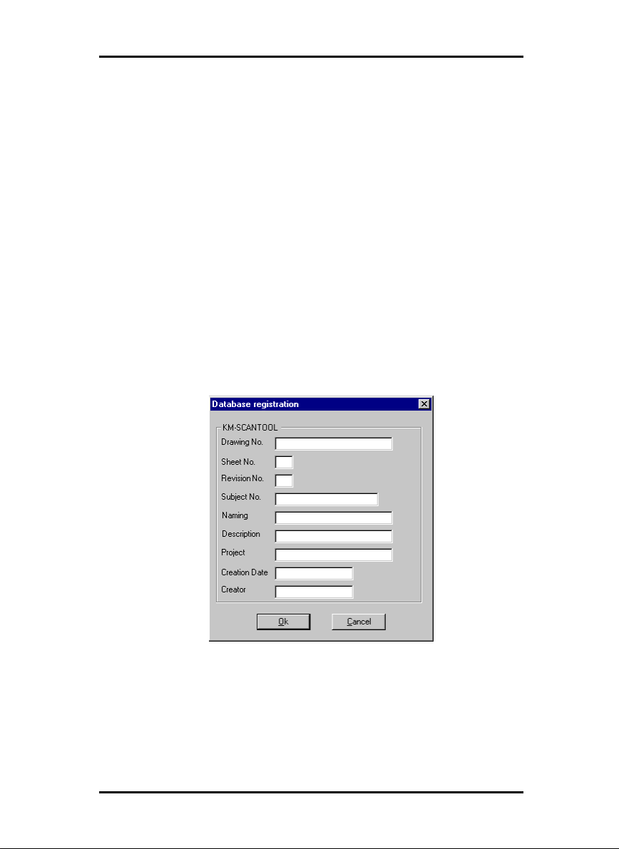
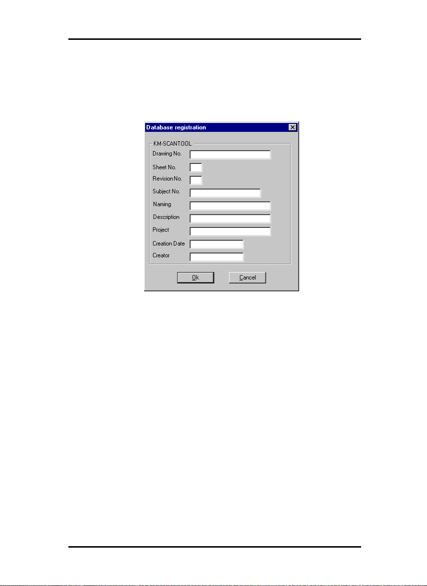
2. All the file data must be entered in the “Database Registra-
tion” screen. It will be noted that an entry does not have to be
made in every box. This will be determined by your field configuration in the DES file.
The “Database Registration” screen has exactly those entry boxes
that you defined with the descriptive database file (*.DES). The
screen could for example look like this:
These entries are separated in the SDF file by a separating character, which you specify, and, in addition, for each drawing are
given a name which is automatically compiled using the current
time.
13
Page 14

ARCHIVE MANAGEMENT
In the following two sections you can see what presets are necessary and how you can set up the boxes for the Database Registration screen.
Specifying presets
If you wish your scanned drawings to be available to an archive,
enable the “Archive“ field before starting scanning.
In addition, KM-SCANTOOL requires the following additional
preset information:
• SDF name and path
After scanning, KM-SCANTOOL creates an archive file ending
with *.sdf, which you can import for example into an archive
management program. The SDF file created can however be
used for any database system. If an SDF file already exists, each
new drawing will add to it until you start a new archive file by
allocating a new name.
Note: KM-SCANTOOL only adds to the archive files.
The importing system is therefore responsible for removing the files.
Allocate a name to the archive file and define the directory in
which the archive files are to be stored. The default directory is
“[LW]:\KyoceraMita\Scantool\Export“.
• DES name and path
Here you enter the descriptive database file which determines
how the entry screen “Database Registration” is to be structured.
All the fields described in the DES file entered will be displayed
on the input screen.
The next step is to inform KM-SCANTOOL which directory to
look in for the DES file. The default directory is
“[LW]:\KyoceraMita\Scantool“, in which the standard DES file
“SCANTOOL.DES“ is located.
14
Page 15
ARCHIVE MANAGEMENT
• Delimiter
Here you enter the character you wish to use to separate the
data records in the SDF file.
Creating descriptive database file
Before you can save data in an archive, a descriptive database
file with the extension *.DES must be set up in the program. You
can either use an existing DES file or create your own file.
Note: The file must always have the name and be
stored in the directory which you have previously entered a DES name and DES path during the setting up
procedure.
DES files are in simple ASCII format. They can therefore be created with a conventional editor.
Rules for File Creation
It is easy to create files. You need only follow these eleven rules:
1. Every valid line begins with a “ = “.
Lines which start with any other character, will be ignored.
2. Comments and comment lines start with a semicolon “;“. All
the characters following a semicolon will thus be ignored.
3. Spaces are always ignored.
4. An archive box and its configuration always comprise so-
called “key words” and their values.
5. Key words must always be enclosed in equals signs (=).
6. An archive box is created with the key word =Name=.
7. An archive file is configured with the key word =TYPE=.
8. With the key word =FLAG= you have the option of deter-
mining the form in which data is entered and displayed in an
archive box.
9. You must define at least one unique primary key word in
each DES file.
10. No distinction is made between upper and lower case letters.
15
Page 16

ARCHIVE MANAGEMENT
11. If a key word is used more than once, the word last entered will
overwrite the value of the existing one.
The following is an example of a valid archive box with its corresponding configuration:
=NAME=operator
=TYPE=string, x20
=FLAG=required, upcase
With this example, you will have generated an archive box in
which the name of the operator is entered, which must not exceed a length of 20 letters. With the flags, you have specified
that the entry of the name is obligatory and that the entry will be
converted to upper case letters.
The following paragraph lists the key words that are available.
Description of the Key Words
There are five key words available to you, namely:
1. =NAME= for creating a new archive box
2. =TYPE= for configuring the archive box
3. =FLAGS= defines the form of an archive box
4. =HEIGHT= defines the height of an archive box
5. =PRIMKEY= provides a search key for working in
the archive
• =NAME=
With this key word, you generate an archive box in which you
enter a name:
=NAME=field name
You can select any name you wish as a “Field Name“. The following criteria must however be met:
1. Do not use accented letters (ä, ü, etc.)
2. Do not use special characters or symbols.
3. For separation use an underscore “_“ and not a space.
4. If possible, do not exceed 16 characters.
16
Page 17

ARCHIVE MANAGEMENT
The acceptable name length is determined by the database
driver. It is recommended however that no more than 16
characters be used.
Once the NAME has been allocated for an archive box, the sequence of the corresponding configuration is immaterial. Allocation of the configuration is completed as soon as a new archive
box is described.
• =TYPE=
For each archive box a field type must be defined. This is
achieved by the key word
=TYPE=string, x255
Six definitions are available: string, date, integer, longint, logical, volume.
→ string:
If the user is to be permitted to enter a string of characters in an
archive box, define the field type as a “string”. Additionally, the
permitted length of the string must be entered, prefixed with an
“x”.
If, for example, you have the archive box with the name “Operator” into which the user may only enter his name with a
maximum of 20 characters, the syntax will be:
=NAME=Operator
=TYPE=string, x20
→ date:
The current date is entered by the program using the syntax
“DATE“. The field type can be extended by the following instructions:
%d
→ day of the month
%m
→ month of the year
%y
→ year
17
Page 18

ARCHIVE MANAGEMENT
Example:
=NAME=date
=TYPE=date,%d.%m.%y
In this example, the archive box will automatically have the date
displayed in the format < day.month.year >.
→ integer:
If you wish the field only to accept whole numbers, allocate the
type “integer“ to the field. When “integer“ is used, only whole
numbers in a limited range may be entered, e.g. from –32768
to +32767. For very lage numbers, the field type “longint“ is
available.
The field type “integer“ contains no supplementary parameters.
Example:
=NAME=sequential number
=TYPE=integer
→ longint:
If you wish to cover a larger range of numbers than is possible
with the field type “integer“, use a “longint“.
The “longint“ field type contains no supplementary parameters.
→ logical:
The field type is a toggle which will accept only two values, e.g.
yes/no, on/off, home/abroad:
=NAME=delivery
=TYPE=logical, home/abroad
If you leave the space after “logical“ blank in the “TYPE“ command, the program automatically enters TRUE or FALSE.
→ volume:
With the field type “volume“, you instruct the program directly to
display the number in the archive box which has been automatically allocated to the record in question.
This field type contains no supplementary parameters.
18
Page 19

ARCHIVE MANAGEMENT
• =FLAGS=
The key word =FLAGS= serves to define the form of input and
display of an archive box. Should you wish to allocate several
flags to one archive box, you need only to add them, one after
the other, separated by commas. It is not necessary to repeat the
initial key word each time.
=NAME=operator
=TYPE=string, x20
=FLAGS=required, leftjust, upcase
There are 10 options open to you:
Required the user must make an entry if the record is
to be saved
LeftJust texts and numerals are justfied left in the ar-
chive box
RightJust texts and numerals are justfied right in the
archive box
Centered texts and numerals are centred in the archive
box
LeftAlign texts and numerals are aligned to the left in
the archive box
RightAlign texts and numerals are aligned to the right in
the archive box
ShowOnly the archive box is only displayed and cannot
be altered by the user
Hidden the archive box is not displayed and remains
hidden from the user in the background
The following four flags can only be used for strings
[=TYPE=string]:
Upcase the user’s text entry is converted to UPPER
CASE letters, and saved
Lowcase the user’s text entry is converted to lower
case letters, and saved
IBMANSI the text is converted from IBM to ANSI char-
acters
ANSIIBM the text is converted from ANSI to IBM char-
acters
19
Page 20

ARCHIVE MANAGEMENT
The conversion from one character set to another is of significance where data records have to be exchanged between different operating systems [e.g. DOS
↔ Windows] where the one
[Windows] text is save in ANSI and the other [DOS] in IBM format.
• =HEIGHT=
To define the height of an archive box, or the number of lines it
contains, use the syntax “=HEIGHT=“:
=NAME=description
=TYPE=string, x200
=HEIGHT=3
The user can enter a description of the drawing in this archive
box extending over three lines but not exceeding 200 characters.
• =PRIMKEY=
Within COPYBASE, the primary key is only of interest in conjunction with the naming of scanned drawings which are to be “prepared” for filing. See also “Settings - Options - Card General Scanner Archive”.
Each descriptive database file [*.DES] must contain at least one
unique primary key. In this context, the term unique means that
all the records in the archive must be clearly unambiguous in at
least one archive box. The simplest example of this would be the
sequential numbering of all records.
In addition, each archive can contain additional search keys
which, however, do not have to be unique.
For the primary key, you need the syntax “=PRIMKEY=“ which
designates an archive box which you have generated with the
key word =NAME=:
=PRIMKEY=drawing number
In this example ARCBASE indicates that the data records are
clearly distinguishable by the number in the “Drawing Number”
box.
The following rule applies for the primary key: The sequence of
the entries after the syntax “=PRIMKEY=“ must move from the
20
Page 21
ARCHIVE MANAGEMENT
“non-unique” to “unique” → from the sub-assembly, through
components, to the component number!
Example of a database description
The above screen would have to be described with the following
DES file:
=NAME=drawing no.
=TYPE=string,x30
=FLAGS=required
=NAME=sheet no.
=TYPE=string,x3
=FLAGS=required
=NAME=revision no.
=TYPE=string,x3
=FLAGS=required
=NAME=subject no.
=TYPE=string,x20
=NAME=naming
=TYPE=string,x30
=NAME=description
=TYPE=string,x200
=NAME=project
21
Page 22

ARCHIVE MANAGEMENT
=TYPE=string,x30
=NAME=creation date
=TYPE=string, x15
=NAME=creator
=TYPE=string,x15
=NAME=volume
=TYPE=volume
=Flags=volume,hidden
=PRIMKEY=drawing no.,page no.,revision no.
Filing Drawings
There are two ways in which a drawing can be filed. Either you
load the drawing and file it manually using the corresponding
option, or you file the drawing shortly after scanning it.
Manually filing drawings
Here, you file a drawing “manually” on the pop-up menu:
1. Open the options with “Settings - Options“ and change to the
card “General”.
2. Allocate the file record a name with the extension *.SDF and
type in the directory in which the record is to be stored.
3. Tell KM-SCANTOOL which descriptive database file (*.DES) is
to be used to structure the entry screen and in which directory
this file is located.
4. Load the required drawing.
5. Open the database entry screen with the option “File - to Archive“ or with “CTRL + A“.
6. Enter your data and save it by clicking on “Save”.
If you wish to archive several drawings, repeat steps 4 to 6.
All the drawings will be written to the same SDF file. If you
wish to create a new SDF file, enter a new name under Options.
Filing drawings after scanning
If you wish to file drawings immediately after scanning them, the
following steps are necessary:
22
Page 23
ARCHIVE MANAGEMENT
1. Before starting scanning, activate the drawings you wish to
file in Options. To do this, open Options with “Settings - Options” and change to the card “General”.
2. Activate the selection “Archive“ in the sector “Scan …”.
3. Allocate the archive file name with the extension *.SDF and
enter the directory in which the file is to be saved.
4. Tell KM-SCANTOOL which descriptive database file (*.DES) is
to be used to structure the entry screen and in which directory
this file is located.
5. Start scanning by placing the drawing in position and clicking
on the scanning toolbar button
6. As soon as the scanning process has been completed and the
drawing appears in the file view, the database entry screen
will automatically be opened so that you can enter your details for filing the drawing you have just scanned.
7. If you scan in further drawings, the database entry screen will
automatically be opened as soon as each individual scan has
been completed.
23
Page 24

Presets
Before starting work, you should complete all those presets
which remain unchanged until you specifically wish to alter them.
The presets are entered in three windows and relate to a number
of features which include the format Calcomp, adaptation of the
print formats and the general settings for scanning and plotting.
Calcomp
The window for the Calcomp presets can be opened with the
option “Settings - Formats - Calcomp”.
In addition to the attributes of the 16 Calcomp pens, this window
is used for setting additional attributes such as pen size and
color factors.
Creating or changing configuration files
If you wish to create a new Calcomp configuration file (*.ccf),
simply start entering the presets and save them in a file. If you
wish to change an existing file, load it with the toolbar button
“Load”.
PRESETS
If you have clients with very specific settings, you can set up individual files here and save them under unique names. This enables you to carry out special client orders rapidly and at any
time.
“Pen” Card
The pen attributes are set on the card “Pen”:
24
Page 25

PRESETS
The settings entered here are applied only if you expressly wish
to employ Calcomp pen attributes that you have defined yourself
and not those from the Calcomp configuration file enclosed. The
procedure for setting pen attributes is simple:
• Pen Size
The size of the pens is entered directly in the first colum under
“Size” from the keyboard. The maximum size will depend upon
the unit of measurement that you specified in the configuration
program. The unit of measurement currently selected is displayed on the status bar at the bottom of the screen.
If you wish to “switch off” a pen, simply enter “0” as the pen size
or set the pen color to “white”.
The standard sizes of the 16 Calcomp pens are listed in the Appendix.
• Pen Color
The pen color is selected in the second column under “Color”.
Click on the arrow on the right of the color box and drag the
mouse to the color you require. If you wish to “switch off” a pen,
simply enter “0” as the pen size or set the pen color to “white”.
You set which grey shade is to correspond to a specific color on
the card “Color”.
• Grey Shades
The grey shades can only be set if you have selected grey as the
color. Here again, changes are made directly from the keyboard.
25
Page 26

• Fill
With “Fill”, the program offers a useful facility to set the pen attributes for all 16 pens simultaneously. To do this, first select the
pen size, the pen color and the grey shade, and then click once
on “Fill”:
When entering the pen size, make sure that you separate the
decimal places with a full stop. The program will ignore the
decimal places if a comma is used!
“Color“ Card
In order to allocate the required grey scale to each individual
color, open the card “Color”:
PRESETS
The percentages are changed directly from the keyboard. Clicking “OK” closes the window and saves your entries. If the data
you have entered is not to be saved, close the window with
“Cancel“ or “ESC“.
In this window you set the grey scale you wish each color to
represent. Use this facility if e.g. you have company-wide standards for each color. If this is not the case and you do not wish
to work through all the colours, you can set all the pens to “grey”
26
Page 27

straight away on the card “Pens” and specify the individual grey
scales per pen there.
“Misc“ Card
• Pen Source
If you activate the “File“ field, you instruct the plotter to use the
pen width information in the entry’s SSL file when plotting and
not the settings from the “Pens“ tab. If no pen widths are defined, the program uses your settings.
If you activate “User“ your settings are always used
PRESETS
• Pen Scale
Activate this field if the pen widths are to be scaled at the same
time as a drawing is scaled. To avoid the possible loss of information when printed ensure that have set at least one minimum
pen width if the drawing is to be reduced in size and at least one
maximum pen width, if the drawing is to be enlarged by scaling.
• Ignore pen widths
Activate this option, e.g. if a drawing is exactly the same size as
a ISO A4 sheet, to guarantee that it is plotted on an A4 sheet
and not on the next larger format because the pen widths were
too large causing the drawing to slightly exceed the A4 format,
thereby causing unnecessary waste paper.
27
Page 28

PRESETS
In this way, you can ensure that a drawing that has exactly the
same size as a standard format is printed on this size paper
thereby avoiding an unnecessary waste of paper.
• Pen Limits (mm)
− Min
Enter the minimum pen widths using the keyboard. The information entered here affects all Calcomp pens.
As there are plotters in which even at the finest resolution the individual pixels are not reliably reproduced, a minimum pen size
is indispensable in these cases. Should one of your settings not
cover the plotter circumstances and no longer guarantee the
printout of a drawing object, KM-SCANTOOL automatically adjusts the pen widths.
− Max
Using the keyboard, enter the maximum pen widths. The entry
affects all Calcomp pens.
Analog to the problem with the minimum pen widths, you can
set the maximum thickness that the pen draws, e.g. to prevent
the drawn objects from overlapping when printed. Setting the
maximum pen widths on the other hand is less seldom necessary. Should one of your settings not cover the plotter circumstances and no longer guarantee the printout of a drawing
object, KM-SCANTOOL automatically adjusts the pen widths.
• Step size/cm
Some time ago, most plotters had stepper motors, which ran at a
varying number of steps per centimeter. In the meantime, the
standard is 800 steps per centimeter. The KM-SCANTOOL
therefore enters 800 as a default value, which does not normally
have to be altered. Nevertheless, it is sometimes advisable to ask
the customer what step number per centimeter they are used to
working with to guarantee plot consistency. Furthermore, it can
be necessary to make a change to reduce the DPI, to release
more system memory for large drawings:
Attention: If you enter a larger value, you will obtain a
s ma l l e r drawing: The entry 1 equates to 0.125 %.
28
Page 29

PRESETS
Example: if you enter 801, the drawing is reduced to
99.875 %.
• Pattern Style
Three types of patterns are defined for Calcomp drawings, in
which the “Pattern“ command is used.
“Round“ means that a certain colored area is filled with a certain
number of filled circles, which are given a certain arrangement
on the area, to achieve an intended color saturation.
In “Random“ on the other hand a percentage of color saturation
is determined for the same colored area, which is then converted
into the necessary number of pixels, which are randomly arranged over the area to achieve the intended color saturation.
Which is why that when circle patterns are overlapped, the covered areas cannot be as clearly identified as if two random patterns are overlapped. The recommended default setting is
therefore “Random“, because you can achieve the best results.
As the “Round“ setting has been installed as a standard to date,
this option has been retained of you do not see the need to print
the same drawings differently in future.
Finally, you can also select the gray value pattern “Symmetric
pattern“. As the name suggests, the “Symmetric pattern“ produces a symmetrical gray value pattern. Try and see which pattern produces the best printing results for your graphic. To do
this you must reload the drawing in preview file after each
change.
• Synchronization
Synchronization is used to check the completeness of the Calcomp files, which have been sent from the application program.
Four pieces of information are used for the synchronization settings:
• Sync character
• End character
• Double Sync
• Test sum
29
Page 30

PRESETS
You can either let KM-SCANTOOL determine the values or you
can enter the necessary settings yourself. If the program is to
determine the values, activate “Auto detection“.
We recommend that you do not alter the standard values if you
want to enter the settings yourself. Should you nevertheless want
to make a change or to find out more on the topic, compare the
settings with those in your CAD system or read the following section in the “Calcomp Inc.“ manual:
“CALCOMP - ONLINE REFERENCE MANUAL“ in the section
“Data Message Format“.
The standard settings are:
Sync character: 2
End character: 0
→ [setting from 0 to 127 possible]
→ [setting from 0 to 31 possible]
Double Sync: OFF
Test sum: OFF
The following two examples serve as possible comparisons:
• AutoCAD12:
Sync character: 22
End character: 13
Double Sync: ON
Test sum: ON
• FordCAD:
Sync character: 2
End character: 3
Double Sync: OFF
Test sum: ON
Options
You open the options window from “Settings - Options” or by
pressing the following button on the toolbar:
30
Page 31

You will find the following cards:
• Format
• General
“Format“ Card
On the “Formats“card you select the format of drawings you require for your work, and change them to suit. All the formats that
you specify here will appear in the selection menu of the scanner
dialogue boxes and plotter dialogue boxes on the left program
side. In addition, you specify the unit of measurement you wish
to employ.
In order to adapt the drawings formats in this way, you must first
inform KM-SCANTOOL of all the formats you will be using. To
do this, mark the format required in the right-hand list “Available
Formats” and click on the button “Add”. The format will then be
inserted into the list “Selected Formats”. The formats required
can also be entered directly into the list by double clicking the
mouse.
PRESETS
Note: The “Add” button always adds the selected for-
mat to the end of the list. In contrast, “Insert” will insert
the selected format one place above the format currently marked.
Proceed in this manner for each format you wish to use. you can
also list a format several times if you wish to use that particular
format for drawings with different sizes and margin settings.
Pressing “Delete” removes the format fom the list of “Selected
Formats”.
A format can be edited as soon as it has been added to the
“Selected Formats” list. To do this, mark the format in question
in the list. You can now change the name, the format and the
margin settings.
31
Page 32

PRESETS
• Changing the name
The name is changed in the box directly beneath the “Selected
Formats” list.
• Changing the margin settings
The margin settings are changed under “X“= left-hand margin
and “Y“= top margin.
• Changing the format size
The format size is changed under “DX“ and “DY“. “DX“ refers to
the width, “DY“ to the height.
• Units
You select the unit of measurement to apply to all the dimensions in KM-SCANTOOL at the bottom right-hand side of the
“Formats“ card. You can choose between “mm“, “inch“ and
“pixel“:
Note: The newly selected unit of measurement will not
apply and be displayed on the status bar at the bottom
of the screen until you have closed the “KMSCANTOOL Options“ window by pressing “OK“.
“[600 DPI]“ indicates that 600 dpi is the default value in KMSCANTOOL and that, when changing the unit of measurement,
all the conversions are always based on 600 dpi.
“General“ Card
On the “General” card, various entries for plotting and scanning
are entered which apply generally to all operations, e.g. specifying the paths on which files are saved and loaded:
32
Page 33

PRESETS
• Specifying plot directories
KM-SCANTOOL uses the entry of the SSL print path for both the
generation path and the spool path. This means that KMSCANTOOL saves all those SSL sets of drawings in this directory
which you have generated manually or which you have automatically had generated during scanning.
Thus KM-SCANTOOL uses the directory during plotting in order
to access the print jobs saved there.
Warning: Drawings and sets of drawings should, as a
general rule, be located in this directory. Should the
program report that no drawings were found, check
that the right path has been entered and that the
drawings are located in the correct print path.
Specifying the CFG directory is also of significance if you have
already worked with the MS-DOS version of “KM-SCANTOOL“.
Furthermore, there is a difference between SSL and CFG mode
in that, although the CFG format is simple, it is unable to print
33
Page 34

PRESETS
out sets of drawings. In contrast, you can print out sets of drawings with the new job description language “SSL”. The SSL syntax
is however more complicated than the CFG syntax.
You change the directory path by clicking on the button to the
right of the entry fields. The program will open a window in
which you can set up the required directory.
• Autostart
Activating the “Autostart“ box is useful when several drawings
are to be scanned and saved as files, one after the other. KMSCANTOOL saves the first drawing and automatically starts a
new scanning operation immediately without any further entries
having to be made. The Autostart function can also be used for
copying. This has the advantage that you can remain at the unit
and feed through and print out all the drawings, without having
to press the button to copy each drawing individually.
• Standard & Set scan settings
Save image rotated:
If you wish to change the format of the files to portrait or landscape before saving, the drawing can be rotated here.
Scan File Type:
Tell KM-SCANTOOL which scan file typ your drawing should
saved as a standard.
• File scan settings
If the scanned drawing is to be saved as a file, the facility is provided for you to abort the scanning and saving process. For this
purpose, the STOP button appears on the control bar during the
process.
The following four entries are required:
Basic name, length and start number:
Enter a basic name for the drawing[s]. These file names are attached to each scanned drawing. If you wish to scan several
drawings at once and save them to file, the start number must be
included in the first part of the file name together with the number of places it comprises. The maximum is four places, which
corresponds to a start number 0001. KM-SCANTOOL always
saves the files as TIFF Group 4 files with the extension “*.tif“:
34
Page 35

PRESETS
SCAN0001.tif
Note: The length of the file name should be acceptable
to the operating system and the network.
In this context, the following must be observed for later scanning
procedures: After each scan, the program retains the settings
until you change them.
Example: If you have given your first scan job for 47 drawings
the basic name “Technology”, the next scanning run of 55
drawings on architecture will be given the same basic name and
numbered sequentially from 48 onwards. This setting should be
changed if you wish to leave the files on the hard drive and later
be able easily to identify each of these two jobs separately.
Specify path:
Finally, the directory in which the files are to be stored, must be
specified. You can change the directory path by clicking on the
button to the right of the entry box. The program will open a
window in which you can enter the required directory. The program default is “[LW]:\KyoceraMita\ScanSave“.
• Archive scan settings
Activate the field “Archive” if you want the drawings that you
have scanned also to be available for an archive.
SDF name and path::::
After scanning, KM-SCANTOOL sets up an archive file with the
file extension *.sdf, which you can save to an archive management system. The SDF file can be used for any database system.
If an SDF file is already there, it will be continually enlarged by
each new drawing until you start a new archive file by entering a
new name.
Enter a name for the archive file and define the directory in
which the archive files are to be stored. The program default is
“[LW]:\KyoceraMita\Scantool\Export“.
35
Page 36

PRESETS
DES name and path:
Here you enter the descriptive database file which is to determine the structure of the entry screen “Database Registration”.
All the boxes described in the specified DES file, will be displayed
on the entry screen.
The next step is to inform KM-SCANTOOL of the directory in
which the DES file is to be found. The program default will show
“[LW]:\KyoceraMita\Scantool“ as the directory in which the standard DES file “SCANTOOL.DES“ is located.
Delimiters:
Here you enter the characters you wish to use to separate the records in the SDF file.
Primary key as file name:
This is a useful option which enables you to locate file names
when scanning with the archive function, because the names
clearly show the subject of the filed drawing, as the name of the
file contains the primary key. The definition of the primary key in
the corresponding database description file [DES file] is such that
the file name is sufficiently informative for a drawing to be instantly recognised. A detailed description of the DES file is given
in the chapter “Archive Management”.
Stamp editor
As the stamp editor is the same one as described in the manual
part of KM-PLOTCLIENT WIN please refer to corresponding
chapter in Client Manual.
36
Page 37

Tools
This section provides a brief overview of the program tools, activated from the toolbars, and information which is displayed on
the status bar. Because of the scope of its function however, the
raster editor has been given a separate chapter.
Toolbar
The toolbar is located directly under the menu bar and provides
access to the following tools:
Open file
Save file
Call up raster editor
TOOLS
Stamp
Call up presets
Open program information
Display bar
Rotate drawing 90° to the left
Rotate drawing 90° to the right
Rotate drawing through 180°
37
Page 38

Drawing in original position
Successively enlarge drawing
Successively reduce drawing
Switch drawing to zoom all
Switch drawing to view 1:1
Multipage document: View first page
Multipage document: Back one page
Multipage document: Enter destination page
Multipage document: Forward one page
Multipage document: View last page
TOOLS
Open file information
Display drawing in black & white view
Display drawing in preview in gray tones
Display drawing in preview lighter,
if gray display – has no effect on printing
Display drawing in preview darker,
if gray display – has no effect on printing
38
Page 39

Central bar
This toolbar is located in the centre of the screen between the
dialogue boxes on the left and the file view on the right. The following functions are available:
→ Start scanning. Please refer to the chapter
“Scanning”.
→ Start copying. Please refer to the chapter
“Copying”.
→ Start plotting a currently loaded file.
Please refer to the chapter “Plotting”.
→ Abort scanning, copying and plotting pro-
cedures.
TOOLS
→ Start the automatic allocation of drawings
to sets of drawings.
→ Manual allocation of drawings to sets of
drawings.
→ Start printing mode for sets of drawings.
39
Page 40

SCANNING
Scanning
This chapter describes scanning, the first of the program’s three
main functions. Here you can see what settings are necessary
and how the actual scanning procedure is started and how it
works.
Setting scanning parameters
Before starting to scan, set the necessary parameters in the
scanner dialogue box, see page 4. For this purpose, the program offers three cards “Specific“, “Settings“ and “Info“.
“Specific“ card
On this card you can enter the three settings: Formats, Resolution and Dither:
• Formats
In this menu, you select the format in which you want the drawing scanned. In addition to the standard facilities “Auto detect”
and “Window”, you will again find the drawing formats which
you preset in the “KM-SCANTOOL Options“.
From the format setting “Auto detect”, the program picks up the
size of the format and thus the direction in which the scanner is
to operate. This is the preset.
40
Page 41

SCANNING
If you wish to select one of your preset formats, the values for the
format size and the format margin will also be taken over. The
portrait and landscape format is freely selectable.
By choosing the format setting “Window”, you can freely set all
the values in the range, the format data being preset from the
window value. The freely adjustable data refer both to the displayed view (portrait or landscape) and to the format size and
margin:
Landscape
Portrait
Offset X Format margin from the left
Offset Y Format margin from the top
Dx Format width
Dy Format height
• Resolution
Here you select the resolution at which the scanner reads the
drawing. The available settings are 150, 200, 300, 400, 600,
800, 1200 and 2400 dpi. A higher resolution will generally produce better results but does involve a larger volume of data and
can thus, under certain circumstances, take longer.
• Dither
As a rule, large scanners generate black and white images although, internally, they always register a drawing in grey shades.
The black and white output displays the different shades of grey
by printing black dots of different sizes and by varying the spacing between them. Viewed from a distance, the image thus appears as a range of grey shades. This process is termed
“dithering”.
If you find this difficult to visualise, try out a number of test runs
in order to gain an impression of the scanning result.
You have a choice of three settings for your “original”:
Line, Loadable Pattern and Floyd Steinberg.
41
Page 42

SCANNING
“Settings“ card
On this card you can enter the five settings: Mirror, Invert,
Gamma, Scan Quality and Server-IP-Address:
• Mirror X
In this section you specify whether the drawing is to be mirrored
horizontally when scanned.
• Invert
In this section you specify whether the drawing is to be inverted
when scanned.
• Gamma
Here you specify the gamma value for the drawing when
scanned.
• Scan Quality
Choose which scan quality should be applied when scanning
your drawing: “standard“ means that your drawing, i.e. scanning data are highly compressed and “high quality“ results in a
lower compression rate.
• Server-IP-Address
Tell KM-SCANTOOL where to find the KM-ICP in your intranet to
be able to send the plot data of your scanned drawing.
42
Page 43

SCANNING
“Info“ card
This card displays all the scanner driver status and error messages.
Starting scanning process
Once all the parameters have been set, the scanner switched on
and the drawing put in place, the scanning process can be
started. To do this, click on the following button on the toolbar:
Aborting scanning process
The scanning process can be aborted at any time by simply
clicking once on the STOP button on the toolbar:
With KM-SCANTOOL, you can also scan and plot whole sets of
drawings at once. This procedure, and the points to be observed,
are described in chapter “Drawing Sets”. The following chapter
deals with the second of the program’s main functions, namely
plotting.
43
Page 44

PLOTTING
Plotting
This chapter describes plotting, the second of the three main
functions. It describes the settings that are necessary, how the
plotting procedure works and how you can use compiled sets of
drawings.
Setting plotting parameters
Before starting to plot, set the plotting parameters in the plotter
dialogue box. For this purpose, the program provides three
cards “Specific“, “Additional“ and “Info“.
“Specific“ card
Six different settings can be made on this card: formats, media
type and position, number of copies, cutting, title block:
• Formats
Here you select the format of the printed drawing. Three options
are available as standard: “Original“, “Percent“ and “Window“.
In addition, you will find all the drawing formats you have selected when setting up the “KM-SCANTOOL Options“.
44
Page 45

PLOTTING
If “Original“ is selected, the plotter will take over the dimensions
of the original drawing. The remaining boxes “Width(mm)“,
“Height(mm)“ and “maintain ratio“ are inactive. The same applies if you select one of your own preset formats.
Selecting the format setting “Window”, enables you to select the
format height and width as you wish:
Width(mm) Format width
Height(mm) Format height
With the third standard option “Percent”, you can reduce the size
of the output drawing to a percentage of the original, within the
range 1.00 to 999.00. This means that the original can be enlarged almost ten times. 100% will reproduce the drawing the
same size as the original.
• Maintain ratio
The value x shown in this box represents the ratio of “width = x
times height”. After activating this value, you can only alter the
figures shown above it for the width. The height will then be
automatically adjusted; in other words the drawing is scaled in
proportion. This facility is useful for example when you know that
a drawing is just a little too large for the size of the paper it is to
be printed on. In this event, you simply activate “Maintain ratio”,
and reduce the figure slightly in order to maintain the correct
proportions for the print-out.
• Media type and position
On this menu, you select the medium on which the drawing is to
be printed - paper, drawing paper, foil or film. The selection will
depend on the type of material you have loaded into your plotter.
With the option “Position“, you symbolically set the position that
your drawing is to occupy on a larger sheet size. For example, if
you are printing out a DIN A4 drawing full size on DIN A1, you
can specify here the position of the drawing on the sheet.
• Copies
Here you enter the number of copies of the drawing to be
printed out. The maximum entry is 999.
45
Page 46

PLOTTING
• Cut Mode
If you want the prints always to be a standard size irrespective of
how much space remains unprinted, select “Format“. The plotter
will then be instructed always to cut the roll to the next largest
size. This can be a drawback where, for example, a drawing that
is only about 0.5 cm larger than a DIN A5 page is printed out
on DIN A4. The result would be that almost 50 % of the page
would be left blank. On the other hand, some folders require
exact formats. “Format“ enables you to meet this requirement.
If you do not select “Format“, the plotter cuts the drawing immediately after the last data. This makes optimum use of the paper
or medium as it results in the least waste.
• Title Block
In order to match the actual drawing header position to that expected by the folder for folding to “Header Up”, the program
offers the following settings:
If the position of the header following folding is irrelevant, activate “Unknown”.
If the position is important however, activate one of the four following options:
Header position unknown, i.e. the drawing fold is
not optimised
Header top left
Header top right
Header bottom right
Header bottom left
46
Page 47

PLOTTING
With this setting, you inform KM-SCANTOOL where the drawing
header is to be positioned. The program will then turn the
drawing into the position required by the folder:
Warning: This setting relates to the original position of
the drawing in the file view. Make sure therefore that
the symbol for the original position is inactivated.
“Additional“ card
This card has four sections in which you can set the options:
mirror, rotate, margin and header:
• Mirror
In this section you specify whether the drawing is to be mirrored
before plotting out. The individual boxes are as follows:
OFF: the drawing will not be mirrored.
X: the drawing will be flipped horizontally.
Y: the drawing will be flipped vertically.
47
Page 48

PLOTTING
XY: the drawing will be flipped through both axes
simultaneously which corresponds to a 180° rotation.
As a rule, you will need this latter setting when the drawing is
scanned in reverse. This is of particular importance when a
drawing is printed out on transparent drawing paper “the wrong
way round”, in order to increase the contrast.
• Rotating
Here you specify whether a drawing is to be rotated before plotting out. Rotation through 0°, 90°, 180° and 270° is possible. On
the setting “Auto“ KM-SCANTOOL automatically rotates the
drawing if this would result in less waste paper.
• Border
If a white border is to be left around the drawing, activate the
box ”ON” and enter the border width. The current unit of measurement is shown on the status bar at the bottom of the screen.
• Output bin
If you select the option “Automatic“, the plotter will pass the
printed copy to the output bin which corresponds to its size.
Should this output bin be empty, the plotter will fall back on the
bin with the next largest size. Details of the output bins can be
obtained from the Operating Instructions supplied with your
plotter unit.
• Invert
Activate this option if the drawing is to be printed in reverse. This
setting is particularly useful when scanning transparencies or
when you have a reversed original drawing which you wish to
restore to the original.
“Info“ card
This card displays all the status and error messages. You can
follow for example the progress of the plotting procedure. This
can be of interest where you are printing out a complete set of
drawings whilst loading new drawings, and wish to see how far
the print job has progressed and whether any problems have
arisen.
48
Page 49

PLOTTING
Should problems arise, or have arisen, on one of these reported
procedures, you are able to stop it using the toolbar button
“Abort”.
Starting plotting procedure
There are three situations in which you will want to initiate a
plotting procedure:
• Scanning, editing, plotting
You have loaded a drawing and, as an option, edited it. It is
ready for plotting out. This is the simplest operation: load the
drawing and print. You start the plotting procedure simply by
clicking on the corresponding button on the toolbar:
• Compile and print a set of drawings
Before starting the plotting procedure, you have either automatically compiled a set of drawings whilst scanning, or have put a
set together yourself, which now awaits plotting. Here, you enable the print mode by clicking on the following button on the
toolbar:
• Copying
This plotting procedure is automatically contained in the copying
procedure. You do not start it yourself with the print mode button. Details of how to copy and which buttons are provided for
this purpose, are given in the chapter “Copying” on page 51.
49
Page 50

PLOTTING
Aborting plotting procedure
As soon as you have started the plotting procedure for a set of
drawings, the button “Print” in the job editor changes to “Stop”.
You can therefore abort a plotting procedure at any time simply
with a click of the mouse on:
50
Page 51

COPYING
Copying
This chapter describes the third of the three main functions in the
program. It shows how a copy can be produced and how the
copying procedure can be aborted.
Starting copying procedure
You have two ways in which to copy a drawing. Either you wish
to reproduce the drawing 1:1 or to enlarge or reduce it.
Copying the drawing retaining original format
The copying procedure comprises three separate operations:
1. Make sure that the format settings in the scanner and plotter
dialogue boxes are correct: in the scanner dialogue box, the
format should show “Auto detect“, and in the plotter dialogue
box “Original“.
2. Click on the “Copy” button on the toolbar:
3. Place the drawing on the scan feed. The drawing will be
copied 1:1.
Copying the drawing to a different format
This copying procedure comprises four separate operations:
1. Set the format to “Auto detect“ in the scanner dialogue box.
2. Beneath it, enter the required size in the plotter dialogue box
under “Format“. As an alternative, you can also set “Percent”
as a format and then enter the required percentage under
“Scale DX”.
3. Click on the button “Copy” on the toolbar:
51
Page 52

4. Place the drawing on the scan feed. The drawing will be
copied to the specified format.
Aborting copying procedure
As soon as you have started a copying procedure, the STOP
button appears on the toolbar:
COPYING
This button enables you to abort the copying procedure at any
time.
52
Page 53

RASTER EDITOR
Raster Editor
The raster editor in KM-SCANTOOL is described in the following
section. Here you can see how to enter your presets and process
the required drawing.
Opening and closing the raster editor
The raster editor is opened either with the option “Editor“ or by
clicking on the corresponding button on the toolbar:
The raster editor is opened and immediately loads the drawing
in the file view of the main program.
You close the raster editor with the option “File - Quit” or by
pressing the key combination “ALT+F4“.
Defining presets
Before starting work with the raster editor, a number of parameters can be preset which will remain applicable - even after
closing the program - until they are expressly changed. The
changes affect the “Insert Mode” and the “Cancel Settings” option.
Defining merge mode
The first preset concerns the manner in which an inserted object
is to be placed on the drawing. You open the window via the
option “Edit – Clipboard Merging”:
53
Page 54

RASTER EDITOR
You have a choice between “opaque”, “transparent“ and “inverting“. You can see the effect of inserting, directly below in the
“Preview” box. If you select “opaque”, the inserted object overwrites the area beneath it. With “transparent“, the inserted object
is placed “beneath” the existing drawing with the result that parts
of the insert may be covered. It is only with the third possibility
“inverting” that both the original drawing and the insert remain
fully visible as the overlapping areas are displayed in reverse.
Undo and multipage settings
With the second preset, you determine how many operations the
program is to register in order for you to be able to cancel them.
You open the window using the option “Options - Common”.
You can choose the option of unlimited undos or enter a maximum number of operations. Any number in excess of this will
depend upon the amount of RAM you have available:
The second option concerns multipage tiff files. Decide as a
standard if all your changes on one page should be valid for all
pages or not.
54
Page 55

RASTER EDITOR
Processing drawings
On the following pages, you can see how a drawing is processed: cutting out, copying, replacing, overwriting specific areas,
and inserting text - and all this in the widest range of sizes and
view arrangements. Furthermore, you can also see how you can
realign a drawing displaced during scanning and how to correct
any clutter or distortion.
The toolbar
Here you see an overview of the whole toolbar together with a
brief explanation. The following sections describe how the individual toolbar buttons are used:
Cut out section
Copy section to buffer
Paste section from buffer
Cut section from drawing and delete remainder
[„Crop“]
Undo last command
Zoom on centre
Zoom on section selected with mouse
Enlarge section in increments
Reduce section in increments
Display whole drawing
Display 1:1
Zoom drawing to full width
55
Page 56

Zoom drawing to full height
Rotate drawing 90° anti-clockwise
Rotate drawing 90° clockwise
Rotate drawing 180°
Flip horizontally
Flip vertically
Insert text
Use pen
Use eraser
Draw lines
RASTER EDITOR
Fill area [ black ]
Delete area [ white ]
Invert large area
Filter drawing
Align drawing
Multipage document: display first page
Multipage document: one page on
Multipage document: one page back
Multipage document: display last page
56
Page 57

RASTER EDITOR
Change drawing to black and white
Change drawing to grey shades
Make drawing darker, if in grey shades
Make drawing lighter, if in grey shades
Restore drawing to original brightness
The mouse
KM-SCANTOOL provides a useful mouse function for your work
in the raster editor. As a rule, all operations are carried out with
the left-hand mouse button. In addition, pressing the right-hand
mouse button opens a window with which you can rapidly call
up and run functions without having to go into the menu or use
the toolbar. You open the window with the right-hand button and
select the operation you require with the left:
Usually, the window will be broken down into two sections, each
listing several operations. The upper section enables you to undo
the most recent operations you carried out. The lower section
lists these operations.
Aligning and filtering drawings
Before actually starting with your work, it may be necessary to
align the drawing first because it has slipped during scanning.
Sometimes you will find that drawings will need cleaning up a
little.
57
Page 58

RASTER EDITOR
• Aligning
It is very easy to straighten a drawing that has slipped during
scanning. Select “Straighten” under the option “Drawing” or the
corresponding button on the toolbar:
You can now pick up the drawing with the mouse at any point
and pull it in the required direction. The program will straighten
the drawing along this “Mouse Line”.
Note: If the drawing is very large and/or very complex
thus needing a great deal of memory to display it,
straightening may take a little time. In this event, the
program will inform you and provide you with the facility to abort the operation.
• Filtering
If the drawing has become cluttered during scanning, this can be
corrected with a filter. Select “Filter” under the option “Drawing”
or the corresponding button on the toolbar:
The program will open a window in which you can define the
area involved and the number of pixels below which the deletion
should take place. If you enter 7 x 7 pixels for example, all the
areas sized 7 x 7 pixels and below will be deleted.
Overlaying drawings
The editor also offers you the facility of “connecting” a vector
drawing with a drawing that has already been loaded.
Assume, for example, that you have a site on the old drawing
which is later to take a stretch of railway line.
In this case, the new drawing need contain only the railway line
itself and can simply be positioned at the required point on the
58
Page 59

RASTER EDITOR
old drawing, using the function “Superimpose drawing” under
the option “Drawing”.
Selecting this option opens a pop-up menu from which you can
select the drawing to be linked to the drawing on the screen.
Vector drawings can only be loaded in Calcomp formats.
Selecting the drawing will “attach” it to the mouse cursor so that
you can position it where you wish. The drawing is inserted as a
transparency. The insert mode cannot be changed.
Cutting, cropping and copying
With the following buttons, starting from the left, you can:
• cut out an area defined with the mouse
• copy an area defined with the mouse into the buffer
• paste the area last copied, from the buffer back into the
drawing
• select an area with the mouse and delete (crop) the remain-
der of the drawing
In order to cut or to copy an area of the drawing, only two steps
are necessary:
1. First click on the button
or .
2. Outline the required area by enclosing it with an adequately
sized box.
KM-SCANTOOL will cut out or copy the outlined area into the
buffer.
Drawings or sections of drawings copied into the buffer are
available to all other windows applications as a bitmap.
In order to paste and position a cut section back into the drawing, proceed as follows:
1. Click on the button
.
KM-SCANTOOL “attaches“ the cut section from the buffer
onto your mouse cursor.
59
Page 60

RASTER EDITOR
2. Position the cursor in the required position on the drawing
and press the left-hand mouse button.
KM-SCANTOOL will paste the cut section at the position indicated.
If you wish to retain only the area outlined with the mouse and
delete the remainder of the drawing, you need only to click once
on the second button - the one with the small scissors - and outline the area on the drawing. As you release the mouse button,
the area outside the outline will be deleted:
This is the basic function provided by “Cropping” when you no
longer wish to use the input window “Format Setting”. You also
have the possibility of freely defining an oblong section to be
cropped. To do this, you either enter freely selected dimensions
or call up an existing or a previously defined format from the list
of “Valid Formats”. Should the format you require not be found
in the list, select “New…”. The program will then open the card
“Formats“, with which you are already familiar in the “KMSCANTOOL Options“ from the “Settings“ menu. Once you have
selected the format, you then decide on the form portrait or
landscape. Then click on “Start“, position the outline box and
complete the operation by clicking on the left-hand mouse button.
Undo and delete buffer
This button enables you to undo the last operation you carried
out.
In the editor presets, you were able to define the maximum
number of operations which the program should remember. If
you wish to delete this KM-SCANTOOL buffer whilst you are
working in order to free up memory, select the option “Edit –
60
Page 61

RASTER EDITOR
Empty undobuffer”. KM-SCANTOOL will then set up its own,
faster buffer. If another application wishes to call up the [KMSCANTOOL] data from the buffer, KM-SCANTOOL transfers the
data into the Windows buffer.
As long as the data are not called up by another application,
they remain in the KM-SCANTOOL buffer. When closing the
raster editor, you will be asked whether the data should remain
accessible to other applications, i.e. whether they should be
transferred to the Windows buffer or not.
The Windows buffer can be deleted via the option “Edit – Empty
clipboard”.
Select view and change position
There are thirteen ways in which you can alter the view size and
position:
From left to right, the buttons have the following functions:
• zoom to centre
• zoom on area outlined with the mouse
• enlarge section in increments
• reduce section in increments
• return to whole view
• change to 1:1 view
• zoom drawing to full width
• zoom drawing to full height
• rotate drawing 90° anti-clockwise
• rotate drawing 90° clockwise
• rotate drawing through 180°
• flip horizontally
• flip vertically
The last five buttons relate to rotating and mirroring. Using them
does change the view or the position of the drawing, but it also
changes the drawing as a whole. When closing the drawing, the
61
Page 62

RASTER EDITOR
program will therefore first ask you whether you wish to save the
drawing or not.
Using the buttons is simple. Apart from the two magnifying
glasses, you need only click on the button in question once and
the operation will be carried out immediately.
: If you want to zoom in on a point centred around the current cursor position, click once on the first magnifying glass from
the left, and then on the required position on the drawing. The
program will then enlarge the drawing by one step, centering it
on the position indicated by the cursor.
: In order to zoom in on a defined section, click once on the
second magnifying glass from the left and then draw an adequately sized box round the section of the drawing required. The
program will enlarge the defined section by one increment. You
can then enlarge the section in increments as often as you wish
without having to click on the magnifying glass again.
Inserting text
If you wish to insert text, the entry window can either be opened
with the option “Tools - Enter Text” or by clicking once on the
corresponding button:
The window for inserting and formating text, straightening and
specifying the merge mode will then open:
62
Page 63

RASTER EDITOR
• Text insertion
You enter your text in the box top left. The length of the text will
depend upon the size of the font you have selected. Only one
line of text can be entered; the program does not wordwrap.
You can see the font size currently selected directly below the
entry box on the right of the button “Font”.
• Alignment
If you do not wish the text to be positioned as standard, it can be
rotated clockwise through 90°, 180° or 270°.
• Font
If you wish to alter text attributes, click on the button “Font” beneath the text entry box. In this window you can alter all the font
settings just as with the Windows program with which you are
familiar: font, style, size and effects.
Note: The color if permanently set to “black” and can-
not be altered.
• Merge mode
Open the window with the button “Merge”. Here you have a
choice between “opaque”, “transparent“ and “inverting“. You
can see the effect inserting has directly below in the “Preview”
box. If you select “opaque”, the inserted text overwrites the area
beneath it. With “transparent“, the inserted text is placed “beneath” the existing drawing with the result that parts of the insert
may be covered. It is only with the third possibility “inverting”
that both the original drawing and the text insert remain fully
visible as the overlapping areas are displayed in reverse.
Note: Changing the entry mode using the text entry
window does not change your preset. Both settings are
independent of one another. The setting made here
applies only to the insertion of the text.
63
Page 64

RASTER EDITOR
Using pen and eraser
In addition to the text tool, there are six further facilities for
making changes to the drawing:
The use of the buttons is simple. Click once on the required button and set the pen or eraser thickness in the entry window. You
can now apply the tool with the preselected thickness.
Drawing lines
If you wish to draw lines, you can open the entry window either
with the option “Tools - Line”, or by clicking once on the corresponding button:
Set the line thickness in pixels in inches or centimetres in the entry window. You can then draw directly with the mouse without
having to close the window. This has the advantage that you can
draw several lines of different thickness without having to go
back to the menu each time. The unit of measurement currently
applied is displayed on the status bar.
Filling, deleting and inverting areas
You have three tools with which you can work on large areas:
From left to right, these buttons have the following functions:
• fill area [ black ]
• delete area [ white ]
• invert area
64
Page 65

RASTER EDITOR
The application of these operations is in all three cases the
same. Activate the tool required and outline the area in question
with the mouse. The operation will be carried out immediately.
Multipage documents
When printing multipage documents it should be noted that all
the pages of the same size and that not all the pages can be
printed out at once. There is no “from … to” facility for page
numbers.
The following buttons enable you to move around in multipage
documents:
Jump to the first page of the document
Jump back one page
Jump forward one page
Jump to the last page of the document
Enter a specific page
This last button opens a dialogue in which you can directly enter
the number of the page to which you want to jump. KMSCANTOOL automatically recognizes the maximum acceptable
page number.
Grey shades or black and white
There are two possibilities of displaying a drawing, in black and
white or in grey shades. Five tools are provided for this purpose:
From left to right, these buttons have the following functions:
• display the drawing in black and white
• display the drawing in grey shades
65
Page 66

RASTER EDITOR
• make drawing darker (in grey shades only)
• make drawing lighter (in grey shades only)
• restore original brightness
The use of the buttons is very simple: you need only to click on
the required button once and the operation will be carried out
immediately.
66
Page 67

DRAWING SETS
Drawing Sets
KM-SCANTOOL offers you the possibility of scanning and plotting whole sets of drawings in one operation. You can scan as
many drawings as you wish, one after the other, have them
automatically entered in the job editor list and defined as a plot
job. In addition to the automatically compiled job list, you can
also put together a set of drawings yourself. This chapter describes how sets of drawings can be compiled.
Whether a drawing is allocated to a particular drawing set
manually or automatically, most of the operations are identical.
Nevertheless, in the interest of clarity, these steps are described
in both sections.
The following text deals with automatic allocation. If you wish to
allocate a drawing manually, skip to page 70.
Automatically compiling drawing sets
1. Click on the following button on the toolbar:
2. A window is opened in which you can give the set of draw-
ings a name:
The name can be up to 250 letters in length and will automatically have the extension “*.ssl“ added to it. In order to
67
Page 68

DRAWING SETS
call up an existing set of drawings so as to change or add to
it, go into the corresponding sub-directory using the “Browse”
command. Click on “OK” to confirm the selection.
3. Next, the job editor will be opened:
4. Place the drawing in the scanner feed.
5. Click on the scan button on the toolbar to start the scanning
operation:
The drawing will be scanned and automatically added to the
list of sets of drawings.
Note: The drawings adopts the KM-SCANTOOL set-
tings as presets and not the presets on the job editor
cards “Default Specific” and “Default Additional”.
68
Page 69

DRAWING SETS
→ If you have activated the options “File” with “Autostart”
under “Scan...“ in the window “KM-SCANTOOL Options“,
you can now scan as many drawings as you wish one after
the other without having to click on the button for each
drawing.
→ If you have activated the options “Archive” under “Scan...“
in the window “KM-SCANTOOL Options“, the archive settings window will now be opened.
6. Once you have scanned all the drawings you wish to include
in the set or in the job, close the job editor by clicking on the
following button on the toolbar:
Incidentally, it is the same button that you clicked at the start
described in paragraph 1. You will notice however that the
arrows have changed direction.
7. Now, the window for saving your settings will be opened:
If you wish to retain your settings, click on “Save Set”. If you
wish to quit the operation, click on “Cancel creation”. If you
wish to continue working on the set of drawings, click on
“Cancel”.
69
Page 70

DRAWING SETS
Manually compiling drawing sets
1. Click on the following button on the toolbar:
2. A window will open in which you can allocate a name to the
set of drawings:
The name can be up to 250 letters in length and will automatically have the extension “*.ssl“ added to it. In order to
call up an existing set of drawings so as to change or add to
it, go into the corresponding sub-directory using the “Browse”
command. Click on “OK” to confirm the selection.
3. Next, the job editor will be opened:
70
Page 71

DRAWING SETS
4. Load the drawing with the option “File - Open” or with the
following button on the toolbar:
You can now alter the drawing and then save it.
5. Allocate the drawing to a drawing set by clicking on the fol-
lowing button on the toolbar:
Note: The drawing will take over the KM-SCANTOOL
settings as presets and not those on the “Default Specific” and “Default Additional” cards of the job editor. If
you wish to add drawings via the job editor however,
the settings on the job editor preset cards will apply.
Repeat steps 4 and 5 if you wish to allocate several drawings
to the set.
6. Once you have allocated all the drawings, close the job edi-
tor:
Incidentally, it is the same button which you clicked at the
start described in paragraph 1. You will notice however that
the arrows have changed direction.
7. Now, the window for saving your settings will be opened:
71
Page 72

DRAWING SETS
If you wish to retain your settings, click on “Save Set”. If you
wish to quit the operation, click on “Cancel creation”. If you
wish to continue working on the set of drawings, click on
“Cancel”.
Printing a set of drawings
You can either print out your set of drawings immediately it has
been compiled, or at a later time.
The plot procedure
The following steps are required for printing out a set of drawings or a job:
1. Click on the button “Plot Mode” on the toolbar:
The “Plot Mode” window will be opened. The buttons in this
window are explained in detail on the next page.
2. Select the set of drawings you wish to print.
3. If you wish to make changes in that set, activate the option
“Contents” under “Set options”. KM-SCANTOOL will now
open the job editor thereby giving you a further opportunity
to make any changes before the final print. If you do wish to
make changes, the chapter on Job Editor on page 76 provides details.
If you wish to make no more changes, proceed with next step
4.
4. Click on the button “Plot”.
72
Page 73

DRAWING SETS
5. When the print operation has ended, close the window
“Plotmode” with “Close”.
6. Whilst the plotter is printing out the set of drawings, the but-
ton “Plot“ changes to “Abort“, thereby giving you the opportunity of ending the print operation prematurely.
The plot mode settings
• Refresh
Clicking on this option enables you to refresh the display in both
“Plotmode” windows by reading the spool directories in again.
This will occur automatically at the end of the print run provided
that you have enabled “auto” as the print mode.
• Direct plot
If you wish to print only a single drawing, this option opens a file
selection window in which you can open the required file.
73
Page 74

DRAWING SETS
• Plot
Clicking on this option starts the print operation for the set of
drawings. Depending on whether you have selected manual or
auto as the “Plotmode”, either only the selected drawing set
[manual] or all the sets in the list [auto] will be printed.
• Start index
This feature enables you instruct KM-SCANTOOL to print drawings from a particular number onwards within the set. Example:
you have a set comprising ten drawings and wish only to print
out the last four. To do this, you enter “7” at this point. This facility is also useful when you know for example that a particular
drawing is aborting the printing procedure. In this case, you can
avoid printing the drawing in question by beginning with the
drawing immediately following it in the job editor list.
• Copy index
This feature enables you instruct KM-SCANTOOL to print drawing sets from a particular copy onwards. Example: You have
created several sets and already printed out the sets 1 to 4. If
you like to start with the following set, you enter “5” at this point.
So the difference between start index and copy index is, that
“start index” applies to the single entries of one set and “copy
index” applies to complete sets.
• Delete after plot
The files are deleted once they have been plotted out. There is a
circumstance however in which you may wish to make an exception to this standard procedure. Should you have included a
drawing in the drawing set which is in any other directory of your
choice but not in the spool directory, KM-SCANTOOL will make
a copy of the original and save it to the spool directory. When,
after plotting, all the files in the set of drawings in the spool directory are to be deleted, this copy will also be deleted but the
original will be retained. You could use this facility where an important drawing is to be printed out with the set, but is not to be
deleted together with all the other files.
• Contents
If you wish to check which drawings are in the set and possibly
make changes to the list, activate this option. KM-SCANTOOL
74
Page 75

DRAWING SETS
will then open the job editor with the list of all the drawings, on
the left-hand side.
• Saving and deleting the set
“Save Set” is only active if you have previously made changes
with the job editor. The job editor can be opened by clicking on
“Contents”.
• Sort
If you wish to sort the print out according to the creation date of
your sets, choose option “Time”. With activated sort “ABC“ the
print outs are in the sequence A, B, C - A, B, C - A, B, C. If the
printout is not sorted, the complete number of entries are printed
out: A, A, A - B, B, B - C, C, C.
75
Page 76

JOB EDITOR
Job Editor
This chapter describes all the settings available for whole jobs
and individual drawing entries. The individual settings range
from the format size, through stamp, pen settings and the output
bin, to defining the position of the drawing header.
The job editor opens when you start changing a set of drawings
or a job. Both of these operations are started by clicking a
mouse on the following toolbar button:
Job editor description
As the job editor is the same one as described in the manual
part of KM-PLOTCLIENT WIN please refer to the corresponding
chapter in Client Manual.
Adding and deleting entries
Three options are provided for adding new entries to the job
editor. You either use the KM-SCANTOOL toolbar button, the
pop-up menu opened with the right-hand mouse button, or by
dragging and dropping.
Adding by toolbar button
In order to add an entry or a drawing using the toolbar button,
only three steps are necessary. The configuration values which
you have set in the plotter dialogue box on the left-hand side of
the program are attached to the drawing:
1. Load the drawing to be added to the set by clicking the op-
tion “File - Open” or the corresponding toolbar button:
76
Page 77

JOB EDITOR
2. Open the drawing set to which the drawing is to be added by
pressing the corresponding toolbar button:
KM-SCANTOOL opens the job editor displaying on the left a
list of all the existing entries.
3. In order to add the currently loaded drawing to the entry list,
click once on the following toolbar button:
KM-SCANTOOL adds the drawing currently loaded to the set
of drawings.
Adding by using the right-hand mouse button
The configuration values which you have set in the plotter dialogue box on the left-hand side of the program are attached to
the drawing. You add an entry or a drawing, using the righthand mouse button, as follows:
1. Open the drawing set to which the drawing is to be added by
pressing the corresponding toolbar button:
KM-SCANTOOL opens the job editor displaying on the left a
list of all the existing entries.
2. Click once with the right-hand mouse button and select the
command “Add” with the left-hand mouse button to add the
drawing to the end of the list, or “Insert” in order to insert the
drawing above a drawing marked in the list:
77
Page 78

JOB EDITOR
3. Select the drawing to be added using the usual file menu.
Adding by drag & drop
Note: In contrast to the above two methods, entries or
drawings which you add by dragging and dropping,
are given the presets which you defined on the cards
“Default Specific” and “Default Additional”.
The following steps are required:
1. Open the File Manager and arrange the two windows from
KM-SCANTOOL and from the File Manager so that they are
either side by side or one above the other.
2. Mark the entry in the KM-SCANTOOL entry list below which
the new entry is to be made.
If you wish to insert a new entry above an existing entry, mark
the entry in the list above the existing one!
If you fail to mark an entry, all new entries will always simply
be placed at the end of the list.
3. In the File Manager, change to to the directory from which
you wish to pick up the new entry.
4. Click on the file using the left-hand mouse button and, hold-
ing the mouse button down, draw the file across to the KMSCANTOOL entry list. Release the button. You can also add
several drawings at once by marking them just as you do for
moving files in the File Manager.
Deleting entries
1. Mark the entry in the KM-SCANTOOL entry list which should
be deleted.
78
Page 79

JOB EDITOR
2. Click once with the right-hand mouse button and select the
command “Delete” with the left-hand mouse button to delete
the drawing from of the entry list.
Closing the job editor
When you want to close the job editor or stop compiling a set of
drawings, click once on the following toolbar:
The program will open a window in which you can either quit
compiling drawing sets or save them:
KM-SCANTOOL ends the drawing set compilation procedure
and closes the job editor.
If you wish to continue working on a set of drawings, click on
“Cancel”. If you wish to finish the whole drawing compilation
procedure, click on “Cancel creation”.
79
 Loading...