

Page 1

Chapter 3
Hardware notes
Page 2

Chapter 3 Contents
3-1 Hardware notes ................................................................................................................................ 4-3
3-1-1 Hardware configuration................................................................................................................... 4-3
3-1-2 Feeder board .................................................................................................................................. 4-4
(1) Feed motor drive circuit ................................................................................................................. 4-4
(2) Pickup solenoid drive circuit .......................................................................................................... 4-6
(3) Parallel/serial converter circuit....................................................................................................... 4-7
3-1-2 Interface connector ......................................................................................................................... 4-8
PF-80/PF-81
3-2
Page 3
3-1 Hardware notes
3-1-1 Hardware configuration
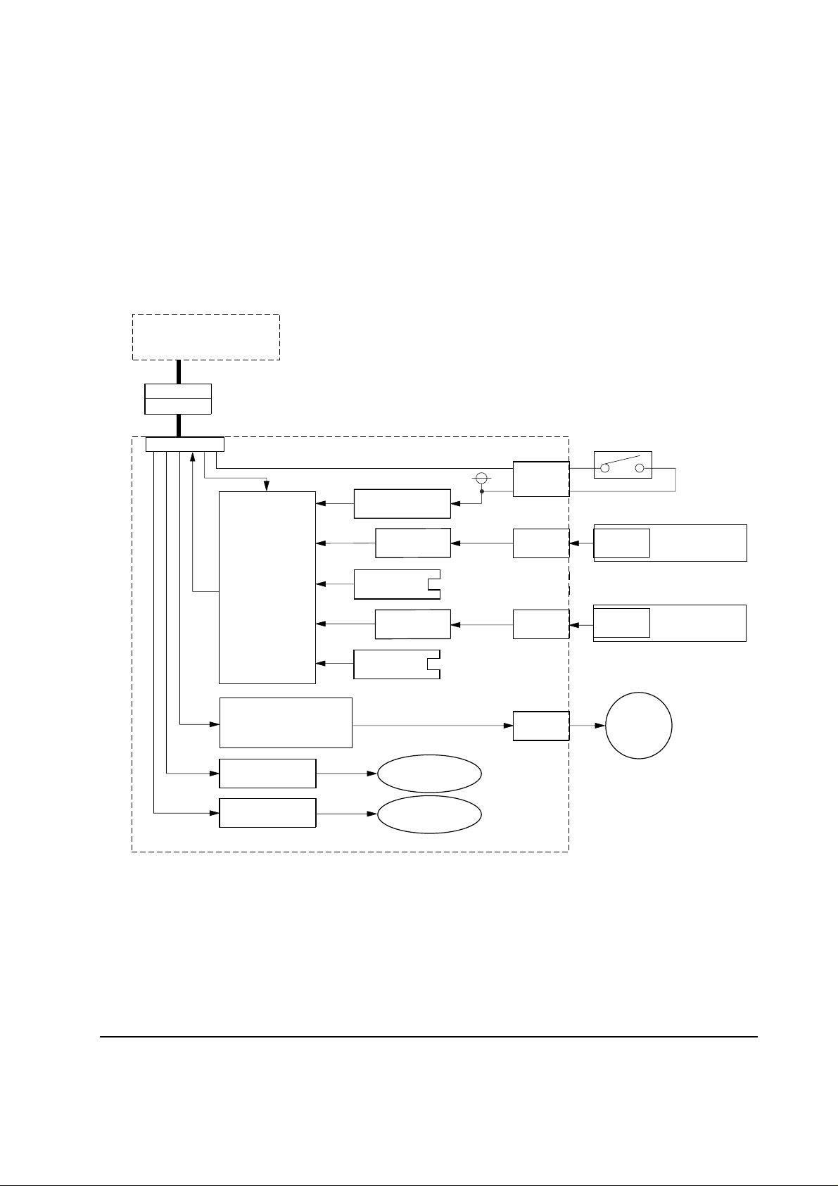
The hardware of the paper feeder PF-80/PF-81 includes the feeder board, tray sensor boards, feed
motor and the door switch. The feeder board is mounted the pickup solenoids, sensors. The feeder
board is under control of the printer main unit. See figure below.
Printer engine
DRAWER
DRAWER
Feeder board
CN901
Door switch
Parallel/serial
converter
circuit
Feed motor drive circuit
Pickup solenoid
drive circuit (A)
Pickup solenoid
drive circuit (B)
Door open
detect circuit
Tray sensor
circuit (A)
Paper empty
sensor (A)
Tray sensor
circuit (B)
Paper empty
sensor (B)
Pickup solenoid
(SOL901)
Pickup solenoid
(SOL902)
+24 V AS
CN902
CN904
CN905
CN906CN903
CN907
Feed motor
Tray sensor
board (A)
Tray sensor
board (B)
Figure 3-1-1 Hardware configuration block diagram
3-3
PF-80/PF-81
Page 4

3-1-2 Feeder board
The feeder board includes the feed motor drive circuit, pickup solenoid drive circuit, and the parallel/
serial converter circuit. The feed motor drive and pickup solenoid circuits drive the feed motor and
the pickup solenoid (SOL901, SOL902), respectively, depending on the control signals given by
the printer. The parallel/serial converter circuit converts the signals detected on the tray sensor
boards, paper empty sensors, and the door switch into the serial data signals which are delivered to
and commanded by the printer.
(1) Feed motor drive circuit
The feed motor (2-phase stepping motor) is driven by the stepping motor driver IC911. When the
OPMCTL signal is low, the current flows into the feed motor. When the signals are output as shown
below, the feed motor rotates.
OPMCTL
A
B
A
B
Figure 3-1-2 Feed motor timing chart
PF-80/PF-81
3-4
Page 5

PF-80
(Motor speed control signal)
PFMSET1
CN901
OPMCTL
Base clock (547 kHz)
Frequency divider
PFMSET1: H (534 Hz)
PFMSET1: L (267 Hz)
Phase control circuit
PF-81
PFMSET1
CN901
OPMCTL
(Clock signal)
617165
ABB
A
Stepping motor
driver
(IC911)
Phase control circuit
OUTBN
OUTB
OUTAN
OUTA
+24 V AS
11
18
1
8
Feed motor
CN905
OUTBN
OUTB
OUTAN
OUTA
+24 V AS
11
18
1
8
CN905
617165
ABBA
Stepping motor
driver
(IC911)
Figure 3-1-3 Feed motor drive circuit block diagram
3-5
Feed motor
PF-80/PF-81
Page 6

(2) Pickup solenoid drive circuit
The pickup solenoids (SOL901 and SO902) are driven by the transistors (Q901 and Q902) respectively. When the O1PCTL signal is high (Q901 turns on), the current flows into pickup solenoid
(SOL901) and the paper is fed from the middle tray . When the O2PCTL signal is high (Q902 turns
on), the current flows into pickup solenoid (SOL902) and the paper is fed from the lower tray.
OPMCTL
O1PCTL
or O2PCTL
Less than 5 s
Figure 3-1-4 Pickup solenoid drive signal timing chart
Pickup
solenoid
SOL901
Pickup
solenoid
SOL902
O1PCTL
O2PCTL
CN901
+24 V AS
Q901
+24 V AS
Q902
Figure 3-1-5 Pickup solenoid drive circuit block diagram
PF-80/PF-81
3-6
Page 7

(3) Parallel/serial converter circuit
The parallel/serial converter circuit is under control of signals OPSCLK and OPSLD. These signals
are used to convert the parallel input signals generated by the paper empty sensors and the door
switch into the serial data signal of OPRDD0 and OPRDD1 which are in turn delivered to the
printer.
+24 V
OPSCLK
OPSLD
CN901
OPSRDD0 (Serial data signal)
OPSRDD1 (Serial data signal)
Figure 3-1-6 Parallel/serial converter circuit
Parallel/serial
converter
circuit
(IC904)
(IC905)
GND
+5 V
GND
D901
5.5 V
GND
Paper
empty
switches
+24 V
CN902
Tray sensor boards
CN903/904
Door switch
3-7
PF-80/PF-81
Page 8

3-1-2 Interface connector
The interface connector is for connection of signals between the paper feeder and the printer. The
diagram below shows the arrangement of the connector pins.
7 8 9 10 11 12
1 2 3 4 5 6
Figure 3-1-7 Interface connector
Table 3-1-1 Interface connector pin assignment
Pin No. Input/Output Signal Function
10
1
2
3
4
Input
Input
Input
+5 V
GND
OPMCTL
O1PCTL
5 V DC power supply
Ground for 5 V DC
Feed motor drive signal L: On (Run), H: Off (Stop)
Pickup solenoid (SOL901) drive signal
H: On (Run), L: Off (Stop)
5
Input
O2PCTL
Pickup solenoid (SOL902) drive signal
H: On (Run), L: Off (Stop)
6
Output
OPSRDD0
Serial data signal (Middle tray status, paper empty
and paper feeder’s door open)
7
8
9
Output
Input
Input
Input
OPSRDD1
OPSCLK
OPSLD
+24 V
Serial data signal (Lower tray status, paper empty)
Clock signal for serial communication
Serial data loading signal
24 V DC power supply
11
12
PF-80/PF-81
Input
GND
Ground for 24 V DC
Feed motor speed control signal (PF-80)
L: High speed, H: Low speed
Feed motor drive clock signal (PF-81)
3-8
 Loading...