

Page 1
Chapter 3 HARDWARE NOTES
Page 2

Hardware Notes
Introduction
3.1 Introduction
This chapter describes an operational overview of the paper feeder. It ensures correct understanding of the behavior of both the mechanical and electrical mechanism of the paper feeder to
assist servicing.
The following basic functions of the paper feeder are discussed in the following pages.
❐ Friction-retarded roller (FRR) system
❐ Electrical parts, page 3-6
❐ IC details and pin assignments, page 3-9
❐ Feed motor driver, SLA7024M (U4), page 3-10
❐ Tray motor driver, TA8428K (U5), page 3-11
, page 3-5
3-2
PF-7E
Page 3
Hardware Notes
Overall block
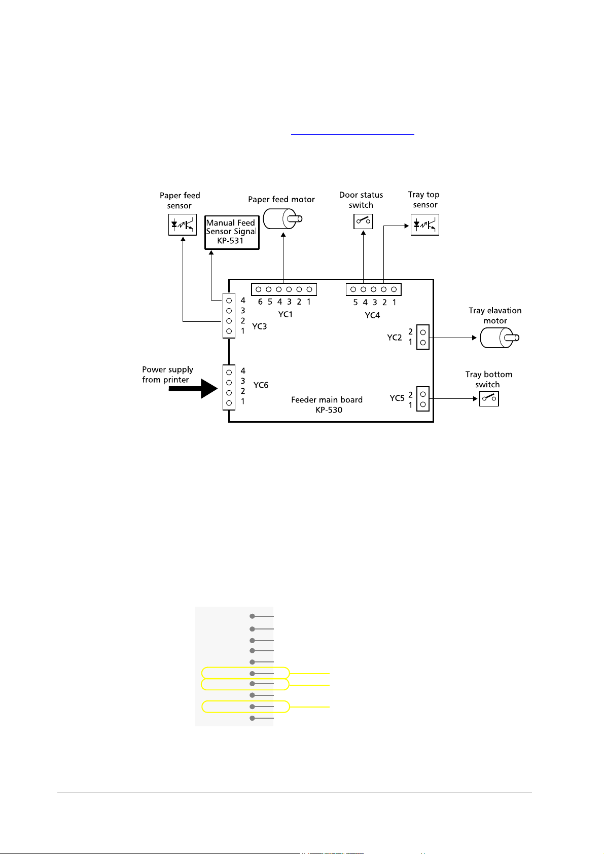
3.2 Overall block
Figure 3.1 Feeder main board
The diagram below shows the main board and the components of the paper feeder. For a fully
detailed schematic information, see Chapter 5 Schematic diagram
.
The KP-531 board provides liaison for the manual feed sensor signal as well as giving an identifying signal that the PF-7E is installed with the printer.
The printer recognizes installation of the PF-7E when pin #6 of YC782 on KP-502 [Envelope
feeder mount board] on the printer (=YC1 on KP-531 on the PF-7E) turns to L. This signal
turns to H in case an envelope feeder EF-1 is installed.
Refer to the connector pin assignment for YC-1 below. Pin #6 is grounded for the PF-7, which
left open for the EF-1, effectively allowing the printer to identify either of these option feeders.
Figure 3.2 YC-1 connector on KP-531
OP
VDD
MON*
UNIT*
OP
PF7UNIT*
PEMP*
SGND
HANDS
PGND
10
1
2
3
4
5
6
7
8
9
Identifies the PF-7 installation
Unused for the PF-7
Manual feed sensor for printer
PF-7E
3-3
Page 4
Hardware Notes
Overview of feeder operation
3.3 Overview of feeder operation
The PF-7E feeds paper which turns on the PF-7E’s feed sensor. If the printer’s feed sensor will
not turn on in 2 seconds since the PF-7E’s feed sensor has turned on, the PF-7E forces paper
into the printer. Unlikewise, the precedent PF-7 feeder pauses when its feed sensor has turned
on until the printer’s feed sensor turns on.
To avoid paper jam caused when several sheets of paper are fed at one time, the feeder uses the
friction-retarded roller (FRR) system for paper feed. The operating theory for this system follows this section.
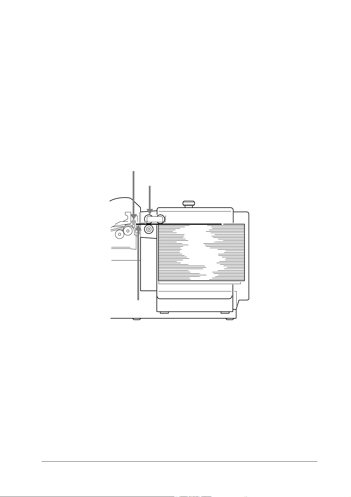
Figure 3.3 Feeder interface to printer
Printer manual feed roller
Feed roller (See page 3-5.)
Subsequently-fed paper
3-4
PF-7E
Page 5

Hardware Notes
Overview of feeder operation
Friction-retarded roller (FRR) system
The paper feeder utilizes the friction-retarded rollers to ensure a reliable paper feeding free of
multiple feeding problem. This system is comprised of the paper feed roller, reverse roller, and
the torque limiter as shown in figure below.
Figure 3.4 FRR system
Feed roller
Reverse roller
Figure 3.5 Feed and reverse rollers
Oneway clutch
In this system, both the paper feed and
reverse rollers are driven clockwise at the
shaft. The reverse roller, however, has the
torque limiter (one-way clutch) at one end
which in normal paper feeding effectively
frees the reverse roller from the shaft to turn
in counterclockwise direction by means of the
friction given by the paper feed roller through
the paper.
Assuming more than one sheet of paper are
accidentally fed and pinched between these
rollers, there no longer is friction between the
rollers as the friction is subtle among the
sheets of paper. The reverse roller can then
rotate following the shaft rotation defeating
the torque limiter. The feed roller continues
feeding the top sheet towards the printer; the
reverse roller feeds the second sheet backward, thus avoiding misfeeding problem.
PF-7E
3-5
Page 6

Hardware Notes
Overview of feeder operation
Electrical parts
The feeder’s internal electronics, including the one-chip microprocessor µPD78213 is used as
CPU, serves mainly for activating and deactivating the motors to elevate the tray and feed
paper (towards the printer manual feed rollers) in cooperation with the sensors.
The function of each major component of the feeder is as follows. (All these components are
connected to the main circuit board KP-369.)
Figure 3.6 Electrical part layout
➊
Paper feed sensor
➍
Tra y upper li m i t
➏
Tray elevation
motor
➋
Feed motor
➐
Power supply
connector
➌
Feeder cover sensor
➎
Tray bottom limit
sensor
Paper feed sensor (➊)
This sensor monitors the presence of paper at the feeder output slot. It requests the feeder
CPU to forward or stop paper feed into the feeder output slot.
If paper is not found at the sensor, the sensor requests the CPU to drive the paper feed motor;
as the paper feed motor drives the top sheet of the stack forward and the leading edge of the
paper hits and passes the sensor and the leading edge of the paper reaches the printer’s registration rollers, the sensor then requests the CPU to stop revolving the motor.
3-6
PF-7E
Page 7

Hardware Notes
Overview of feeder operation
Paper feed motor (➋)
This is a stepping motor which is
activated when requested by the
paper feed sensor to feed paper
toward the feeder output slot. Feed
motor driver U4, SLA7024M, is a
constant-current chopper type
driver IC which includes power
MOSFETs for simplified driver configuration of the stepping motor. See
section 4.4. for details on this IC.
The driver output current for the
motor is adjusted and limited by
components R7, R8, R12, and C5
which determine the output current,
Io, in the following formula:
Io
R8
---------------------
R7 R8
+
×≈
C5
----------
R12
The chopping frequency, represented by the period of time during
the absence of current flow, Toff, for
the stepping motor is determined as
follows:
Toff 0.51 R5×C2×0.51 R6 C3
≈
=
××
Feeder door status sensor (➌)
This sensor reports feeder CPU as to whether the feeder door is closed or open. If the door is
open, the sensor sends COVOP signal by which the CPU begins activating the tray selection
motor so that the paper tray descends until the tray bottom sensor is energized or the door is
closed again.
Tray top position sensor (➍)
This sensor, when the top of the paper stack in the paper tray has reached the top most position, ready for feeding paper through the feeder output slot, sends feeder CPU the TRYUP signal to stop the tray elevation motor.
Tray bottom position sensor (➎)
PF-7E
This sensor, when stepped on by the paper tray as the paper tray descends, sends feeder CPU
the TRYLW signal to stop the tray elevation motor.
3-7
Page 8

Hardware Notes
Overview of feeder operation
Tray elevation motor (➏)
This is a DC-servo motor to raise or descends the paper tray. It revolves in either forward or
reverse direction in the control of motor driver U5, TA8428K, a full-bridge type DC motor
driver, in accordance with the feeder door status sensor (switch). The logic for motor revolution
is tabled as follows.
Figure 3.7 Tray motor driver
Table 3.1. Logic for tray movement
Raise L H L H
Descend H L H L
Still L L High imped.
H level is approximately 5V for inputs and 20 to 22V for outputs.
Power supply connector (➐)
A 10-pin connector is used to connect the feeder to the printer power supply. The connector
supplies +5V and +24V DC power only: No signal connection is made between feeder CPU
and the printer engine system. The connector is the same type one as used for some Kyocera
printer models and option equipment.
Figure 3.8 Connector wiring
Input Output
IN1 IN2 OUT A OUT A
Feeder main board (➑)
All electrical component are mounted on board KP-369. The feeder CPU µPD-78213C is
responsible for most functions of the paper feeder electronics. It entertains sensor output signals such as from tray elevation top/bottom sensors, paper feeding sensor, door status sensor;
3-8
PF-7E
Page 9

Hardware Notes
Overview of feeder operation
and delivers motor driving outputs for paper feeding and tray elevation motors. Figure below
shows the inputs/outputs for the CPU.
Figure 3.9 Main board layout
IC details and pin assignments
This section describes information on the major ICs used with the
paper feeder. Figure below shows ICs used with the paper feeder
(KP-369 board).
Main controller, µPD78213GC (U1)
The 78213 is a one-chip microprocessor, including ROMs and
RAMs for controlling paper feeding using motors. This IC looks
like the figure below and has the following pin assignment.
For the pin assignment, see table 3.2.
D78213 pin assignment
Table 3.2. D78213 pin assignment
Pin # Port # Signal Function
1 P64 RD
2-5 P63-60 — Unused —
6— RESET Reset —
7 — X2 — —
8 — X1 — —
9 — V
10-17 P57-50 A15-8 Address bus, H: active Output
18 P47 AD7 Address/data bus A7/D7, H: active Both
19 P46 AD6 Address/data bus A6/D6, H: active Both
D78213 pin assignment
Read timing for option units, L: Active Output
SS
— —
, below.
Input/
Output
PF-7E
3-9
Page 10

Hardware Notes
Overview of feeder operation
Table 3.2. D78213 pin assignment (Continued)
Pin # Port # Signal Function
20 P45 AD5 Address/data bus A5/D5, H: active Both
21 P44 AD4 Address/data bus A4/D4, H: active Both
22 P43 AD3 Address/data bus A3/D3, H: active Both
23 P42 AD2 Address/data bus A2/D2, H: active Both
24 — V
25 P41 AD1 Address/data bus A1/D1, H: active Both
26 P40 AD0 Address/data bus A0/D0, H: active Both
27 — ASTB — —
28-31 P20-23 — Reserved Input
32-39 P24-33 — Unused —
40 — — — —
41 — V
42 — AV
43 — AV
44 P75 COVOP Door status, H: open Input
45 P74 MFEED
46 P73 TRYUP Tray elevate signal, H: elevate Input
47 P72 TRYLW Tray lowering signal, H: lower Input
48 P71 FEED Paper feed signal, H: feed paper Input
49 AN0 ISENS Tray elevate motor encoding sensor Input
50-53 P34-36 — Unused —
54 P00 OUT1<MO> Tray elevat. motor drive signal 1 Output
55 P01 OUT2 Tray elevat. motor drive signal 1 Output
56, 57 P02, P03 — Unused —
58 P04 OUTA Feed motor drive signal, phase A Output
59 P05 OUTB Feed motor drive signal, phase B Output
60 P06 OUTC Feed motor drive signal, phase A
61 P07 OUTD Feed motor drive signal, phase B Output
62-64 P67-65 — Unused —
SS
DD
SS
REF
— —
— —
— —
— —
Printer’s manual feed sensor, L: paper present Input
Input/
Output
Output
Feed motor driver, SLA7024M (U4)
The SLA7024M, U4, is a constant-current chopper type driver IC
which includes power MOSFETs for simplified driver configuration
of the stepping motor. The PWM-type chopper circuitry has a good
high-frequency response and advanced driver efficiency. Figure below
shows a simplified internal circuitry of this IC.
3-10
PF-7E
Page 11

Hardware Notes
Overview of feeder operation
Figure 3.10 SLA7024M internal diagram
Tray motor driver, TA8428K (U5)
The TA8428K, U5, is a full-bridge driver IC for controlling the tray elevation motor. This IC provides four modes of motor operation, forwardrotating, reverse-rotating, brake, and stop. The door status switch,
when open, requests U5 to rotate the tray elevation motor in forward
direction so that the paper tray descends; while it drivers the motor in
reverse direction when the door status switch is closed. The driver stops
the motor either when the tray has reached the top or bottom most position, pressing the appropriate sensor.
PF-7E
3-11
Page 12

Hardware Notes
Overview of feeder operation
3-12
PF-7E
 Loading...